Review

Thermal Mapping of a High-Speed Electric Motor Used for Traction Applications and Analysis of Various Cooling Methods—A Review

by
Edison Gundabattini
1,*,
Arkadiusz Mystkowski
2,
Adam Idzkowski
2,
Raja Singh R.
3 and
Darius Gnanaraj Solomon
4
1
Department of Thermal and Energy Engineering, Vellore Institute of Technology (VIT), School of Mechanical Engineering, Vellore 632 014, Tamilnadu, India
2
Faculty of Electrical Engineering, Bialystok University of Technology, Wiejska 45D, 15 351 Bialystok, Poland
3
Department of Energy and Power Electronics, Vellore Institute of Technology (VIT), School of Electrical Engineering, Vellore 632 014, Tamilnadu, India
4
Department of Design and Automation, Vellore Institute of Technology (VIT), School of Mechanical Engineering, Vellore 632 014, Tamilnadu, India
*
Author to whom correspondence should be addressed.
Submission received: 10 February 2021 / Revised: 1 March 2021 / Accepted: 2 March 2021 / Published: 8 March 2021

Abstract

:
This paper gives a comprehensive review of advanced cooling schemes and their applications to the permanent magnet synchronous motors (PMSMs), as well as investigating the electrical motor’s topologies its thermal design issues, materials and performances. Particularly, the electromagnetic and electric performances, machine sizing, together with the structural design, are given. In addition, the work addresses the motor’s material design and properties along with its insulation performance, which is the main goal of optimization. Mainly, thermal mapping with analysis is provided according to the different cooling methods, including air-cooling, water-cooling, oil-cooling, heat-pipe-cooling, potting silicon gelatin cooling, and as well as cooling strategies for tubes and microchannels. The most common special features and demands of the PMSMs are described in the appearance of the motor’s failures caused by uncontrolled temperature rise. In addition, heat sources and energy losses, including copper loss, core loss versus motor speed, and output power, are analyzed. The review of the proposed cooling methods that will achieve the required heat transfer of the PMSM is presented with numerical simulations and measurements data. A review of numerical methods and results, including the finite element methods (FEM), such as the Ansys CFD software, to obtain a high-accuracy thermal mapping model of the PMSM system is given. The revived methods and design requirements due to PMSM temperature profile and cooling flow at different rotor speeds and torque loads are investigated. Finally, the motor design recommendations, including the newly developed cooling solutions, which enable it to effectively redistribute the temperature and heat transfer, increasing the efficiency of the PMSM machine, are laid out.

1. Introduction

Electric vehicles are replacing conventional internal combustion engine vehicles, which are an important part of meeting global goals on climate change. The propulsive force created in the electric vehicle is due to the friction between the road and tire. Traction control in electric vehicles has gained tremendous attention because, relative to traditional internal combustion engines, traction control can generate very rapid and reliable torques, improving drive performance, protection and stability [1]. The traction motor is the core of electric vehicles, converting electricity into mechanical energy or vice versa, thereby interfacing the battery source with the wheels of the vehicle. Traction motors are to be designed to realize up to five times the base speed, with a great torque-power density and good efficiency map for highway cruising and hill climbing. For multi-quadrant operation and multiple-motor synchronization, traction motors require good controllability, greater steady-state precision, and the best dynamic efficiency [2]. In addition, the traction motor should have low acoustic noise, and greater consistency and strength for the vehicular setting. The high-speed electric motor achieves the mentioned traction requirement. The typical advantages of high-speed traction motors include higher efficiencies, more compactness, and low cost due to reduced mechanical transmission. However, there are various electrical, thermal and mechanical limitations in high-speed traction motors [3]. The maximum speed of a system is constrained by the centrifugal force and critical speed-related elastic instability. On the other side, the stator and rotor temperature is restricted, and thus the peak power, maximum power, and constant power can be maintained [4].
In general, high speeds also imply high voltages and fluxes, which are to be taken into account in electromagnetic as well as electrical design [5]. The mechanical limitations in high-speed electrical motors mainly include bearing friction, ventilation losses due to non-linear friction, and vibrations caused by hysteresis [6]. Similar to the mechanical stress on high-speed motor drives, the thermal stress influences the performance and life span of the system because of the higher loss of densities arising from a smaller surface area and volume [7]. The conventional method of optimization, considering only electromagnetic and mechanical factors for a given particular electrical loading, can no longer be taken into consideration in order to design a stable and optimal system, and the thermal design must be part of the machine design process [8]. Importantly, the thermal augmentation of an electric motor affects the core, insulation and permanent magnets, which deteriorates the machine’s performance and life span. Iron losses are the common term for loss occurrences associated with the presence of non-constant magnetic fields in laminated ferromagnetic materials [9]. The iron losses are caused by the magnetic hysteresis loop, termed hysteresis loss, and spatial eddy currents termed eddy current losses. The current redistribution generates internal eddy currents at higher frequencies due to higher speeds, which plays a critical role in iron losses. This happens because of ferromagnetic compounds that conduct electricity as well. It is easy to heat up the core material made of stacked iron, which implies the thin insulating coatings on the plate are destroyed. Due to high temperatures, the insulation across the conductors has its lifespan decreased; a constant over the temperature of 10 °C halves the existing lifetime [10,11]. Similarly, at a higher temperature, permanent magnets can be irreversibly demagnetized, and thus a temperature profile of the motor (thermal mapping) has to be estimated.
Thermal mapping is estimating the temperatures of the components of an electric traction motor in particular. This is essential because the components are made of different materials and their individual thermal expansion may lead to thermo-mechanical stresses. Heating in the motor through copper, magnet, lamination and bearing frictional losses is a cause of concern. Thermal gradients set due to these heat sources could lead to stresses in the radial and axial directions, causing uneven deformations. As such, thermal mapping is a very important parameter to assess the performance of any electric motor [12]. Electric motor temperature variations in rotors, stators and windings are analyzed under constant motor torque and speed (80 Nm and 2500 rpm). This in general represents a situation wherein an EV has to move on an inclined surface. Researchers observed that the double layer interior permanent magnet motor works effectively over a wide range of speed and load. The motor temperature was observed to be under the safe limits, in spite of a temporary overload condition, as it is thermally stable, as given in the illustration in Figure 1 [13].
The accurate cooling of the electrical motor is not easy. Most of the standard electrical machines are air-cooled, often with a ventilator mounted on the shaft, with external cooling fins. At higher speeds, the motor can be very noisy and take up a reasonable amount of torque, so it needs independent cooling. It is still very tough and complicated to quantify the cooling of the spinning parts, as this must be done by the airflow in the air gap and in the end-winding area. For this purpose, the cooling fins are often placed at the ends of the rotor [14]. The cooling system’s challenge is to effectively eliminate this heat and retain the temperature of the motor within the specified range, while reducing energy consumption. In addition, in military ground vehicles, it is important to consider the design, the requisite reliability, and stringent operating conditions. Therefore, smart thermal management control with compact design and dynamic heat transfer capability is essential for traction motors [15]. Based on the power level, the operating conditions and the system environment, the cooling method should be adapted. Usually, the industrial motors are air-cooled, which cools the machine through natural or forced convection by employing a fan mounted on its shaft. However, this type of cooling will not be suitable for traction motors due to the inadequate space for radial fins, the waterproof design, and the uncertain ambient temperature and humidity. Moreover, for traction, the high-power density motors are preferred, which generate much heat; hence the selection of cooling must be done properly.
Liquid cooling is one of the most efficient cooling approaches for traction motor drives which contain a pump, radiator, and assorted hoses. The heat is transferred by the coolant through heat pipes inside the motor and passed through the radiator. The effectiveness of liquid cooling has been expansively analyzed in [16]. Soparat et al. built a liquid cooling system based on an electric motor to substitute a traditional fan-cooled configuration with enhanced cooling ability. Farsane et al. checked the efficiency of a liquid cooling system experimentally for an enclosed electric motor [17]. In addition to device architecture, control theory has been applied to minimize the energy consumption of the thermal management system. In order to manage the electro-mechanical actuators (e.g., fans and pumps), Tao et al. introduced optimum control theory to preserve the temperature of the e-motor for a hybrid electric vehicle (HEV), as well as to reduce power consumption [18]. Moreno et al., by ultra-capacitors and neural networks, established and confirmed an energy storage system for the HEV [19]. The real-time achievability of thermal control optimization algorithms in wired and autonomous hybrid electric vehicles has been investigated by Zhu et al. [20].
Advanced materials with high thermal conductivity and cutting-edge electric motor cooling structures were explored with the development of revolutionary manufacturing technologies [21]. A motor cooling system by means of heat pipes was realized in [22]. To absorb heat, the heat pipe evaporator was implanted into the motor housing; however, the condenser was mounted in a heat rejection cooling chamber. A heat pipe-based thermal bus for motor cooling was developed by Shoai-Naini et al., with system efficiency studied for different drive cycles [23]. A motor refrigeration system with L-shaped heat pipes was proposed by Putra et al. [24]. Furthermore, new internal mechanisms of the motor that benefit from a device cooling have been studied. A permanent magnet motor concept with a hollow shaft that allows coolant movement to help facilitate cooling was proposed by Lee et al. [21]. Air-cooling is simple and provides a simple foundation, but the cooling efficiency might not be satisfactory. In addition, a cooling fan is normally attached to the motor shaft, which absorbs energy and could be operated indirectly. Liquid cooling is efficient, but operating the coolant pump and radiator fan consumes electricity. On the other hand, owing to the cooling sides, liquid cooling adds additional weight and complexity. Heat pipes can work passively with the temperature gradient; nevertheless, there are heat transmission restrictions because of the operating temperatures, fluid properties, capillary limit, etc. [25].
The proposed review design is shown in Figure 2; this article predominantly focuses on thermal design approaches that were applied in different kinds of ultra-high-speed traction motors. It also discusses electromagnetic failure analysis due to heat generation at various hot spots of the motor and cooling flow fluid dynamics. We present a comprehensive review of electromagnetic functional failure processes and the directions of heat transmission inside the system. This article outlines and evaluates the strengths and limitations of these thermal design methodologies through loss calculation and life estimation that would affect the performance of the motor. Finally, the improved and successful ways of conducting traditional cooling methods were taken into account.

2. Topologies of Electrical Motors

There are several categories and groupings of electric motors, such as DC and AC motors, linear and rotating motors, synchronous and asynchronous (induction) motors [26]. The most common motor topologies used in electric vehicles (EVs) are induction machines (IM), permanent magnet synchronous machines (PMSM) and switched reluctance machines (SRM). Comparing different topologies, interior PM (IPM) motors for passenger car applications have higher overload capability and efficiency than IM and surface-mounted PM (SPM) machines [27].
Lastly, the traditional surface inset PM synchronous machines (SIPMSM) and the novel SIPMSM have been trial-manufactured and compared [28]. The permanent magnet in the novel SIPMSM is a magnetic pole of unequal thickness with different inner and outer radians, which results in the uneven distribution of the radial air-gap flux density and a remarkable magnetic congregate effect.
In addition, different approaches have been discussed for an AC armature employing conventional copper coils on the stator. Superconducting AC homopolar motors for high-speed applications, which employ a high-temperature superconductor (HTS) DC excitation coil, are analyzed and constructed [29].
In recent years, the consideration of the lack of rare-earth PMs compared to the PMSM has attracted researchers to study synchronous reluctance motors (SynRM) for traction applications [30]. Another motor type is the permanent magnet synchronous reluctance motor (PMSynRM), which benefits from a ferrite-magnet. The performance of PMSynRM is competitive with PMSM, and is attracting the attention of motor manufacturers.
DC motors, such as brush (BDC) motors or brushless (BLDC) motors, are more suitable for low-power and low-speed applications, such as electric carts. A general overview of electrical motor topologies is presented in Figure 3.
Advanced electric machine topologies, such as stator permanent magnet (stator-PM) motors [31], hybrid-excitation motors [32,33], flux memory motors and redundant motor structures [34], are currently considered in electric motor design and manufacturing.

3. Design Analysis of Electrical Motors

The design principles represent the accumulated wisdom of researchers, designers and related fields. Many common aspects, which include the physical properties, cost and availability of materials, and the ease of manufacturing, are involved. The design goals are also numerous, i.e., efficiency, torque, back-electromotive force (EMF) waveform, cost, minimum weight, reliability regarding high temperature and mechanical stress. Therefore, some broad design approaches could be mentioned in terms of diverse fields of knowledge.
For making a computer-aided design (CAD) and an analysis of electric motors, some commercial and high-cost electromagnetic tools, such as the Ansys Motor-CAD, COMSOL Multiphysics, as well as free non-commercial software, are available. The majority of software is only for 2D problems. If 3D electromagnetic simulation is needed, then the choice is among COMSOL or Ansys software. The comparison of the main features is presented in Table 1. Ansys Motor-CAD packages contain permanent magnet-based electric machines, asynchronous electric machines with an induced rotor field, and synchronous electric machines without permanent magnets. COMSOL Multiphysics can be used for designing permanent magnet motors, brushless DC motors, and induction motors. MotorAnalysis currently supports induction motors and generators, permanent magnet synchronous motors (PMSM) and generators, and brushless DC (BLDC) machines. SyR-e (synchronous reluctance–evolution) is an open source tool for synchronous reluctance SynRM, PMSynRM as well as permanent magnet SPM and IPM machine designs. It requires Matlab/Octave and Finite Element Method Magnetics (FEMM) software installed. As an example, in publication [35], a design methodology and a design flowchart using a free Motor Analysis-PM software are explored and analyzed for a 50 kW permanent magnet (PM) motor, employed in an industrial electrical vehicle (Toyota Prius).

3.1. Electromagnetic and Electrical Performance

The working principle of electrical motors is grounded in electromagnetic theory. The electromagnetic design relies on computing several electromagnetic and electric parameters using numerical and analytical methods. In our study, the calculation of magnetic flux density distribution and current density in the electrical machine is executed (see Figure 4).
For this purpose, the analytical methods [36,37], as well as the 2D or 3D finite element (FE) numerical methods, are used [38,39,40]. Numerical methods, i.e., a magneto-static FE analysis and a transient FE analysis, are performed. The analytical methods are based on models in D-Q domain (direct axis and quadrature axis). They are symbolized by a steady-state D-Q analysis and a dynamic D-Q analysis. The time plots, air gap distribution plots or cross-section distribution plots (maps) of the selected quantities can be obtained by performing a magnetostatic FE analysis. A combination of analytical and numerical methods is used in the software to obtain steady-state performance characteristics (torque–rotation speed) and efficiency maps, including field-weakening operations [35]. The numerical data are calculated from the FE analysis solution, including voltages, inductances, torque ripple percentage, motor constants, short circuit current, and power factor. Thus, power losses and efficiency can be analyzed. The power losses mostly consist of mechanical loss, core loss, stray loss and copper loss [40].

3.2. Thermal Design and Machine Sizing

The purpose of thermal design is to obtain the thermal distribution in a motor. To this aim, all heat transfer paths must be considered in the network, and appropriate algorithms should be applied to estimate the thermal resistances for such paths. An example is a commercial software package Motor-CAD, which uses the lumped parameter thermal network scheme [41]. It is based on motor geometry and cooling types selected by the user. The operating temperatures can vary in different locations. This can also have an influence on the electromagnetic performance of the electric motor. This investigation is central in a motor design procedure to precisely envisage demagnetization, insulation failure and cooling performance. An example is the IPM motor, wherein the permanent magnets may fail if the estimated temperature is greater than 150 °C due to the demagnetization effect. Therefore, the complete analysis requires a coupling of electromagnetic and thermal calculations. This helps to find the structural design for removing heat generated inside the motor to the outside, with a minimum heat transfer and radiation area [42].
The heat network method and the finite element method are two common methods that can be used for thermal analysis. In this way, the thermal maps of magnet (or winding) temperature can be created. This is important when considering the process of machine sizing, as given in Figure 5. The machine stack length can be analyzed under the maximum temperature limit. For each cooling type, the winding (or magnet) temperature can be simulated for each defined point of power (copper and core) losses and stack length combination.

3.3. Structural (Mechanical) Design

The structural design considers machine stresses and strains. The analysis methods for structural design are spin analysis, static stress analysis, fatigue analysis and rotor dynamics analysis [43]. The commonly used material properties in stress and fatigue analyses are density, yield strength, ultimate tensile strength, Young’s module, Poisson’s ratio, and stress–life (S-N) curve. A precise stress analysis identifies the locations where the stresses are maximum and where consequent fatigue analysis could be explored. Fatigue performance depends on raw material form, material orientation, machining process, surface finish, surface hardness and final coatings. The result of the simulation is the life in the number of cycles to failure, which is estimated under the given load torque variation and material properties.
Dynamics and vibration analyses are other issues in motor design. The electromagnetic analysis is executed on the motor and the vibration loads from this analysis are used in a structural analysis [44]. This approach is used for the optimization of magnetic torque and for reducing the noise radiated by the motor. The mechanical causes of the unbalanced magnetic forces (UMF) are mainly induced by the air gap eccentricity between the stator and the rotor. The electromagnetic causes can be condensed into four categories: winding topology asymmetry, magnetization unevenness, short circuit and open circuit. Normally, the air gap flux and the electromagnetic force dissemination are even and proportioned. A short circuit in the rotor or stator slot can change the magnetic flux of the air-gap. Thereby, the UMF is generated, leading to radial vibration.

3.4. Material Design

Selecting a proper material is an important issue while creating the electromagnetic, thermal and structural designs of electrical machines. Motors are typically made from silicon steels. Another group of materials is the powder metal magnetic materials, which can be classified as either sintered (for DC applications) or soft magnetic composite (SMC) types (for AC applications). The SMC, amorphous and nanocrystalline materials show better characteristics, such as high saturation flux density and low losses [45]. Besides this, the newly developed metal amorphous nanocomposite materials (MANCs) are a class of soft magnetic materials that are resourceful at converting energy at high frequencies, allowing smaller motors to provide similar power [46]. They can be used for designing motors with new topologies, greater efficacy and lower manufacturing cost.

3.5. Energy Management System Design

The powertrain transfers the mechanical energy of the motor to the wheels of the electric vehicle. The powertrain constituents of an EV are the battery pack, on-board charger, DC–AC converters, controller, and motor. The power transfer is managed by the electronic control unit (ECU) that regulates the frequency and magnitude of the voltage delivered to the electric motor in order to manage the speed and acceleration, which are communicated with the use of acceleration/brake pedals. The ECU can reverse the direction of rotation of the motor for the reverse movement of the vehicle. In addition, the ECU can control the conversion of kinetic energy into electricity and recharge the battery during braking. The communication between different ECUs in a vehicle is usually carried out via CAN protocol. The aim of energy management systems (EMS) in electric vehicles is to raise battery life by enhancing thermal stability, and to distribute the optimum power among the powertrain constituents. Some reviews on EMS in EV can be found in [47]. More advanced systems, e.g., a multi-stage energy management system (MS-EMS) for a hybrid electric vehicle (HEV), are designed and simulated. This research aims to minimize the operating costs of a multi-source HEV. The properly optimized MS-EMS defines the most appropriate power split among the remaining energy sources due to their availability and operating constraints [48].

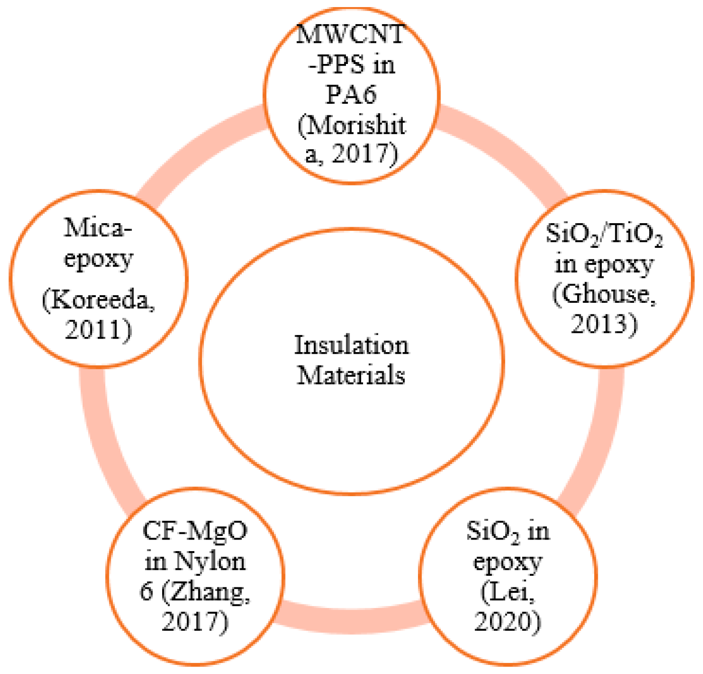
4. Insulation Materials and Performance

Next-generation electric machines are in pursuit of identifying electrically insulating polymer materials. In order to achieve a better cooling performance and thereby increase the power density and torque density, those insulating materials have to have a good “k”, or thermal conductivity. Secondly, to compensate for the stresses developed by the high temperatures caused by the hot spots of the motor, those insulating materials must also have a good “Y”, elastic modulus. In fact, the next-generation electronic devices are also seeking a similar kind of material with a good “k” and “Y”. Extremely high thermal conductivity and elastic modulus are shown by carbon nanotubes (CNTs). For better performance, multiwalled CNT (MWCNT)/polyamide-6 (PA6)/poly(p-phenylene sulfide) (PPS) composites, having great “k”, electrical insulation and “Y”, were designed and fabricated. Nano-sized PPS domains (MWCNT-PPS nano domain-linked structure) were used to cap the MWCNT ends to thwart electrically conductive tracks from developing. MWCNT-PPS nano domain-linked configurations were evenly disseminated in the PA6 matrix, for boosted elastic modulus and heat resistance, thermal conductivity (k) and electrically insulating properties. Composites of this kind are highly capable of electrically insulating materials for the great output of electric motors [49]. Figure 6 shows the materials used for insulation in electric motors.
Nano-fillers are mixed with epoxy resin for using the nanocomposite as a dielectric/insulator in power apparatus. SiO2 and TiO2 are mixed in appropriate proportions with epoxy resin, and divergent electric fields are used in experimentation. Classical tests, such as switching impulse tests, lightning impulse tests, and DC voltage and AC power frequency tests, are carried out on epoxy dielectrics. A non-classical tests, the high-frequency high voltage breakdown test, is carried out to assess the possibility of using the nanocomposite in high-speed switching devices. The nanocomposites are found to have better voltage endurance characteristics and may function as a credible shielding substance for power apparatus [50]. Epoxy resin was doped with SiO2 particles to fabricate the insulation used in high-voltage motors. At different temperatures, AC breakdown strength was measured. Conductivity and surface morphology tests were conducted. It was shown that the doped nano-SiO2 particle in dielectric composite improved electrical breakdown strengths, and this composite is suitable for insulating high-voltage motors [51].
A carbon fiber magnesium oxide (CF–MgO) hybrid was developed, since it is thermally conductive but electrically insulating, as the filler for the polymer mix. When this filler was introduced into Nylon6, the highest thermal conductivity was obtained. The insulation was found to be higher with a 10 wt. % addition of the hybrid fiber [52]. The mica-epoxy-based composite has compatible thermal characteristics and insulation properties. The thermal characterization of mica composite; its components, zinc naphthenate, epoxy resin, anhydride methylhexahydrophtalic and mica tape, are provided. The intrinsic properties of this composite give a great thermal and electrical performance [53].

5. Thermal Mapping and Analysis

Thermal mapping is the scientifically proven technique for creating accurate temperature profiles of the machine. Thermal mapping helps designers to measure the temperature of the motor components under steady-state and intermittent operating conditions for the precise modeling of thermal behavior. Through mapping, it is possible to detect the components that are likely to heat up and deploy the tools to sustain the system under secure operating conditions. Understanding the key paths of heat transfer offers possibilities for motor manufacturers to dramatically increase the power performance of motor efficiency and make design decisions. As the automotive sector begins to migrate toward more electrically dominated propulsion systems, thermal management is crucial for electric motors. The complexities associated with thermal management for electric motors are increasing, aiming to minimize the size of the component, and reduce weight and costs without compromising reliability and efficiency. An optimized thermal architecture will help to significantly increase the rated capacity of the unit, almost without any increase in its production costs. The thermal control of electric motors is a dynamic task, because of the multiple thermal transfer pathways within the motor, i.e., multiple materials and thermal interfaces, from which the heat must travel to be expelled. There are various methods for obtaining the thermal information from the machines, such as the infrared thermography (contactless) method and thermistor (contact) method [54,55,56].

5.1. Infrared Thermography

The identification of infrared radiation emitted by the machine with a temperature above absolute zero is the basis of infrared thermography. This radiation is transformed by thermography into visible light, which results in a thermal image. The surface temperature field of the machine is mapped, which makes it possible to assess the strength of radiation. Thermal vision cameras allow the digital measuring of the temperature distribution of the test machine. This temperature map is graphically represented. Since all temperatures are allocated a different color, the thermal picture of the machine is seen in the viewport. In reality, when the data are stored as a temperature chart, based on the adopted color scale and the relationship to the temperature scale, the same entity can appear different. Thermo-vision is an efficient and non-invasive diagnostic way of obtaining the surface temperature field of the tested objects in the form of photographs using thermographic cameras.

5.2. Thermistor

Thermistor is a conjunction of the words “thermally sensitive resistor”. A thermistor is a specific category of resistor that changes its physical resistance during temperature change. Thermistors are made of semiconductor material of a ceramic form using metal oxide processing, such as nickel, manganese, cobalt, etc. The thermistor is normally pressed into small discs or balls that are sealed up to provide a rapid reaction to temperature changes. It is a passive resistive device, meaning that to achieve a measurable voltage output, we need to transfer a current through it. Thermistors are then wired in series via an appropriate biasing resistor to form a voltage divider circuit, with the resistor chosen to achieve a voltage output at a pre-determined temperature value. Their key advantage over forms of snap-action is their reaction speed to any temperature, their accuracy, and their repeatability adjustments. Major thermistor types have a negative temperature coefficient of resistance, that is, their resistance value decreases with a temperature rise.

5.3. Resistive Temperature Detectors

Precision temperature sensors manufactured from high-purity conducting metals such as titanium, copper, or nickel, wrapped into a coil and whose electrical resistance varies as a function of temperature, analogous to a thermistor, are known as resistive temperature detectors. Resistive temperature detectors have positive temperature coefficients, but their performance is highly linear in contrast to the thermistor, providing very precise temperature readings. However, they have very low thermal sensitivity, which means that a temperature rise only causes a very slight change in performance. Resistive temperature detectors are passive resistive devices that create an output voltage that increases linearly with temperature by passing a constant current through the temperature sensor. As the resistive temperature detector is a resistive device, a current should pass through it for observing voltage. Even then, as the current passes through it, some differences in resistance due to the self-heating of the resistive wires, the I2R law, produces an error in the readings. To prevent this, the resistive temperature detectors are normally wired into a Wheatstone Bridge network with additional wires for lead compensation and/or access to a continuous current source.

5.4. Fiber Optic Temperature Measurements

Even in dangerous environments, fiber optic temperature sensors without external effects (radio signals, magnetic fields, microwaves) can operate rapidly and easily. They can be used conveniently to calculate an engine’s stator winding temperature or the temperature of the bearing. The sensors help to easily sense variations in temperature to record the real conditions and trigger preventive steps [54,55,56]. Table 2 shows the comparison of different measuring techniques against operating parameters.

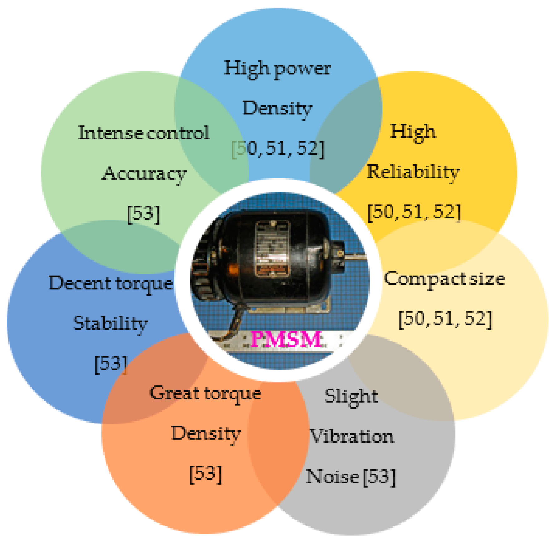
5.5. Permanent Magnet Synchronous Motor

Electric motors with greater power density and a proven record of extended running period are the best resources for meeting the demands. They are the prime movers in the automotive, rail, marine, and aerospace conveyance sectors [57]. The synchronous motor and induction motor are the two types of traction that motors mostly utilize in EVs [58]. In hybrid drives, basic recommendations have been made for the design of a traction motor, such as that of the spatially constricted space and the necessity for a high power density and high torque density. This allows the motor to support greater power inside a smaller volume, resulting in an increase in the generation of heat within the engine and a decrease in the productive cooling space. With a high power density, high performance, high reliability and compact size (Figure 7), the PMSM is a popular option for the growing electric vehicle industry, as well as for vehicle energy and power applications [59,60,61]. PMSMs are also known for their slight vibration noise, great torque density, decent torque stability and intense control accuracy [62].
Currently, the enclosed PMSMs have been swiftly industrialized across the globe. Rotor cooling is a challenging assignment in motor design, as the heat dissipation is unidirectional [63]. On the thermal design side, the PMSM has many limitations, such as its vulnerability to coil insulation failures and magnet demagnetization under extreme thermal environments [59,60]. The normal motor has deprived conditions of heat dissipation that are constrained by the spatial and environmental challenges, and a great rise in operating temperature boosts torque and power densities [64].
An investigation has shown that the stator winding is the most heated unit of the motor, the rotor winding is the next most heated, and the frame is the least heated unit. It is also known that the highest temperature value of both stator and rotor windings is reduced by about 70% of its length from the supply of cooling air [65]. It is important to avoid such harm in order to envisage a precise temperature distribution in various elements of the electric motor. Therefore, it is important to have effective cooling for greater heat dissipation in PMSMs [59]. Despite their high performance, electric motors are thermally restricted by many forms of losses in some operating points. The essential components of temperature overheating decrease efficiency (derating), and suitable cooling must be implemented to decrease the derating. The design of effective electric motor cooling models in traction drives with improved torque and power densities is difficult because the heat release in various parts of the motor differs significantly from the operative conditions [66,67].

5.6. PMSM Thermal Analysis

Electric motor effectiveness is estimated by its electromagnetic configuration and thermal design. A detailed thermal analysis is still in operation, with emphasis on the temperature captured by the sensors kept in the vicinity of the copper windings, to recommend potential methods to lessen the motor working temperatures. Although the electromagnetic losses of the windings depend on temperature, improving overall cooling often means achieving enhanced motor output in terms of torque supplied, the power developed and the efficiency achieved, as that is the real objective. In view of the electrical power densities, an effective thermal simulation of the engine and the combined cooling system is crucial for the efficient thermal control of the engine. In fact, high temperatures are unfavorable in terms of the efficiency and life of many materials, so good cooling systems are necessary. Excessive heat lowers the battery life, weakens the motor magnets’ rare earth, and facilitates the dissipation of the copper windings by Joule heating. It is mainly important to determine the heat sources in a thermal model and also to predict the heat transfer mechanisms across the entire motor. The mechanism of heat transfer could be conductive, convective, or radiative, identified by the type of cooling system. The electromagnetic eddy current loss, hysteresis loss in magnets and laminations, and Joule heating are the primary sources of thermal energy. The objective was to lessen the running temperatures of the motor’s hot spots (to be precise, in the copper windings) through the optimizations of the most critical factors for a safe operation and long lifetime [14].
The problem of overheating is most likely to arise with the deficiency of the radiation flow path, eventually causing operation issues or even loss. Overheating would demagnetize the PM and would reduce the PMSM’s dynamic efficiency. The cooling system can be disabled by an overly high coil temperature. In addition, the lubricating property and resilience of the bearings are reduced by overheating, curtailing the durability of a PMSM. Overheated hot spots in the parts of the electric motor often threaten to deteriorate the capability of the rotors, which are vital. Investigations identified that longitudinal rotor extension due to uncontrolled temperatures resulted in significant safety problems and added expenses in the making of PMSMs [62] (Figure 8).
The most overriding stator/rotor core losses were estimated by 2D FEA for all the components of an electric motor. The analysis of the stator and rotor core losses was investigated for an uninterrupted power situation, Figure 9. Core losses for the elements of the motor increased with the speed of the rotor, as predicted, but the losses of the stator yoke were the least responsive compared to others. The copper losses under continuous power functioning settings were another main loss factor (Figure 10). These losses were calculated at 180 °C, and the performance, output power and torque of the electric motor under continuous speed power were estimated (Figure 11) [68].

6. Cooling Methods

The operating stability and durability of the PMSM are constrained by greater temperatures at the hot spots and the inefficient heat dissipation, as discussed earlier. The proper quantification of electric motor heat generation and sophisticated coupled motor cooling practices are topics of considerable importance [69]. Generally, air-cooling, water-cooling, oil-cooling, water–glycol-cooling and phase change evaporative-cooling are the active cooling strategies for the thermally stable operation of an electric motor. The active cooling system structures, such as a housing with fins, housing with water jacket, oil spray end winding cooling, etc., were integrated into the thermal scheme to envisage the precise temperature. The simple and economical air-cooled motor (ACM) with a fan at the end of the shaft influences the air inside and promotes heat exchange with the environment. The air-cooling system, however, does not completely meet the increasing demand for heat dissipation [14,58,62]. Investigations were done thoroughly on the temperature control approaches, such as an oil spray end winding cooling, liquid cooling by automatic transmission fluid (ATF), forced air-cooling, cooling through phase change materials, and the potting of stator windings with high thermal conductivity materials [57]. Researchers across the globe have analyzed various PMSM structures, such as the rotor and stator stacks, and the rotor and stator cooling ducts, of a PMSM [70].

6.1. Air-Cooling

If the airflow in the end-space could be improved by wafters, in a self-ventilating cooling system, the cooling efficiency of the rotor would be improved. A modern inclined flow deflector was intended to promote the effectiveness of the rotor’s cooling. The difference in air pressure generated across the rotating rotor facilitated the airflow through the vent holes [63]. Researchers across the globe designed and analyzed a popular air-cooling system wherein the fan is fitted externally at the end of the shaft. Normal rotor, winding and PM temperatures were reported to be substantially reduced by air convection and the effect of the airflow path on the motor temperatures [71,72,73,74]. The external fan can, however, raise the electric motor volume and decrease the power density, and this was not acceptable to fully sealed motors [63]. The rotor is the essential factor when it comes to temperature. Temperature sensors detected spikes with the increase in high-frequency current-borne iron losses, and the thermally insulating air gap at greater speeds of the traction drive. The integrated rotor internal air-cooling system was examined, and the potential load was calculated to maximize the thermal use of the electric motor [75].
In the recent past, with just a resin–varnish layer, a fully sealed fan-cooled induction motor was tested with two separate impregnating ingredients, such as epoxy and silicone potting. The products covered and over-molded the total area between the end winding and the metal housing’s inner surface. The novel cooling method was based on a vortex tube that generated a cold air stream to cool the unit. This strategy was evaluated and compared with a typical water-cooling technique. A simulation was conducted to offer insight into the possibilities of the modern technique of cooling. A finite volume CFD was used to evaluate the cooling path in terms of fluid velocity, pressure drops and flow volume in order to make the simulation quite precise and comprehensive in the traction motor [59].

6.2. Water Jacket Cooling

Thermal analysis was explored for an efficient brushless synchronous electric traction motor with PMs and with cooling of the water jacket. The effect of the water mass flow rate on the temperature of different electric motor components has previously been studied. As the mass flow rate of the water increased, it was observed that the temperature of all the system’s heat sources decreased with the rise in the pressure drop across the water jacket (Figure 12) [14].
The cooling system with flux barriers was investigated to improve the cooling effect with proper heat dissipation as a part of the thermal optimization scheme in the PMSM stator. The results were compared to those of the standard cooling jacket by incorporating temperature-measuring sensors. This is presented in Figure 13 and Figure 14. This method of cooling was similar to the traditional design of a water-cooling jacket around the stator. As there was no sheet between the water jacket and the flux barriers, the chilling liquid circulating within the flux barriers substantially increased the chilling field. The flux barriers were isolated from the air-gap by a thin aluminum layer to avoid cooling liquid flowing through the air-gap and creating a short circuit. A more turbulent flow was developed, leading to greater heat dissipation. This cooling technique may be a decent substitute for the traditional jacket in a limited and harsh setting because of the turbulent flow and the increased cooling area [60].
Using different techniques, such as flat wire winding, oil spray end winding cooling and aluminum winding, performance enhancement or cost savings could be accomplished. Based on cooling systems with integrated spiral stator water jackets, a spiral shaft groove, and oil spray components, the performance of the electric motor was predicted. At a 50 °C inlet temperature, with a fluid flow rate of 6.5 L/min and 50–50% water and ethylene glycol mixture, forced convection heat extraction was enacted on both elements. In addition, using an epoxy-type material, the stator end winding region was potted. The entire cooling model was implemented and evaluated for its viability [76].
The external surface of the driving motor stator was cooled by cooling water flowing through the water jacket in an innovative cooling method. In addition, airflow caused by an axial cooling fan mounted at the end of the rotor was used to cool the inner stator and rotor. With an innovative helical flow channel, the water jacket enveloped the stator. The arrangement was such that the cooling air reached the engine through the radial holes across the left end coil, and the other through the tiny stator–rotor gap. Therefore, via the stator and rotor of the motor, an effort was made to boost the water jacket’s cooling system through the forced cooling air, as presented in Figure 15 [77].
Element heat losses and the subsequent temperature distribution of the water jacket-cooled motor were calculated against electromagnetic output, i.e., efficiency. The winding temperature was calculated using compatible sensors at a higher current density. Higher coolant flow rate tests were performed with higher forced convection heat transfer coefficients of up to 5000 W/(m2·K). The results indicated a substantial reduction in the winding temperature [69]. The water-cooled model was examined considering both the radial heat flow in the active portion of the system and the axial heat flow through the end-winding area and the shaft [78].
The PMSM’s water jacket is not only essential for heat dissipation, but also for mechanical safety. In the PM drive motors of EVs, the water jacket is easily damaged while starting, accelerating and climbing in a harsh environment. To ensure steady EV function, the optimal configuration of the PMSM’s water jacket was investigated. In order to determine the optimum volume and scale of the water channel in the water jacket optimization system, a convection heat transfer factor was examined. Secondly, through mechanical optimization design, the mechanical stress on the water jacket was investigated via calculating the optimal thickness of the inner layer of the water jacket. A thorough thermal analysis of the PMSM was done to achieve the best water-cooling jacket [79].
Numerical results for thermal simulations were obtained using CFD software ANSYS Fluent for a BMW i3 PM synchronous motor. Outputs such as torque, winding and stator losses, and peak winding temperatures were analyzed for direct stator cooling (rectangular and circular channel) and a direct winding heat exchanger with the conventional jacket-cooling technique. The direct winding heat exchanger was proven to be more effective in lowering the winding temperature, because it offers double the surface area and much less thermal resistance compared to the other cooling methods at the same heat transfer coefficient (Figure 16) [80].
Researchers inserted water cold plates (WCP) radially into the core laminations such that hot spots in laminations and windings were close to the coolant. The heat transfer path in the WCP is in an axial direction with better thermal conductivity, and it is in the radial direction in WJ with lower thermal conductivity. The performance of the PMSM with WCP and with WJ was analyzed using CFD, and the results were compared. The winding and PM temperatures with the WCP were less than those with the WJ. In addition, at higher torques, the PMSM with WCP displayed a better thermal advantage compared to WJ (Figure 17). It was observed that the winding temperature could be reduced by over 20 °C with WCP compared to WJ at the rated condition [81].

6.3. Liquid/Oil-Based Cooling

In motors, liquid-cooling is designed to transfer the heat produced by stators and windings through the water jackets to the cooling fluid. Using encapsulating varnish or Epoxylite, the heat dissipation of the end winding could be dissipated through the casing [16,17,82]. A 30,000 rpm speed automotive traction motor oil-based shaft cooling system was investigated. Thermal analysis was done analytically and experimentally. The results in Figure 18 indicate that the shaft temperature decreased despite the rise in the speed of the shaft for different iron losses with oil-based cooling. The results in Figure 19 also show that the shaft temperature decreased as the oil flow rates increased for different iron losses with oil-based cooling [83].
The oil-cooling configuration for the end winding and stator core was investigated as the inner rotor motor was considered to be the research focus. The results revealed that the heat inside the motor was carried away by the lubricating fluid via heat conduction and convection. The analysis comparing this with the water-cooled motor revealed that the rate of temperature increase of the oil-cooled motor was slower than that of the water-cooled motor. It was also found that the temperature difference across the motor front and back decreased by 18 °C in half an hour (Figure 20). In general, because of complex pipeline connections, water jacket-cooling was challenging. It was also found that with the water-cooled circuit, the sealing structure had insulation concerns and issues. The oil-cooled system was tested for its cooling effect on the core of the stator. Investigations found that not only was the cooling effect viable, but it also worked for extended periods under rated conditions. For the end winding or stator core cooling, the cooling structure and cooling methods were configured as the motor losses were primarily concentrated there. The cooling structure was designed in such a way that the cooling oil and the heat source were kept closer for a better cooling effect. Therefore, coolant oil was transmitted through the holes of the end oil cover and the stator core. The oil-immersed end winding and the axial oil passage cooling of the yoke of the stator and stator core were investigated for their effectiveness as regards cooling, and so too were the enhanced hub motor power density and torque density [64].
To increase the performance of the EV motor for greater power density, the optimization of the liquid cooling system is vital. Following the design assessment of parts such as lubricating oil and the motive seal of electric cars, revolutionary cooling topologies of electrical machines were investigated. Different winding insulation schemes were studied, such as impregnation using standard varnish only, as well as potting with a standard epoxy and a highly thermally conductive potting silicon gelatin (PSG) material. A stator winding fixed cooler structure was also investigated for its effectiveness on cooling and service life. There were jacket openings on the fixed coolers for the stator winding. The jacket was supplied with oil through gravity, whereas the stator was supplied through pressure-based injection. Stator winding rotary coolers would enhance the end winding heat transfer. Under the operation of centrifugal force, the liquid would enter the stator winding rotary cooler. For the customized design of the electric motor cooling system, the stator winding rotary cooler and the air-gap cooling cavity were found to be convenient. This is one of the innovative designs of the cooling topologies for EV electric motors that could uphold efficacy at high speeds and substantial loads [84].

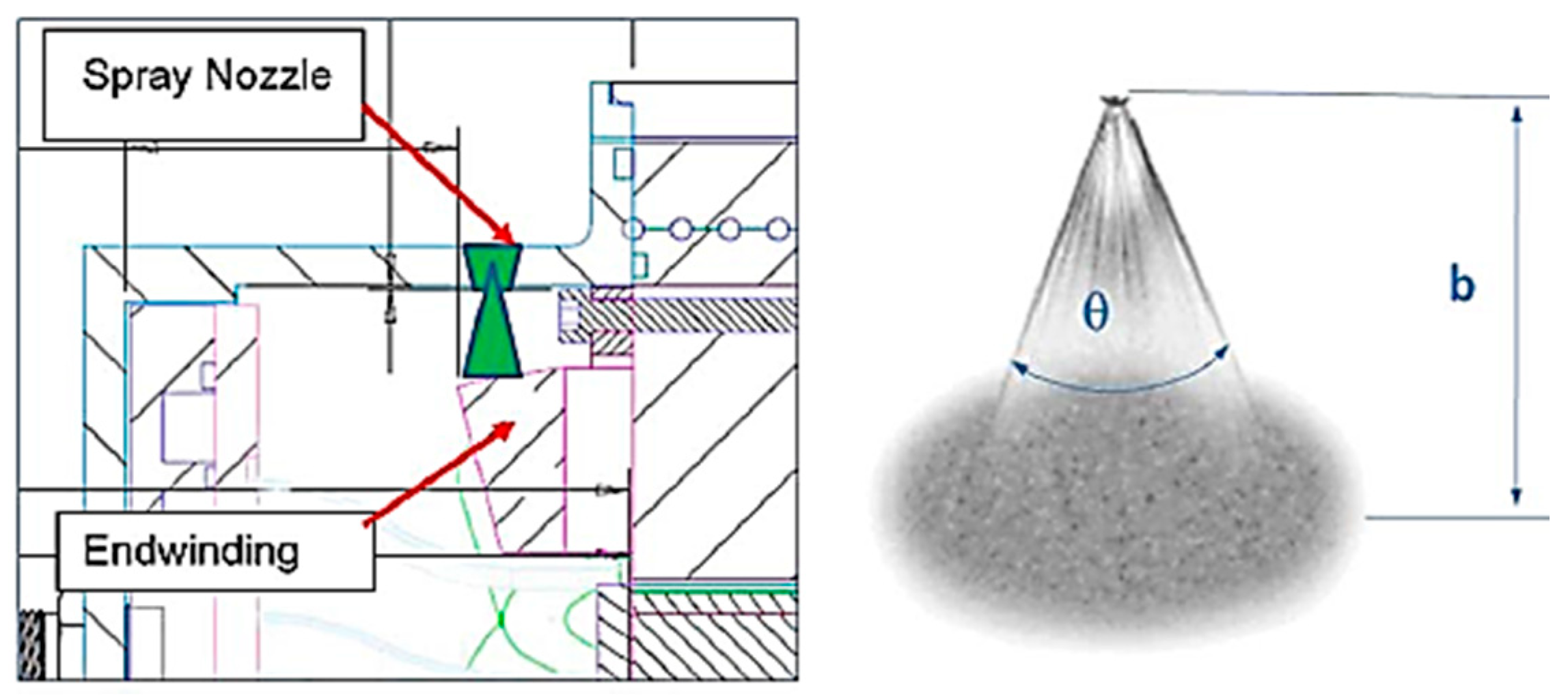
6.4. Oil Spray Cooling

The best way to lessen the temperatures of an electric motor is to keep the heat sinks in the vicinity of the heat sources. In modern PMSMs, three types of parallel strategies were implemented and tested (Figure 21): the injection of oil into the revolving shaft through holes; oil injection into the housing through nozzles; external cooling jacket. Direct spray cooling was undertaken with rotor shaft nozzles equipped for the cooling of end windings. The cooling oil (dielectric fluid) was injected into the electric motor’s (mostly air-filled) interior with a jet at variable volume flow speeds through the revolving shaft’s holes [66].
The end winding is in general considered to be one of the prime heat sources in the electric motor. Spray nozzles were used to spray oil to cool the stator end windings (Figure 22). Investigations were done and various cooling schemes were analyzed for their effectiveness in bringing down the temperature of the heat sources. End winding spray cooling with water jacket cooling is considered to be the best, as the temperature rise permitted through this scheme is slower compared to the other cooling schemes as the rotor speeds increase (Figure 23). In addition, in comparison to the other cooling schemes, such as microchannels and cooling tubes, end winding oil spray cooling is proven to be the best (see Figure 24) [68].
The uninterrupted performance of the electric motor was investigated, and the results indicated a significant improvement and gain was achieved with the oil spray-cooling (SC) in contrast to stator spiral water jacket (WJ)-cooling (Figure 24). The stator spiral WJ system has a strong but minimal heat removal capability, hence it was suggested to be utilized in combination with SC. The results also indicate that the maximum value of continuous torque was greater than before, increasing from 185 Nm to 315 Nm when both cooling systems were involved. In addition, the maximum value of continuous power was greater than before, increasing from 68 kW to 98 kW with the combination of both the cooling systems (Figure 25). Oil spray-cooling systems were found to be economical to establish, and were recommended for utilization as a secondary mode. This strategy was suggested to remove the heat and to enhance the performance of a traction motor considerably. The oil spray-cooling showed great potential in dissipating the heat as a single unit as well [76].

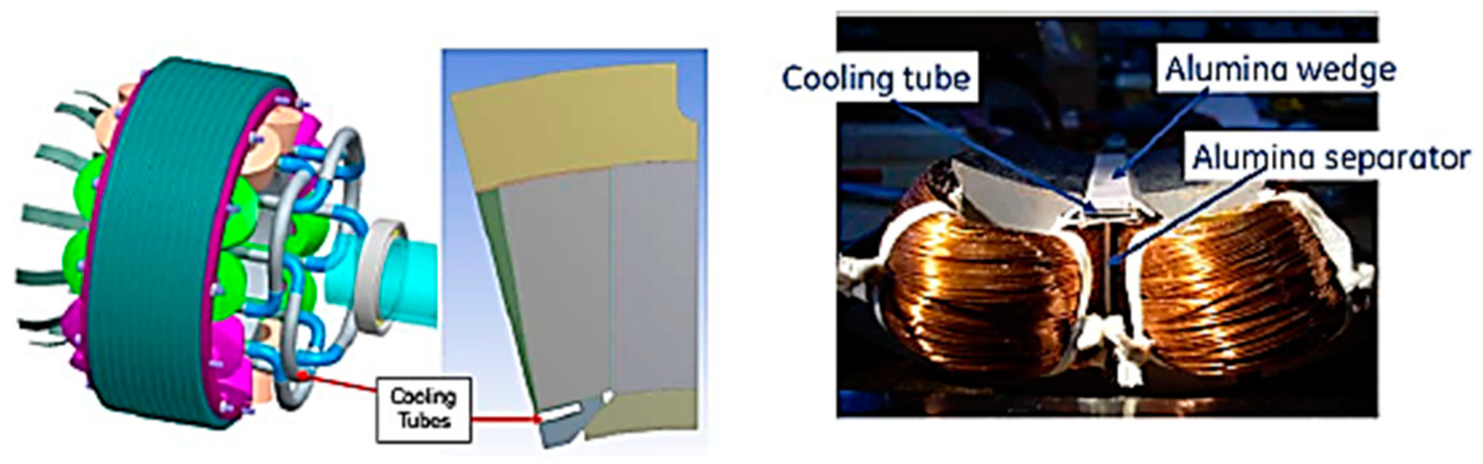
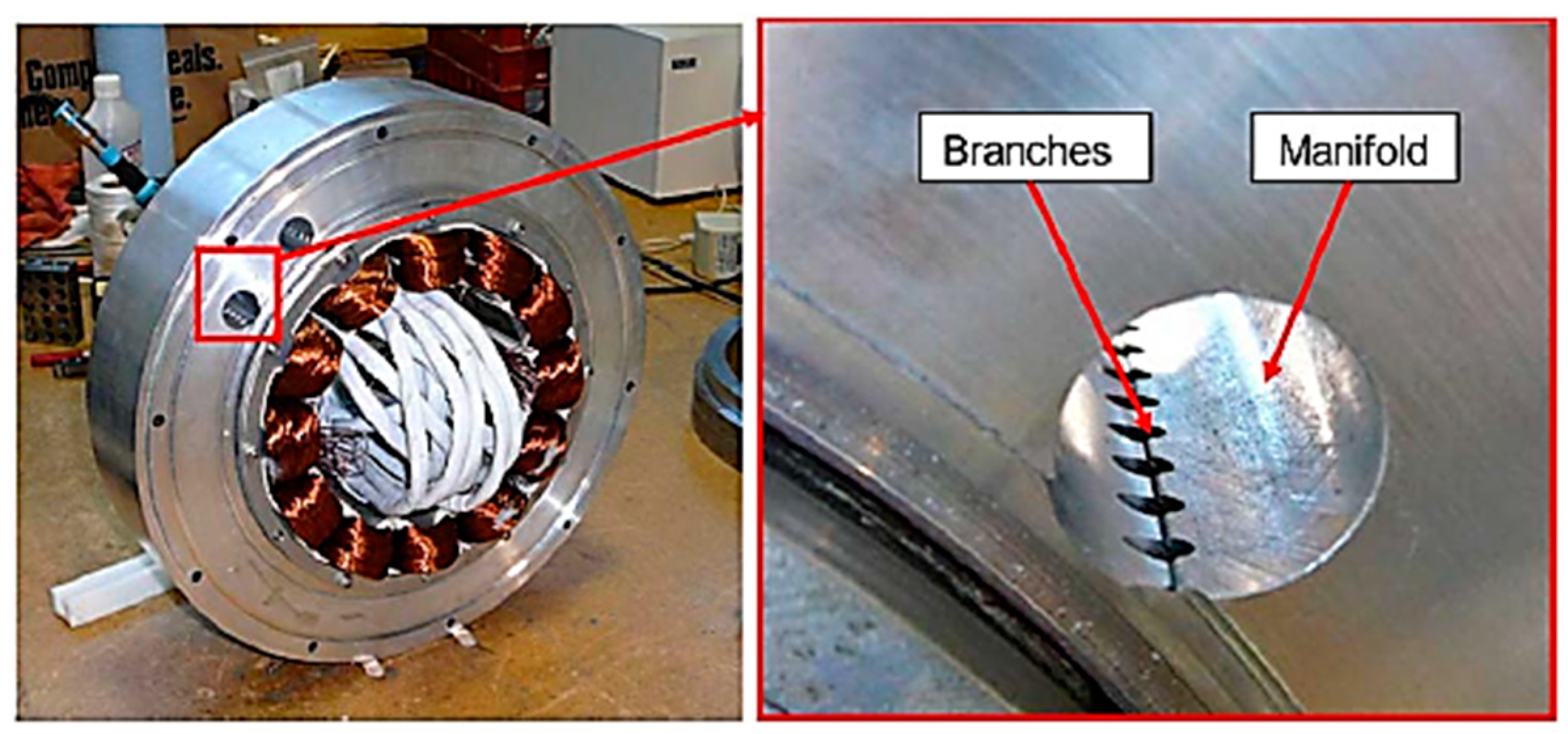
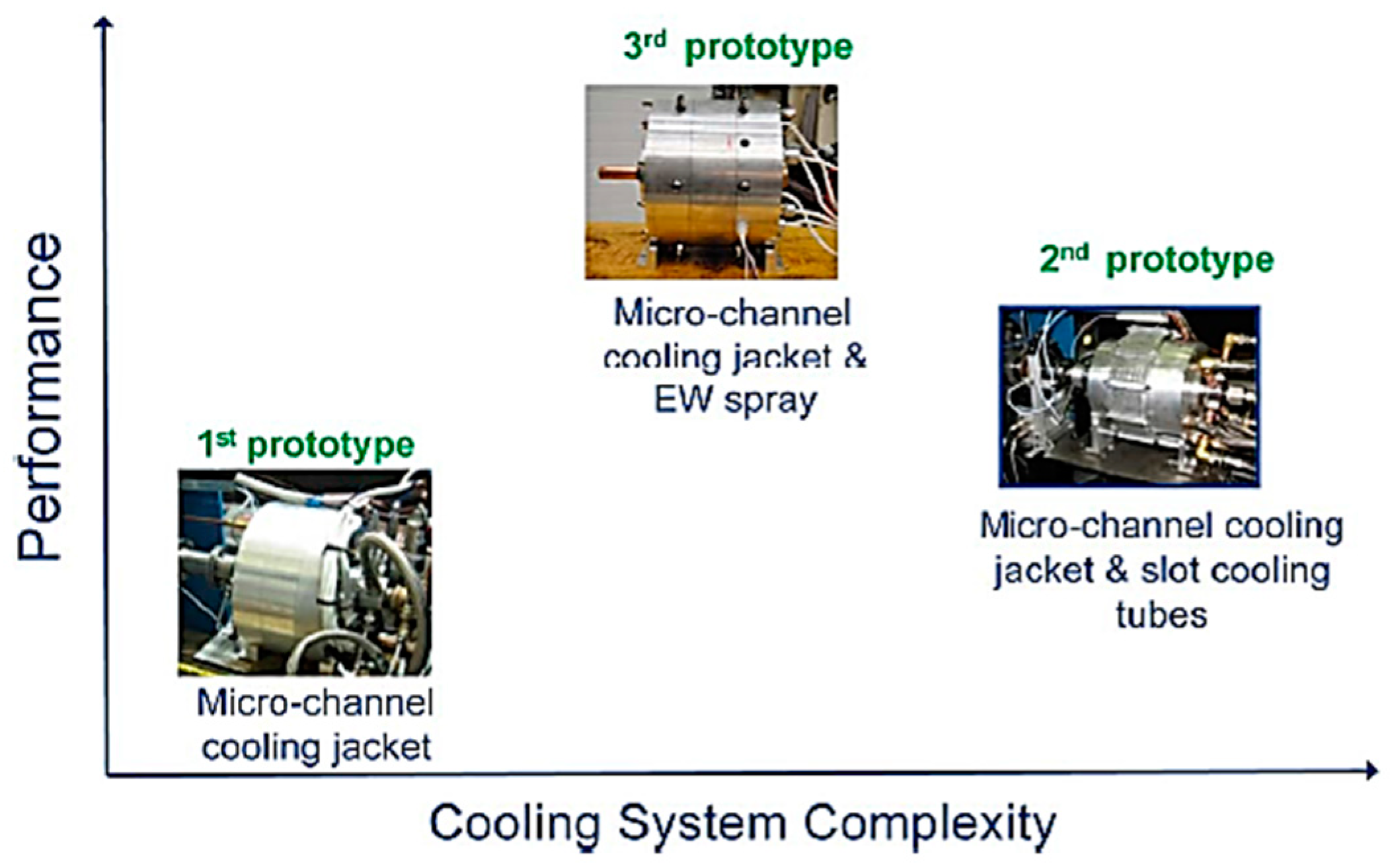
6.5. Cooling Tubes and Microchannels

Researchers across the globe are investigating various cooling schemes in an attempt to bring down the temperatures at the hot spots of PMSMs. In order to obtain a better cooling effect, one of the cooling schemes investigated was cooling via cooling tubes inside the stator slots, along with a cooling jacket (Figure 26). This cooling scheme could fulfil the objectives, but was found to be complex. Another cooling scheme investigated involved having a cooling jacket, with circumferential cooling passages, shrunk-fit at the stator outer diameter (Figure 27). These cooling schemes were compared to microchannels with end winding oil spray-cooling (Figure 28) [68].
A compact microchannel thermal management cooling jacket was investigated for cooling the stator core. In this cooling scheme, hollow conductors were employed in direct winding cooling. The cooling jacket’s ring-shaped construction was such that the inner surface fit closely to the core of the stator, and the outer surface fit closely to the control electronics. Inside the cooling jacket, a complicated fluid path was built to bring down the values of pressure drop and pumping strength, and to raise its thermal efficiency. As the stator winding was known to be a hot spot, hollow conductors enabled the coolant to directly access the end windings, to overcome the thermal resistance between the stator and the winding. The same coolant and cooling loop could be shared by the jacket and the winding cooling mechanism, minimizing the complexity of the pumping, radiator and reservoir structures [85].

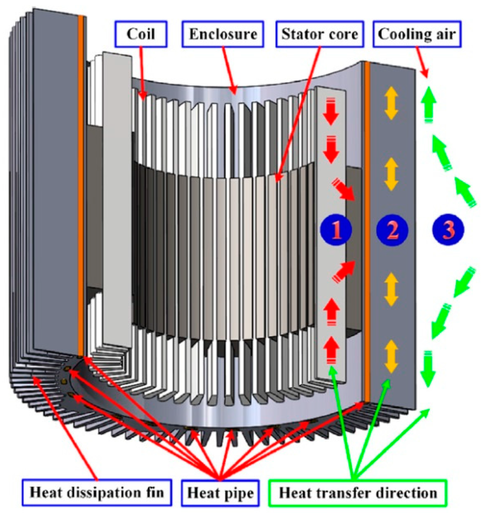
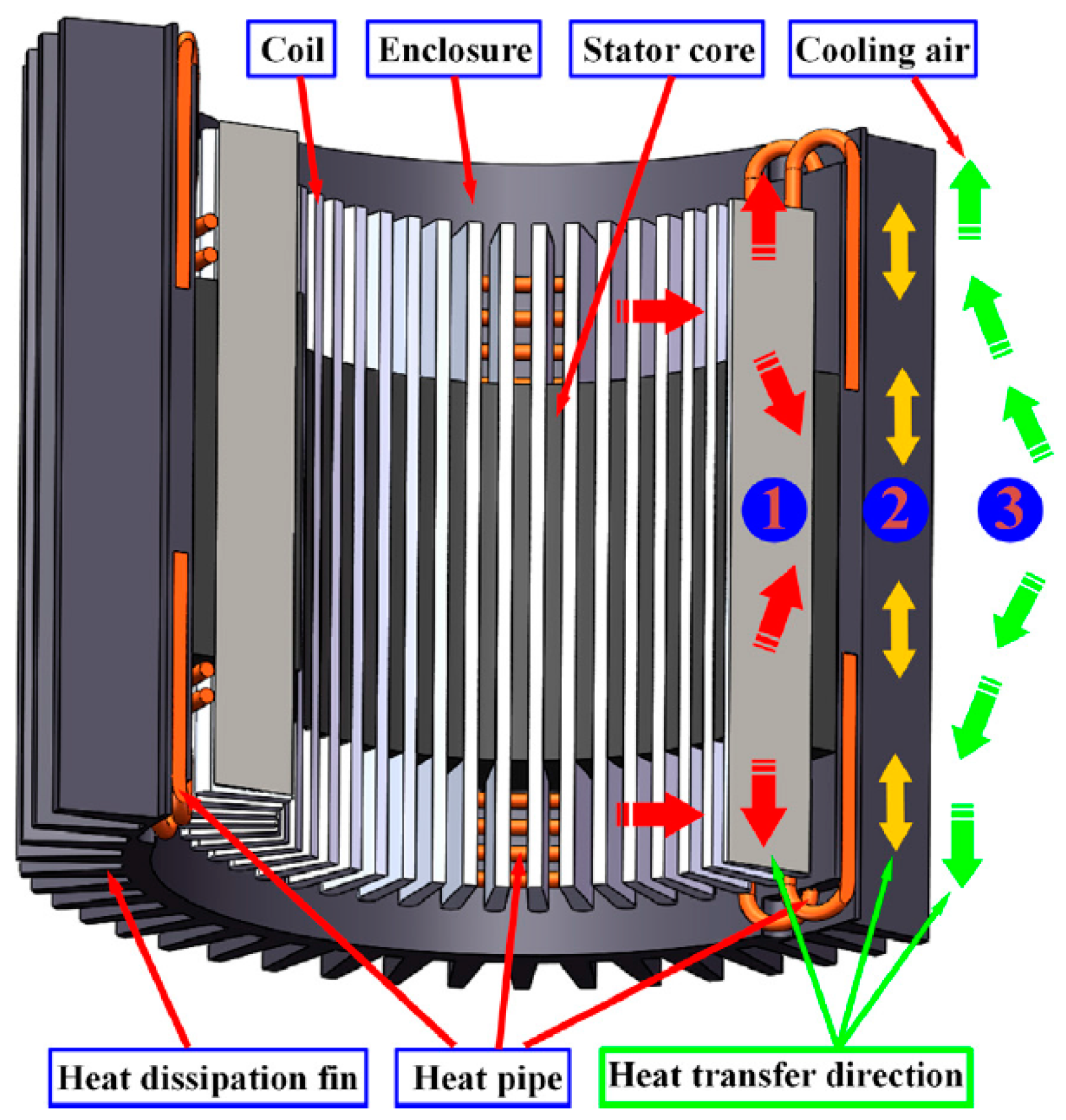
6.6. Heat Pipe-Cooling

An innovative phase-change heat pipe-cooling scheme for PMSMs has been investigated. A heat pipe-based straight-embedded module (SEME) (Figure 29), a three-dimensional rounding module (RM) (Figure 30), and thermal management modules for ACMs were analyzed. The experimental results indicate that the operative time required to control the temperature of a PMSM could be extended by 28.6% (under high speed) and 21.4% (under high torque) with this phase-change heat pipe-cooling scheme. In addition, the power density of the PMSM was enhanced while reducing the peak temperature by 22.3% (under rated conditions) (Figure 31) [62].

6.7. Potting Silicon Gelatin (PSG) Cooling

Investigations into air-cooling for electric motors in EVs are complicated in certain areas with poor heat transfer abilities. Secondly, concerning electric motor topology, the direct liquid-cooling of traction motors could be difficult to introduce. The decay of oil at hot spots inside the windings is a major problem in direct liquid cooling, which would impact the heat exchange. Forced air-cooling and direct liquid-cooling approaches, therefore, face both spatial and inherent issues. Investigators identified and tested liquid-cooled motors with thermally conductive potting materials. The electric motor end winding was permeated with a conventional epoxy-based substance and potted with thermally conductive epoxy. A single material was impregnated with common resins in the global potting motor. The results indicated that the heat transfer was improved considerably by moving from the copper winding to the cooling ducts’ fitted housing. Investigations established that enhancing the heat transfer resulted in a higher power density and enhanced motor life with lower winding temperatures. The end winding potting was designed and applied to a real size PM water-cooled traction motor by researchers. On a potted motor and an unpotted motor, the test findings were examined under steady-state, running and duty cycle conditions. The results indicated a substantial enhancement in the thermal efficiency of the traction motor under both steady-state and duty cycle applications. Furthermore, in the stator and rotor, potting lessened the temperature substantially. The optimal direct heat transfer from the hot spot (end winding) to the coolant-fitted frame by conduction was facilitated by the stator potting (Figure 32) [16,21,57].
The temperature analysis findings for the prototypes revealed that the winding temperature was lessened considerably by both potting methods. The same thermal effect as with the end winding potting could be achieved with global potting using resins with considerably poorer thermal conductivity. The positions of temperature sensors are denoted by line patterns in Figure 33.

7. Future Scope

The design of an effective electric traction motor is very much the need of the hour, as the demand for EV is gaining momentum all over the globe. Improved and more efficient motor development is possible with a well-designed thermal model and with an effective thermal simulation. The thermal model should also consist of cooling schemes in the pursuit of enhanced output power, torque density and efficiency. An improvised thermal model of an electric traction motor is used to predict and investigate heat release in various parts of the motor, as they differ significantly with the operative conditions of the motor (see Figure 34). Highly thermally conductive and electrically insulating polymer materials, with good elastic modulus, are hugely sought after for the next generation of electric machines and electronic devices.
Future research into this topic may consist of advanced thermo-mechanical and thermo-electrical analyses of the PMSM motors in order to verify the optimal solutions of the cooling schemes and to minimize the hot spots. In addition, future investigations would extend proposed and reviewed thermal mapping approaches for the high-speed motor spindles and high-power motors, with included uncertainties. Another topic for future research is to compare the different motor topologies and their performances, which depend on the most suitable cooling system.

8. Summary and Conclusions

In this paper, a review of the thermal mapping and cooling solutions has been undertaken for the permanent magnet synchronous machines (PMSMs). The major results of the motors’ thermal analysis, structure design and optimization are presented based on the review of the recent most important research works and reports. Particularly, this literature review discussed thermal and structural design methodologies and cooling schemes for the PMSM traction machines, with an emphasis on the efficiency improvements over output powers and rotor speeds. The following outcomes are highlighted:
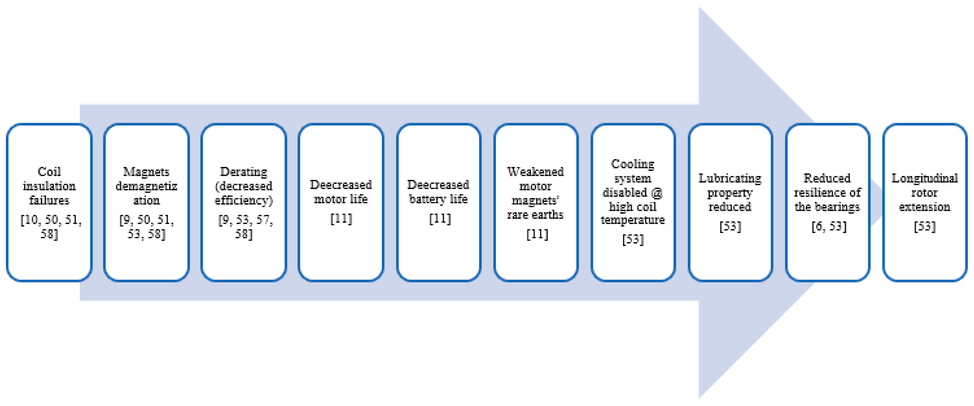
  • Traction motors for multi-quadrant operation and synchronization need a high controllability which, due to their high power, is a challenging task. In this context, the thermal augmentation of the motor core, insulation and permanent magnets are the main factors that influence the machine’s performance and life span;
  • Thermal mapping is an essential tool providing thermal motor optimization in order to meet the energy efficiency requirements of modern motors, wherein the PMSMs are mainly developed with novel topologies, namely stator-core solutions, multiphase, and reconfigurable windings;
  • Nowadays, there are noticeable trends towards higher maximum speeds and motor power density, which cause increased heat losses. These losses cause a number of undesired thermal, thermo-mechanical, thermos-electrical, and tribological effects/uncertainties;
  • The high-power motor needs an effective cooling system wherein air-cooling is combined with the more effective liquid-cooling. In order to achieve a high motor performance, the effective cooling system must be managed with the smart thermal control system using multiple temperature sensor feedbacks;
  • Many factors, such as motor topology, geometry, structural design, materials, insulation, etc., have a major influence on motor efficiency and electromagnetic/electrical performance;
  • Effective numeric simulation tools enable the calculation, modeling, design and simulation of the motor operations in different operating environments. This practice speeds up motor optimization, whereby many motor numeric models can be tested very fast and easily;
  • The major trend in motor topologies is toward the adoption of permanent magnet synchronous machines with high power density and cost reductions;
  • Active cooling approaches have become established in PMSM motors due to their fundamentally higher cooling potential than passive cooling solutions;
  • Fluid-based cooling systems are mainly used for cooling both the stator and the rotor, and are more effective in comparison with air-cooling methods. In particular, the indirect cooling of these components by means of cooling channels in the shaft is widely applied;
  • Air-based cooling is only applied if the occurring heat losses are low. The main advantage of air-based cooling systems is the considerably lower requirement for space of the peripheral equipment. However, as the air warms up, the cooling effect is small, and in addition, this approach leads to increased acoustic pollution due to turbulent airflow;
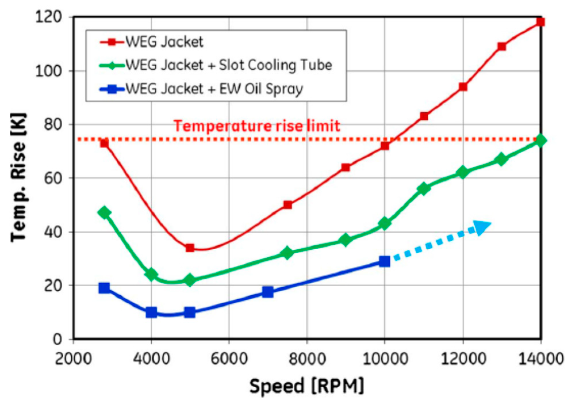
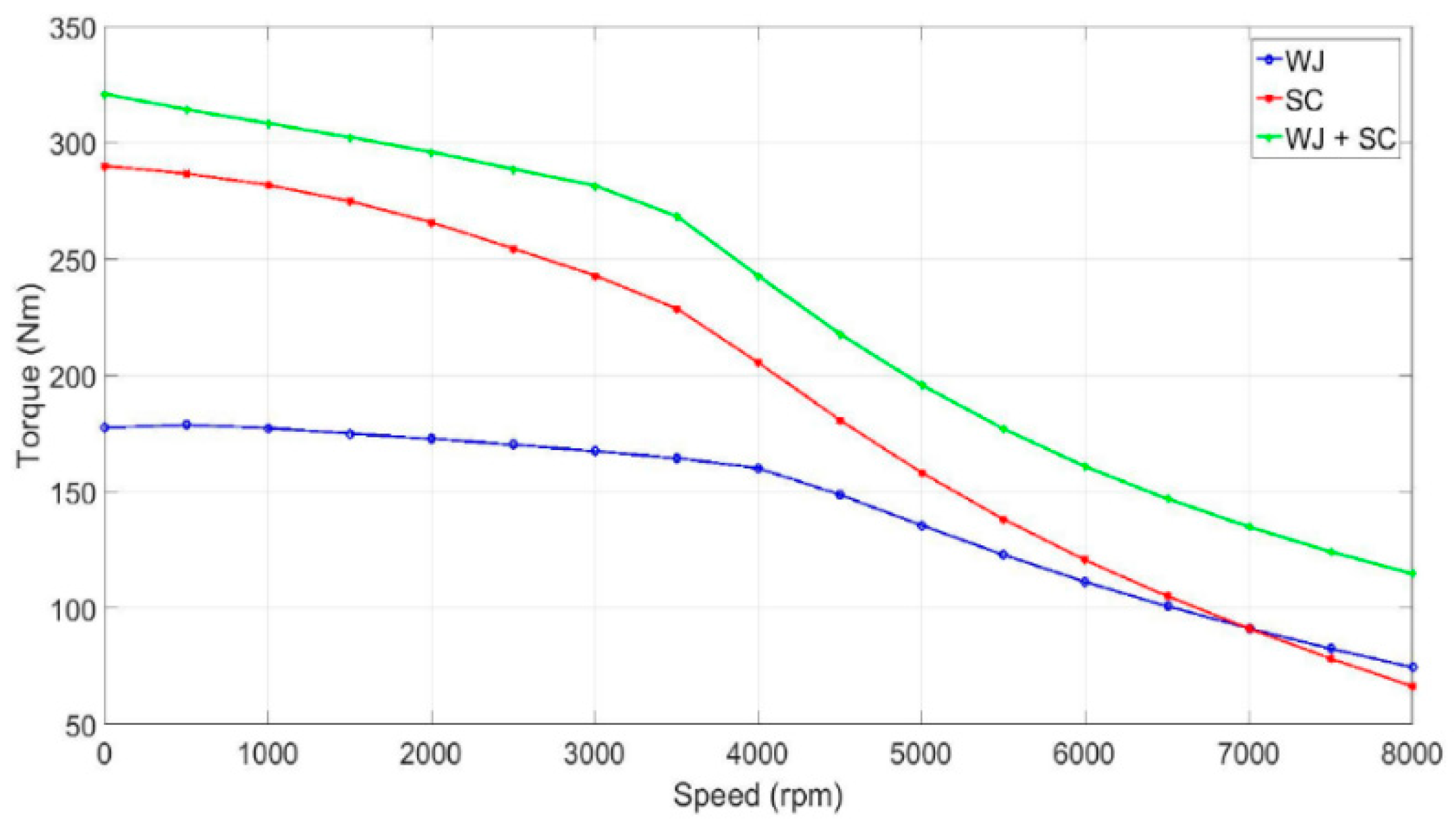
  • Liquid cooling around the stator and through the rotor enables direct operation with a high performance for high-power motors. Using axial channels between the stator windings, the winding temperatures can be reduced up to 60–80%;
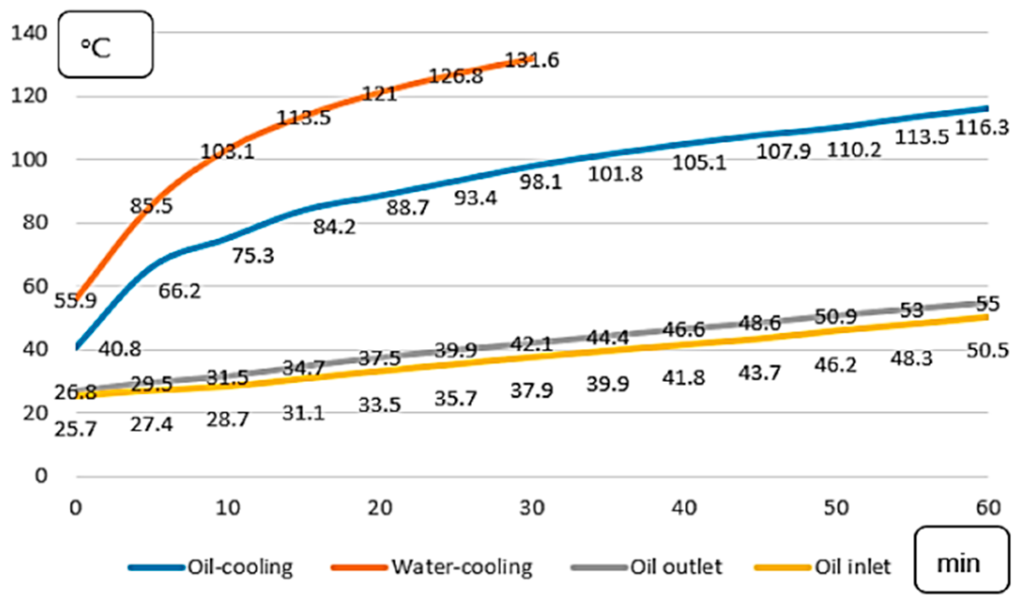
  • The rate of temperature increase of the oil-cooled motor is slower than that of the cooled water-cooled motor. However, these methods have a lower potential in dissipating the heat in comparison with the oil spray-cooling solution;
  • The cooling solutions using cooling tubes and microchannels enable us to bring down the temperatures at the hot spots and to increase motor thermal efficiency;
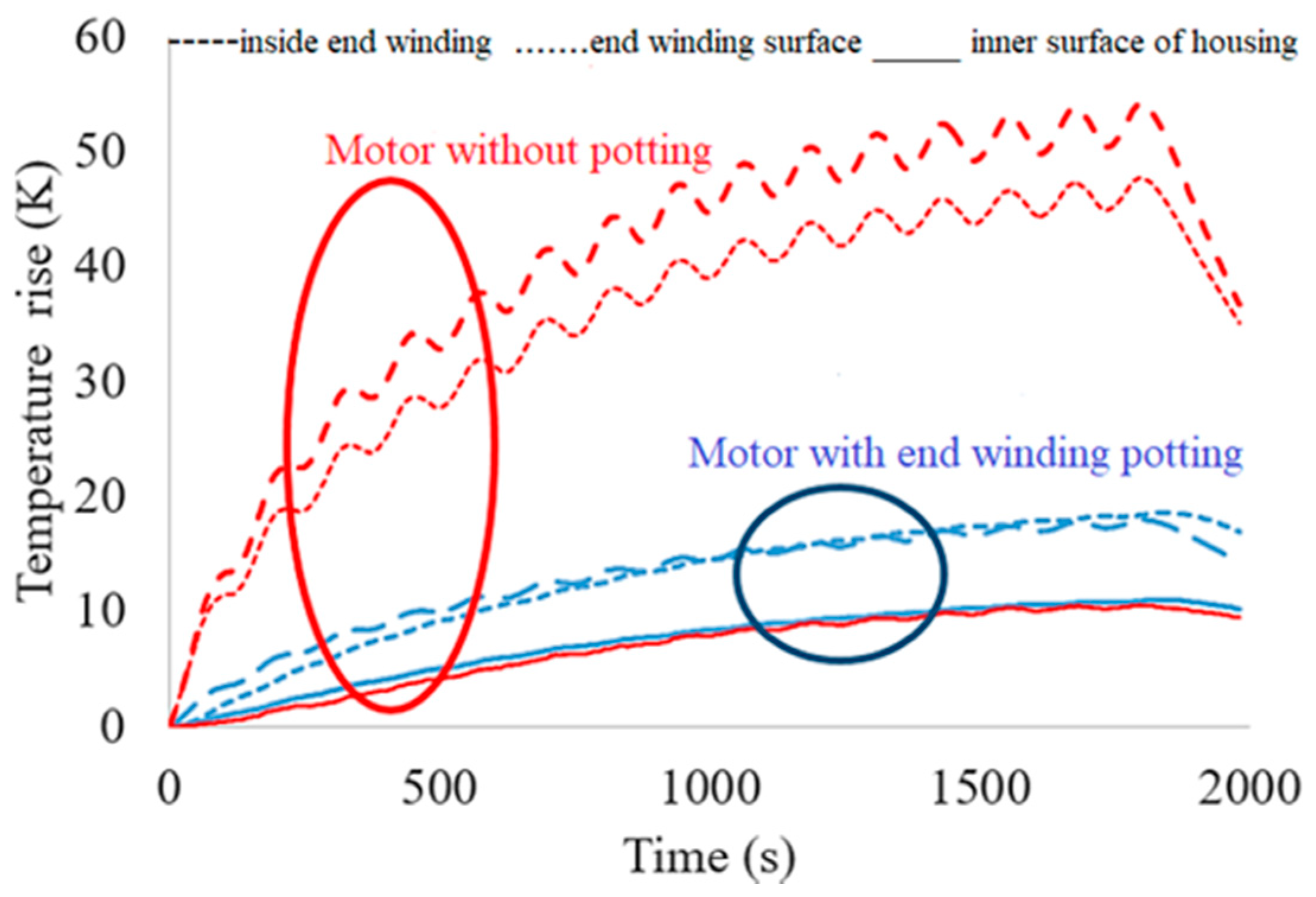
  • In order to increase the heat transfer intensity from the copper winding to the cooling medium, the electric motor’s end winding is potted with thermally conductive epoxy, wherein potting silicon gelatin (PSG) cooling is the most promising solution;
  • The fast development of advanced and new insulation materials based on carbon fibers (CF–MgO), Nylon6, and mica-epoxy, enable us to achieve better and better motor temperature robustness and efficiency values. These new materials are able to offer improved prospects for the design of great performance and/or low-cost motors with innovative manufacturing approaches;
  • Thermal mapping is an essential tool providing thermal motor optimization in order to meet the energy efficiency requirements of modern motors, whereby the PMSMs are mainly developed with novel topologies, namely stator-core solutions, multiphase, and reconfigurable winding;
  • Design optimization achieves both high manufacturing quality and low manufacturing costs, whereby assembling errors can be cleared out, and the low-cost manufacturing technology employed can be used to achieve robust design optimization, incorporating manufacturing tolerances and motor production costs.

Author Contributions

Conceptualization, E.G., R.S.R. and D.G.S.; methodology, E.G.; validation, A.M. and A.I.; formal analysis, E.G. and R.S.R.; investigation, E.G., A.M. and A.I.; writing—original draft preparation, E.G., R.S.R. and D.G.S.; writing—review and editing, A.M. and A.I.; supervision, E.G. All authors have read and agreed to the published version of the manuscript.

Funding

This research received no external funding.

Acknowledgments

Authors are thankful to the managements of Vellore Institute of Technology, India and Faculty of Electrical Engineering, Bialystok University of Technology, Poland, for their continued support. This research is supported by Bialystok University of Technology projects (WZ/WE-IA/4/2020 and WZ/WE-IA/2/2020) and financed from a subsidy provided by the Ministry of Science and Higher Education.

Conflicts of Interest

The authors declare no conflict of interest.

References

  1. Kuntanapreeda, S. Traction control of electric vehicles using sliding-mode controller with tractive force observer. Int. J. Veh. Technol. 2014, 2014, 829097. [Google Scholar] [CrossRef] [Green Version]
  2. Chan, C.C.; Cheng, M. Vehicle Traction Motors. In Encyclopedia of Sustainability Science and Technology; Meyers, R.A., Ed.; Springer: New York, NY, USA, 2012; pp. 11522–11552. [Google Scholar]
  3. Huynh, T.A.; Hsieh, M.F. Performance analysis of permanent magnet motors for electric vehicles (EV) traction considering driving cycles. Energies 2018, 11, 1385. [Google Scholar] [CrossRef] [Green Version]
  4. Singh, K.V.; Bansal, H.O.; Singh, D. A comprehensive review on hybrid electric vehicles: Architectures and components. J. Mod. Transp. 2019, 27, 77–107. [Google Scholar] [CrossRef] [Green Version]
  5. Rahman, M.A.; Chiba, A.; Fukao, T. Super high speed electrical machines—Summary. In Proceedings of the 2004 IEEE Power Engineering Society General Meeting, Denver, CO, USA, 6–10 June 2004. [Google Scholar] [CrossRef]
  6. Tenconi, A.; Vaschetto, S.; Vigliani, A. Electrical machines for high-speed applications: Design considerations and tradeoffs. IEEE Trans. Ind. Electron. 2014, 61, 3022–3029. [Google Scholar] [CrossRef]
  7. Henke, M.; Narjes, G.; Hoffmann, J.; Wohlers, C.; Urbanek, S.; Heister, C.; Steinbrink, J.; Canders, W.-R.; Ponick, B. Challenges and opportunities of very light high-performance electric drives for aviation. Energies 2018, 11, 344. [Google Scholar] [CrossRef] [Green Version]
  8. Cupertino, F.; Leuzzi, R.; Monopoli, V.G.; Cascella, G.L. Design Procedure for High-Speed PM Motors Aided by Optimization Algorithms. Machines 2018, 6, 5. [Google Scholar] [CrossRef] [Green Version]
  9. Rens, J.; Vandenbossche, L.; Dorez, O. Iron Loss Modelling of Electrical Traction Motors for Improved Prediction of Higher Harmonic Losses. World Electr. Veh. J. 2020, 11, 24. [Google Scholar] [CrossRef] [Green Version]
  10. Barré, O.; Napame, B. The Insulation for Machines Having a High Lifespan Expectancy, Design, Tests and Acceptance Criteria Issues. Machines 2017, 5, 7. [Google Scholar] [CrossRef]
  11. Guo, H.; Ding, Q.; Song, Y.; Tang, H.; Wang, L.; Zhao, J. Predicting Temperature of Permanent Magnet Synchronous Motor Based on Deep Neural Network. Energies 2020, 13, 4782. [Google Scholar] [CrossRef]
  12. Frajnkovic, M.; Omerovic, S.; Rozic, U.; Kern, J.; Connes, R.; Rener, K.; Biček, M. Structural Integrity of In-Wheel Motors; SAE Technical Paper; SAE: Warrendale, PA, USA, 2018. [Google Scholar] [CrossRef]
  13. Sarigiannidis, A.; Beniakar, M.; Kakosimos, P.; Kladas, A. Performance evaluation and thermal analysis of interior permanent magnet traction motor over a wide load range. In Proceedings of the 2016 XXII International Conference on Electrical Machines (ICEM), Lausanne, Switzerland, 4–7 September 2016. [Google Scholar] [CrossRef]
  14. Cavazzuti, M.; Gaspari, G.; Pasquale, S.; Stalio, E. Thermal management of a Formula E electric motor: Analysis and optimization. Appl. Therm. Eng. 2019, 157, 113733. [Google Scholar] [CrossRef]
  15. Huang, J.; Shoai Naini, S.; Miller, R.; Rizzo, D.; Sebeck, K.; Shurin, S.; Wagner, J. A Hybrid Electric Vehicle Motor Cooling System- Design, Model, and Control. IEEE Trans. Veh. Technol. 2019, 68, 4467–4478. [Google Scholar] [CrossRef]
  16. Gai, Y.; Kimiabeigi, M.; Chuan Chong, Y.; Widmer, J.D.; Deng, X.; Popescu, M.; Goss, J.; Staton, D.A.; Steven, A. Cooling of automotive traction motors: Schemes, examples, and computation methods. IEEE Trans. Ind. Electron. 2019, 66, 1681–1692. [Google Scholar] [CrossRef] [Green Version]
  17. Farsane, K.; Desevaux, P.; Panday, P.K. Experimental study of the cooling of a closed type electric motor. Appl. Therm. Eng. 2000, 20, 1321–1334. [Google Scholar] [CrossRef]
  18. Tao, X.; Zhou, K.; Ivanco, A.; Wagner, J.R.; Hofmann, H.; Filipi, Z. A Hybrid Electric Vehicle Thermal Management System Nonlinear Controller Design; SAE Technical Paper; SAE: Warrendale, PA, USA, 2015. [Google Scholar] [CrossRef]
  19. Moreno, J.; Ortúzar, M.E.; Dixon, J.W. Energy-management system for a hybrid electric vehicle, using ultracapacitors and neural networks. IEEE Trans. Ind. Electron. 2006, 53, 614–623. [Google Scholar] [CrossRef]
  20. Zhu, C.; Lu, F.; Zhang, H.; Sun, J.; Mi, C.C. A Real-Time Battery Thermal Management Strategy for Connected and Automated Hybrid Electric Vehicles (CAHEVs) Based on Iterative Dynamic Programming. IEEE Trans. Veh. Technol. 2018, 67, 8077–8084. [Google Scholar] [CrossRef]
  21. Oguma, H.; Tsukimoto, K.; Goya, S.; Okajima, Y.; Ishizaka, K.; Ito, E. Development of Advanced Materials and Manufacturing Technologies for High-efficiency Gas Turbines. Mitsubishi Heavy Ind. Tech. Rev. 2015, 52, 5–14. [Google Scholar]
  22. Bernagozzi, M.; Charmer, S.; Georgoulas, A.; Malavasi, I.; Michè, N.; Marengo, M. Lumped parameter network simulation of a Loop Heat Pipe for energy management systems in full electric vehicles. Appl. Therm. Eng. 2018, 141, 617–629. [Google Scholar] [CrossRef]
  23. Shoai Naini, S.; Huang, J.; Miller, R.; Wagner, J.; Rizzo, D.; Shurin, S.; Sebeck, K. A Thermal Bus for Vehicle Cooling Applications—Design and Analysis. SAE Int. J. Commer. Veh. 2017, 10, 122–131. [Google Scholar] [CrossRef]
  24. Aprianingsih, N.; Winarta, A.; Ariantara, B.; Putra, N. Thermal performance of Pulsating Heat Pipe on Electric Motor as Cooling Application. E3S Web Conf. 2018, 67, 03035. [Google Scholar] [CrossRef] [Green Version]
  25. Jouhara, H.; Chauhan, A.; Nannou, T.; Almahmoud, S.; Delpech, B.; Wrobel, L.C. Heat pipe based systems—Advances and applications. Energy 2017, 128, 729–754. [Google Scholar] [CrossRef]
  26. Lei, G.; Zhu, J.; Guo, Y.; Liu, C.; Ma, B. A Review of Design Optimization Methods for Electrical Machines. Energies 2017, 10, 1962. [Google Scholar] [CrossRef] [Green Version]
  27. Shao, L.; Hartavi Karci, A.E.; Tavernini, D.; Sorniotti, A.; Cheng, M. Design Approaches and Control Strategies for Energy-Efficient Electric Machines for Electric Vehicles—A Review. IEEE Access 2020, 8, 116900–116913. [Google Scholar] [CrossRef]
  28. Qu, B.; Yang, Q.; Li, Y.; Sotelo, M.A.; Ma, S.; Li, Z. A Novel Surface Inset Permanent Magnet Synchronous Motor for Electric Vehicles. Symmetry 2020, 12, 179. [Google Scholar] [CrossRef] [Green Version]
  29. Kalsi, S.; Hamilton, K.; Buckley, R.G.; Badcock, R.A. Superconducting AC Homopolar Machines for High-Speed Applications. Energies 2019, 12, 86. [Google Scholar] [CrossRef] [Green Version]
  30. Heidari, H.; Rassõlkin, A.; Kallaste, A.; Vaimann, T.; Andriushchenko, E.; Belahcen, A.; Lukichev, D.V. A Review of Synchronous Reluctance Motor-Drive Advancements. Sustainability 2021, 13, 729. [Google Scholar] [CrossRef]
  31. Chau, K.T. Stator-Permanent Magnet Motor Drives. In Electric Vehicle Machines and Drives: Design, Analysis and Application; Wiley-IEEE Press: Piscataway, NJ, USA, 2015; pp. 147–194. [Google Scholar] [CrossRef]
  32. Zhang, L.; Fan, Y.; Li, C.; Liu, C. Design and Analysis of a New Six-Phase Fault-Tolerant Hybrid-Excitation Motor for Electric Vehicles. IEEE Trans. Magn. 2015, 51, 8700504. [Google Scholar] [CrossRef]
  33. Asfirane, S.; Hlioui, S.; Amara, Y.; Gabsi, M. Study of a Hybrid Excitation Synchronous Machine: Modeling and Experimental Validation. Math. Comput. Appl. 2019, 24, 34. [Google Scholar] [CrossRef] [Green Version]
  34. Yang, H.; Lin, H.; Zhu, Z.Q. Recent advances in variable flux memory machines for traction applications: A review. CES Trans. Electr. Mach. Syst. 2018, 2, 34–50. [Google Scholar] [CrossRef]
  35. Kuptsov, V.; Fajri, P.; Trzynadlowski, A.; Zhang, G.; Magdaleno-Adame, S. Electromagnetic Analysis and Design Methodology for Permanent Magnet Motors Using MotorAnalysis-PM Software. Machines 2019, 7, 75. [Google Scholar] [CrossRef] [Green Version]
  36. Hsieh, M.; Hsu, Y.; Dorrell, D.G.; Hu, K. Investigation on End Winding Inductance in Motor Stator Windings. IEEE Trans. Magn. 2007, 43, 2513–2515. [Google Scholar] [CrossRef]
  37. Cheng, G.; Guo, X.; Wen, Y.; Wang, Q.; Li, G.; Zhou, R. Electromagnetic Modeling and Analysis of 3-DOF Permanent Magnet Spherical Motor Using Magnetic Equivalent Circuit Method. In Proceedings of the 21st International Conference on Electrical Machines and Systems (ICEMS), Jeju, Korea, 7–10 October 2018; pp. 2643–2648. [Google Scholar] [CrossRef]
  38. Chiver, O.; Micu, E.; Barz, C. Stator Winding Leakage Inductances Determination using Finite Elements Method. In Proceedings of the 11th International Conference on Optimization of Electrical and Electronic Equipment, Brasov, Romania, 22–24 May 2008; pp. 69–74. [Google Scholar] [CrossRef]
  39. Zhao, J.; Quan, X.; Jing, M.; Lin, M.; Li, N. Design, Analysis and Model Predictive Control of an Axial Field Switched-Flux Permanent Magnet Machine for Electric Vehicle/Hybrid Electric Vehicle Applications. Energies 2018, 11, 1859. [Google Scholar] [CrossRef] [Green Version]
  40. Barmpatza, A.C.; Kappatou, J.C. Finite Element Method Investigation and Loss Estimation of a Permanent Magnet Synchronous Generator Feeding a Non-Linear Load. Energies 2018, 11, 3404. [Google Scholar] [CrossRef] [Green Version]
  41. Lee, J.-Y.; Luu, P.T. Electric Motor Design of an Integrated Motor Propulsor for Unmanned Vehicles: The Effect of Waterproofing Can. Energies 2020, 13, 2227. [Google Scholar] [CrossRef]
  42. Tsutsui, A.; Fujisawa, R.; Sekiyama, K.; Yamazaki, Y.; Saeki, S.; Koiwai, K. Loss Analysis of Electric Motors in Hybrid Excavator. Kobelco Technol. Rev. 2019, 37, 15–20. [Google Scholar]
  43. Ramarathnam, S.; Mohammed, A.K.; Bilgin, B.; Sathyan, A.; Dadkhah, H.; Emadi, A. A Review of Structural and Thermal Analysis of Traction Motors. IEEE Trans. Transp. Electrif. 2015, 1, 255–265. [Google Scholar] [CrossRef]
  44. Xu, X.; Han, Q.; Chu, F. Review of Electromagnetic Vibration in Electrical Machines. Energies 2018, 11, 1779. [Google Scholar] [CrossRef] [Green Version]
  45. Krings, A.; Boglietti, A.; Cavagnino, A.; Sprague, S. Soft Magnetic Material Status and Trends in Electric Machines. IEEE Trans. Ind. Electron. 2017, 64, 2405–2414. [Google Scholar] [CrossRef]
  46. Simizu, S.; Ohodnicki, P.R.; McHenry, M.E. Metal Amorphous Nanocomposite Soft Magnetic Material-Enabled High Power Density, Rare Earth Free Rotational Machines. IEEE Trans. Magn. 2018, 54, 1–5. [Google Scholar] [CrossRef]
  47. Aruna, P.; Vasan, P.V. Review on Energy Management System of Electric Vehicles. In Proceedings of the 2nd International Conference on Power and Embedded Drive Control (ICPEDC), Chennai, India, 21–23 August 2019; pp. 371–374. [Google Scholar] [CrossRef]
  48. Serpi, A.; Porru, M. A Multi-Stage Energy Management System for Multi-Source Hybrid Electric Vehicles. In Proceedings of the IECON 2019—45th Annual Conference of the IEEE Industrial Electronics Society, Lisbon, Portugal, 14–17 October 2019; pp. 5901–5908. [Google Scholar] [CrossRef]
  49. Morishita, T.; Katagiri, Y.; Matsunaga, T.; Muraoka, Y.; Fukumori, K. Design and fabrication of morphologically controlled carbon nanotube/polyamide-6-based composites as electrically insulating materials having enhanced thermal conductivity and elastic modulus. Compos. Sci. Technol. 2017, 142, 41–49. [Google Scholar] [CrossRef]
  50. Ghouse, S.M.; Venkatesh, S.; Rajesh, R.; Natarajan, S. Effects of SiO2 and TiO2 Nano Fillers in Enhancing the Insulation Breakdown Strength of Epoxy Nano Composite Dielectric under Divergent Electric Fields. Int. J. Electr. Eng. Inf. 2013, 5, 501–518. [Google Scholar] [CrossRef]
  51. Lei, Z.; Men, R.; Wang, F.; Li, Y.; Song, J.; Shahsavarian, T.; Li, C.; Fabiani, D. Surface modified nano-SiO2 enhances dielectric properties of stator coil insulation for HV motors. IEEE Trans. Dielectr. Electr. Insul. 2020, 27, 1029–1037. [Google Scholar] [CrossRef]
  52. Zhang, J.; Du, Z.; Zou, W.; Li, H.; Zhang, C. MgO nanoparticles-decorated carbon fibers hybrid for improving thermal conductive and electrical insulating properties of Nylon 6 composite. Compos. Sci. Technol. 2017, 148, 1–8. [Google Scholar] [CrossRef]
  53. Koreeda, T.; Matos, J. Thermal characterization of mica–epoxy composite used as insulation material for high voltage machines. J. Therm. Anal. Calorim. 2011, 106, 619–623. [Google Scholar] [CrossRef]
  54. Glowacz, A. Fault diagnosis of electric impact drills using thermal imaging. Measurement 2021, 171, 108815. [Google Scholar] [CrossRef]
  55. Lipo, T.A. Thermal Design. In Introduction to AC Machine Design; John Wiley & Sons, Ltd.: Hoboken, NJ, USA, 2017; pp. 305–357. [Google Scholar] [CrossRef]
  56. Kim, K.; Feng, S.S. Thermal Mapping Using Infrared Thermography. In Application of Thermo-Fluidic Measurement Techniques; Kim, T., Lu, T.J., Song, S.J., Eds.; Butterworth-Heinemann: Oxford, UK, 2016; pp. 215–250. [Google Scholar] [CrossRef]
  57. Nategh, S.; Boglietti, A.; Barber, D.; Liu, Y.; Brammer, R. Thermal and Manufacturing Aspects of Traction Motors Potting: A Deep Experimental Evaluation. IEEE Trans. Energy Convers. 2020, 35, 1026–1035. [Google Scholar] [CrossRef]
  58. Roy, P.; Towhidi, M.; Ahmed, F.; Bourgault, A.J.; Mukandan, S.; Balamurali, A.; Kar, N.C. A Comprehensive Review of Thermal Design and Analysis of Traction Motors. In Proceedings of the 2019 IEEE 28th International Symposium on Industrial Electronics (ISIE), Vancouver, BC, Canada, 12–14 June 2019; pp. 203–208. [Google Scholar] [CrossRef]
  59. Nollau, A.; Gerling, D. A new cooling approach for traction motors in hybrid drives. In Proceedings of the 2013 International Electric Machines & Drives Conference, Chicago, IL, USA, 12–15 May 2013; pp. 456–461. [Google Scholar] [CrossRef]
  60. Nollau, A.; Gerling, D. A flux barrier cooling for traction motors in hybrid drives. In Proceedings of the 2015 IEEE International Electric Machines & Drives Conference (IEMDC), Coeur d’Alene, ID, USA, 10–13 May 2015; pp. 1103–1108. [Google Scholar] [CrossRef]
  61. Sun, Y.; Zhang, S.; Chen, G.; Tang, Y.; Liang, F. Experimental and numerical investigation on a novel heat pipe based cooling strategy for permanent magnet synchronous motors. Appl. Therm. Eng. 2020, 170, 114970. [Google Scholar] [CrossRef]
  62. Fang, G.; Yuan, W.; Yan, Z.; Sun, Y.; Tang, Y. Thermal management integrated with three-dimensional heat pipes for air-cooled permanent magnet synchronous motor. Appl. Therm. Eng. 2019, 152, 594–604. [Google Scholar] [CrossRef]
  63. Kang, M.; Wang, H.; Guo, L.; Shi, T.; Xia, C. Self-circulation cooling structure design of permanent magnet machines for electric vehicle. Appl. Therm. Eng. 2020, 165, 114593. [Google Scholar] [CrossRef]
  64. Guo, F.; Zhang, C. Oil-cooling method of the permanent magnet synchronous motor for electric vehicle. Energies 2019, 12, 2984. [Google Scholar] [CrossRef] [Green Version]
  65. Pugachev, A.A.; Kosmodamianskiy, A.S. Investigation of induction motor temperature distribution in traction applications. IOP Conf. Ser. Earth Environ. Sci. 2017, 87. [Google Scholar] [CrossRef] [Green Version]
  66. Beck, C.; Schorr, J.; Echtle, H.; Verhagen, J.; Jooss, A.; Krüger, C.; Bargende, M. Numerical and experimental investigation of flow phenomena in rotating step-holes for direct-spray-cooled electric motors. Int. J. Engine Res. 2020. [Google Scholar] [CrossRef]
  67. Gundabattini, E.; Kuppan, R.; Solomon, D.G.; Kalam, A.; Kothari, D.P.; Abu Bakar, R. A review on methods of finding losses and cooling methods to increase efficiency of electric machines. Ain Shams Eng. J. 2020. [Google Scholar] [CrossRef]
  68. EL-Refaie, A.M.; Alexander, J.P.; Galioto, S.; Reddy, P.B.; Huh, K.; de Bock, P.; Shen, X. Advanced high power-density interior permanent magnet motor for traction applications. IEEE Trans. Ind. Appl. 2014, 50, 3235–3248. [Google Scholar] [CrossRef]
  69. Tikadar, A.; Kumar, N.; Joshi, Y.; Kumar, S. Coupled Electro-Thermal Analysis of Permanent Magnet Synchronous Motor for Electric Vehicles. In Proceedings of the 2020 19th IEEE Intersociety Conference on Thermal and Thermomechanical Phenomena in Electronic Systems (ITherm), Orlando, FL, USA, 21–23 July 2020. [Google Scholar] [CrossRef]
  70. Ruuskanen, V.; Nerg, J.; Pyrhonen, J. Effect of lamination stack ends and radial cooling channels on no-load voltage and in-ductances of permanent-magnet synchronous machines. IEEE Trans. Magn. 2011, 47, 4643–4649. [Google Scholar] [CrossRef]
  71. Kefalas, T.D.; Kladas, A.G. Thermal Investigation of Permanent-Magnet Synchronous Motor for Aerospace Applications. IEEE Trans. Ind. Electron. 2014, 61, 4404–4411. [Google Scholar] [CrossRef]
  72. Asef, P.; Perpina, R.B.; Barzegaran, M.R. An innovative natural air-cooling system technique for temperature-rise suppression on the permanent magnet synchronous machines. Electr. Power Syst. Res. 2018, 154, 174–181. [Google Scholar] [CrossRef] [Green Version]
  73. Fawzal, A.S.; Cirstea, R.M.; Woolmer, T.J.; Dickison, M.; Blundell, M.; Gyftakis, K.N. Air inlet/outlet arrangement for rotor cooling application of axial flux PM machines. Appl. Therm. Eng. 2018, 130, 1520–1529. [Google Scholar] [CrossRef]
  74. Bornschlegell, A.S.; Pelle, J.; Harmand, S.; Fasquelle, A.; Corriou, J. Thermal Optimization of a High-Power Salient-Pole Electrical Machine. IEEE Trans. Ind. Electron. 2013, 60, 1734–1746. [Google Scholar] [CrossRef]
  75. Jaeger, M.; Ruf, A.; Hameyer, K.; Tongeln, T.G. Thermal Analysis of an Electrical Traction Motor with an Air Cooled Rotor. In Proceedings of the 2018 IEEE Transportation Electrification Conference and Expo (ITEC), Long Beach, CA, USA, 13–15 June 2018; pp. 194–200. [Google Scholar] [CrossRef]
  76. Popescu, M.; Goss, J.; Staton, D.A.; Hawkins, D.; Chong, Y.C.; Boglietti, A. Electrical Vehicles—Practical Solutions for Power Traction Motor Systems. IEEE Trans. Ind. Appl. 2018, 54, 2751–2762. [Google Scholar] [CrossRef] [Green Version]
  77. Sim, K.; Lee, Y.B.; Jang, S.M.; Kim, T.H. Thermal analysis of high-speed permanent magnet motor with cooling flows supported on gas foil bearings: Part I—Coupled thermal and loss modeling. J. Mech. Sci. Technol. 2015, 29, 5469–5476. [Google Scholar] [CrossRef]
  78. Wang, R.J.; Heyns, G.C. Thermal analysis of a water-cooled interior permanent magnet traction machine. In Proceedings of the 2013 IEEE International Conference on Industrial Technology (ICIT), Cape Town, South Africa, 25–28 February 2013; pp. 416–421. [Google Scholar] [CrossRef]
  79. Zhang, B.; Qu, R.; Fan, X.; Wang, J. Thermal and mechanical optimization of water jacket of permanent magnet synchronous machines for EV application. In Proceedings of the 2015 IEEE International Electric Machines & Drives Conference (IEMDC), Coeur d’Alene, ID, USA, 10–13 May 2015; pp. 1329–1335. [Google Scholar] [CrossRef]
  80. Tikadar, A.; Johnston, D.; Kumar, N.; Joshi, Y.; Kumar, S. Comparison of Electro-Thermal Performance of Advanced Cooling Techniques for Electric Vehicle Motors. Appl. Ther. Eng. 2021, 183, 116182. [Google Scholar] [CrossRef]
  81. Fan, X.; Li, D.; Qu, R.; Wang, C.; Fang, H. Water Cold Plates for Efficient Cooling: Verified on a Permanent-Magnet Machine with Concentrated Winding. IEEE Trans. Ind. Electr. 2020, 67, 5325–5336. [Google Scholar] [CrossRef]
  82. Nategh, S.; Huang, Z.; Krings, A.; Wallmark, O.; Leksell, M. Thermal Modeling of Directly Cooled Electric Machines Using Lumped Parameter and Limited CFD Analysis. IEEE Trans. Energy Conver. 2013, 28, 979–990. [Google Scholar] [CrossRef]
  83. Gai, Y.; Chong, Y.C.; Adam, H.; Deng, X.; Popescu, M.; Goss, J. Thermal Analysis of an Oil-Cooled Shaft for a 30 000 r/min Automotive Traction Motor. IEEE Trans. Ind. Appl. 2020, 56, 6053–6061. [Google Scholar] [CrossRef]
  84. Zi-Chao, Z.; Qiang, S.; Ahmed, B. Innovative Design of the Cooling Topologies for Electric Vehicle Motors. IOP Conf. Ser. Mater. Sci. Eng. 2019, 533, 012021. [Google Scholar] [CrossRef]
  85. Yao, Z.; Saadon, Y.; Mandel, R.; McCluskey, F.P. Cooling of Integrated Electric Motors. In Proceedings of the 2020 19th IEEE Intersociety Conference on Thermal and Thermomechanical Phenomena in Electronic Systems (ITherm), Orlando, FL, USA, 21–23 July 2020; pp. 660–665. [Google Scholar] [CrossRef]
  86. Pang, D.-C.; Shi, Z.-J.; Xie, P.-X.; Huang, H.-C.; Bui, G.-T. Investigation of an Inset Micro Permanent Magnet Synchronous Motor Using Soft Magnetic Composite Material. Energies 2020, 13, 4445. [Google Scholar] [CrossRef]
Figure 1. Rise in temperature under instantaneous load scenario [13].
Energies 14 01472 g001
Figure 2. Proposed review perception.
Energies 14 01472 g002
Figure 3. Electrical motors and the selected topologies used in electric vehicles (EVs).
Energies 14 01472 g003
Figure 4. Magnetic flux density (T) and stator current density (A/m2) distributions for the surface-mounted permanent magnet (SPM) motor (power 10 kW, speed 2500 rpm, RMS supply current 208 A).
Energies 14 01472 g004aEnergies 14 01472 g004b
Figure 5. Flow diagram of classic sizing methodology used in the designing of electric motors.
Energies 14 01472 g005
Figure 6. A survey of different materials used for insulation in electric machines.
Energies 14 01472 g006
Figure 7. Special features of permanent magnet synchronous motor (PMSM).
Energies 14 01472 g007
Figure 8. An overview of failures caused by uncontrolled temperature.
Energies 14 01472 g008
Figure 9. Core component losses with speed [68].
Energies 14 01472 g009
Figure 10. Copper loss under continuous power with speed [68].
Energies 14 01472 g010
Figure 11. Electric motor efficiency, output power and torque under continuous power with speed [68].
Energies 14 01472 g011
Figure 12. Brushless PMSM and water jacket cooling [14].
Energies 14 01472 g012
Figure 13. Temperature profile in flux barrier cooling of PMSM [60].
Energies 14 01472 g013
Figure 14. Temperature profile for a standard cooling jacket [60].
Energies 14 01472 g014
Figure 15. Cooling flow velocity distribution in PMSM at a rotor speed of 35 krpm [77].
Energies 14 01472 g015
Figure 16. Comparing direct winding heat exchanger cooling with direct stator cooling [80].
Energies 14 01472 g016
Figure 17. Thermal advantage with the water cold plates compared to water jacket-cooling [81].
Energies 14 01472 g017
Figure 18. Variation in temperature with different speeds as regards iron loss [83].
Energies 14 01472 g018
Figure 19. Variation in shaft temperature with different flow rates as regards iron loss [83].
Energies 14 01472 g019
Figure 20. Contrast between water-cooled motor and oil-cooled motor based on the test results [64].
Energies 14 01472 g020
Figure 21. Direct oil injection into the shaft, housing and cooling jacket—schematic [66].
Energies 14 01472 g021
Figure 22. Oil spray-cooling at the end winding [68].
Energies 14 01472 g022
Figure 23. Rise in temperature with cooling schemes under 30 kW rated power [68].
Energies 14 01472 g023
Figure 24. Variation in continuous torque with spray-cooling and without spray-cooling [76].
Energies 14 01472 g024
Figure 25. Variation in continuous output power with spray-cooling and without spray-cooling [76].
Energies 14 01472 g025
Figure 26. Structure of cooling tubes inside stator slots [68].
Energies 14 01472 g026
Figure 27. Stator cooling with micro channels [68].
Energies 14 01472 g027
Figure 28. Comparison of cooling schemes [68].
Energies 14 01472 g028
Figure 29. Heat pipe-based air-cooling with straight-embedded module (SEME) [62].
Energies 14 01472 g029
Figure 30. Heat pipe-based air-cooling with 3D rounding module (RM) [62].
Energies 14 01472 g030
Figure 31. Temperature change with time using heat pipe-based air-cooling under rated conditions [62].
Energies 14 01472 g031
Figure 32. Stator potting effectiveness of conductive heat transfer from end winding [57].
Energies 14 01472 g032
Figure 33. Rise in temperature with and without end winding potting [57].
Energies 14 01472 g033
Figure 34. Futuristic permanent magnet synchronous motor with highly conductive composites [86].
Energies 14 01472 g034
Table 1. The comparison of motor design software.
FeaturesAnsys
Motor-CAD
Comsol
Multiphysics
Motor Wizard
Solidworks
Motor
Solve
Altair Flux Motor
Geometry templatesYesYesYesYesYes
Import CAD filesdxfdxf, dwg, sldprtdxf, dwgdxfdxf
Automatic winding patterns generationYesYesYesYesYes
Customize and select materialsYesYesYesYesYes
Magnetostatic fields analysisYesYesYesYesYes
Transient electromagnetic field analysisYesYesYesYesYes
3D electromagnetic simulationsYesYesNoNoNo
Analytical analysisYesYesYesYesYes
Parametric simulation YesYesYesYesYes
Motor characteristic curvesYesYesYesYesYes
Efficiency mapsYesYesYesYesYes
Free softwareNoNoNoNoNo
FeaturesFEMMMotor AnalysisSyR-eJMAG-Express OnlineEmetor
Geometry templatesNoYesYesYesYes
Import CAD filesdxfdxfdxfNoNo
Automatic winding patterns generationNoYesYesYesYes
Customize and select materialsYesYesYesYesYes
Magnetostatic fields analysisYesYesWith XFEMM supportNoYes
Transient electromagnetic field analysisWith scriptingYesWith XFEMM supportNoNo
3D electromagnetic simulationsNoNoNoNoNo
Analytical analysisNoYesYesYesNo
Parametric simulation NoNoYesYesNo
Motor characteristic curvesWith scriptingYesWith XFEMM supportYesNo
Efficiency mapsNoYesWith scripting out of GUIYesNo
Free licence softwareYesYesYesYesYes
Table 2. Comparison of different thermal mapping techniques against operating parameters.
ParametersResistive Temperature DetectorsThermistorInfrared Thermography
Measurement TypeContact typeContact typeNon-contact type
CostHighLowCostlier
AccuracyLowLessHigher
RangeHigh, up to 660 °CLow, up to 130 °CVery high, up to 2000 °C
MappingNeed calculationNeed calculationsEasy
ReuseNot possibleNot possiblePossible
ResponseSlow, 1 to 7 sFast, less than 1 sFaster, 1 to 250 ms
Measurement areaBoth internal and external temperatureBoth internal and external temperatureOnly surface temperature
MaterialsMetalsSemiconductor materialsGlass and plastic
LossLessMediumVery much less
Temperature coefficientPositive temperature coefficientNegative temperature coefficientNot applicable
Temperature CharacteristicsLinearNonlinearAccurate
SensitivityLess sensitiveHigh sensitivityAccurate
SizeLargeSmallImmaterial
Hysteresis effectLessMoreNo
ReliabilityHighly reliableceramic materials easily damagedVery high
No risk of contamination and mechanical effect, no wear and tear.
Publisher’s Note: MDPI stays neutral with regard to jurisdictional claims in published maps and institutional affiliations.

