
A Review of the Current State of Technology of Capacitive Wireless Power Transfer


1
Research Group Energy & Automation, Faculty of Engineering Technology, KU Leuven, 9000 Ghent, Belgium
2
Department of Industrial Science and Technology, Odisee University College of Applied Sciences, 9000 Ghent, Belgium
*
Author to whom correspondence should be addressed.
Energies 2021, 14(18), 5862; https://0-doi-org.brum.beds.ac.uk/10.3390/en14185862
Submission received: 12 August 2021
/
Revised: 1 September 2021
/
Accepted: 9 September 2021
/
Published: 16 September 2021
Abstract
:Wireless power transfer allows the transfer of energy from a transmitter to a receiver without electrical connections. Compared to galvanic charging, it displays several advantages, including improved user experience, higher durability and better mobility. As a result, both consumer and industrial markets for wireless charging are growing rapidly. The main market share of wireless power is based on the principle of inductive power transfer, a technology based on coupled coils that transfer energy via varying magnetic fields. However, inductive charging has some disadvantages, such as high cost, heat dissipation, and bulky inductors. A promising alternative is capacitive wireless power transfer that utilizes a varying electric field as medium to transfer energy. Its wireless link consists of conductive plates. The purpose of this paper is to review the state of the art, link the theoretical concepts to practical cases and to indicate where further research is required to take next steps towards a marketable product. First, we describe the capacitive link via a coupling model. Next, we highlight the recent progress in plate topologies. Additionally, the most common compensation networks, necessary for achieving efficient power transfer, are reviewed. Finally, we discuss power electronic converter types to generate the electric field.
1. Introduction
1.1. Motivation
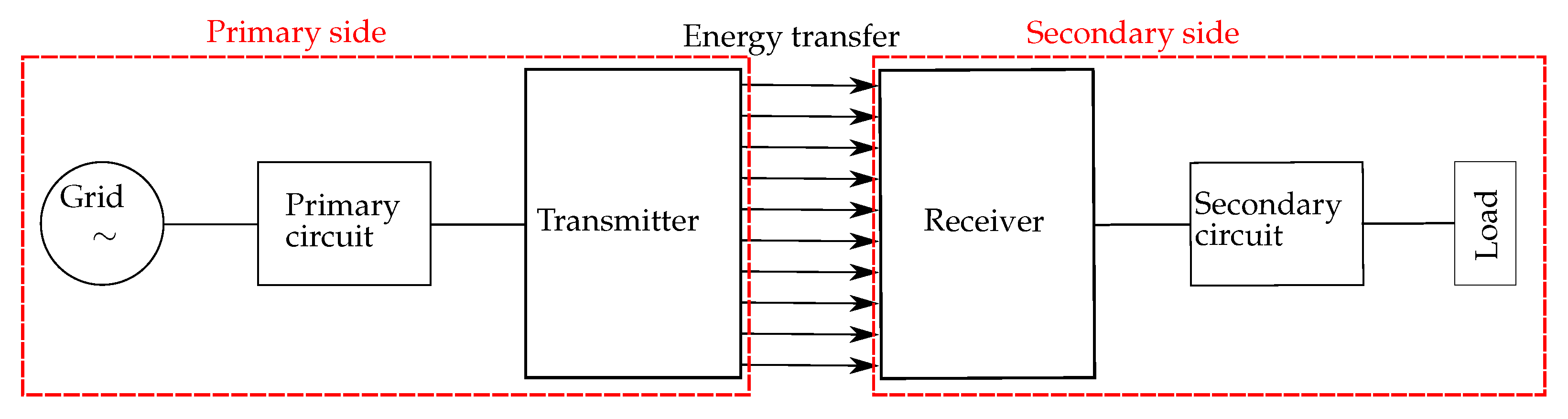
Electromagnetic wireless power transfer (WPT) is an emerging technology which permits electrical power to be delivered to a receiving device without any galvanic connection, such as a cable. This form of power transmission consists of two sides, separated by a medium, e.g., air, water or wood. To transmit energy wireless from one side to the other, a high-frequency signal is needed. This is achieved by converting the source voltage on the primary or transmitter side into a high frequency AC voltage and current, resulting in a wireless energy transfer through a medium. At the secondary or receiver side, the transmitted energy is ’captured’ and supplied to an electrical load (Figure 1).
- It allows for an improved user experience and convenience, in particular towards portable consumer electronics. It removes the hassle of connecting wires to the device.
- A WPT device does not need an open connector for charging. This allows for an entirely sealed (water and dust proof) device, increasing robustness and durability.
- Moreover, since a large charging connector is no longer necessary and battery size can be reduced, miniaturization is facilitated.
- WPT can also increase safety. Indeed, galvanic charging can generate sparks when (dis)connecting which can cause safety issues, in particular in hazardous industrial environments where combustible gasses are present.
- Mobile devices (such as smartphones, laptops or electric vehicles) function independent of the electric grid due to internal batteries. However, they regularly loose their mobility when they have to be connected for recharging. WPT would allow charging during the use of the device, e.g., an electric car can charge when driving on a highway [1] or smartphones could be charged at the office, even when they are in the pocket of the user [2]. In this way, mobility is improved.
- Wireless charging infrastructure is not abundant and requires a significant implementation cost.
- Compared to galvanic charging, WPT is less efficient.
- Safety and electromagnetic interference (EMI) should be accounted for. Often, more excess heat is produced, which can put strain on the components selection.
- WPT is generally more expensive than galvanic charging.
- WPT is limited to lower power exchange limits.
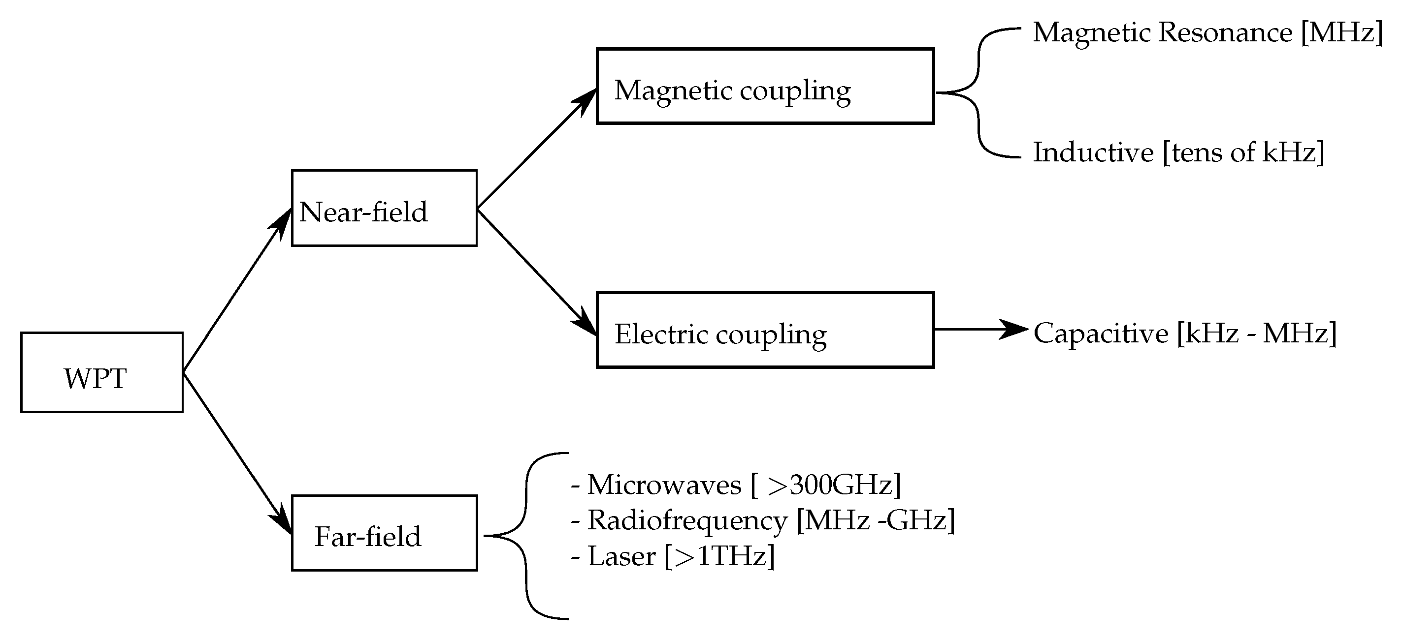
WPT systems can be categorized as in Figure 2. The first category within electromagnetic WPT is near field, which means that the wavelength of the electromagnetic (EM) waves is larger than the transfer distance between transmitter and receiver. The second category is far field, where the wavelength of the EM waves is smaller than the transfer distance [9]. In this paper, the focus will be on near field WPT in which two further subgroups can be distinguished, namely, on the basis of the dominating type of EM field: magnetic and electric coupling.
Due to these advantages, WPT is increasingly popular in a variety of applications, from low power consumer electronics to high power battery chargers [7,9,10]. This results in a rapidly growing market with an expected sales number of 2.2 billion pieces in 2024 [8,11]. The main share of the WPT market is based on the principle of inductive power transfer (IPT), a technology based on energy transfer via varying magnetic fields. In order to obtain energy transfer, two parallel coils are required, which are separated by a medium at a certain distance. IPT is based on Ampere’s law and Faraday’s law of induction: a varying current through a coil generates a time-varying field according to Ampere’s Law, this field is ‘captured’ by the receiving coil, and will induce a varying current in the coil according to Faraday’s law if the secondary side is closed.
Since Nikola Tesla’s first wireless power transfer experiments in 1891, numerous studies have improved IPT technology, so that commercial products achieve efficiencies of more than 85% [9,10,12]. However, IPT has certain disadvantages [1,13,14,15,16,17,18,19]:
- The varying magnetic field induces eddy currents which results in power losses, temperature rise and fire hazards.
- The magnetic fields easily radiate outside the WPT system, increasing EMI problems.
- For large coils (e.g., dynamic charging of electric vehicles), the conductive losses in the coils are significant, decreasing efficiency.
- IPT often requires litz wire to reduce the skin effect and ferrites to guide the magnetic fields. Both increase the weight, cost, and fragility of the system.
- The power transfer quickly drops when the coils are misaligned.
- Coils can be bulky, in particular for miniaturized integrated circuit applications.
An alternative to IPT is capacitive power transfer (CPT). It exploits the capacitive or electric coupling between two metallic plates with an alternating electric field, generating a displacement current. Compared to IPT, is has the following advantages [1,20,21,22,23]:
- The power losses due to eddy current are minimal.
- CPT is able to transfer power wirelessly through isolated metal objects.
- Contrary to IPT, some misalignment does not lower the power transfer significantly
- The coupling is realized by simple conductive plates (e.g., aluminum or copper), which are less expensive and heavy than litz wire coils. This simple setup also facilitates a high reliability and long lifetime compared to IPT. Moreover, no special shape is required, allowing for a versatile design.
- CPT is less voluminous than IPT, allowing its implementation into integrated circuits.
- Usually, less heat is produced compared to IPT with its high resistance windings of coils.
- The electric field lines of the CPT coupling are narrowers than the magnetic field lines in an IPT system. As a result, the EMI will usually be lower for short distance power transfer.
- It allows for a simple configuration for charging multiple receivers from a single transmitter.
Despite the given advantages, to our knowledge, CPT is not yet available on the market and research is lagging behind IPT [6,9]. This is due to some important disadvantages [24,25]:
- The low capacitance (and thus high impedance and low power density) of the capacitive coupling, which we will discuss further in detail.
- High frequencies and voltages are necessary, in particular for bridging larger distances. This imposes high requirements on the converter components.
- A high electric field between the primary and secondary side imposes strict safety regulation, e.g., object detection between the plates.
Table 1 contains a comparison of the most important properties of GPT, IPT and CPT. Based on this, an estimation can be made of which type of power transfer is suitable.
1.2. Literature Review
Research shows that CPT is viable for distances from 1 mm to tens of cm. Low power applications (<1 kW) include integrated circuits, portable electronics, biomedical implants, robots, drones, contactless universal serial bus (USB) and LEDs [4,20,29,30,31,32,33,34].
Over the last years high power applications become more viable due to the recent research into compensation circuits, suitable inverter stages and the plate structures. In particular, new high power applications such as underwater autonomous vehicles [18,35], railway applications [36,37] and the charging or powering of electrical vehicles [8,25,28,38,39,40,41,42,43,44,45,46,47] are some prominent examples. In particular, the dynamic charging ability of CPT is considered promising [1].
Table 2 presents a number of practical setups which are described in the literature, with improvements from new plate structures to bidirectional energy transfer in CPT.
In previous review papers, the main focus was limited to compensation networks [24,52], comparison of IPT and CPT [9,10] or an overview of CPT with emphasis on the mathematical equations [20]. The purpose of this paper is to link the theoretical concepts to some practical cases and to indicate where further research is required to take next steps towards a marketable product.
1.3. Contribution and Paper Organization
This paper will give an overview of the current state-of-the art of the CPT technology. First, we focus on the capacitive coupling itself (Section 2). In this section, an overview is given on how the capacitive coupling is achieved and how it can be calculated by hand as well as with simulation programs. Next, we consider different plate topologies in Section 3 and the various possibilities for compensation networks in Section 4. Finally, the converters are discussed in Section 5.
This review paper contributes to the state of research by:
- Providing a holistic overview on CPT modelling
- Taking multi-plate structures, compensation circuits and power electronic converters into account.
- Providing recommendations for the choice of CPT structures based on the application.
- Summarizing challenges, limitations and further improvements.
2. Capacitive Coupling Model
Usually, the capacitive coupling of a CPT system is represented as a pair of capacitors in series as shown in Figure 3. However, this representation is not always suited for simulation purposes. First, it makes it difficult to analyze primary and secondary sides separately as they are connected by the equivalent coupling capacitor. Second, practical CPT bears undesired leakage and cross-couplings. These parasitic capacitances are not taken into account in this simple model. More complex models overcome these drawbacks, allowing them to go deeper into the system parameters of both the primary and secondary sides [53,54].
2.1. Pi-Model
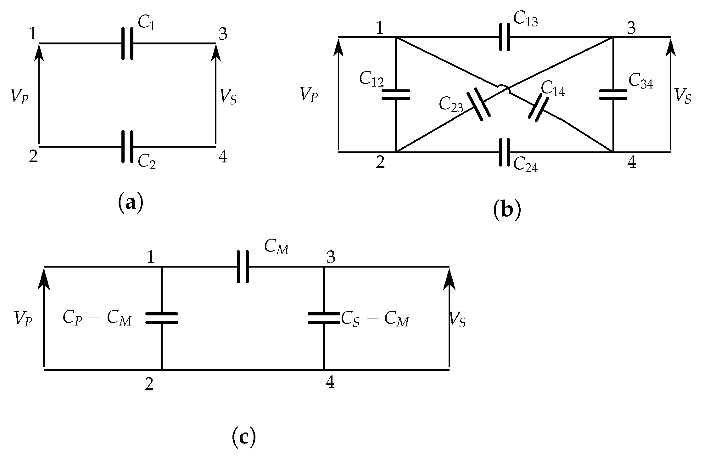
The physical structure of Figure 4a can be replaced by the equivalent model of Figure 4b, which takes into account the leakage and cross-coupling capacitances [53]. It can be transformed into a general pi-model, as shown in Figure 4c. The equivalent circuit divides the CPT system in a primary and secondary side in which the primary and secondary capacitances are denoted as and . The mutual capacitance describes the coupling strength between transmitter and receiver. In practice, , and can be derived by measurements with an accurate LCR-meter [54].
We call plates 1 and 2 the plates that are connected to the primary side; plates 3 and 4 are connected to the secondary side. In Figure 4b, the main coupling capacitances are given by and . The model explicitly contains the leakage capacitances and as well as the cross-coupling capacitances & . The coupling between the plates is based on the ratio between the mutual capacitance and storage energy of the plates.
This capacitive coupling model can be represented by the equivalent circuit of Figure 4c. The parameters , and can be determined on the basis of the energy balance. The charges and at primary and secondary side, respectively, are [54]:
with and the voltages as indicated in Figure 4.
Given (1), the primary capacitance can be calculated by short-circuiting the secondary side ( = 0) [54]:
Similarly, the secondary capacitance can be calculated by short-circuiting the primary side ( = 0) [54]:
The mutual coupling capacitance is given by [54]:
Note that is independent on the leakage capacitances. A general model is represented in Figure 5, in which the leakage capacitances are separated from the wireless link, since they do not contribute to the coupling.
The mutual coupling ranges to infinity and does not reveal much information about the quality of the coupling itself. For this reason, the capacitive coupling coefficient is introduced. This ratio is a figure of merit for the coupling strength, taking parasitic coupling into account. It is defined as the ratio of the coupled energy to the stored energy of the electromagnetic field, and can thus never exceed unity in magnitude: 0 1. It equals [53,54]:
This expression can be further simplified for the case that primary and secondary plates are symmetric. This allows a simplification for main couplings, and , and the cross-couplings, and [54]:
which results is in a simpler expression for capacitive coupling coefficient [54]:
Equation (8) shows that under ideal conditions, when there is no cross-coupling between plates, is equal to one. When no cross-coupling is present, the primary, secondary and mutual capacitance equal half of the main capacitance :
When the cross-coupling is equal to the main coupling , the coupling coefficient becomes zero. This implies that the cross-coupling will entirely eliminate the main coupling according to the cross-coupling cancellation effect. There will be no more coupling present between primary and secondary plates.
2.2. Two-Port Network
When the plate structures become more complex, as is the case of, e.g., six-plate structure or the matrix structure, a pi-model is no longer suited to analyze the characteristics of the coupling structure [50,55]. Moreover, determining or measuring the mutual capacitance between any two plates for a complex arrangement is far from straightforward.
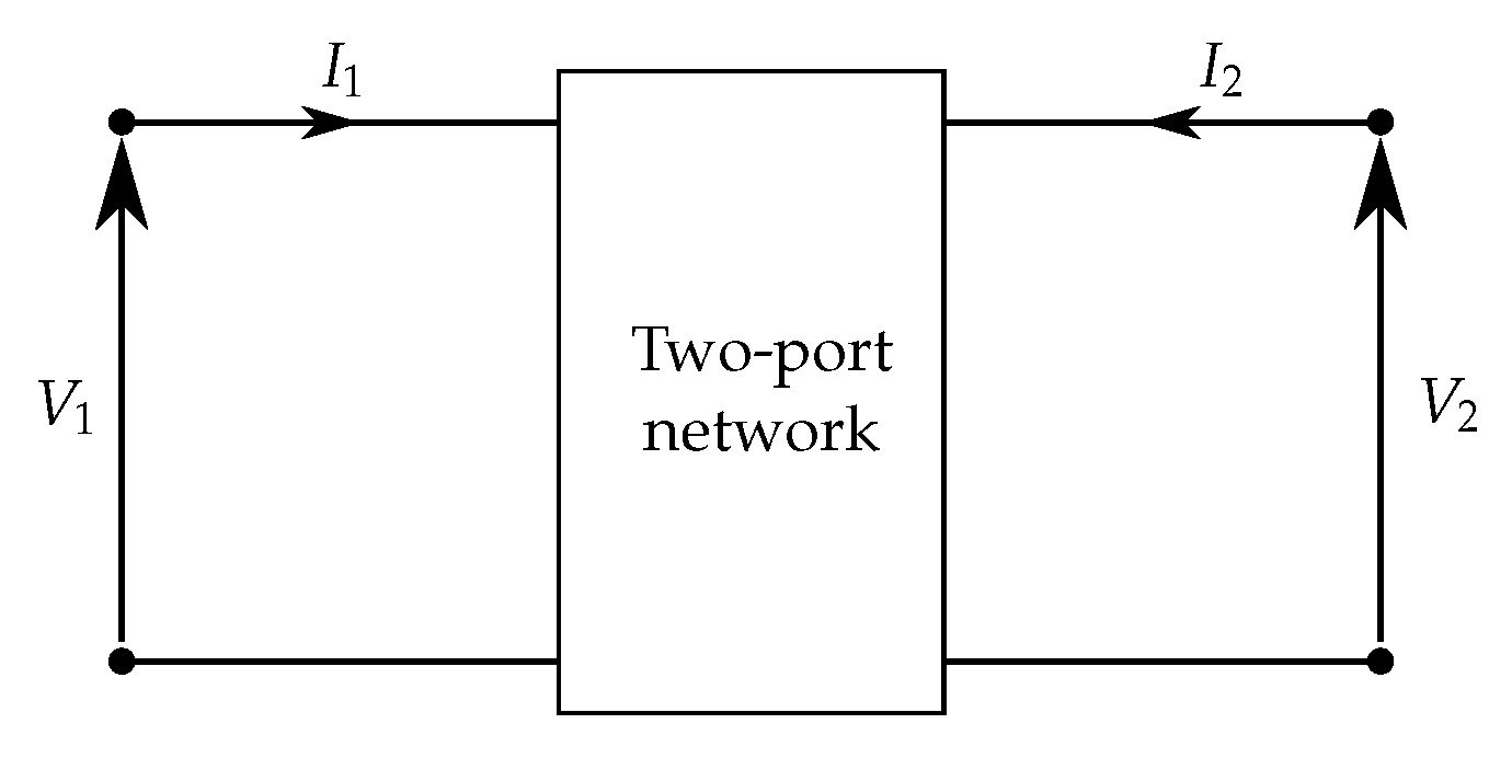
One way to overcome these difficulties is to represent the WPT by a two-port network: it consists of a black box with two pairs of terminals, as shown in Figure 6; the first port represents the input or primary side; the second port corresponds to the output or secondary side. These two ports provide terminal voltage-current characterizations of the coupling structure [56]. Two-port networks can serve a dual purpose. On the one hand, they simplify the analysis of electrical circuits; on the other, they can be the basis for transient simulations. The electrical behavior of the black box can be characterized by a single matrix, e.g., the admittance matrix Y:
with V and I the current and voltage matrices of the ports.
Consider for example the six-plate structure of Figure 7a that encompasses 15 capacitances. Plates , , and are directly connected to the source or load. The plates and are not connected to a closed circuit, thus no current flows through those plates. The admittance matrix Y that describes this structure can be determined from analytical calculations, full-wave simulations or measurements [57]. The admittance matrix for the corresponding lossless network can be given by the equivalent network of Figure 7b, for which [50]:
In this network, the coupling is represented by two current-dependent sources at primary and secondary side, dependent on the angular frequency and the voltages. The parasitic capacitances are given by and .
3. Plate Structures
To transmit and capture electric fields, at least two metal plates are needed to achieve capacitive power transfer. These plates can take any shape, often rectangular or concentric. The plate structure largely determines the mutual capacity of the plates and thus the coupling coefficient . Some configurations can affect parameters such as the electric field emissions, compensation networks or misalignment [37,39,50,58,59].
3.1. Two-Plate Structure
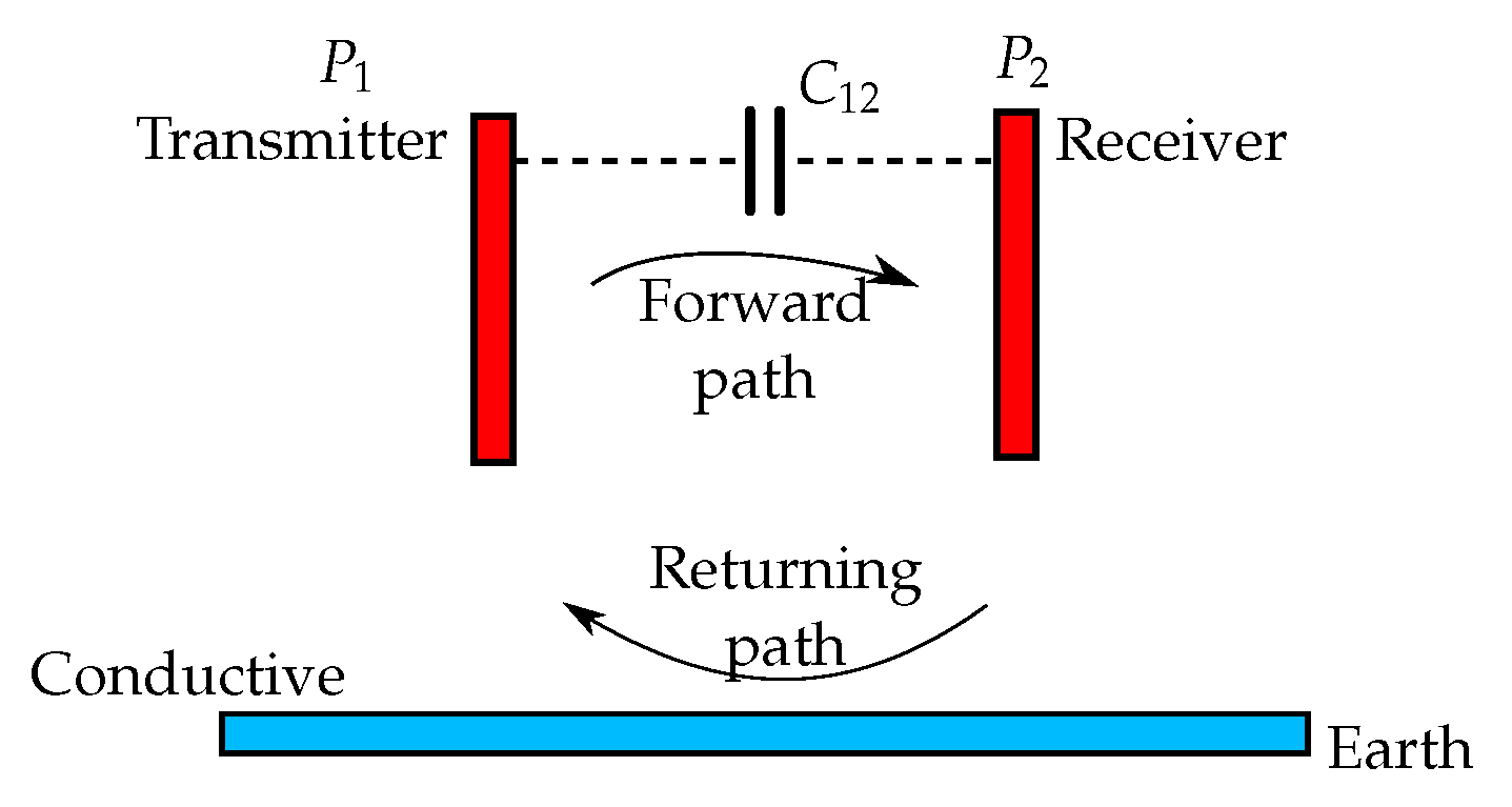
A two-plate capacitive plate structure as shown in Figure 8 is very similar to the construction of a normal capacitor with its two plates; one plate is connected to the transmitter and the other plate to the receiver. The return path for the current to close the circuit is not a wireless CPT setup, but a conductive path, e.g., the earth itself.
In railway applications, it is even possible to create a recurring current path via the wheels connected to the track; this setup can replace the maintenance-intensive pantograph of classic railway applications [37]. For charging electric vehicles, the parasitic capacitance between the chassis of the vehicle to be powered and the earth ground can function as current path to close the circuit [39]. With this arrangement, a good connection between the chassis of the system to the earth is important. According to regulation [60], the voltage between chassis and earth potential should be reduced to safety level. In practical setups, the earth potential will connect to a ground side plate to reduce the conductive loss [39].
The main advantage of a CPT system with two-plate structure is the simplified hardware. Moreover, a two plate structure with an LCLC-compensation network has less impact on efficiency due to misalignment [59]. However, more research is needed, e.g., in electric vehicle applications, to reduce the contact voltage between chassis and earth potential which is the main disadvantage and hazard of this plate structure [39].
3.2. Four-Plate Structure
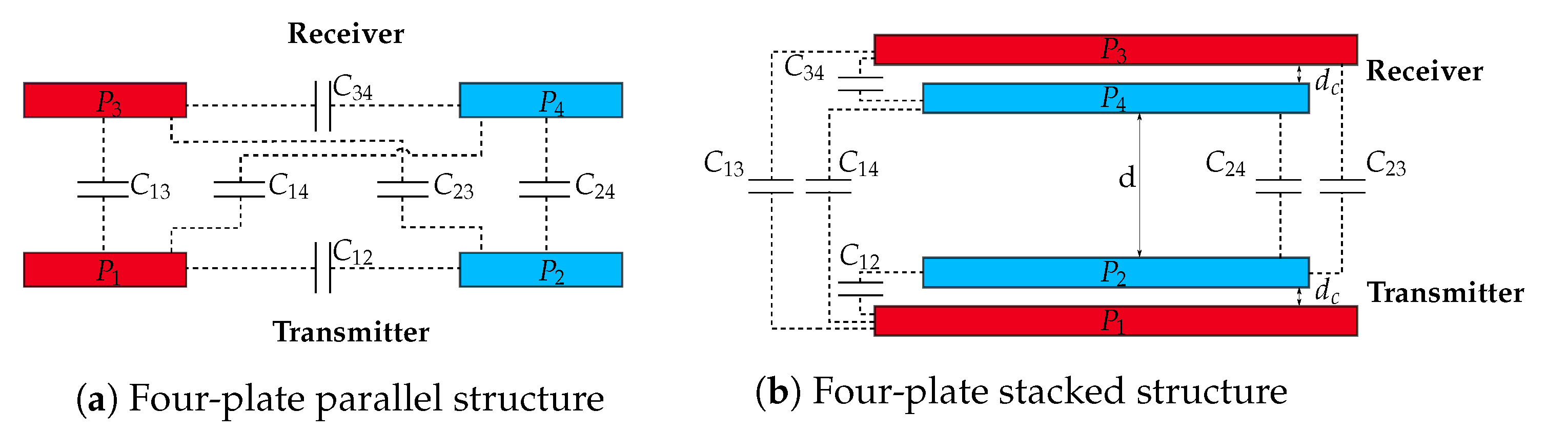
The most common plate structure of CPT is the four-plate structure. The transmitter consists of a positive and a negative plate as well as the receiver. The four-plate structure comprises of two main coupling capacitances and four leakage capacitances and can be configured either stacked or in parallel, as shown in Figure 9 [20].
The parallel structureis the most common CPT plate structure, as show in Figure 9a. This systems consists of four plates with two parallel pairs of two plates. When the plates are placed close to each other and well-aligned, the main coupling will dominate the resulting capacity. However, when one of these conditions is not fulfilled (e.g., large distance between the plates or a significant misalignment), a larger parasitic coupling is created, resulting in a lower capacitive coupling quality.
The stacked structure was introduced in [45] with the aim of making the set-up more compact. The coupler structure, as shown in Figure 9b, has larger outer plates and and smaller inner plates and to maintain the coupling between the outer plates. Because of the vertical structure, it is resilient to rotary misalignment. Overall, the capacitive coupling coefficient of the stacked structure is lower than the of a parallel structure due to smaller main capacitances. This results in a system that is more influenced by the cross coupling capacitances, which are larger due to the compactness of the design [6,21,45,46,61].
3.3. Six-Plate Structure
The six-plate or shielding coupling structure, as shown in Figure 7a, is in fact a four-plate parallel coupling structure extended with a shielding part of two large plates. The four plates , , and provide the power transfer between primary and secondary and are directly connected to the compensation circuits. The two extra shielding plates are large enough to cover the inner four-plate coupling structure and are not directly connected to the system. They are only coupled via parasitic capacitances and are floating because they not participate in de power transfer. The main purpose of the extra shielding part is to reduce the electric field emissions. The studies [47,50,55,62] have shown that this six-plate structure improves the system safety and efficiency. As there are two more plates, the coupling model of the six-plate structure consists of fifteen capacitances which makes the analysis of the coupling more complicated as discussed in Section 2.2.
3.4. Matrix Structure
In coupling structures such as the two-, four- or six-plate, any misalignment causes a decrease of the capacitive coupling. A change in the capacitive coupling values causes a change in the resonance frequency of the system which in turn ensures a detuning of the system and results in an output voltage drop, which in the worst case drops to zero.
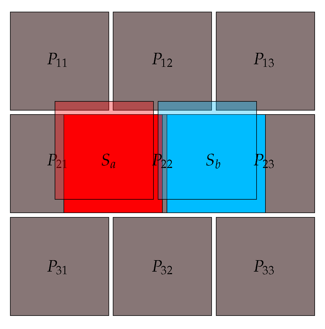
A matrix coupling structure, which may consist of row, column or hexagonal structures, can mitigate the misalignment [48,58,63,64]. Consider for example the matrix structure of Figure 10 and assume that the receiver plates are positioned at their least optimal location: the secondary plates and are coupled by primary plates , and . In this configuration, is coupled with both the secondary plates, which will cancel each other. As a result, the secondary capacity will be minimal and equal:
with the equivalent capacity of the coupling formed by and .
In the most optimal receiver position, will increase until its maximum, i.e., when is fully coupled with . This results in:
Assuming a repeating matrix structure, the coupling will always be within 0.25 to 0.50, whatever the misalignment. The minimum value can be increased by increasing the dimensions of the primary matrix, resulting in less variation when the receiver moves [58].
This matrix structure can be advantageous for applications where large misalignment is possible, but its implementation is more difficult, due to the necessary complex control logic to adjust the plates and their corresponding parasitic and main capacitances.
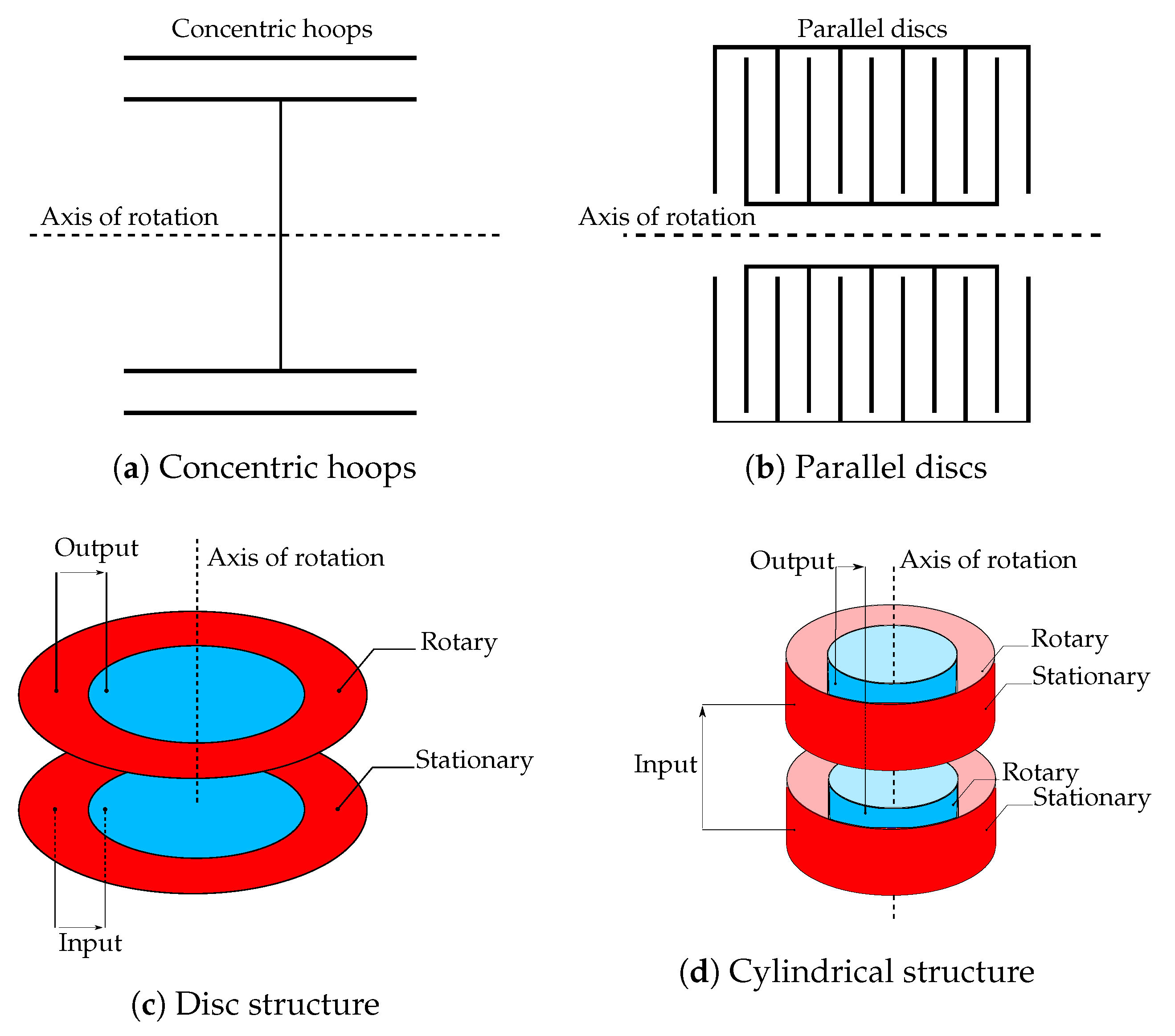
3.5. Concentric Structure
Wireless power transfer is advantageous for linear moving devices since it gives the designer more degrees of freedom and reduces the maintenance cost of the charging contacts. But for rotating devices such as motors or robots, it can really be a breakthrough. Currently, some rotating robots can only rotate to a limited extent due to the wiring [65]. When using WPT or more specific CPT, this could be a continuously rotating device, allowing the robot to perform more tasks. With CPT in motor systems, the mechanical slip rings can be replaced by metal plates which form the capacitive coupling [66].
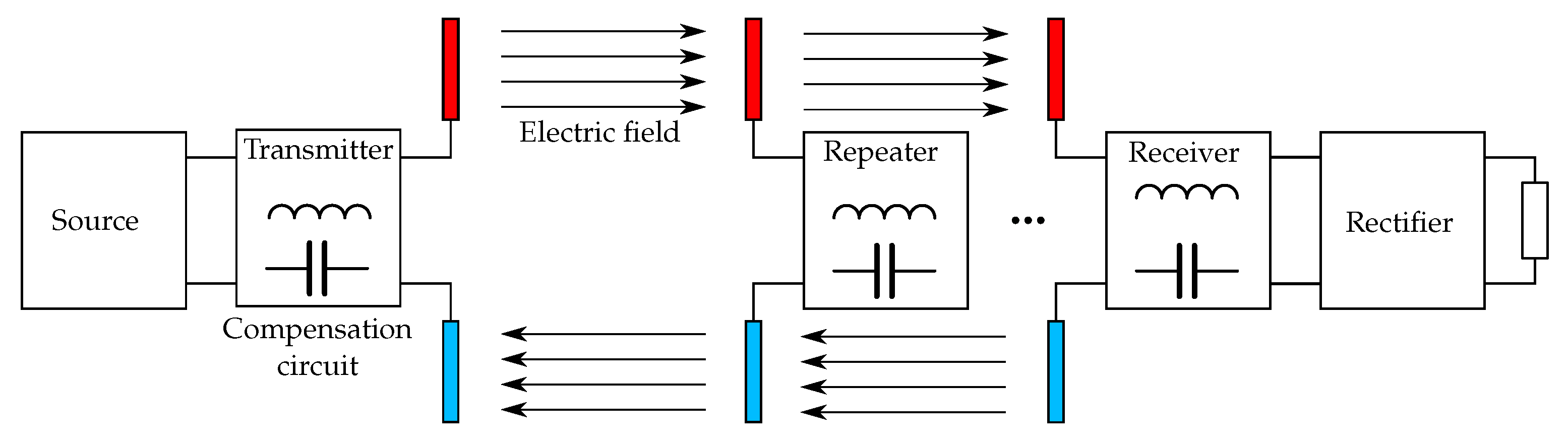
3.6. Electric Field Repeater
The aforementioned structures are capable of transmitting energy over a distance of a few millimeters to about ten centimeters. To cover greater distances, an electric field repeater can be used [20,49,69]. This repeater or relay is not galvanically connected to the transmitter or receiver and allows for an intermediate extension of the electric field. This technology is first discussed in [49] and is a new research topic in CPT as well as IPT [20].
Figure 12 shows an electric field repeater based on the four-plate parallel coupler structure. As the distance increases, more repeater stages can be inserted. With power losses in every stage, the transfer efficiency drops which forms the main challenge of these systems.
4. Compensation Networks
The main challenge of CPT systems is the low coupling capacitance between the plates (often in the range from tens to a few hundred picofarad) between the plates. In order to realize a decent power transfer at such low coupling capacitances, two options are possible: increasing the frequency and/or magnitude of the voltage feeding the primary side. However, high frequencies lead to significant losses in the converter. High voltages increase risks and put constraints on the component requirements. The voltage at the coupling capacitors is limited by, on the one hand, the breakdown voltage of the medium and, on the other, the safety regulations regarding electric field strengths. Moreover, high frequencies, as well as high voltages, complicate the achievement of efficient soft-switching at the converters.
In order to reduce the switching losses, an inductive compensation network can be added to create resonance at a lower frequency, resulting in a soft switching operation of the converter and a better coupling between the primary and secondary plates [20,44,70,71]. At the primary side, the most important goal of the compensation network is to serve as a voltage booster, in order to cross the high impedance caused by the low capacitances at the wireless link. Obviously, as a result, the current is lowered at the coupled capacitances. At the secondary side, the current can be boosted (and the voltage lowered) by a compensation network to power the load.
Another reason to implement compensation circuits is to increase the quality factor Q (which corresponds to the ratio of the initial energy stored in the resonator to the energy lost in one cycle of the oscillation) of a CPT system. Compared to IPT systems, the Q-factor is much lower in CPT systems. In practice, for a CPT system with no compensation circuits the Q-factor is smaller than one for normal loads in parallel tuning, which means that the output voltage is lower than the input voltage [70].
Compensation circuits can also serve as a tuning method for the coupled capacitors. In the next sections, some frequently used compensation topologies are discussed.
4.1. L Compensation
The inductor compensation network is the most simple and widely introduced in high and low power applications. In CPT, it is also called a traditional compensator [24,66,67,72]. As example, we consider five common used topologies for a CPT system with an inverter in combination with an L compensation network:
- non-resonance (N-N)
- primary resonance (S-N)
- secondary resonance (N-S)
- series-series (S-S)
- series-parallel (S-P)
A series compensation circuit provides a voltage gain at resonance, which is required to obtain high voltages at the transmitter plate, while a parallel compensation circuit provides a current gain to supply the load. Figure 13 shows the above mentioned compensation circuits topologies. Figure 13b depicts the primary resonance compensation circuit; for secondary resonance, the coil L should be positioned to the secondary side in series with the load.
Since the primary and secondary side are connected by means of the capacitive coupling, one would expect that the series inductor can be placed on either side of the circuit without difference. However, it was shown [70] that when good misalignment tolerance and power factor are desired, the inductor must be placed at the secondary. When misalignment is not an issue, it may be placed at the primary.
In [71], a comparison is made of the five different topologies for a simple L compensation circuit. They tested the aforementioned topologies at a resonance frequency of 450 kHz and each at their optimal load for efficiency (power gain) maximization. It was shown that the inductor’s location does play a role. Whereas an efficiency of about 63% was measured for N-N and S-N topology, a value of nearly 95% was reached for the N-S, S-S, and S-P topologies. Furthermore, for their setup, an N-S and S-S compensation network is ideal a low load area application while an S-P is suited for higher loads.
In particular, for high-power and large distance applications, the disadvantages of L compensation circuits become more significant. Due to the fact that capacitive coupling can only achieve small capacitances, a large inductor will be required to compensate. In addition, by using a single inductor compensation, the system is very sensitive for changes in parameters such as misalignment or distance between the plates.
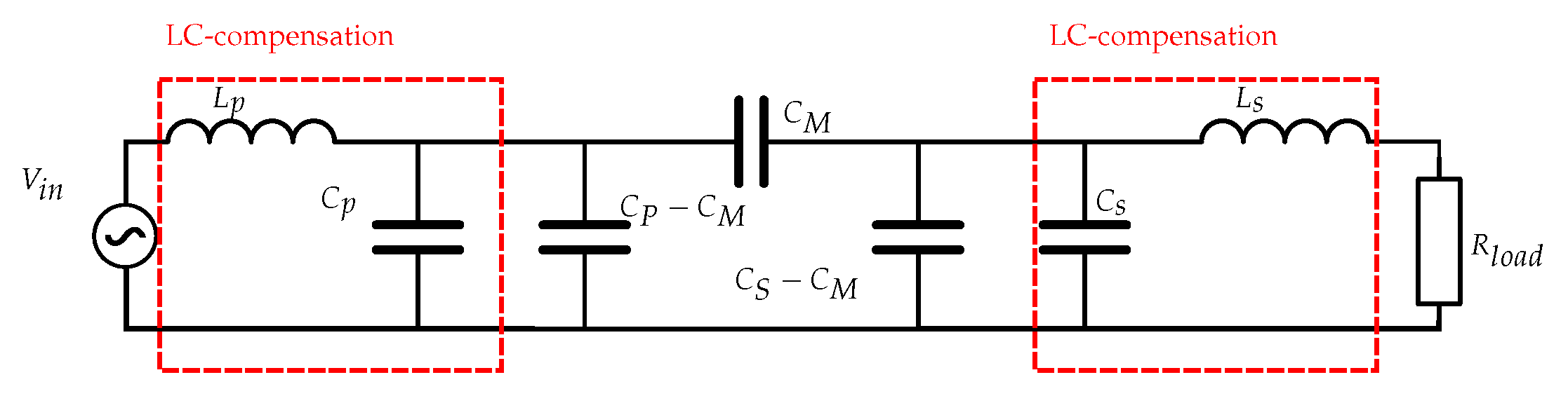
4.2. LC Compensation
One way to tackle the small coupling capacitance of CPT is adding extra capacitances at the compensation circuit of the primary and secondary side. By adding extra capacitances in parallel over the mutual capacitance, the equivalent capacitance of the CPT system increases. This allows for larger distances between primary and secondary plates and results in less sensitivity to distance variations [20]. At a fixed mutual capacitance, the equivalent coupling capacitance (and thus the resonance frequency) will be largely unchanged. An example circuit of using LC-compensation circuits is shown in Figure 14 [28,43].
Despite the positive effects of adding capacitors to the compensation circuits, there are still challenges at high power transfer at large distances. Indeed, by increasing plate distance and keeping the output power constant, the coupling coefficient and efficiency decreases. This implies that the system input power will increase which in turn will cause more voltage and current stress on the components [20,28].
A solution to these problems is the combination of L and LC compensation networks, i.e., a multistage L-matching network [72,73]. A multistage L-section matching network can be constructed by cascading stages to achieve a certain voltage or current gain. These networks will be discussed in the following section.
4.3. Multistage L-Section Networks
By combining the L and LC compensation networks, new compensation topologies can be composed depending on what is to be achieved. When the L-section stages in multistage matching networks are designed for resistive loads, they only provide gain without compensation [74,75]. Analytical approach were introduced to enable the use of L-section multistage matching networks at complex loads and input impedances to provide gain as well as compensation [72,74]. In this framework, three quantities are used to define an L-section stage:
- Current or voltage gain;
- Load impedance characteristic;
- Input impedance characteristic.
Achieving voltage or current gain depends on the structure of the L-section as shown in Figure 15. In Figure 15a, a network is implemented at the primary side to achieve voltage gain whereas in Figure 15b, the L-section is implemented at the secondary side to realize current gain.
Multistage L-section networks are most suited for high power applications because they can be designed to achieve a high voltage and/or current gain at high efficiencies.
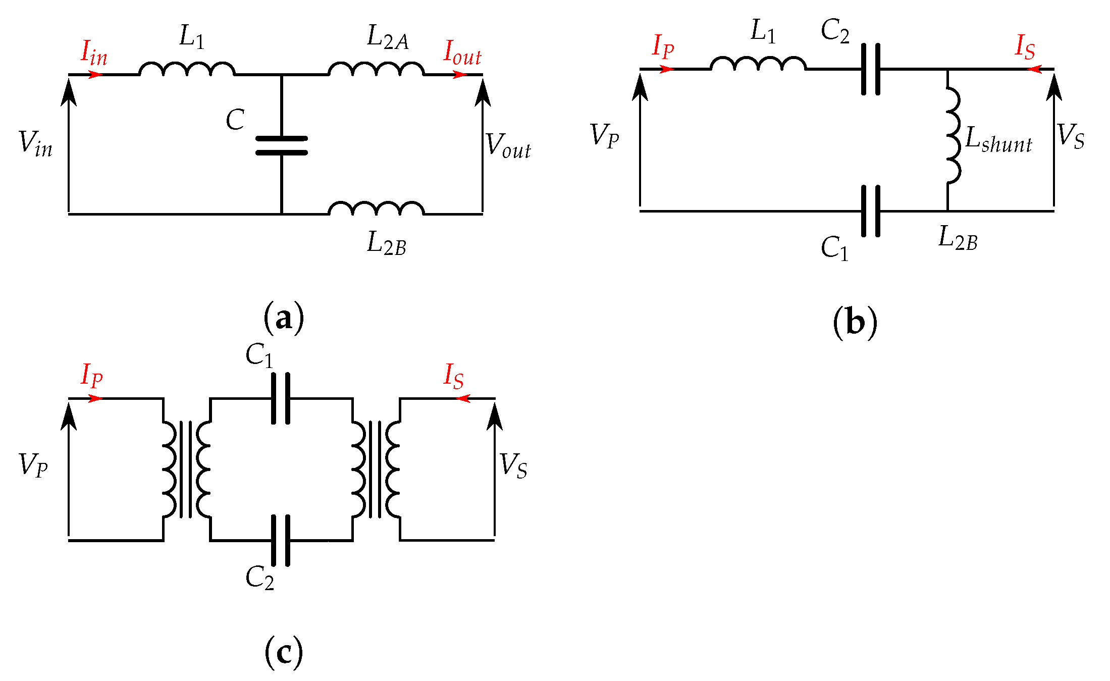
4.4. Other Compensation Topologies
Variations on the above topologies exist to tailor the requirements of the application (Figure 16). For example, a composite LCL configuration allows for both increasing or decreasing the voltage, depending on the required operation regime. It has the ability to operate in zero voltage switching conditions outside resonance and is able to increase the power factor at the interface with a low EMI [63,76,77,78]. A modified LLC topology utilizes a shunt inductor on the secondary side to be able to operate outside resonance conditions, increasing the versatility of the CPT system [67,76,79]. In addition, transformers on the primary and/or secondary side can realize the required voltage change and serve as impedance transformation [80,81,82].
5. Converters
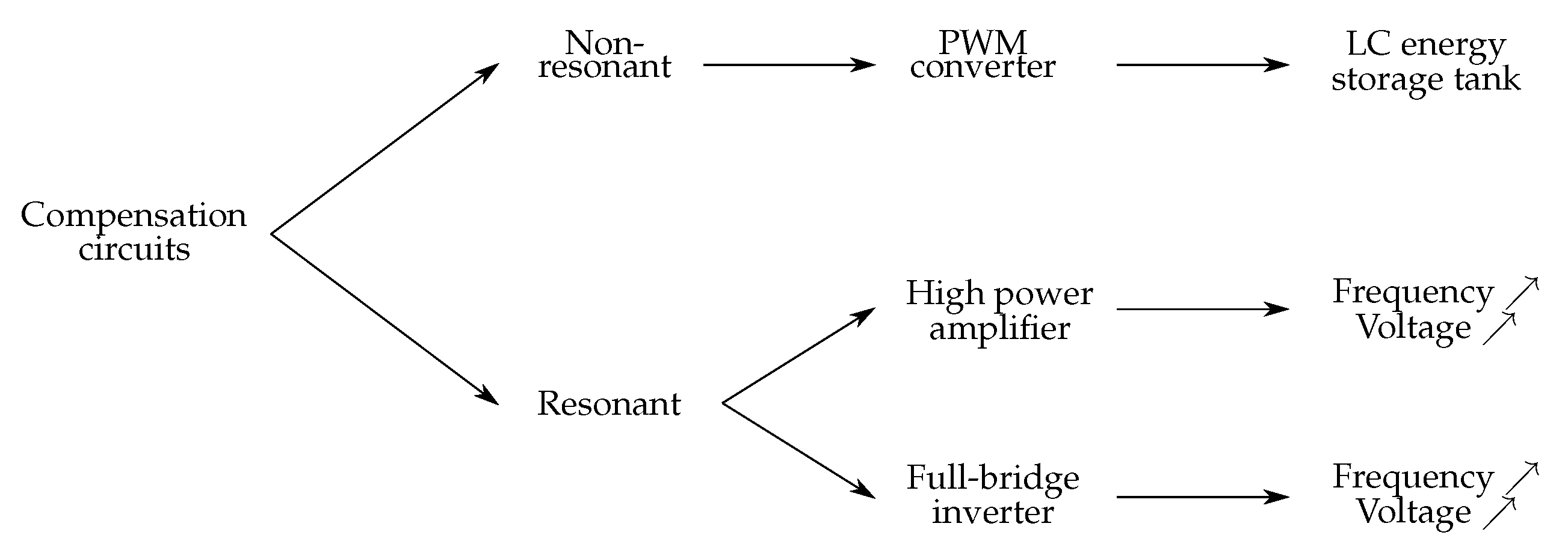
An efficient converter to generate AC from a DC source is important to minimize the losses for the wireless power transfer. Figure 17 depicts the relationship between the compensation circuits and the high frequency converter topology. Herein a classification is made of three converter topologies [63], which will briefly be discussed in the following sections:
- Pulse width modulation (PWM);
- Power amplified based converter;
- Full-bridge inverter.
5.1. PWM Based Converter
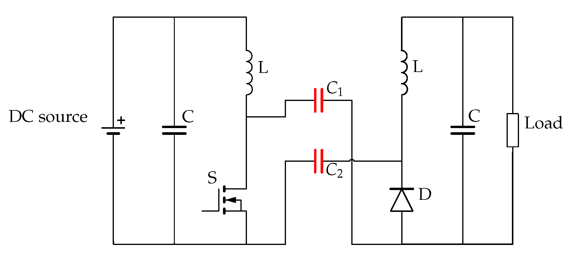
The PWM converter is a single switch converter and has several different circuit topologies, such as: buck-boost, Ćuk, SEPIC, ZETA and push-pull converters [43,52,63,83,84]. Those PWM converter topologies use an LC storage tank which can be modified to create a primary and secondary side. In general, the primary side contains a high-side inductor in series with a low-side switch and the secondary contains a high side inductor in series with a low-side diode. Lastly, the coupling between the primary and secondary is done by using metal plates which will fulfill the function of the capacity in the LC storage tank [83]. Figure 18 shows a modified Ćuk converter which is used in [83] as an example of single active switch converters in kilowatt scale CPT.
The PWM based converter is less sensitive to the variations of system parameters such as change of coupling capacitance due to misalignment or changing distance between transmitter and receiver. If the components are specified large enough, continuous-current working mode can be guaranteed at the desired efficiency and power output despite system parameter changes. This converter topology has limitations due the use of only one active switch. The maximum output power is limited to the maximum specifications of the active switch which results in short distance low power applications. Another negative aspect of using a single active switch is that zero voltage switching can not be accomplished under all load conditions which results in increasing EMI [43,52].
5.2. Power Amplifier Based Converter
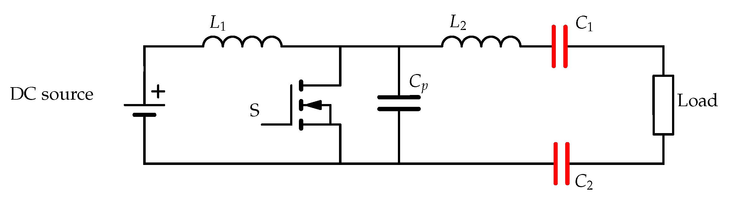
High frequency power converters are used in several applications, e.g., home theater systems (audio) and motor drives. Some of these types of converters are also suitable for CPT, such as: class D, class E, class EF and class converters [85,86,87,88,89,90,91,92,93,94]. By using a resonant LC tank, these converters can be designed to operate in zero voltage switching (ZVS) mode at high switching frequencies. This improves the system efficiency and reduces the size of the components [43,94]. Figure 19 shows a modified Class E converter for a CPT.
The main drawback of power amplifier based converters is the sensitivity to system parameter changes. In practice, misalignment is a common issue: it decreases the coupling capacitance which increases the required resonance frequency of the system. This results in higher switching losses in the converter and can even lead to the loss of ZVS mode. Compensation circuits increase this sensitivity even more. For this reason, these types of converters are commonly used in low power applications which are ‘static’ [85,95].
5.3. Full-Bridge Inverter
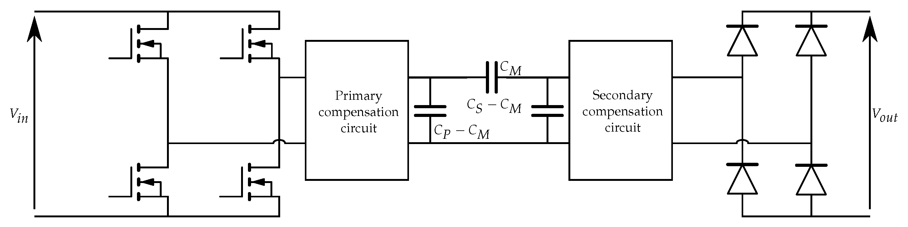
Figure 20 shows a CPT system with full bridge inverter which are the most common inverters to provide AC-signals to the CPT transmitter because of its easy parameter design and robustness [85]. An additional advantage of the full-bridge inverter is the possibility of high input voltages and low voltage stresses over the switching components in comparison to other inverter topologies [85,96].
At the primary side of a full-bridge CPT system, four switching devices, usually metal-oxide-semiconductor field-effect transistors (MOSFETs), are used to transform DC-signals to AC-signals. Those MOSFETs are controlled by PWM signals, by changing the duty cycle and switching frequency, the output power of the system can be regulated. At the secondary side, a rectifier is used to rectify the AC-voltage to supply the load.
6. Challenges
6.1. CPT at Variable Loads
The biggest challenge of CPT is the low coupling capacitance, this is already partially countered by several types of compensation circuits. Studies in the literature present their compensation circuit at a certain fixed load. The main problem in practice is load dependency, a variable load such as a robot, makes short movements and thus draws peak currents. Every load change changes the voltage output of the compensation circuit which may cause the capacitive coupling to become less effective. A solution for variable capacitive coupling, e.g., variable charging distance, in [97] is suggested. The authors state this can be addressed by adjusting the switching frequency.CPT should be investigated with variable loads using the models presented in this paper.
6.2. Transfer Medium
The majority of WPT systems studied, use air as medium between transmitter and receiver. In reality, there are applications where another medium can be used. Literature is also inconclusive as to which medium is best to use and how it acts at high voltages and high frequencies as discussed in [98]. Media such as wood, stone or thermal isolation material should be assessed for their effect on capacitive coupling.
6.3. Safety Issues
Safety is the most important factor in commercializing a product. At a CPT system, the main concerns are the high voltages present on the metal plates and the electric field emissions.
As mentioned earlier in this paper, CPT system can achieve hazardous voltages up to several kV because of the compensation circuits. This voltage level is lethal for human body when touched. For this reason, the capacitive coupler must be appropriately insulated, for the chosen applications.
Electric field emissions are included in international standards, for example the IEEE C95.1 states that the maximum electric field strength may be 614 V/m [60]. Ref. [50] created a simulation model of a 2.0 kW 1 MHz CPT system. The authors simulated a four-plate as well as a six-plate CPT system, which resulted in an electric field between the transmitter and receiver of 27 kV/m. Adding extra shielding plates reduces the safety range, according to standard IEEE C95.1 [60], from 1 m with the four-plates structure to 0.1 m with the six-plate structure.
7. Discussion
This review paper started with an explanation of the main components of the capacitive power transfer model. Insights into capacitive coupling were gained using the Pi-model. This model is necessary to understand the capacitive coupling but towards simulations and calculations it is required to work further with two-port networks.
The selection and implementation of the other components of a CPT system, plate structure, inverter topologies and compensation networks, depends on the application for which the CPT system is intended. In order to make the right choices, the following parameters should be known in advance:
- Implementation area: based on this, safety area restrictions can be imposed. For example, an installation with people in the vincinity will require a narrow safety area and will therefore prefer a six-plate structure, whereas a fully automated warehouse can provide a large safety area where a four-plate structure suffices.
- Output power: goes along with the choice of inverter type. Higher power rating, above 1 kW, generally demands a full-bridge inverter.
- Distance between transmitter and receiver: This parameter affects the choices of the inverter type and compensation circuits. For distances greater than 10 cm, multistage L-section networks are preferred.
Knowing these parameters, the capacitive coupling can be modeled as described in Section 2 in this paper. Further design steps can be taken using computer simulations.
8. Conclusions
In this paper, an overview was given on the current state of research of capacitive wireless power transfer. Its advantages and drawbacks, compared to inductive wireless power transfer, were highlighted. The wireless link was approached by a pi-model and an equivalent two-port network model. The most simple and common plate topology, the four-plate configuration was discussed, next to more recent improvements on the plate topology, including six-plate, matrix and concentric setups. It was also concluded that electric field repeaters can be used to extend the power transfer distance. To mitigate the very low coupling capacitance of the wireless link, compensation circuits are inserted into the network. The most common compensation topologies were reviewed. Finally, pulse width modulation, power amplified based and full-bridge inverters were listed that can drive the capacitive link. The rising research on capacitive power transfer highlights its potential for future applications.
Author Contributions
Conceptualization, C.L., B.M., M.K.; investigation, C.L.; writing—original draft preparation, C.L.; writing—review and editing, M.K., B.M. All authors have read and agreed to the published version of the manuscript.
Funding
This work has been supported by Internal Funds KU Leuven.
Institutional Review Board Statement
Not applicable.
Informed Consent Statement
Not applicable.
Data Availability Statement
Not applicable.
Conflicts of Interest
The authors declare no conflict of interest.
Abbreviations
The following abbreviations are used in this manuscript:
| GPT | Galvanic power transfer |
| WPT | Wireless power transfer |
| IPT | Inductive power transfer |
| CPT | Capacitive power transfer |
| EMI | Electromagnetic interference |
| EM | Electromagnetic |
| PWM | Pulse width modulation |
| MOSFET | Metal-oxide-semiconductor field-effect-transistor |
| ZVS | Zero-voltage-switching |
| D | Diode |
| S | Switch |
| C | Coupling capacitance [F] |
| L | Inductance [H] |
| q | Electric Charge [C] |
| I | Current [A] |
| V | Voltage [A] |
| Angular velocity [rad/s] | |
| Q | Quality factor |
| kE | Capacitive coupling coefficient |
| N-N | Non-resonance |
| S-N | Primary-resonance |
| N-S | Secondary-resonance |
| S-S | series-series |
| S-P | series-parallel |
References
- Zhang, H.; Lu, F.; Mi, C. An electric roadway system leveraging dynamic capacitive wireless charging: Furthering the continuous charging of electric vehicles. IEEE Electrif. Mag. 2020, 8, 52–60. [Google Scholar] [CrossRef]
- Jadidian, J.; Katabi, D. Magnetic MIMO: How to charge your phone in your pocket. In Proceedings of the 20th Annual International Conference on Mobile Computing and Networking, Maui, HI, USA, 7–11 September 2014; pp. 495–506. [Google Scholar]
- Haerinia, M.; Shadid, R. Wireless power transfer approaches for medical implants: A Review. Signals 2020, 1, 209–229. [Google Scholar] [CrossRef]
- Jegadeesan, R.; Agarwal, K.; Guo, Y.X.; Yen, S.C.; Thakor, N.V. Wireless power delivery to flexible subcutaneous implants using capacitive coupling. IEEE Trans. Microw. Theory Tech. 2016, 65, 280–292. [Google Scholar] [CrossRef]
- Minnaert, B.; Thoen, B.; Plets, D.; Joseph, W.; Stevens, N. Wireless energy transfer by means of inductive coupling for dairy cow health monitoring. Comput. Electron. Agric. 2018, 152, 101–108. [Google Scholar] [CrossRef] [Green Version]
- Lu, X.; Wang, P.; Niyato, D.; Kim, D.I.; Han, Z. Wireless Charging Technologies: Fundamentals, Standards, and Network Applications. IEEE Commun. Surv. Tutor. 2016, 18, 1413–1452. [Google Scholar] [CrossRef] [Green Version]
- Covic, G.A.; Boys, J.T. Inductive power transfer. Proc. IEEE 2013, 101, 1276–1289. [Google Scholar] [CrossRef]
- Minnaert, B.; Mongiardo, M.; Costanzo, A.; Mastri, F. Maximum efficiency solution for capacitive wireless power transfer with N receivers. Wirel. Power Transf. 2020, 7, 65–75. [Google Scholar] [CrossRef]
- Jawad, A.M.; Nordin, R.; Gharghan, S.K.; Jawad, H.M.; Ismail, M. Opportunities and challenges for near-field wireless power transfer: A review. Energies 2017, 10, 1022. [Google Scholar] [CrossRef]
- Dai, J.; Ludois, D.C. A Survey of Wireless Power Transfer and a Critical Comparison of Inductive and Capacitive Coupling for Small Gap Applications. IEEE Trans. Power Electron. 2015, 30, 6017–6029. [Google Scholar] [CrossRef]
- Kithany, D. Wireless Power Market Tracker—Q4 2019—Omdia. Available online: https://omdia.tech.informa.com/OM005496/Wireless-Power-Market-Tracker—Q4-2019 (accessed on 12 April 2021).
- Tesla, N. Experiments with Alternate Currents of Very High Frequency and their Application to Methods of Artificial Illumination. Trans. Am. Inst. Electr. Eng. 1891, 266–319. [Google Scholar] [CrossRef]
- Khazraj, H.; Faria Da Silva, F.; Bak, C.L.; Hajibashi, M. Electromagnetic Interference Issues of a Wireless Power Transmission Converter. In Proceedings of the 2018 IEEE International Conference on Environment and Electrical Engineering and 2018 IEEE Industrial and Commercial Power Systems Europe (EEEIC / I&CPS Europe), Palermo, Italy, 12–15 June 2018; pp. 6–11. [Google Scholar] [CrossRef]
- Yu, X.; Skauli, T.; Skauli, B.; Sandhu, S.; Catrysse, P.B.; Fan, S. Wireless power transfer in the presence of metallic plates: Experimental results. AIP Adv. 2013, 3, 062102. [Google Scholar] [CrossRef]
- Magnetics, A. Litz Wire: An Ideal Solution for High-Frequency Applications. Available online: https://www.agilemagco.com/blog/5-benefits-of-using-litz-wire/ (accessed on 17 May 2021).
- Batra, T.; Schaltz, E.; Ahn, S. Effect of ferrite addition above the base ferrite on the coupling factor of wireless power transfer for vehicle applications. J. Appl. Phys. 2015, 117, 4–8. [Google Scholar] [CrossRef]
- Sun, L.; Ma, D.; Tang, H. A review of recent trends in wireless power transfer technology and its applications in electric vehicle wireless charging. Renew. Sustain. Energy Rev. 2018, 91, 490–503. [Google Scholar] [CrossRef]
- Tamura, M.; Naka, Y.; Murai, K.; Nakata, T. Design of a Capacitive Wireless Power Transfer System for Operation in Fresh Water. IEEE Trans. Microw. Theory Tech. 2018, 66, 5873–5884. [Google Scholar] [CrossRef]
- Miyazaki, M.; Abe, S.; Suzuki, Y.; Sakai, N.; Ohira, T.; Sugino, M. Sandwiched parallel plate capacitive coupler for wireless power transfer tolerant of electrode displacement. In Proceedings of the 2017 IEEE MTT-S International Conference on Microwaves for Intelligent Mobility (ICMIM), Nagoya, Japan, 19–21 March 2017; pp. 29–32. [Google Scholar] [CrossRef]
- Lu, F.; Zhang, H.; Mi, C. A review on the recent development of capacitive wireless power transfer technology. Energies 2017, 10, 1752. [Google Scholar] [CrossRef] [Green Version]
- Komaru, T.; Akita, H. Positional characteristics of capacitive power transfer as a resonance coupling system. In Proceedings of the 2013 IEEE Wireless Power Transfer (WPT), Perugia, Italy, 15–16 May 2013; pp. 218–221. [Google Scholar] [CrossRef]
- Karabulut, A.; Bilic, H.G.; Ozdemir, S. Capacitive Power Transfer Theory and the Overview of its Potential. In Proceedings of the 3rd International Mediterranean Science and Engineering Congress, Adana, Turkey, 24–26 October 2018. [Google Scholar]
- Minnaert, B.; Stevens, N. Optimal analytical solution for a capacitive wireless power transfer system with one transmitter and two receivers. Energies 2017, 10, 1444. [Google Scholar] [CrossRef] [Green Version]
- Rozario, D.; Azeez, N.A.; Williamson, S.S. Comprehensive review and comparative analysis of compensation networks for Capacitive Power Transfer systems. IEEE Int. Symp. Ind. Electron. 2016, 823–829. [Google Scholar] [CrossRef]
- Kumar, A.; Pervaiz, S.; Chang, C.K.; Korhummel, S.; Popovic, Z.; Afridi, K.K. Investigation of power transfer density enhancement in large air-gap capacitive wireless power transfer systems. In Proceedings of the 2015 IEEE Wireless Power Transfer Conference (WPTC), Boulder, CO, USA, 13–15 May 2015. [Google Scholar] [CrossRef]
- Park, C.; Lee, S.W.; Taek Rim, C. 5m-off-long-distance inductive power transfer system using optimum shaped dipole coils. In Proceedings of the 7th International Power Electronics and Motion Control Conference, Harbin, China, 2–5 June 2012; Volume 2, pp. 1137–1142. [Google Scholar] [CrossRef]
- Pries, J.; Galigekere, V.P.N.; Onar, O.C.; Su, G.J. A 50-kW Three-Phase Wireless Power Transfer System Using Bipolar Windings and Series Resonant Networks for Rotating Magnetic Fields. IEEE Trans. Power Electron. 2020, 35, 4500–4517. [Google Scholar] [CrossRef]
- Lu, F.; Zhang, H.; Hofmann, H.; Mi, C.C. A Double-Sided LC-Compensation Circuit for Loosely Coupled Capacitive Power Transfer. IEEE Trans. Power Electron. 2018, 33, 1633–1643. [Google Scholar] [CrossRef]
- Kline, M.; Izyumin, I.; Boser, B.; Sanders, S. Capacitive power transfer for contactless charging. In Proceedings of the 2011 Twenty-Sixth Annual IEEE Applied Power Electronics Conference and Exposition (APEC), Fort Worth, TX, USA, 6–11 March 2011; pp. 1398–1404. [Google Scholar] [CrossRef] [Green Version]
- Sarin, A.; Abbot, D.; Revzen, S.; Avestruz, A.T. Bidirectional Capacitive Wireless Power Transfer for Energy Balancing in Modular Robots. In Proceedings of the 2020 IEEE Applied Power Electronics Conference and Exposition (APEC), New Orleans, LA, USA, 15–19 March 2020; pp. 852–859. [Google Scholar] [CrossRef]
- Wang, K.; Sanders, S. Contactless USB—A capacitive power and bidirectional data transfer system. In Proceedings of the 2014 IEEE Applied Power Electronics Conference and Exposition—APEC 2014, Fort Worth, TX, USA, 16–20 March 2014; pp. 1342–1347. [Google Scholar] [CrossRef]
- Shmilovitz, D.; Ozeri, S.; Ehsani, M.M. A resonant LED driver with capacitive power transfer. In Proceedings of the 2014 IEEE Applied Power Electronics Conference and Exposition—APEC 2014, Fort Worth, TX, USA, 16–20 March 2014; pp. 1384–1387. [Google Scholar] [CrossRef]
- Hu, A.P.; Liu, C.; Li, H.L. A novel contactless battery charging system for soccer playing robot. In Proceedings of the 2008 15th International Conference on Mechatronics and Machine Vision in Practice, Auckland, New Zealand, 2–4 December 2008; pp. 646–650. [Google Scholar] [CrossRef]
- Park, C.; Park, J.; Shin, Y.; Kim, J.; Huh, S.; Kim, D.; Park, S.; Ahn, S. Separated Circular Capacitive Coupler for Reducing Cross-Coupling Capacitance in Drone Wireless Power Transfer System. IEEE Trans. Microw. Theory Tech. 2020, 68, 3978–3985. [Google Scholar] [CrossRef]
- Yu, G.Q.; Gao, Z.; Liu, N. Design of Capacitive Wireless Power Transmission System in Seawater. DEStech Trans. Environ. Energy Earth Sci. 2020. [Google Scholar] [CrossRef] [Green Version]
- Li, S.; Liu, Z.; Zhao, H.; Zhu, L.; Shuai, C.; Chen, Z. Wireless Power Transfer by Electric Field Resonance and Its Application in Dynamic Charging. IEEE Trans. Ind. Electron. 2016, 63, 6602–6612. [Google Scholar] [CrossRef]
- Liang, J.; Wu, D.; Yu, J. A Design Method of Compensation Circuit for High-Power Dynamic Capacitive Power Transfer System Considering Coupler Voltage Distribution for railway applications. Electronics 2021, 10, 153. [Google Scholar] [CrossRef]
- Li, C.; Zhao, X.; Liao, C.; Wang, L. A graphical analysis on compensation designs of large-gap CPT systems for EV charging applications. CES Trans. Electr. Mach. Syst. 2018, 2, 232–242. [Google Scholar] [CrossRef]
- Lu, F.; Zhang, H.; Mi, C. A Two-Plate Capacitive Wireless Power Transfer System for Electric Vehicle Charging Applications. IEEE Trans. Power Electron. 2018, 33, 964–969. [Google Scholar] [CrossRef]
- Vu, V.B.; Kamal, L.B.M.; Tay, J.; Pickert, V.; Dahidah, M.; Logenthiran, T.; Phan, V.T. A multi-output capacitive charger for electric vehicles. IEEE Int. Symp. Ind. Electron. 2017, 565–569. [Google Scholar] [CrossRef]
- Lu, F.; Zhang, H.; Hofmann, H.; Mi, C. A CLLC-compensated high power and large air-gap capacitive power transfer system for electric vehicle charging applications. In Proceedings of the 2016 IEEE Applied Power Electronics Conference and Exposition (APEC), Long Beach, CA, USA, 20–24 March 2016; pp. 1721–1725. [Google Scholar] [CrossRef]
- Triviño, A.; González-González, J.M.; Aguado, J.A. Wireless Power Transfer Technologies Applied to Electric Vehicles: A Review. Energies 2021, 14, 1547. [Google Scholar] [CrossRef]
- Kodeeswaran, S.; Nandhini Gayathri, M. Performance investigation of capacitive wireless charging topologies for electric vehicles. In Proceedings of the 2021 International Conference on Innovative Trends in Information Technology (ICITIIT), Kottayam, India, 11–12 February 2021. [Google Scholar] [CrossRef]
- Moon, J. High-frequency capacitive wireless power transfer technologies. J. Power Electron. 2021. [Google Scholar] [CrossRef]
- Zhang, H.; Lu, F.; Hofmann, H.; Liu, W.; Mi, C.C. A Four-Plate Compact Capacitive Coupler Design and LCL-Compensated Topology for Capacitive Power Transfer in Electric Vehicle Charging Application. IEEE Trans. Power Electron. 2016, 31, 8541–8551. [Google Scholar] [CrossRef]
- Zhang, H.; Lu, F.; Hofmann, H.; Liu, W.; Mi, C. A large air-gap capacitive power transfer system with a 4-plate capacitive coupler structure for electric vehicle charging applications. In Proceedings of the 2016 IEEE Applied Power Electronics Conference and Exposition (APEC), Long Beach, CA, USA, 20–24 March 2016; pp. 1726–1730. [Google Scholar] [CrossRef]
- Muharam, A.; Ahmad, S.; Hattori, R.; Hapid, A. 13.56 MHz scalable shielded-capacitive power transfer for electric vehicle wireless charging. In Proceedings of the 2020 IEEE PELS Workshop on Emerging Technologies: Wireless Power Transfer (WoW), Seoul, Korea, 15–19 November 2020; pp. 298–303. [Google Scholar] [CrossRef]
- Liu, C.; Hu, A.P.; Dai, X. A contactless power transfer system with capacitively coupled matrix pad. In Proceedings of the 2011 IEEE Energy Conversion Congress and Exposition, Phoenix, AZ, USA, 17–22 September 2011; pp. 3488–3494. [Google Scholar] [CrossRef]
- Zhang, H.; Lu, F.; Hofmann, H.; Mi, C. An LC compensated electric field repeater for long distance capacitive power transfer. In Proceedings of the 2016 IEEE Energy Conversion Congress and Exposition (ECCE), Milwaukee, WI, USA, 18–22 September 2016; pp. 5–9. [Google Scholar] [CrossRef]
- Zhang, H.; Lu, F.; Hofmann, H.; Liu, W.; Mi, C.C. Six-Plate Capacitive Coupler to Reduce Electric Field Emission in Large Air-Gap Capacitive Power Transfer. IEEE Trans. Power Electron. 2018, 33, 665–675. [Google Scholar] [CrossRef]
- Yang, L.; Ju, M.; Zhang, B. Bidirectional Undersea Capacitive Wireless Power Transfer System. IEEE Access 2019, 7, 121046–121054. [Google Scholar] [CrossRef]
- Siddique, N.I.; Abdullah, S.M.; Nafees, Q.; Islam, U. A Comprehensive Overview on the Development of Compensation Topologies for Capacitive Power Transfer System. Electr. Electron. Eng. 2019, 9, 9–16. [Google Scholar] [CrossRef]
- Liu, C.; Hu, A.P.; Budhia, M. A generalized coupling model for Capacitive Power Transfer systems. IECON Proc. 2010, 274–279. [Google Scholar] [CrossRef]
- Huang, L.; Hu, A.P. Defining the mutual coupling of capacitive power transfer for wireless power transfer. Electron. Lett. 2015, 51, 1806–1807. [Google Scholar] [CrossRef]
- Ahmad, S.; Hattori, R.; Muharam, A. Generalized Circuit Model of Shielded Capacitive Power Transfer. Energies 2021, 14, 2826. [Google Scholar] [CrossRef]
- Lawson, W.; Mayergoyz, I. Basic Electric Circuit Theory; Elsevier: London, UK, 1997. [Google Scholar]
- Zhu, Q.; Zang, S.; Zou, L.J.; Zhang, G.; Su, M.; Hu, A.P. Study of coupling configurations of capacitive power transfer system with four metal plates. Wirel. Power Transf. 2019, 97–112. [Google Scholar] [CrossRef]
- Liu, C.; Hu, A.P.; Wang, B.; Nair, N.K.C. A capacitively coupled contactless matrix charging platform with soft switched transformer control. IEEE Trans. Ind. Electron. 2013, 60, 249–260. [Google Scholar] [CrossRef]
- Zou, L.J.; Hu, A.P.; Su, Y.G. A single-wire capacitive power transfer system with large coupling alignment tolerance. In Proceedings of the 2017 IEEE PELS Workshop on Emerging Technologies: Wireless Power Transfer (WoW), Chongqing, China, 20–22 May 2017; pp. 93–98. [Google Scholar] [CrossRef]
- IEEE. IEEE Approved Draft Standard for Safety Levels with Respect to Human Exposure to Electric, Magnetic and Electromagnetic Fields, 0 Hz to 300 GHz; IEEE PC95.1-2019/Cor 1-2019/D2; IEEE: Piscataway, NJ, USA, 2020; pp. 1–39. [Google Scholar]
- Reatti, A.; Pugi, L.; Corti, F.; Grasso, F. Effect of Misalignment in a Four Plates Capacitive Wireless Power Transfer System. In Proceedings of the 2020 IEEE International Conference on Environment and Electrical Engineering and 2020 IEEE Industrial and Commercial Power Systems Europe (EEEIC/I&CPS Europe), Madrid, Spain, 9–12 June 2020; pp. 1–4. [Google Scholar] [CrossRef]
- Muharam, A.; Ahmad, S.; Hattori, R. Scaling-factor and design guidelines for shielded-capacitive power transfer. Energies 2020, 13, 4240. [Google Scholar] [CrossRef]
- Al-Saadi, M.; Al-Bahrani, L.; Al-Qaisi, M.; Al-Chlaihawi, S.; Crăciunescu, A. Capacitive power transfer for wireless batteries charging. Electroteh. Electron. Autom. 2018, 66, 40–51. [Google Scholar]
- Dai, J.; Ludois, D.C. Biologically inspired coupling pixilation for position independence in capacitive power transfer surfaces. In Proceedings of the 2015 IEEE Applied Power Electronics Conference and Exposition (APEC), Charlotte, NC, USA, 15–19 March 2015; pp. 3276–3282. [Google Scholar] [CrossRef]
- Liu, C.; Hu, A.P.; Nair, N.K.C. Coupling study of a rotary capacitive power transfer system. In Proceedings of the 2009 IEEE International Conference on Industrial Technology, Churchill, VIC, Australia, 10–13 February 2009; pp. 27–32. [Google Scholar] [CrossRef]
- Ludois, D.C.; Reed, J.K.; Hanson, K. Capacitive power transfer for rotor field current in synchronous machines. IEEE Trans. Power Electron. 2012, 27, 4638–4645. [Google Scholar] [CrossRef]
- Ludois, D.C.; Erickson, M.J.; Reed, J.K. Aerodynamic fluid bearings for translational and rotating capacitors in noncontact capacitive power transfer systems. IEEE Trans. Ind. Appl. 2014, 50, 1025–1033. [Google Scholar] [CrossRef]
- Rouse, C.D.; Cove, S.R.; Salami, Y.; Arsenault, P.; Bartlett, A. Three-phase Resonant Capacitive Power Transfer for Rotary Applications. IEEE J. Emerg. Sel. Top. Power Electron. 2020, 6777, 1. [Google Scholar] [CrossRef]
- Minnaert, B.; Monti, G.; Costanzo, A.; Mongiardo, M. Gain expressions for capacitive wireless power transfer with one electric field repeater. Electronics 2021, 10, 723. [Google Scholar] [CrossRef]
- Liu, C.; Hu, A.P.; Covic, G.A.; Nair, N.K.C. Comparative study of CCPT systems with two different inductor tuning positions. IEEE Trans. Power Electron. 2012, 27, 294–306. [Google Scholar] [CrossRef]
- Kuroda, S.; Imura, T. Derivation and comparison of efficiency and power in non-resonant and resonant circuit of capacitive power transfer. In Proceedings of the 2020 IEEE PELS Workshop on Emerging Technologies: Wireless Power Transfer (WoW), Seoul, Korea, 15–19 November 2020; pp. 152–157. [Google Scholar] [CrossRef]
- Kumar, A.; Sinha, S.; Sepahvand, A.; Afridi, K.K. Improved Design Optimization for High-Efficiency Matching Networks. IEEE Trans. Power Electron. 2018, 33, 37–50. [Google Scholar] [CrossRef]
- Sinha, S.; Kumar, A.; Regensburger, B.; Afridi, K.K. Design of High-Efficiency Matching Networks for Capacitive Wireless Power Transfer Systems. IEEE J. Emerg. Sel. Top. Power Electron. 2020, 1. [Google Scholar] [CrossRef]
- Sinha, S.; Kumar, A.; Afridi, K.K. Improved design optimization of efficient matching networks for capacitive wireless power transfer systems. In Proceedings of the 2018 IEEE Applied Power Electronics Conference and Exposition (APEC), San Antonio, TX, USA, 4–8 March 2018; pp. 3167–3173. [Google Scholar] [CrossRef]
- Yehui, H.; Perreault, D.J. Analysis and design of high efficiency matching networks. IEEE Trans. Power Electron. 2006, 21, 1484–1491. [Google Scholar] [CrossRef]
- Rozario, D. Design of Contactless Capacitive Power Transfer Systems for Battery Charging Applications. Master’s Thesis, University of Ontario Institute of Technology, Ontario, CA, USA, 2016; pp. 1–115. [Google Scholar]
- Ning, S.; Yang, J.; Zhu, Q.; Su, M.; Tan, R.; Liu, Y. Comparative Analysis of LCL, LCLC, CLLC Compensation Networks for Capacitive Power Transfer. In Proceedings of the 2018 IEEE 4th Southern Power Electronics Conference (SPEC), Singapore, 10–13 December 2018; pp. 1–6. [Google Scholar]
- Theodoridis, M.P. Effective capacitive power transfer. IEEE Trans. Power Electron. 2012, 27, 4906–4913. [Google Scholar] [CrossRef]
- Subudhi, P.S.; Krithiga, S. Wireless power transfer topologies used for static and dynamic charging of EV battery: A review. Int. J. Emerg. Electr. Power Syst. 2020, 21. [Google Scholar] [CrossRef] [Green Version]
- Choi, S.J.; Choi, H.S. Capacitive wireless power transfer system with double matching transformers for reduced stress and extended ZVS range. In Proceedings of the 2015 IEEE International Telecommunications Energy Conference (INTELEC), Osaka, Japan, 18–22 October 2015; pp. 1–6. [Google Scholar]
- Choi, S.J. Design Guidelines for a Capacitive Wireless Power Transfer System with Input/Output Matching Transformers. J. Electr. Eng. Technol. 2016, 11, 1656–1663. [Google Scholar] [CrossRef] [Green Version]
- Yi, K.H. 6.78MHz Capacitive Coupling Wireless Power Transfer System. J. Power Electron. 2015, 15, 987–993. [Google Scholar] [CrossRef] [Green Version]
- Dai, J.; Ludois, D.C. Single active switch power electronics for kilowatt scale capacitive power transfer. IEEE J. Emerg. Sel. Top. Power Electron. 2015, 3, 315–323. [Google Scholar] [CrossRef]
- Haritha, A.S.; Jose, J.K. A Reliable Inverter for Wireless Power Transfer Applications. In Proceedings of the 2018 International Conference on Circuits and Systems in Digital Enterprise Technology (ICCSDET), Kottayam, India, 21–22 December 2018; pp. 1–5. [Google Scholar] [CrossRef]
- Jiang, C.; Chau, K.T.; Liu, C.; Lee, C.H. An overview of resonant circuits for wireless power transfer. Energies 2017, 10, 894. [Google Scholar] [CrossRef]
- Aldhaher, S.; Luk, P.C.K.; Bati, A.; Whidborne, J.F. Wireless power transfer using class E inverter with saturable DC-feed inductor. IEEE Trans. Ind. Appl. 2014, 50, 2710–2718. [Google Scholar] [CrossRef] [Green Version]
- Raab, F.H. Idealized Operation of the Class E Tuned Power Amplifier. IEEE Trans. Circuits Syst. 1977, 24, 725–735. [Google Scholar] [CrossRef] [Green Version]
- Kazimierczuk, M.K.; Puczko, K. Power-Output Capability of Class E Amplifier at Any Loaded Q and Switch Duty Cycle. IEEE Trans. Circuits Syst. 1989, 36, 1142–1143. [Google Scholar] [CrossRef]
- Sokal, N.O.; Sokal, A.D. Class EA New Class of High-Efficiency Tuned Single-Ended Switching Power Amplifiers. IEEE J. Solid-State Circuits 1975, 10, 168–176. [Google Scholar] [CrossRef]
- Scher, A.D.; Babcock, N.B.; Perreira, W. Iterative Design of Class-D Inductive Power Transfer Systems Using an Equivalent DC Circuit. In Proceedings of the 2018 IEEE PELS Workshop on Emerging Technologies: Wireless Power Transfer (Wow), Montreal, QC, Canada, 3–7 June 2018. [Google Scholar] [CrossRef]
- Gaalaas, E. Class D Audio Amplifiers: What, Why, and How. Available online: https://www.analog.com/en/analog-dialogue/articles/class-d-audio-amplifiers.html (accessed on 21 June 2021).
- Gu, L.; Zulauf, G.; Zhang, Z.; Chakraborty, S.; Rivas-Davila, J. Push Pull Class F2 RF Power Amplifier. IEEE Trans. Power Electron. 2020, 35, 10515–10531. [Google Scholar] [CrossRef]
- Kim, M.; Choi, J. Design of High-frequency Resonant Inverter for Capacitive Wireless Power Transfer. In Proceedings of the 2020 IEEE 21st Workshop on Control and Modeling for Power Electronics (COMPEL), Aalborg, Denmark, 9–12 November 2020. [Google Scholar] [CrossRef]
- Yusop, Y.; Ghani, Z.; Saat, S.; Husin, H.; Nguang, S.K. Capacitive power transfer with impedance matching network. In Proceedings of the 2016 IEEE 12th International Colloquium on Signal Processing & Its Applications (CSPA), Melaka, Malaysia, 4–6 March 2016; pp. 124–129. [Google Scholar] [CrossRef]
- Mustapa, M.Z.B.; Saat, S.; Yusof, Y.; Shaari, M.M. Capacitive power transfer in biomedical implantable device: A review. Int. J. Power Electron. Drive Syst. 2019, 10, 935. [Google Scholar] [CrossRef]
- Ekbote, A.; Zinger, D.S. Comparison of class e and half bridge inverters for use in electronic ballasts. In Proceedings of the Conference Record of the 2006 IEEE Industry Applications Conference Forty-First IAS Annual Meeting, Tampa, FL, USA, 8–12 October 2006; Volume 5, pp. 2198–2201. [Google Scholar] [CrossRef]
- Minnaert, B.; Mastri, F.; Mongiardo, M.; Costanzo, A.; Stevens, N. Constant capacitive wireless power transfer at variable coupling. In Proceedings of the 2018 IEEE MTT-S International Wireless Symposium (IWS), Chengdu, China, 6–10 May 2018; pp. 1–4. [Google Scholar] [CrossRef]
- Li, B.; Sun, Z.; Wang, Z.; Jin, Y.; Fan, Y. Effects of high-frequency and high-voltage pulsed electric field parameters on water chain formation. J. Electrost. 2016, 80, 22–29. [Google Scholar] [CrossRef]
Figure 1.
Wireless power transfer scheme.

Figure 2.
Overview of WPT.

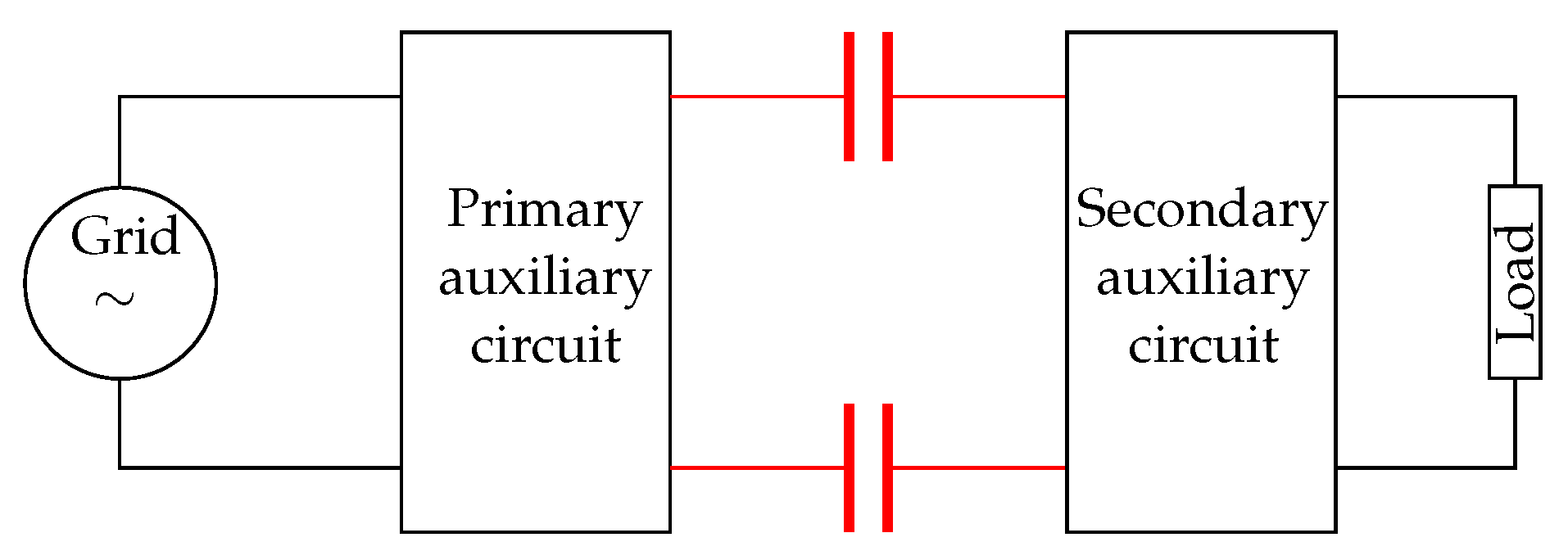
Figure 3.
Capacitive power transfer scheme.

Figure 4.
Capacitive wireless coupling: (a) Physical four-plate structure (b) Equivalent model with main, leakage and cross-coupling capacitances (c) Equivalent pi-model.
Figure 4.
Capacitive wireless coupling: (a) Physical four-plate structure (b) Equivalent model with main, leakage and cross-coupling capacitances (c) Equivalent pi-model.

Figure 5.
Representation of the capacitive coupling model.

Figure 6.
Two-port network.

Figure 7.
Six-plate structure capacitive coupling model and current-depended source model representation.
Figure 7.
Six-plate structure capacitive coupling model and current-depended source model representation.

Figure 8.
Two-plate structure.

Figure 9.
Four-plate CPT structures.

Figure 10.
Matrix structure.

Figure 11.
Concentric structures.

Figure 12.
Electric field repeater.

Figure 13.
L compensation circuit topologies, with and the resistive losses within the network.

Figure 14.
Double side compensation circuit.

Figure 15.
L-section stages for multistage networks.

Figure 16.
Some examples of other compensation topologies: (a) Composite LCL (b) Modified LLC (c) Transformers.
Figure 16.
Some examples of other compensation topologies: (a) Composite LCL (b) Modified LLC (c) Transformers.

Figure 17.
Overview of compensation circuits.

Figure 18.
PWM based converter.

Figure 19.
Class E inverter.

Figure 20.
General full-bridge inverter network.


Table 1.
Comparison of the main properties of GPT, IPT CPT.
| GPT | IPT | CPT | |
|---|---|---|---|
| Distance | mm—km | mm—5 m [26] | mm—tens of cm |
| Maximum power transfer | GW | 50 kW [27] | 2.4 kW [28] |
| Efficiency | ∼100% | ∼95% | ∼95% |
| Frequency range | DC Hz—GHz | kHz—MHz | kHz—MHz |
| Advantages | •Suitable for any power level •Suitable for a full frequency range •Almost no power losses | •Improved user experience •Robustness & durability •Facilitating miniaturization •Increasing safety •Improved mobility •Design capabilities | •Same advantages as IPT •Power transfer through isolated metal object •Minimal Eddy current losses •Less expensive design than IPT •Less voluminous than IPT •Lower EMI than IPT •Simple configuration for charging multiple receivers |
| Disadvantages | •Disorder •Less design freedom •Less uniform •Less mobile •Maintenance | •Not abundant •Implementation cost •Less efficient •EMI at high power transfer •Efficiency drop with | •Low capacitive coupling •Short distances •High requirements on components •Safety |
Table 2.
Improvements on CPT over the last years.
| Reference/Year | Improvement | Distance [mm] | Frequency [MHz] | Output Power [W] | Efficiency [%] |
|---|---|---|---|---|---|
| [33]/2008 | New CPT system | 0.22 | 40.5 | 44.3 | |
| [48]/2011 | Matrix plate structure | 0.5 | 0.616 | 2.5 | 51 |
| [28]/2015 | Compensation network | 150 | 1 | 2400 | 90 |
| [49]/2016 | Compensation network | 360 | 1.5 | 105 | 67 |
| [45]/2016 | Compensation network | 10 | 1 | 1.87 | 85.9 |
| [50]/2018 | Six-plate structure | 150 | 1 | 2000 | 91 |
| [39]/2018 | Two-plate structure | 110 | 6.78 | 350 | 74.1 |
| [18]/2018 | CPT in fresh water | 20 | 107.7 | 360 | 90 |
| [51]/2019 | Bidirectional CPT system | 150 | 0.625 | 80 | 80 |
| [30]/2020 | Bidirectional CPT system | 0.25 | 13.56 | 20.5 | 78.8 |
Publisher’s Note: MDPI stays neutral with regard to jurisdictional claims in published maps and institutional affiliations. |
© 2021 by the authors. Licensee MDPI, Basel, Switzerland. This article is an open access article distributed under the terms and conditions of the Creative Commons Attribution (CC BY) license (https://creativecommons.org/licenses/by/4.0/).
Share and Cite
MDPI and ACS Style
Lecluyse, C.; Minnaert, B.; Kleemann, M. A Review of the Current State of Technology of Capacitive Wireless Power Transfer. Energies 2021, 14, 5862. https://0-doi-org.brum.beds.ac.uk/10.3390/en14185862
AMA Style
Lecluyse C, Minnaert B, Kleemann M. A Review of the Current State of Technology of Capacitive Wireless Power Transfer. Energies. 2021; 14(18):5862. https://0-doi-org.brum.beds.ac.uk/10.3390/en14185862
Chicago/Turabian StyleLecluyse, Cédric, Ben Minnaert, and Michael Kleemann. 2021. "A Review of the Current State of Technology of Capacitive Wireless Power Transfer" Energies 14, no. 18: 5862. https://0-doi-org.brum.beds.ac.uk/10.3390/en14185862
Note that from the first issue of 2016, this journal uses article numbers instead of page numbers. See further details here.