
Setting and Testing of the Out-of-Step Protection at Mongolian Transmission System


1
Department of Electrical Engineering, Information Technology and Cybernetics, University of South-Eastern Norway, 3918 Porsgrunn, Norway
2
Power System Analysis and Research Department, National Dispatching Centre State-Owned LLC, Ulaanbaatar 14210, Mongolia
3
Facultad de Ingeniería Mecánica y Eléctrica, Universidad Autonoma de Nuevo Leon, Monterrey, Barragán No. 4904 Norte, Col. Hogares Ferrocarrileros, Monterrey C.P. 64260, Nuevo León, Mexico
*
Author to whom correspondence should be addressed.
Energies 2021, 14(23), 8170; https://0-doi-org.brum.beds.ac.uk/10.3390/en14238170
Submission received: 11 July 2021
/
Revised: 12 October 2021
/
Accepted: 14 October 2021
/
Published: 6 December 2021
Abstract
:Modern distance relays have integrated numerous protection functions, including power-swing blocking and out-of-step or pole-slip tripping functions. The main purpose of the power-swing blocking function is to differentiate faults from power swings and block distance or other relay elements from operating during stable or unstable power swings. Most power-swing blocking elements are based on traditional methods that monitor the positive sequence impedance rate. The required settings for the power-swing blocking elements could be difficult to calculate in many applications, particularly those where fast swings can be expected. For these cases, extensive stability studies are necessary to determine the fastest rate of possible power swings. This paper presents a detailed step-by-step method for settings calculation of out-of-step (OOS) protection, both blocking and tripping functions considering a generic two-source system. Then the method is applied to define the protection relay settings installed at the interconnection between the Russian and Mongolian power systems, as it is crucial to feed the demand-rich Mongolian power system. In this paper, a specific impedance method is used for defining the OOS protection settings. This paper innovates by testing the settings using the recordings of the major events of 15 September 2018 in two approaches: hybrid co-simulation and cyber-physical. Both tests have demonstrated the appropriate performance of the proposed settings and proving the proposed methodology works appropriately.
1. Introduction
Power systems operating in pseudo-steady-state conditions run typically close to their nominal frequency, and all the electrical variables are inside the operational limits [1,2]. However, some operating conditions can push the electromechanical variables outside acceptable limits and endanger the secure and economic operation of the electrical power system [3]. When the power system is subject to a severe disturbance, the system is not able to reach a new operating equilibrium point. This is known as an unstable condition [4,5].
Power system faults, line switching, generator disconnection, and the loss or application of large blocks of load result in sudden changes to electrical power, whereas the mechanical power input to generators remains relatively constant [6]. These system disturbances cause oscillations in synchronous machine rotor angles, and those oscillations can result in severe power flow swings [7]. Depending on the severity of the disturbance and the actions of power system controls, the system may remain stable and return to a new equilibrium state, experiencing what is referred to as a stable power swing. On the other hand, severe system disturbances could cause significant separation of generator rotor angles, large swings of power flows, large fluctuations of voltages and currents, and eventual loss of synchronism between groups of generators or between neighbouring utility systems [8,9].
Large power swings, stable or unstable, can cause unwanted protection relay operations at different network locations, which can aggravate further the power-system disturbance and cause power blackouts [10].
A power-swing blocking (PSB) function is available in modern distance protection relays to prevent unwanted distance relay element operation during power swings [11]. The main purpose of the PSB function is to differentiate between faults and power swings and block distance during a power swing. However, faults that occur during a power swing must be detected and cleared with a high degree of selectivity and dependability. In such situations, the PSB function should unblock and allow the distance relay elements to work and clear any faults that occur in their zone of protection during a power swing condition [12].
Most PSB elements are based on traditional methods that monitor the rate of change of the positive-sequence impedance (dZ1/dt). The required settings for the PSB elements could be difficult to calculate in many applications, particularly those where fast swings can be expected. For these cases, extensive stability studies are necessary to determine the fastest rate of possible power swings.
Large power system disturbances can lead to loss of synchronism among interconnected power systems [13]. If such a loss of synchronism occurs, it is imperative that the system areas operating asynchronously separate immediately to avoid wide-area blackouts and equipment damage [14]. An out-of-step tripping (OOS) function is available in modern distance relays to differentiate between stable and unstable power swings. During unstable power swings, the OOS function initiates the controlled tripping of appropriate breakers at predetermined network locations to separate networks quickly and in a controlled manner in order to maintain the power system stability and service continuity; it is called controlled-islanding [15]. For the conditions mentioned above, the OOS protection scheme is considered System Integrity protection scheme (SIPS); it is the protection scheme designed to detect potentially hazardous conditions and then to prevent a complete blackout of endangered parts of a power system.
Distance relay elements prone to operate during unstable power swings should be inhibited from operating to prevent system separations from occurring at random and in other than preselected locations. Traditionally, OOS functions monitor the rate of change of the positive-sequence impedance. Unfortunately, the required settings for the OOS function are difficult to calculate, and in most applications, an extensive number of power system stability studies with different operating conditions must be performed. This is a costly exercise, and one can never be sure that all possible scenarios and operating conditions were considered.
OOS protection is still a very productive research area; although the working principle is still the same, an impressive number of scientific publications address the issue of detection and coordination of the OOS protection scheme. The classical detection method is impedance-based, and it is the most popular method followed by the most recent methods, such as R-Rdot [16,17], the swing-centre voltage (SCV)-based technique, the wide-area synchrophasor-based technique [18,19], an equal-area criterion-based technique [20], heuristic algorithms [21], and decision trees [22]. In addition, a neural network-based detection method is proposed in [23], and [24] proposed the application of fuzzy logic using an adaptive network-based fuzzy interface (ANFIS).
This paper presents a detailed step-by-step method for settings calculation of OOS protection, including both blocking and tripping functions, considering a generic two-source system. is The method is then applied to define the protection relay settings installed at the interconnection between the Russian and Mongolian power systems. In this paper, the impedance method is used for defining the OOS protection settings.
The transmission lines interconnecting Russia and Mongolia power systems are significant for the secure and reliable operation of the Mongolian power system; any malfunction of the protection relays will cause a complete blackout in the Mongolian power system, as happened in 2017 and 2018. Consequently, it is imperative to ensure the correct settings of those protection relays to ensure an appropriate level of reliability. It has been recognised that the impedance-based techniques require extensive offline stability studies for obtaining the settings. However, in this paper, the focus is on defining the settings of transmission line 203 (a vital part of the Russia-Mongolia interconnection); as a consequence, this scientific paper will address this challenge by specific case defined methodology (see details of the application scope and limits at Section 4).
The distance relay settings installed at the Russia-Mongolia Interconnection (specifically Line 203 with Schweitzer Engineering Laboratories, SEL-421) has been calculated using the methodology presented in this paper (see Section 5 and Section 6). The validation process of those settings starts by using the results of time-domain simulations obtained from DIgSILENT PowerFactory, considering the full detailed model of the Mongolian Power system. The simulation results demonstrated the appropriate performance of the relay settings and show that the protections are able to detect an unstable power swing and block for a secure power swing (see Section 6). Finally, the correctness of settings and the detection and isolation of unstable power swings by the real protection relay (SEL-421) is tested using a cyber-physical approach. The physical relay is set and monitored using the software AcSELerator; a secondary current injection approach is used to provide the appropriate low power voltage and current signals to the relay using an OMICRON CMC356. The CMC356 is fed with the data recorded by a phasor measurement unit (PMU) installed in the Mongolian power system. The recorded data is based on three-phase voltages and currents measured during an important power swing that took place on the network of Mongolia on 15 September 2018 and lasted for about 10 s. The cyber-physical test has demonstrated without any possible doubt that the proposed setting will appropriately be able to detect and perform accordingly during a power swing event (see Section 6). This paper presents the general conclusion and remarks in the last section.
The main contribution of this paper is providing the transmission system operator of Mongolia with the appropriate set of settings for the OOS protection function at the SEL-421 installed at the critical Line 203; those settings have been successfully updated in the protection relays located in the Russia-Mongolia interconnection, and on the recent major event of August 2021 the proposed setting acted and avoided the total blackout of the Mongolian power system. This paper presents a comprehensive explanation of the power swing phenomenon and uses the locus of the measured impedance on the explanations (Section 2). In this paper, a practical contribution for the power utility and protection engineers is that the protection settings are not tested using simple simulations; this scientific paper has innovated by testing the settings using the real-life recordings of the major events of 15 September 2018 (see Section 3) that happened in the Mongolian power system. This scientific paper contributed to the knowledge by using two testing approaches: hybrid co-simulation (novel technique but necessary for OOS, Section 6) and cyber-physical (the most common approach used in the field, Section 6). This scientific paper contributed to the scientific and the engineering community by showing a straightforward methodology for calculating the OOS settings and illustrating them with numerical step-by-step calculations). Both tests have demonstrated the appropriate performance of the proposed settings and proved that the proposed methodology works appropriately.
2. Power Swing and Out of Step Context
2.1. Power Swing Phenomena
The phenomenon of power swing is used to define the power flow variations that occur when the synchronous generator rotor angles are advancing or retarding relative to each other in response to a system disturbance [1] (e.g., power imbalances and changes in the power flow direction, line switching, loss of generation, faults, etc.).
Large disturbances (e.g., short circuit) may cause loss of synchronism between a generator and the rest of the power system or between neighbouring utility interconnected power systems. The loss of synchronism or pole slip is an extremely dangerous situation; it is a condition whereby a generator, or group of generators, terminal voltage angles (or phases) go past 180° with respect to the rest of the connected power system. In this condition, the synchronous generators experience high electrical currents and electromechanical force at the generator windings, and there is an exposure to high levels of transient shaft mechanical torques.
The power swing can be classified based on the final rotor angle stability of the power system. When the power swing is such that the power system is able to regain a stable operating condition or reach an equilibrium point, such a situation is known as stable power swing. On the other hand, an unstable power swing refers to a power swing that will result in a generator or group of generators experiencing pole slipping, for which some corrective action must be taken.
During an unstable power swing, the integrity of the power system must be preserved; therefore, it is vital that before the loss of synchronism occurs, the synchronous generator or system areas operating asynchronously must be separated immediately to avoid widespread outages and equipment damage [7].
The so-called intentional controlled islanding of the power system is the most effective mitigating way to minimise the effect of the unstable power swing.
The controlled islanding is typically implemented by the appropriate setting of the out-of-step protection systems. The intentionally controlled islanding is achieved with the out-of-step tripping (OST) protection system at pre-chosen network locations.
The primary purpose of the OST protection system is to detect power swings and differentiate stable from unstable ones effectively, and then initiate system area separation at the pre-defined network locations. To do so, the OST function uses the appropriate source-voltage phase-angle difference between systems to maintain the power system stability and service continuity.
The OST systems must be complemented with out-of-step blocking (OSB) of distance relay elements or other relay elements prone to operate during unstable power swings. OSB prevents system separation from occurring at any locations other than the preselected ones. More discussion about the OST protection system and the OSB functionality are included in the next section.
2.2. Effect of the Out of Step Condition on Transmission Line Protection Relay
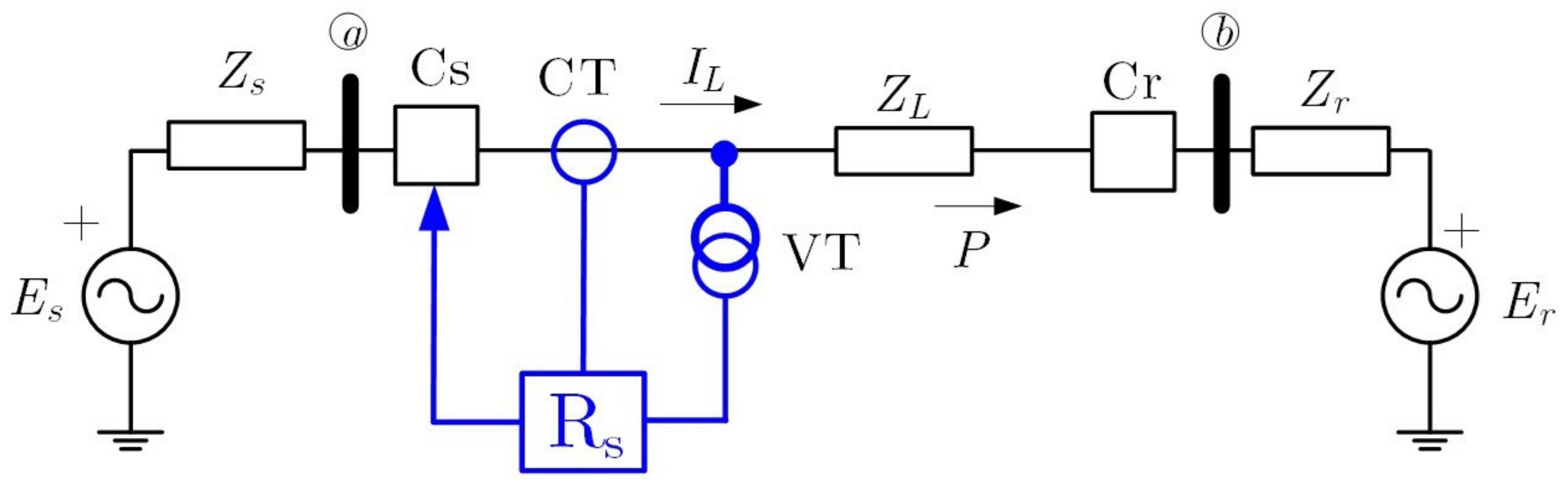
A very simple and didactic way to explain the effect of the out of step condition in the transmission protection relay is considering a straightforward power system; it consists of two equivalent generators (or equivalent sources) interconnected throughout a simple lossless transmission line connecting two equivalent generators (see Figure 1).
During and after a large disturbance (e.g., fault, change of topology, etc.), the power system must change the operational conditions (state) from one stable equilibrium point to another (if the system is stable). During the process, the power system is subject to power swings. Transmission lines interconnecting large power systems (or areas) are susceptible to power swings, especially if those along transmission lines are hardly loaded.
Considering the power system is rotor angle transiently unstable, this condition will cause the large separation of the equivalent generators rotor angles, large swings of power flows, large fluctuations of voltages and currents, and eventually lead to a loss of synchronism between the generators or between neighbouring utility systems. It is important to note that the two equivalent generators are in phase, the voltages are at their maximum, and the currents are at a minimum. Conversely, when the two equivalent generators are 180° degrees out-of-phase, the voltages are at their minimum, and the currents are at their maximum.
The best way to visualise and detect OOS phenomena as observed by the line protection relay is to analyse apparent impedance variations with time as viewed at the terminals of one of the equivalent generators. During the power swing, the apparent swing loci depend on the type of governor and excitation system installed at the generation unit, along with the type of disturbance that initiated the swing.
The impedance that a distance relay measures during the OOS condition can be easily obtained for the simple two-equivalent generators shown in Figure 1. The current flowing in the transmission line (IL) is calculated as:
During the power swing event of the OOS condition, the direction of the electrical current at the transmission line (IL) will remain the same during the whole event, but the magnitude will change, caused by the voltage changes with respect to each other. The apparent positive impedance (Z1) measured by the secondary instrument transformers (VT and CT) and the distance protection relay installed at the sending bus “s” can be obtained as:
Consider the voltage Es has a phase angle of δ leading respect to the voltage Er, and the ratio between the two voltage magnitudes is constant (k):
It is simple to derivate an alternative expression for |Es|/(Es − Er) considering the angle changes (δ) and the constant factor k:
In this particular discussion, the two voltages sources can be assumed to have the same magnitude (|Es| = |Er|), as a consequence, the constant k becomes unity, and the above-presented equation is simplified as:
Now the impedance measured by the distance relay (ZRs) can be rewritten as:
For the general case of |Es| ≠ |Er|, the impedance measured by the distance relay (ZRs) results:
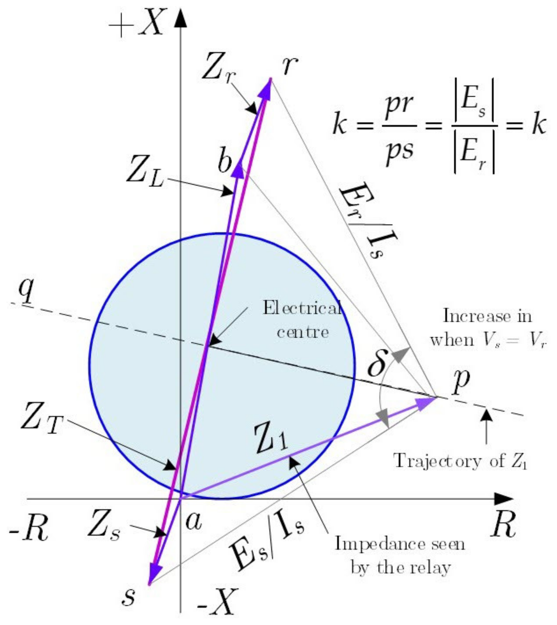
The angle δ is the most important variable defining the power swing during the OOS situation and the effects of the apparent impedance as measured by the distance protection relay, the angle represents the phase angle between the two sources (Es and Er). The Equation (6) can be easily represented in Figure 2 by taking into account the geometrical representation of it.
The locus of the measured impedance and the distance relay (Rs) during a power swing event is shown in Figure 2 as a straight line that intersects the segment r to s at its middle point. The intercepting is commonly named the electrical centre of the swing. On the other hand, it is straightforward to see that the angle between the two straight line segments that connect p to points a and b is equal to the angle δ. For the particular case of the angle δ reaches the value of δ = 180°, the impedance (Z) is precisely at the position of the electrical centre. Figure 1 shows that the impedance trajectory measured by the distance relay during a power swing is that trajectory will cross any relay characteristic that covers the line (impedance, mho, quadrilateral, etc.), as the provided electrical centre will fall inside the line [25].
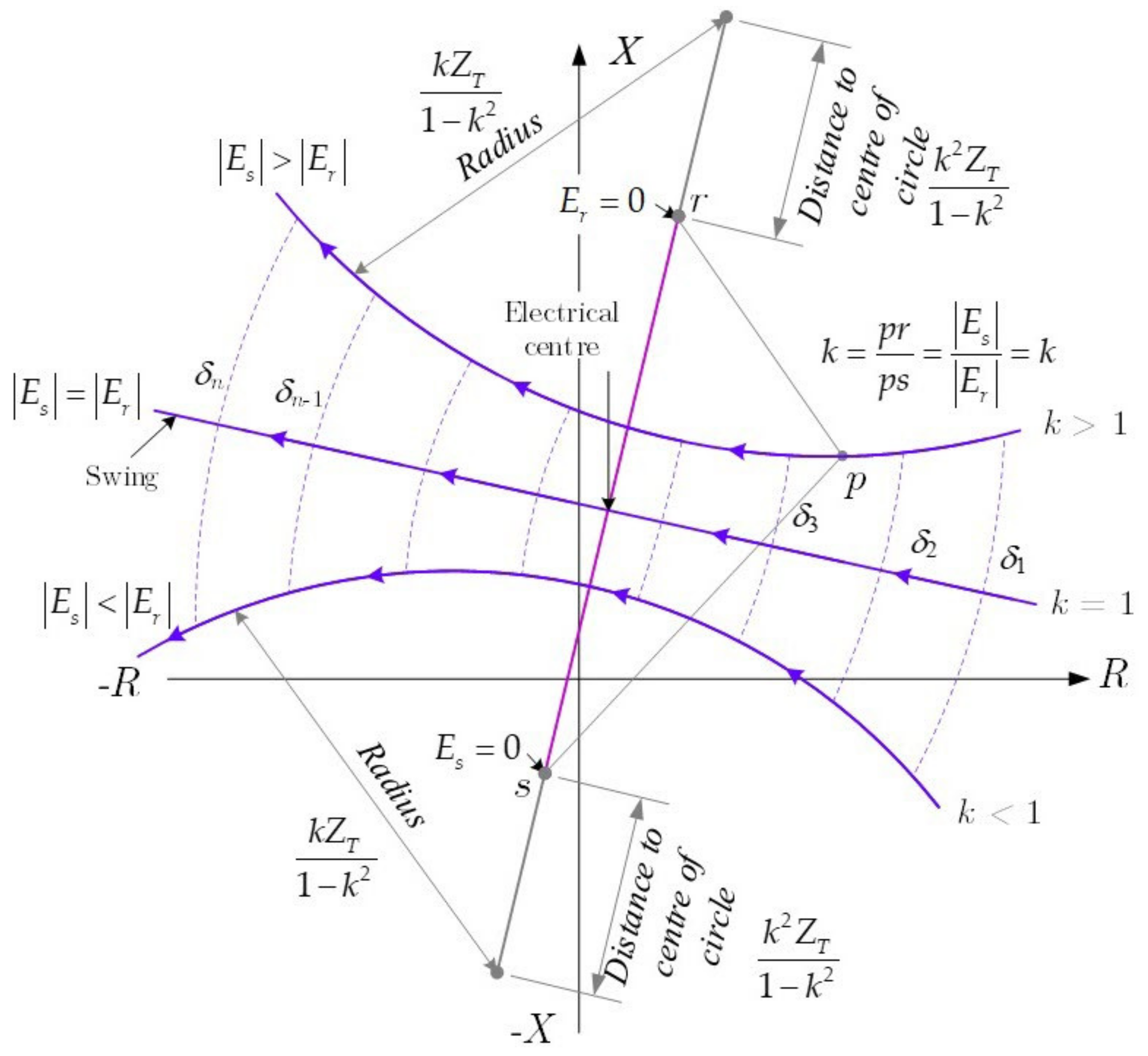
Now, consider that the ratio of the source’s voltages magnitudes is different to one k ≠ 1 (|Es| ≠ |Er|), it can be demonstrated that the impedance loci will correspond to circles (a demonstration of this can be found at EW Kimbark’ book [26] (Chapter X)).
When the voltage source ratio k = |Es|/|Er| = 1, the impedance locus trajectory is presented by a straight line signalled as pq in Figure 3; the pq line is the perpendicular bisector of the total system impedance represented by the straight-line segment between a and b. As shown in Figure 1, the angle formed by the intersection of pa and pb on pq is the separation angle δ between two equivalent sources. As the voltage Es advances ahead of voltage Er, the impedance locus moves from p toward q and δ increases. When the locus intersects the total impedance line ab, the systems are 180° of phase. For conditions where the voltage source ratio k = |Es|/|Er| k > 1, the electrical centre will be above the impedance centre of the system (pq). When k = |Es|/|Er| is less than one (k < 1), the electrical centre will be below the impedance centre of the system.
During the power system’s operation, the system’s electrical centres vary as the system impedances behind the line terminals and the equivalent internal generator voltages vary. The rate of slip between systems depends on the accelerating torques and system inertias. Transient stability studies provide the best means to determine the slip rate and locations where the power swing loci will go relative to the generator terminals or high-side terminals of the generator step-up transformer. Knowing the loci locations helps to determine the best relay scheme to detect an out-of-step condition.
Phase distance protection relays (Rs) measure the positive-sequence impedance for three-phase and two-phase faults. The positive sequence impedance measured by the relay Rs was calculated in (6), and it easy to see that during an OOS condition, the positive sequence impedance varies as a function of the phase angle δ, as the angle of separation between the two equivalent system source voltages varies, the positive sequence defined in (6) will change.
During a power swing, stable or not, the distance relay elements will operate. If the measured impedance trajectory during a power swing enters the distance projection relay characteristic, the relay will operate.
Typically, the Zone 1 distance relay elements do not include any intentional delay (it is considered an instantaneous action); consequently, the distance relay elements are prone to operate during a power swing. The Zone 2 distance relay elements used in pilot relaying systems are very prone to operate during a power swing, e.g., blocking or permissive type relay systems. On the other hand, the backup zone step distance relay elements typically are not prone to operate during a power swing, as the backup zone includes an intentional time delay. However, depending on its setting and the time it takes for the swing impedance locus to traverse through the relay characteristic, as a consequence, the backup zone step distance relay elements will not operate during the power swing.
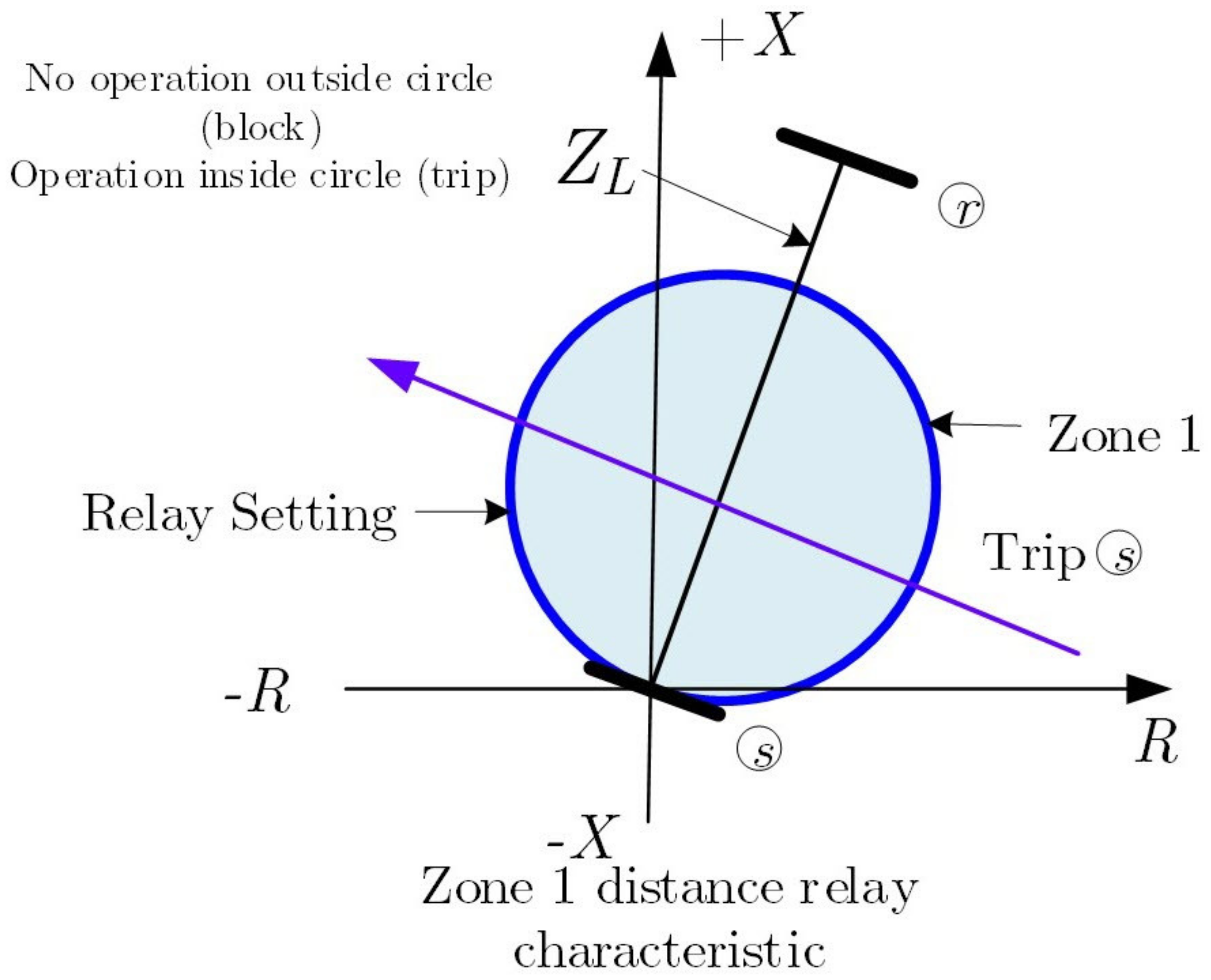
The typical operating characteristic of an mho distance relay is shown in Figure 4; the locus of the impedances measured by the distance production relay during a power swing (k = 1 is assumed) is highlighted.
The directional comparison blocking scheme characteristic of the distance relay is shown in Figure 5. It shows a simple comparison of the blocking scheme characteristic of the distance relay and how it may be impacted by the swing locus.
The relative magnitude of the protected line (|ZL|) and the equivalent system source impedances (|Zs|, |Zr|) is an essential factor that defines the performance of distance protection relays during a power swing in the power system. Suppose the line positive-sequence impedance of the transmission line is large compared with the equivalent source’s impedances. In that case, the distance relay elements of the protection relay may operate during unstable swings and operate during swings from which the power system may recover and remain stable.
2.3. Out-of-Step Protection Philosophy
Traditional protective relays are prone to respond to stable or unstable power swings; this behaviour causes unwanted tripping of transmission lines and/or any other power system elements. It includes the unwanted trip caused by several other protection elements: non-directional overcurrent, directional overcurrent, undervoltage, distance, and directional comparison systems.
The objective of OOS protection is very simple: the protection philosophy is to avoid tripping of any power system element during stable swings. This protection system is intended to protect the power system during unstable or OOS conditions.
Intentional area separation is a mechanism used to separate interconnected lines during a loss of synchronism condition. This intentional separation must be performed very quickly in an automated fashion in order to avoid the potential damage of equipment and of disconnecting service to a significant area of the power system. The out-of-step protection functions must be able to detect stable power swings and out-of-step conditions by using the fact that the voltage/current (apparent positive sequence impedance) variation during a power swing is gradual while it is virtually a step-change during a fault.
Faults and power swings can cause the measured apparent positive sequence trajectory to go into the operating characteristic of a distance relay element. As the phenomenon of short circuit and the power swings have a very different time constant, the rate of change of the positive-sequence impedance can be used to differentiate between a short circuit and power swing or OOS condition. The short circuit shows a very high rate of change of the positive-sequence impedance when compared with the power swing or OOS condition, and the OOS condition also depends on the slip frequency of the OOS.
It is clear that the impedance measurement by itself cannot be used to distinguish an OOS condition from a phase fault. Instead, tracking the rate of change of measured apparent impedance is the fundamental method for discriminating between faults and power swings. One mechanism used to detect the OOS and block the operation of the distance protection element is considering the difference in the rate of change of the impedance; this mechanism is typically used to block the distance protection element trip before the measures impedances trajectory enters into the operating characteristic of the distance protection elements.
The out-of-step protection function uses two functions: (1) the out-of-step tripping protection function, and (2) the out-of-step blocking protection function.
The out-of-step tripping (OOST) protection function is dedicated to discriminating between stable and unstable power swings, and then initiating area separation during a condition of loss of synchronism.
The out-of-step blocking protection (OOSB) function discriminates between faults and stable or unstable power swings.
3. Mongolian Power System and Major Event of September 2018
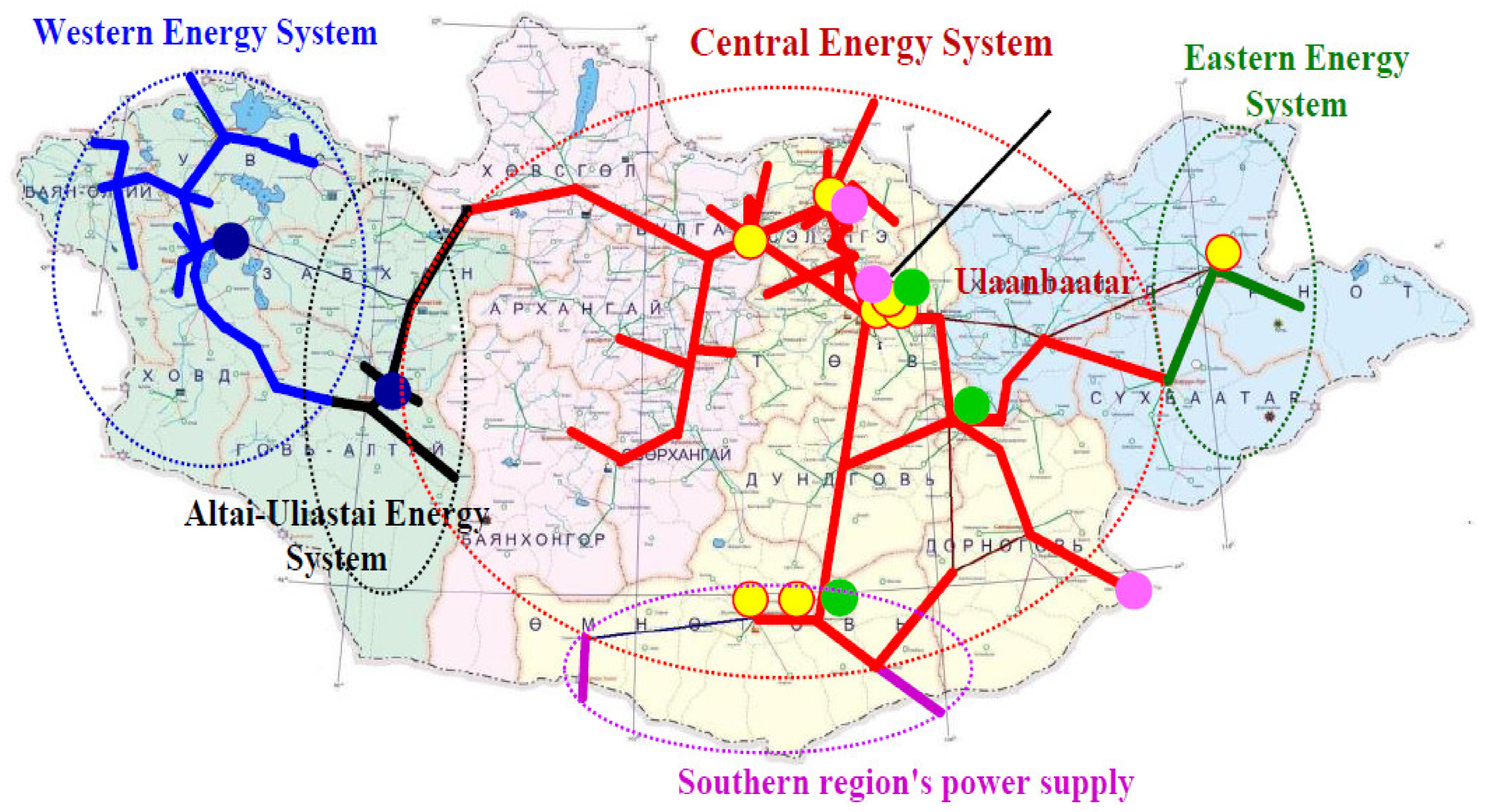
The electricity sector in Mongolia has been unbundled into generation, distribution, transmission, and dispatch companies. The electricity supply is provided through five regional energy systems (see Figure 6): Central energy system (CES), Western energy system (WES), Altai Uliastai energy system (AUES), Eastern energy system (EES) and Southern energy system (SES) of the country.
There are nine thermal power plants, three wind power plants, six solar plants, and two hydro plants in the whole power system. Power generated by all generation sources is transmitted through 220/110 kV overhead transmission lines (OHTLs). Coal-fired power plants generate approximately 85 per cent of the total electricity generated in Mongolia. On the other hand, renewable energy sources (RES), including hydro, wind, and solar, generate 20 per cent of total electricity. In recent years, many projects to construct renewable energy power plants have been advanced. However, the progress has generally been slower than expected.
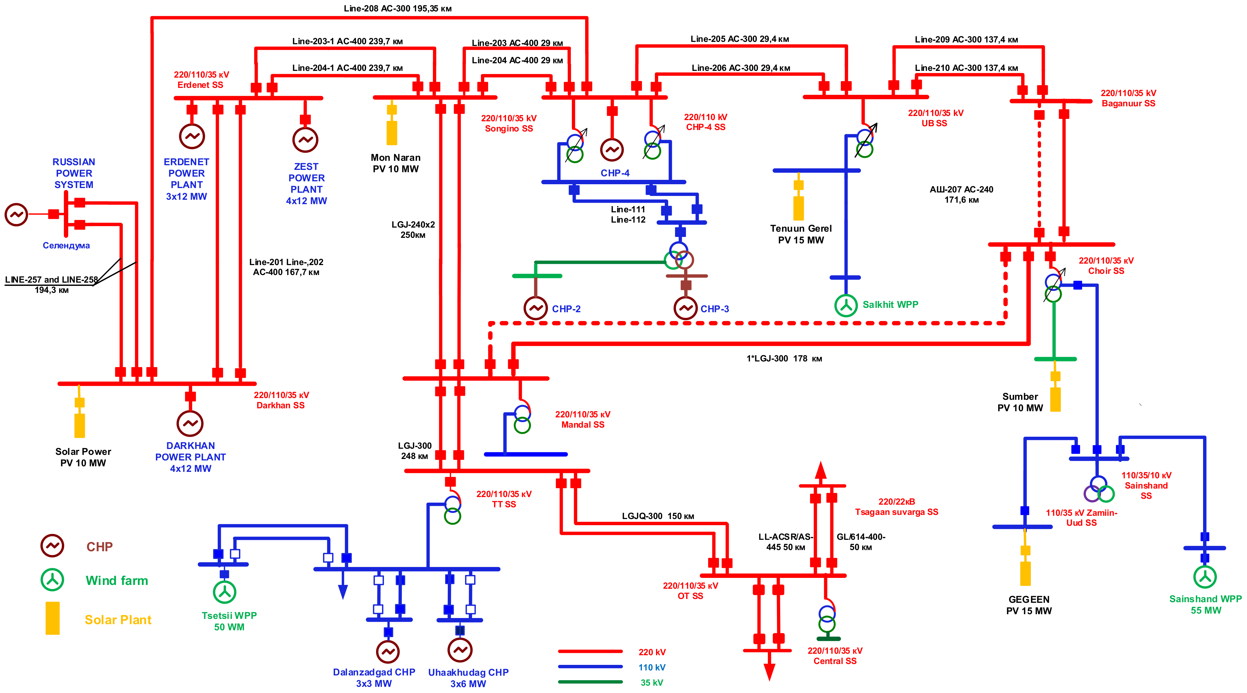
In Mongolia, aimag is the word used to describe the first-level administrative subdivision. The country currently has 21 aimags. The capital city of Mongolia is Ulan Bator and it is administrated as an independent municipality. As shown in Figure 6, the electricity is supplied through five regional energy systems. CES is the largest energy system in Mongolia. The total installed capacity of the CES is 1281 MW [27]. CHPs occupies 83.5% and RES plants occupy 16.5% of the total installed capacity, and the shortage is covered by electricity imported from Russia, which amounts to about 20%. Several loads that have been recently added to the Mongolian power system are increasing the electricity requirements, such as the developments at the Tavantolgoi coal mine and the Oyutolgoi copper mine in the South Gobi region. Oyutolgoi is one of the most significant developments in Mongolia with regard to the exploitation of copper and gold mining. In 2019, Oyutolgoi’s peak power demand was estimated at just under 200 MW, and the average load is 149 MW [28]. WES covers three aimags in the western part of Mongolia with a total demand of 20 MW [28]. EES covers two aimags in the eastern part of Mongolia with a total demand of 36 MW [28]. CES has been strategically interconnected with ESS, the Altai-Uliastai Energy system, and the Russian electricity network. The interconnection between the EES and the Altai-Uliastai energy system is carried out by using overhead transmission lines at a level of 110 kV. As mentioned before, the interconnection between the Mongolian power system and the Russian power system has strategic importance, especially regarding control and security of the Mongolian power system; this interconnection provides frequency control and regulation to the Mongolian power system, and it is a key element to cope with the local generation deficits during the f cold Mongolian winters. For the interconnection a double circuit transmission line between CES and Russia is at 220 kV. WES is also connected to the Russian electricity network (see Figure 7).
The Mongolian power system has very particular properties, including a remarkable difference between the peak load (during the evening, ~19:00 h) and the low nighttime load (off-peak hours, 01:00 h); these differences directly depend on the type of consumers. The cold Mongolian winters put an extra burden on the electrical power system as the winter season provides the maximum peak demands on the system, and daily electricity demand is about 18.0–23.0 million kWh, while the daily difference between peak and low load reaches 280–350 MW.
The Mongolia power network comprises two high voltages levels, 110 and 220 kV. Given that the area of Mongolia is approximately ~542% larger than that of Great Britain (UK), and that it has a very remote load, the transmission lines range from 1044 km at 220 kV and 2932 at 110 kV. Ulan Bator is the most densely populated area of the whole country (population of 1,615,094, 704 people per square mile), and it is covered by a distribution network (0.4–35 kV substations) of over 5824 km in the CES area.
On 15 September 2018, at 09:30:14:59, more than two million customers were affected when a power outage struck the Central Energy System of the Mongolian power system. About 900 MW of power was curtailed during this disturbance. The single line to ground fault occurred at the 220 kV side of CHP-4, which is the biggest thermal power plant in CES. Even though the busbar protection of the 220 kV side was successfully cleared of the fault within 90 ms, however, the main 220 kV lines and generators were disconnected at CHP-4 by bus protection. Immediately after these events, the system’s 220 kV voltage continued decreasing; after a delay of around 3.0 s, the 220 kV voltage of the bus reached 179.9 kV (V = 0.81 pu) due to a shortage of the reactive power source. CES was operating its system with voltages below critical levels and with inadequate reactive reserve margins.
Several unplanned outages occurred on 15 September 2018 that were at CHP-4 generating G-2, and G-3 tripped offline due to over excitation meanwhile the generators were making terminal voltage adjustments. These generators that tripped later began the blackout sequence in the CES (Central Energy System). As a result of the increased import power from the Russian grid, at CES the single circuit 203 220 kV line quickly became overloaded with power oscillations. That line was then tripped by out of step protection. Fault recording analysis investigators determined that the low voltage and low reactive power margins in the CES on 15 September 2018 prior to the blackout could have led to a voltage collapse.
4. Settings Calculations: A Step-by-Step Process
The out-of-step relaying philosophy looks very simple on paper; however, the real implementation in very large real power systems can be challenging, especially because of the large number of operating conditions to be assessed [25].
The objective of this paper is to present a detailed step-by-step method for settings calculation of out-of-step protection, both blocking and tripping functions, with a focus on the settings of the protection relay installed at the interconnection between the Russian and Mongolian power systems. Consequently, the proposed step-by-step method for setting the out-of-step protection scheme is a bit different from the traditional method published in some scientific documents as the technical report TR-79—Application of Out-of-Step Protection Schemes for Generators from the IEEE [25] and the [9].
The Russia-Mongolia interconnection is the primary concern of this paper; the OOS protection scheme is already in place in the 220 kV transmission lines related to the main power plan in Mongolia (CHP-4) and the Russian power system. Consequently, it is not necessary to determine the locations of the out-of-step tripping protection function and the system separation during an OOS condition. Ideally assessing the optimal location of the out-of-step tripping protection function can be a complex process where mathematical optimisation is used together with time-domain simulation to obtain the swing loci during various system conditions. However, in reality, the transmission system operator uses its experience from previous major events and real physical constraints to narrow down the possible locations of the OOS tripping protection.
The settings of the OOS protection scheme require defining the most critical operation conditions that can derive into stability problems; this process can be time-consuming and complex, but again, the experience of the transmission system operator plays an essential role as several operational conditions can push the power system to the. In the case of the Mongolian power system, many of the previous major incidents related to the interconnection to the Russian power system and the CHP-04 are found to cause stability problems, which cause a cascade event that produces a full blackout. In this scientific paper, the experience of the system operator dictates the interest in power swings related to events in the 220 kV corridor connecting Russia and Mongolia.
This section focuses on the features of OOS logic for the OOS blocking and OOS tripping functions. OOSB (out-of-step blocking) logic blocks phase distance elements and Zone 1 ground distance elements during power swings, and OOST (out-of-step tripping) logic trips the circuit breaker during unstable swings.
4.1. Out-of-Step Blocking Logic
The OOSB logic is used to discriminate between power swings and faults to prevent unwanted distance element trips [25]. One mechanism typically used to detect the OOS condition is to measure the difference in the rate of change of the impedance. Then logic blocks the operation of distance protection elements before the impedance enters the protective relay operating characteristics. The actual implementation of the measurements of the impedance rate of change is easily obtained by using two impedance measurement elements together with a timing device. If the measured value of the impedance stays between the two impedance measurement elements for a predetermined time (threshold), the logic will declare the condition as an OOS, and an OOSB logic issues a signal that blocks the distance relay element operation.
This protection logic assumes that it has set the phase-to-phase mho distance element Zone 2 reach.
First, calculate the impedance reach settings for the outer and inner zone used to differentiate between power swings and faults; once these settings are available, then calculate OOSBD (out-of-step block time delay) [2].
OOSB logic blocks phase distance protection during a swing when the measured positive-sequence impedance enters the operating characteristics of the phase distance elements [2]. However, in practice, it is not necessary to block all zones.
In this paper, the OOSB logic is used to block instantaneous Zone 1 and Zone 2. The phase distance elements (ANSI number 21 and include in SEL relays as 21P) are based on a traditional mho phase distance element. The reach of the Zone 1 Phase Distance Element is assumed to provide instantaneous protection (non-intentional delay) for phase-to-phase, phase-to-phase-to-ground, and three-phase faults in the first 80 per cent of the transmission line:
The reach of the Zone 2 phase distance element is defined considering the following criterion: It must have adequate reach to detect all phase-to-phase, phase-to-phase-to-ground, and three-phase faults along the protected line to make some delayed tripping occur for faults located in the last 20 per cent of the line.
The OSB logic typically supervises forward-looking Zones 1 and 2 because the operation time of these two zones is ordinarily shorter than the time period during which the impedance of a power swing resides in these protection zones [2]. Also, during a power swing, the relay typically does not block the overreaching zones of protection that provide time-delayed tripping, so Zone 3 is not considered.
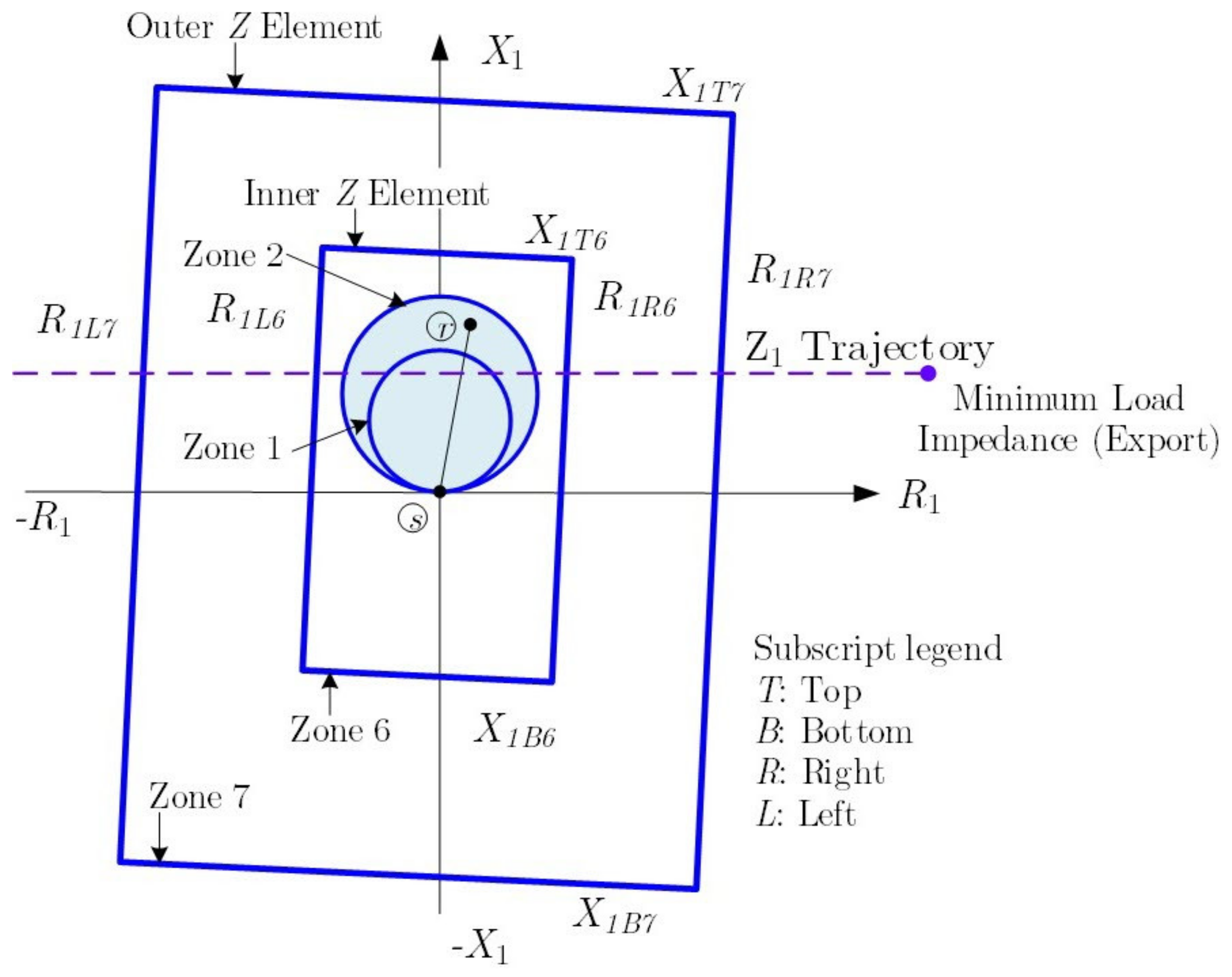
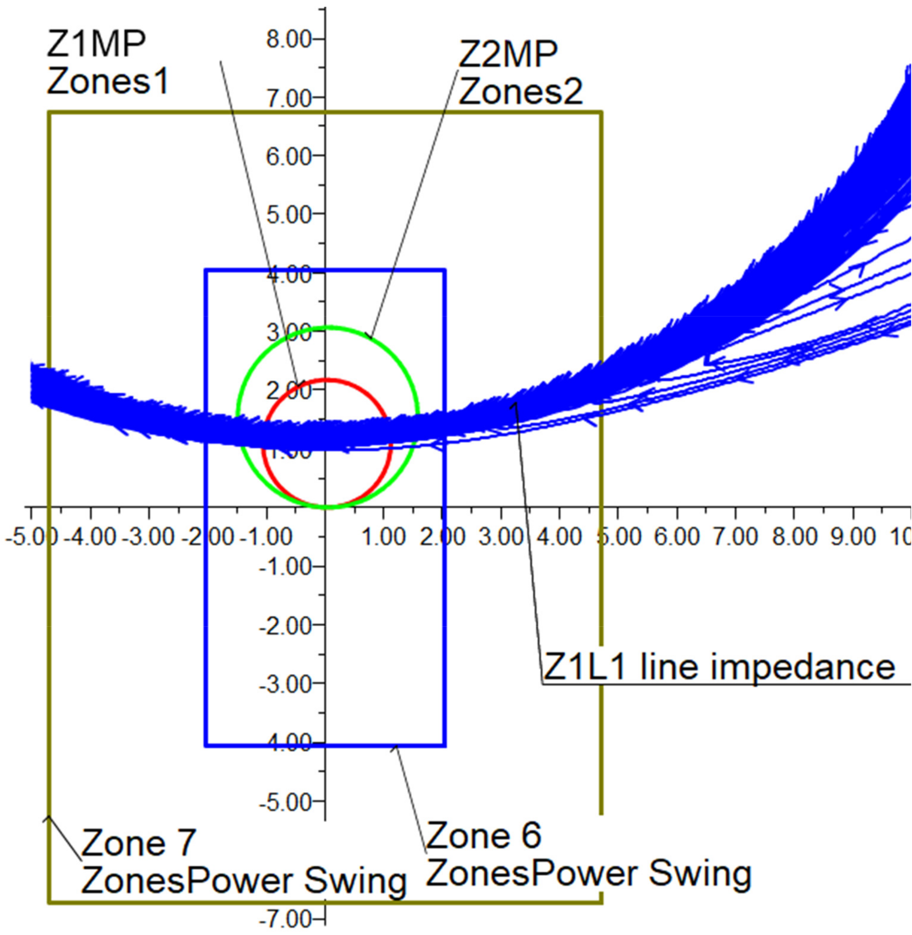
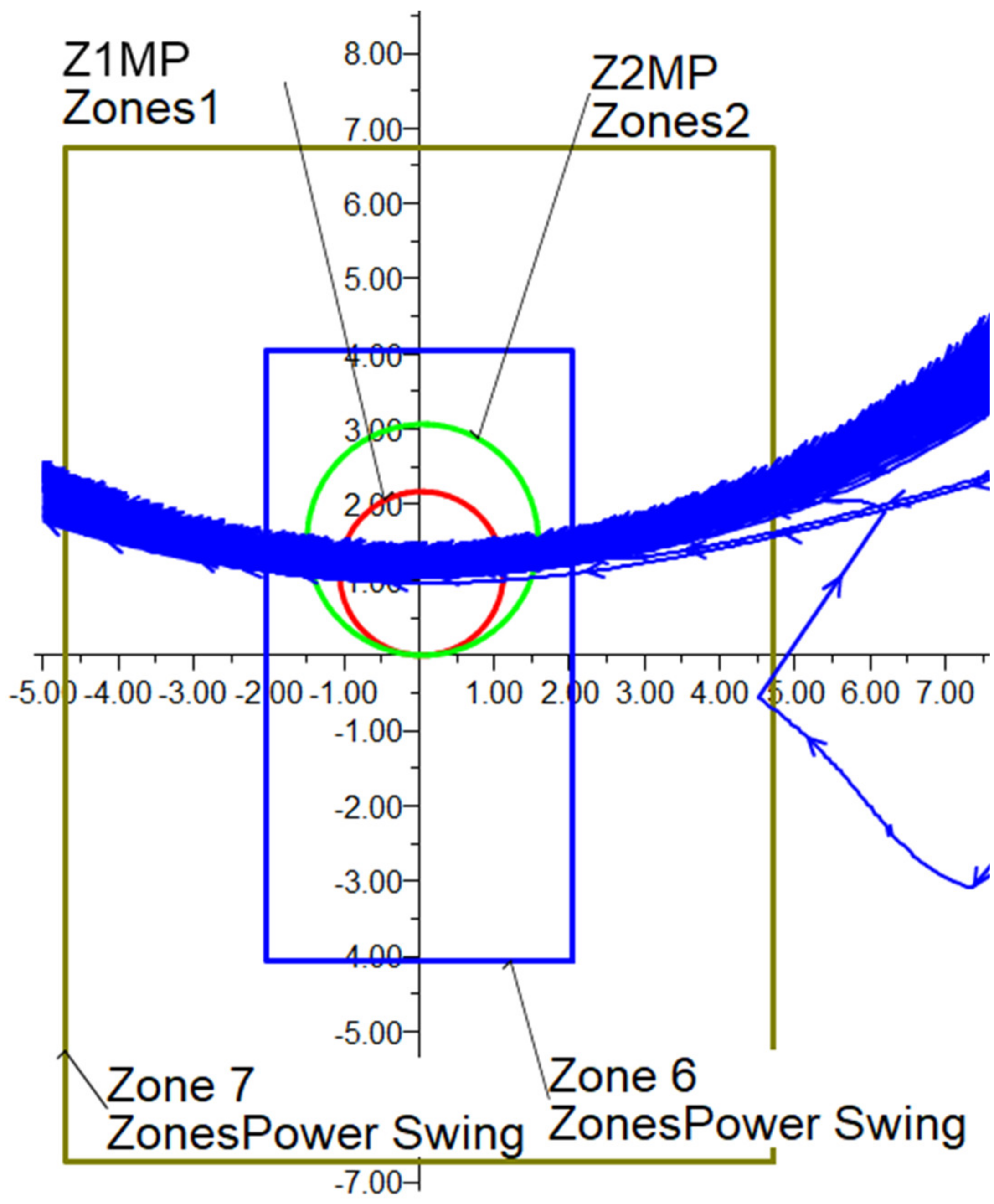
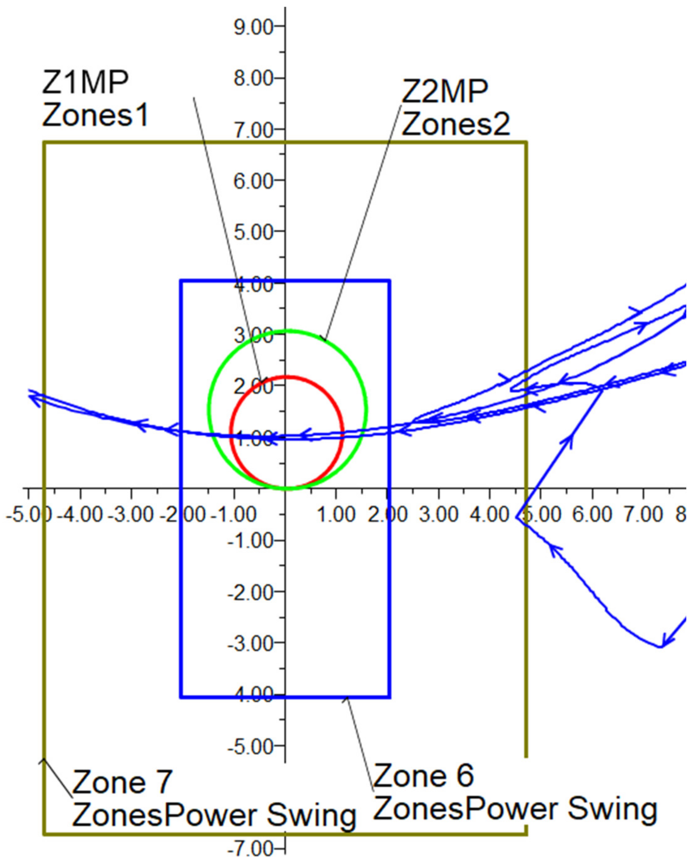
One of the most typical detection schemes for OOS logic uses two zones of concentric polygons, outer Zone 7 and inner Zone 6 (Figure 8). The relay measures a travelling positive-sequence impedance locus (Z1) through Zone 6 and Zone 7 during a power swing or fault [2]. In general, the outermost overreaching zone of phase distance protection is that to be blocked. Then, the innermost reaching Zone 6 (X1T6, R1R6, X1B6, and R1L6) is set to encompass the outermost zone of phase distance protection that has been selected for OOS blocking and set Zone 7 so that the closest minimum load impedance locus is outside the Zone 7 characteristic for all loading conditions [2]. Zone 2 is the outermost characteristic for this particular scenario (see Figure 8), and then a safe marking is included; in this paper, the safe margin is set to 20 per cent, so:
where Z2MP represents the reach of the Zone 2 Phase distance element and Z1ANG is the angle of the positive sequence impedance of the transmission line (Z1). The other three blinders of Zone 6 can be easily obtained by using geometrical properties.
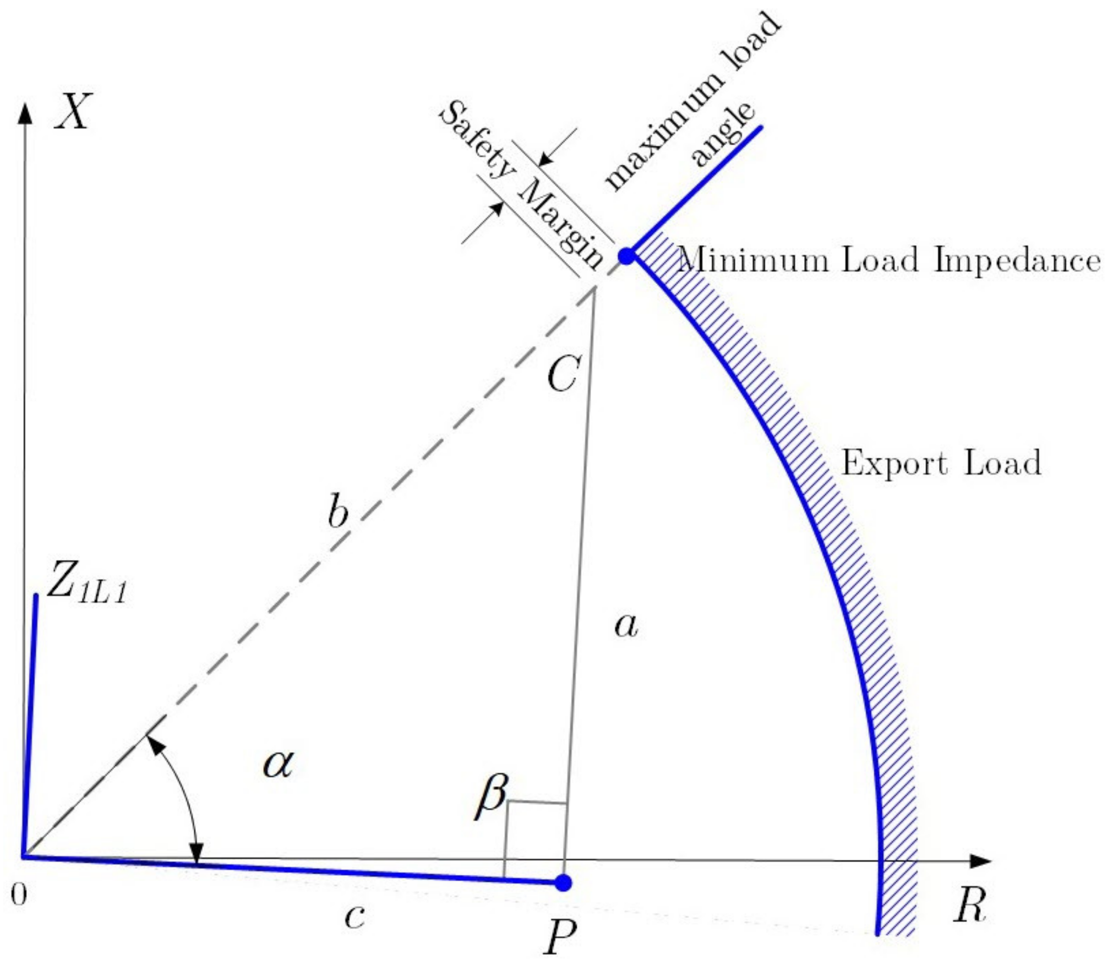
The settings of the Zone 7 outer resistance blinders are based on the maximum load (IL,max). In other words, set the Zone 7 outer right-hand resistance (R1R7) blinder just inside the corresponding minimum export load impedance locus (maximum load locus).
The minimum load impedance that the relay measures (ZLmin):
Using trigonometry and the maximum load angle, the resistive right-side blinder of Zone 2, R1R7 is calculated. R1R7 represents the distance from the origin to the right-hand resistance blinder along with line OP, the c side of the right triangle (see Figure 9). The resistance blinders are parallel to the line characteristic impedance Z1L1 for which the angle is setting Z1ANG.
where:
Rearrange the equation of R1R7 and multiply by a safety factor; in this paper, the safety factor is selected to be 90 per cent to calculate R1R7.
The lines defining Zone 6 are represented by the inner reactance lines X1T6 and X1B6; they should completely encompass the outermost zone of phase distance protection that you want to block from tripping during a power swing [2]. A safety margin must be included; the safety margin of X1T6 is selected to be 20 per cent:
The distance between Zones 6 and 7 top reactance lines should equal the distance between Zones 6 and 7 right-hand resistance blinders. Then,
4.2. Out-of-Step Blocking Time Delay
The logic behind the OOSB time delay is very simple; the relay starts the OOSB timer when the positive sequence impedance (Z1) locus initially moves inside Zone 7. An illustrative example of the positive sequence (Z1) impedance trajectory is shown in Figure 9, for simplicity, the case where the magnitude of the voltage sources equal is selected, k = 1, |Er| = |Es|. The OOSB king delay timer detects slow swings. If the OOS blocking delay timer expires before the Z1 trajectory enters Zone 6, the relay detects a power swing blocking condition [2].
Considering Figure 10, the straight-line section AB represented the total transfer impedance (ZT) between the equivalent voltage sources (Es and Er):
The horizontal dashed line represents the trajectory of the power swing perpendicular to line section AB (k = 1 is assumed). Thus, the trajectory passes through the midpoint of line section AB. Now, applying simple trigonometry, it is simple to derivate the angle when the positive sequence impedance touches the outer Z element (Zone 7) and the inner Z element (Zone 6)—δ7 and δ6 respectively.
Now, the difference between those angles (δ7 and δ6) can be used to determine the time delay to be used as the setting of the OOSB. A typical approach to do so is to obtain the time needed to travel from Zone 7 to Zone 6 (T67) as:
Finally, the time of the OOSB timer setting is adjusted to the nearest valid relay setting.
4.3. Out-of-Step Tripping
Finally, the setting of the OOS tripping is calculated. The OOS tripping (OOST) logic is used to detect an unstable power swing and generate a trip signal to be sent to the local circuit breaker producing the area separation. The OOST logic allows an effective control area separation that enables intentional islanding of the power system at pre-defined locations when a power swing leading to OOS is detected. As presented in the previous sections, the Zone 6 and Zone 7 settings for the OOST logic depend on the positive sequence impedance (Z1) trajectory of the power swing (see Figure 11). The inner Z element at Zone 6 is adjusted based on the point along the positive impedance trajectory where the power system cannot remain stable. The other impedance element, Zone 7, is adjusted by an impedance caused to a maximum load condition (IL,max) which is located outside the Zone 7 characteristic for all loading conditions.
The positive sequence impedance (Z1) trajectory of the power swing defines the Zone 6 and Zone 7 settings for the OST logic depend on.
The setting of the inner impedance zone, Zone 6, is defined by the point along the impedance trajectory where the power system cannot regain stability; the power system is unstable. Then, set the outer impedance zone, Zone 7, so that the impedance due to maximum load conditions is outside the Zone 7 characteristic for all loading conditions.
When the positive-sequence impedance (Z1) trajectory enters Zone 7, both OOS logic timers (OSBD and OSTD) start (see Figure 11). However, if the OOS time delay expires before OOS blocking delay and Zone 6 asserts, the relay declares an out-of-step tripping condition. As OOS function is to configure the relay to trip when the power system reaches a critical angle limit to prevent system collapse, the Zone 6 impedance setting differs from OOS blocking.
Initially, the resistance blinders for zones 6 and 7 are calculated. It is recognised that if the angle of the power swing in the positive sequence impedance (Z1) passes the 120° with respect to the transfer impedance (ZT), the power system will not recover from the power system, and an OOS condition is reached. The right-hand inner resistance blinder of Zone 6, R1R6 is set in order that the angle δ6 = Ang R6 = 120°.
The right-hand resistance blinder of Zone 7 is set based on the minimum load impedance ZL,min and a safety margin. In this paper, the safety margin is selected to 90 per cent, therefore, the resistance blinder R1R7 results:
Now the reactance lines must be defined for zone 6 and 7. A typical mechanism is to set the reactance lines equal to the maximum reactance values to help the relay detect power swings far from the relay location. Therefore, the Zone 7 reactance (X1T7) is set equal to the maximum setting in the relay; the idea is to make a rectangle as high as possible.
On the other hand, the Zone 6 reactance is set equal (X1T6) to the Zone 7 reactance (X1T7) minus a small reactance separation merging; in this paper, the separation margin (Xmargin) is selected to be 1 Ω.
Finally, there are two methods to trip during an unstable swing. First, enable the relay to trip if OOS time delay expires, and the positive-sequence impedance enters Zone 6; this method is Trip-On-the-Way-In (TOWI in Figure 11) [2]. Second, enable the relay to trip if OOS time delay expires, and the positive sequence impedance enters and exits Zone 6; this second method is Trip-On the-Way-Out (TOWO in Figure 11). The TOWO is the most desirable method; it allows for the tripping of the circuit breaker to take place in a more favourable time, during the slip cycle when the two systems are close to an in-phase condition.
4.4. Out-of-Step Tripping Time Delay
Finally, the OOS tripping time delay must be defined; the process is similar to the one used in Section 4.2, OOS blocking time delay with reference to Figure 10.
Considering the total transfer impedance (ZT), as defined in (13), is used to specify the angle of the δ7 and δ6. δ6 = Ang R6 = 120° (see Section 4.2). The angle R7 (δ7) is calculated as:
The difference between those angles (δ7 and δ6) is used to define the OOS tripping time delay. A typical approach to do so is to obtain the time needed to travel from Zone 7 to Zone 6 () as:
Finally, the time of the OOS tripping time delay setting is adjusted to the nearest valid relay setting.
4.5. Out-of-Step Unblocking during Three-Phase Faults
The trajectories of a three-phase fault and a power swing appear the same to phase distance elements because both a three-phase fault and a power swing consist of positive-sequence quantities only (V1 and I1) [2]. Therefore, if a power swing evolves into an internal three-phase fault, typical OSB logic cannot detect the occurrence of the balanced fault [2]. Digital relays include an additional set of inner blinders to provide proper detection of the internal three-phase fault [2]. If the positive-sequence impedance resides between these blinders for a specific duration, OSB logic unblocks [2]. The relay calculates this duration each time the power swing enters Zone7. Thus, a short-timer setting is adequate for fast swings, but the relay needs a more extended timer setting for slow power swings [2].
5. Illustrative Example and Demonstration of Settings Calculations: A Step-by-Step Process
This section is dedicated to illustrating and demonstrating the proposed step-by-step process to defining the settings of the OOS presented in the previous section. The test system is a traditional single machine connected through a transmission system to an infinite busbar (see Figure 12). It represents a 2200 MVA power plant connect to a relatively large equivalent power system (infinite bus) using a 500 kV double circuit transmission system. The test system can be considered as two equivalent sources presented in Figure 1; the task in this section is to illustrate the step-by-step process of calculating the OOS protection relay settings. For illustrative purposes, the model of a real relay SEL-421 from Schweitzer Engineering Laboratories is installed in CCT-1 (details of the CT and VT are shown in Figure 12 and numerical values in Table 1).
Step 1: OOS blocking
The innermost reaching Zone 6 is set to encompass the outermost zone of phase distance protection that has been selected for OOS. Using (10) and considering a 20 per cent safety margin:
The maximum load current is ILmax = 4.71 A (measured at the secondary of the CT); this value is typically obtained from a power flow analysis. The corresponding line-to-neutral voltage during maximum load at HT side is VLN = 61.44 V secondary; using this data, the minimum load impedance (ZLmin) that the relay measure can be obtained using (11):
It is assumed that the maximum load angle is 45°. The setting of the blinder (R1R7) in Zone 7 is calculated by using (13):
The Zone 6 inner reactance lines X1T6 and X1B6 should completely encompass the outermost zone of phase distance protection that it is wanted to be blocked from tripping during a power swing. The reactance lines of Zone 6 and 7 are calculated by using (14) and (15), respectively:
and,
Step 2: OOS block Time Delay
The angles δ6 and δ7 are calculated by using (17) and (18):
Finally, by using (19), (31), and (32) and considering a fslip = 5.0 Hz, the setting OOS blocking delay results:
Considering digital relay SEL-421 has restrictions in settings increments, a round up to the nearest valid relay setting. In this case, OSBD = T76 = 1.5 cycles.
Step 3: OOS tripping
The Zone 6 right-hand inner resistance blinder R1R6 is set so Ang_R6 equals δ6 = 118.34°, using (20):
Using the minimum load impedance in (21), 13.04 ohms and the 90 per cent safety margin criterion (4) applied previously in resistance blinders to set the Zone 7 right-hand resistance blinder, the R1R7 setting is:
The Zone 7 reactance (X1T7) is set to equal to the maximum setting in the relay; in this case, the SEL-421 allows 96 Ω.
The X1T6 setting is calculated by using (23):
Step 4: OOS Tripping Time Delay
Equations (24) to (25) are used to calculate the OOS tripping delay:
Considering a fast unstable swing frequency and calculate the OOS tripping delay(for this paper, assumed fslip = 10 Hz for an unstable power swing).
Round up to the nearest valid relay setting, then OSBD = = 1.0 cycles.
A summary of all the settings calculated for the SEL421 are shown in Table 2.
5.1. Testing the Proposed Settings
The previous section illustrated the proposed step by step process of defining the settings of the OOS protection relay using a SMIB test system (Figure 12). Now, this section is exclusively dedicated to demonstrating the suitability of the proposed settings. To do that in a more realistic way, the test system has been implemented in power system analysis software, specifically DIgSILENT® PowerFactoryTM version 2021a. The OOS protection is tested by using time-domain simulations using RMS functionality in the software. The SEL-421 relay model is included in the global library of PowerFactory (see Figure 13), and it allows a high-fidelity reproduction of the performance of the relay during the tests. The following subsections present the numerical results and discussion of the digital simulations.
To investigate the OOS and power swing, a model of the two sources 500 kV system was implemented and simulated using the software DIgSILENT PowerFactory, and SEL-421 relay model was used (Figure 13). The SEL-421 PowerFactory relay model consists of the main model and sub-relay hosting the OOS relay as well as the model versions are available: SEL-421–1A and SEL-421–5A. In this paper, the model of the SEL-421–5A is used. Three measurement units (“M-I/U”,” M-Iab/Ibc/Ica” and” Meas RMS seq” block) are fed by this CT and this VT [3]. The OOS relay consists of the OOS and the power swing detection logic [3]. Two polygonal zones are defining the power swing detection area (“Zone 6” and “Zone 7” block), one minimum current activation threshold (“I supervision” block), one power swing and OOS detection element (“Out of Step” block) and one-timer associated to the OOS trip signal (“OS Time Delay” block). The output logic is the interface between the relay and the system model. A set of twenty-two relay output signals is available and can be configured by the user to implement any control logic.
5.1.1. Test 1: OOS Protection in Power Swing Condition Cause by Transfer Capability Limit
The first test used to show the suitability of the proposed approach is based on exciting a power swing by a single contingency at the transmission system. The disturbance used was the sudden disconnection of the CCT-2 transmission line in order to detect power swing or OOS in the system due to the CCT-1 line carrying over its transfer capability.
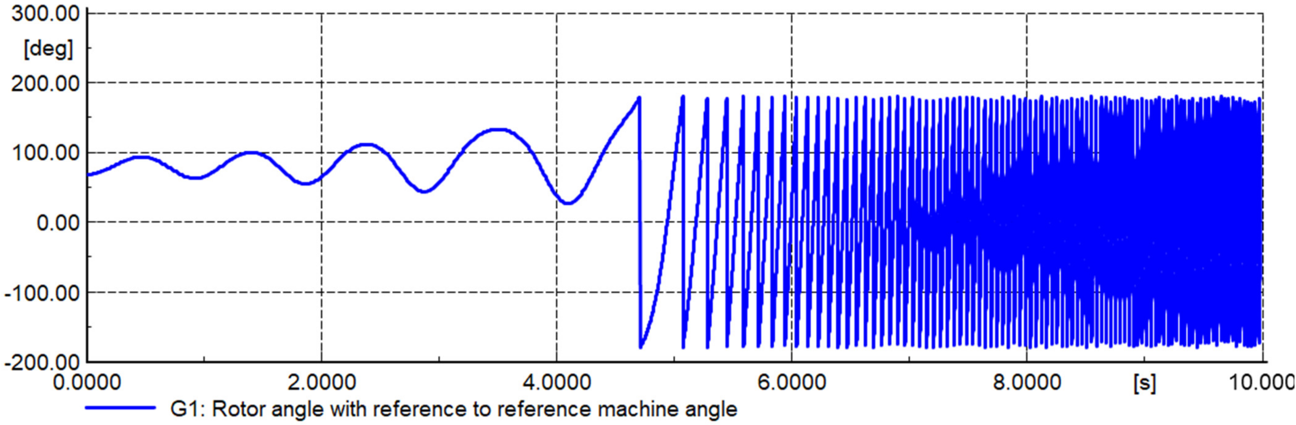
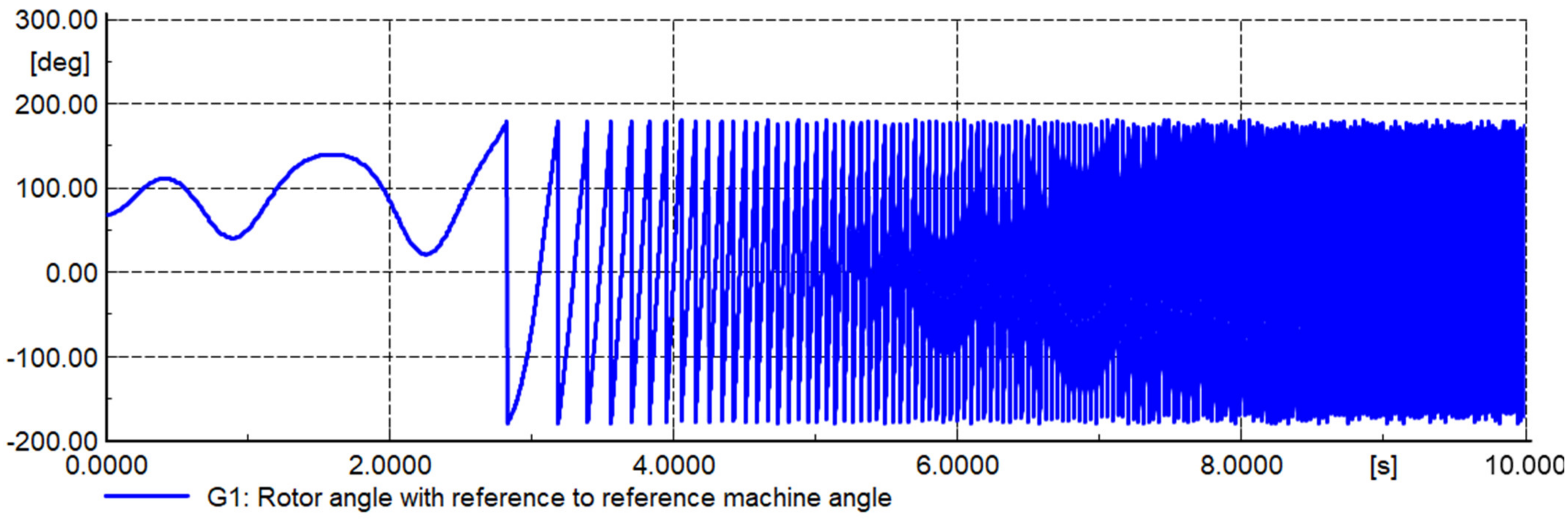
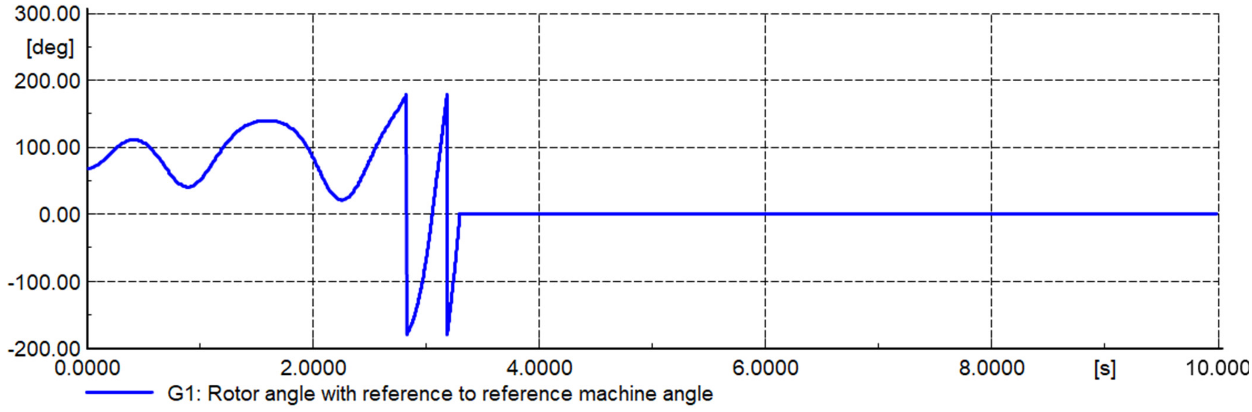
In steady-state operation, the CCT-1 line was transferring 1299.4 MW from HV bus to infinite bus and loading 92.6%. Immediately after the disturbance, CCT-1 line is carrying 1988.1 MW, and loading by 148.6% as well as power swing has appeared in the system. If, during this contingency, the CCT-1 line has no installed OOS protection that the power system will be unstable. In this case, the G1 generator cannot remain in synchronism because the rotor angle of the machine was continuously increased to reach ±180 degrees over the simulated duration of 4.709 s (see Figure 14). Otherwise, if the CCT-1 line is installed the OOS protection that is successful cleared power swing centre; as a result, the generator is not working a long time during the unstable oscillations, and G1 generator is still remained working with the system in synchronism (Figure 15). The plots of the simulation results are included in Figure 14, Figure 15, Figure 16 and Figure 17.
5.1.2. Test 2: Out of Step Protection in Unstable Oscillation Condition Caused by A Short Circuit
The first test used to show the suitability of the proposed approach is based on exciting a power swing by considering a large disturbance; in this case bolted three-phase fault short circuit is applied on the CCT-2 transmission line, where relay protection is cleared fault by 200 msec. In this case, G1 generator is lost synchronously started around 2.2 s, although CCT-2 line protection is cleared the fault. Therefore, the OOS relay is installed on the CCT-1 line and activates the OOS trip logic after that same disturbance was applied on the CCT-2 line. In this situation, the G1 generator prevent unstable oscillation and remains in the synchronism operation. The plots of the simulation results are included in Figure 18, Figure 19, Figure 20 and Figure 21.
6. Settings of OOS and Testing: The Mongolian Power System Case
The proposed methodology has been presented in Section 4, after which a simple test system was used to illustrate the approach and then simulation results demonstrated its suitability. However, the proposed methodology is intended to be applied and thoroughly tested in the real case of the Mongolian Power System.
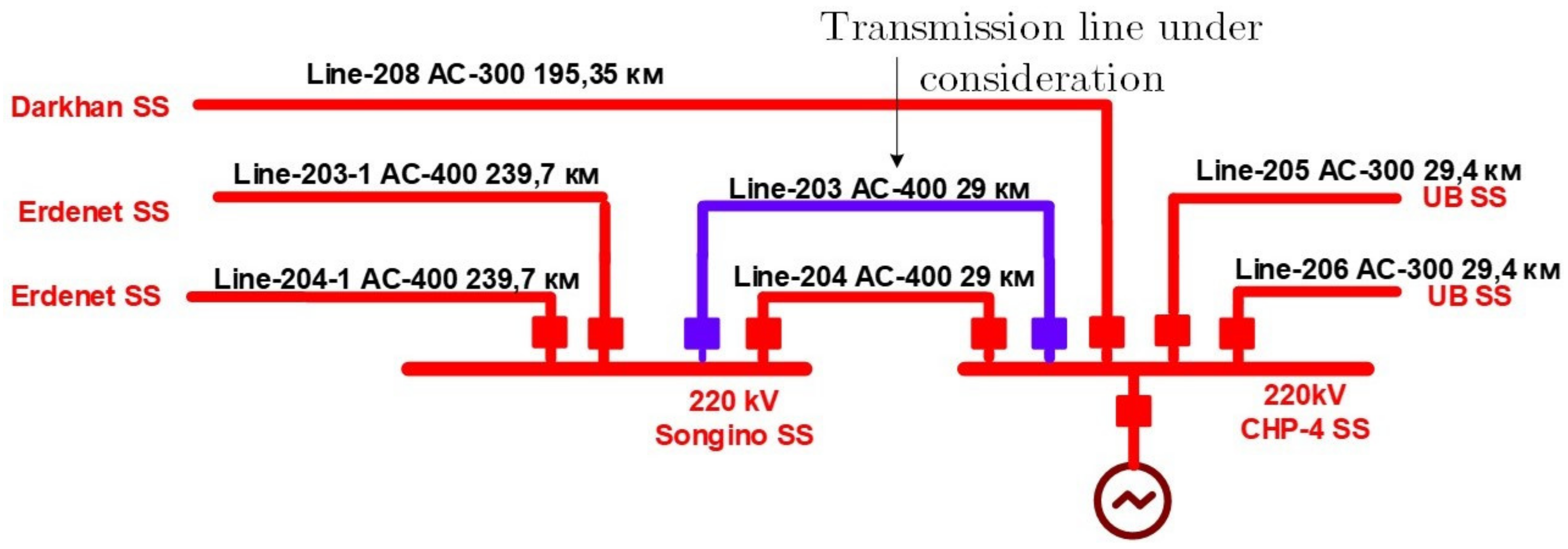
This section focuses on defining the appropriate settings of the OOS protection relay installed in the Line-203 interconnecting the 220 kV Songino SS substation and the largest power plant in Mongolia (the CHP-4 substation (at 220 kV)), see Figure 22. Line-203 is the transmission line under consideration for the remaining part of this paper for the OOS settings as this line was involved in the major event of 15 September 2018.
On 15 September 2018 at 09:30:14:59 (Mongolia local time), the single line to a ground fault (phase b) occurred at 220 kV busbar side of the substation CHP-4; this substation is the step-up station of the biggest thermal power plant in Mongolia. The busbar protection installed at the CHP-4 substation 220 kV side successfully cleared the fault in 90 ms. However, the key 220 kV lines and generators were obviously disconnected at CHP-4 by bus protection. Immediately after the events, import power was increased from the Russian grid; at the Mongolian power system (MPS) side, the 220 kV single circuit 203 line quickly became overloaded and power oscillations were excited, and line 203 was tripped by OOS protection. The existing OOS protection at that moment was based on a mechanical relay, and the setting is line impedance cross four times for 3.5 s.
The proposed approach shows Section 4 has been used to define the settings of the OOS protection installed in Line-203 and considers the use of the digital protection relay SEL-421.
6.1. Testing Settings OOS Using Time-Domain Co-Simulations
This section is dedicated to testing the suitability of the proposed settings of the OOS protection relay installed in Line-203 (see Table 3). The full detailed model of the Mongolian power system is implemented in the DIgSILENT PowerFactory simulation environment. The network model includes all details for performing rotor angle stability studies, including protective devices.
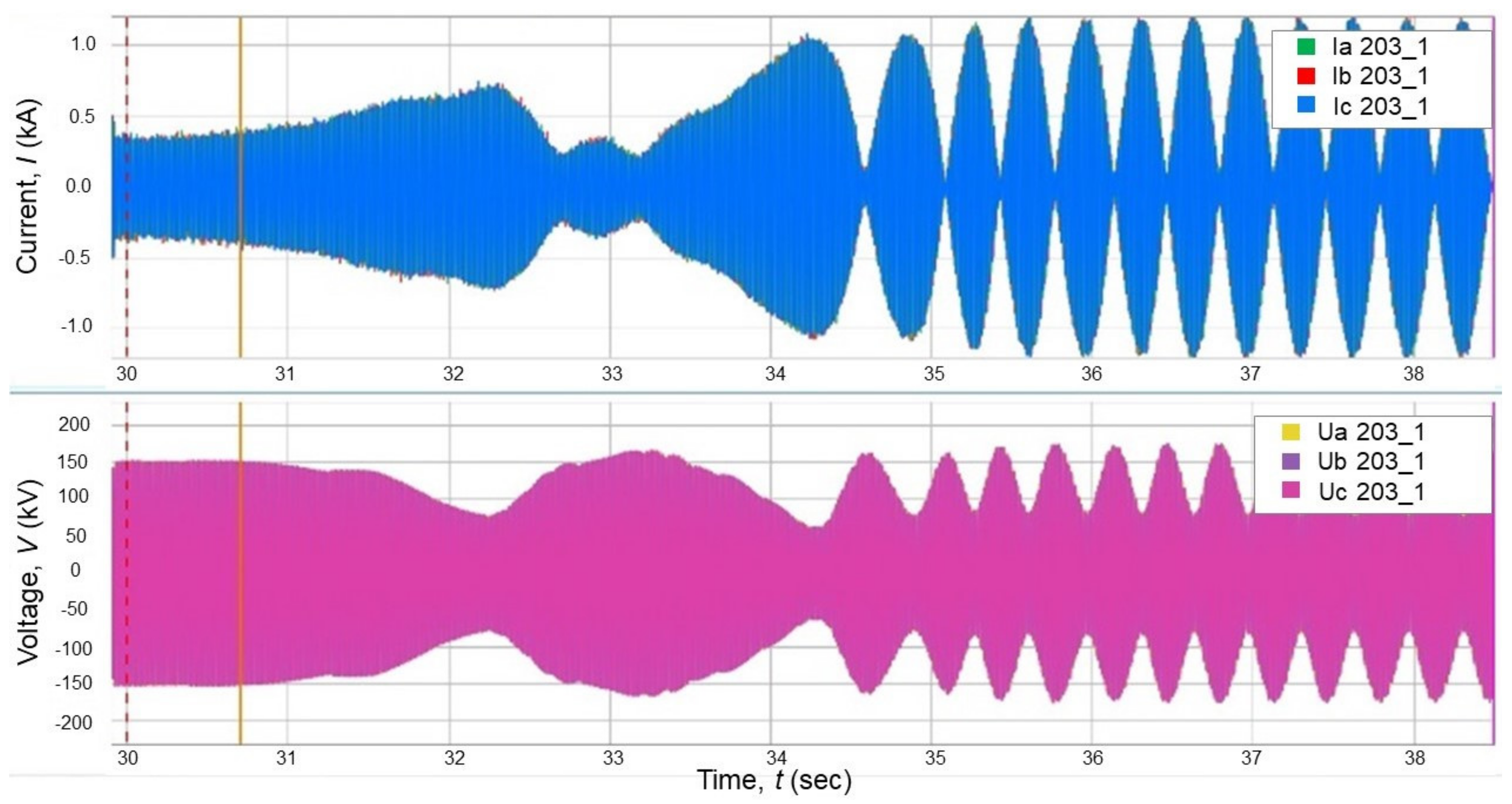
This section takes advantage of the data recorded during the major event on 15 September 2021 in Line-203, see Figure 23. The recorded time series has been appropriately post-processed and used to inject the signals into DIgSILENT PowerFactory; as a consequence, a hybrid co-simulation framework has been created. The idea of the co-simulation framework is to use the signals created by the real behaviour of the power system and inject them into the digital simulation environment to test the OOS protection setting.
The hybrid co-simulation framework is used to perform rotor angle stability studies to assess the proposed OOS protection settings. The idea of the test is to identify the number of impedance crosses of the power swing in the OSS protection scheme.
Initially, the actual OOS protection scheme electromechanical relay is tested if the existing OOS protection is tripped after 5.35 s, it is recognised six to seven times unstable oscillation accounted during that time, as a consequence, the synchronous generator must be disconnected to avoid any potential damage. Therefore, OOS protection should work when the impedance crosses power swing areas one, two or three times to decrease the risk of damage to the generator and avoid cascading events.
Taking into consideration the same conditions of the 15 September 2018 event, the system has already recognised the unstable power swing as it was difficult to remain in a stable condition. To avoid the unstable condition, the OOS protection should provide a fast trip of transmission line 203 when the OOS power swing is detected. This will allow the synchronous generator to reach unstable operating conditions and prevent a cascading event of generators. If OOS protection is able to trip Line 203 and successfully separates the two systems, the power swing is cleared. However, the loss in feed from the Russian system will create a frequency stability issue. In this paper, the existing UFLS is also considered after the MPS becomes an island as a consequence; the frequency stability issue is addressed by the UFLS (more details of the UFLS scheme installed in Mongolia in [28]).
After the operation of the OOS protection, the system frequency reached 47.14 Hz is then recovered to 50.91 Hz by UFLS. Otherwise, if OOS protection fails to act delayed, generators must be disconnected from the grid due to overexcitation, loss of field protection or maloperation of the protection device. In this case, the system can be realised as a more unstable power swing due to a massive active and reactive power deficit. Therefore, the future MPS will be used to the proposal set of OOS protection that generators can work at for a maximum of 1.5 s and are recognised for two to three times the power swing under this kind of disturbance. The co-simulation results considering the existing settings of the OOS protection at Line 203 are shown in Figure 24 and Figure 25. The proposed settings are tests, and the results are shown in Figure 26 and Figure 27, demonstrating the suitability of the proposed approach.
6.2. Testing Settings OOS Using Cyber-Physical Approach
Finally, this section is dedicated to testing the proposed setting using a cyber-physical approach. A classical secondary injection test is performed on the real SEL-421 devices using the appropriate signals. This section uses automated OMICRON tests to the proposed OOS setting shown in Table 3. A field digital fault recorder installed at Line-203 was able to record the substantial power swing that took place on the network of a Mongolian country on 15 September 2018 and lasted for about 10 s.
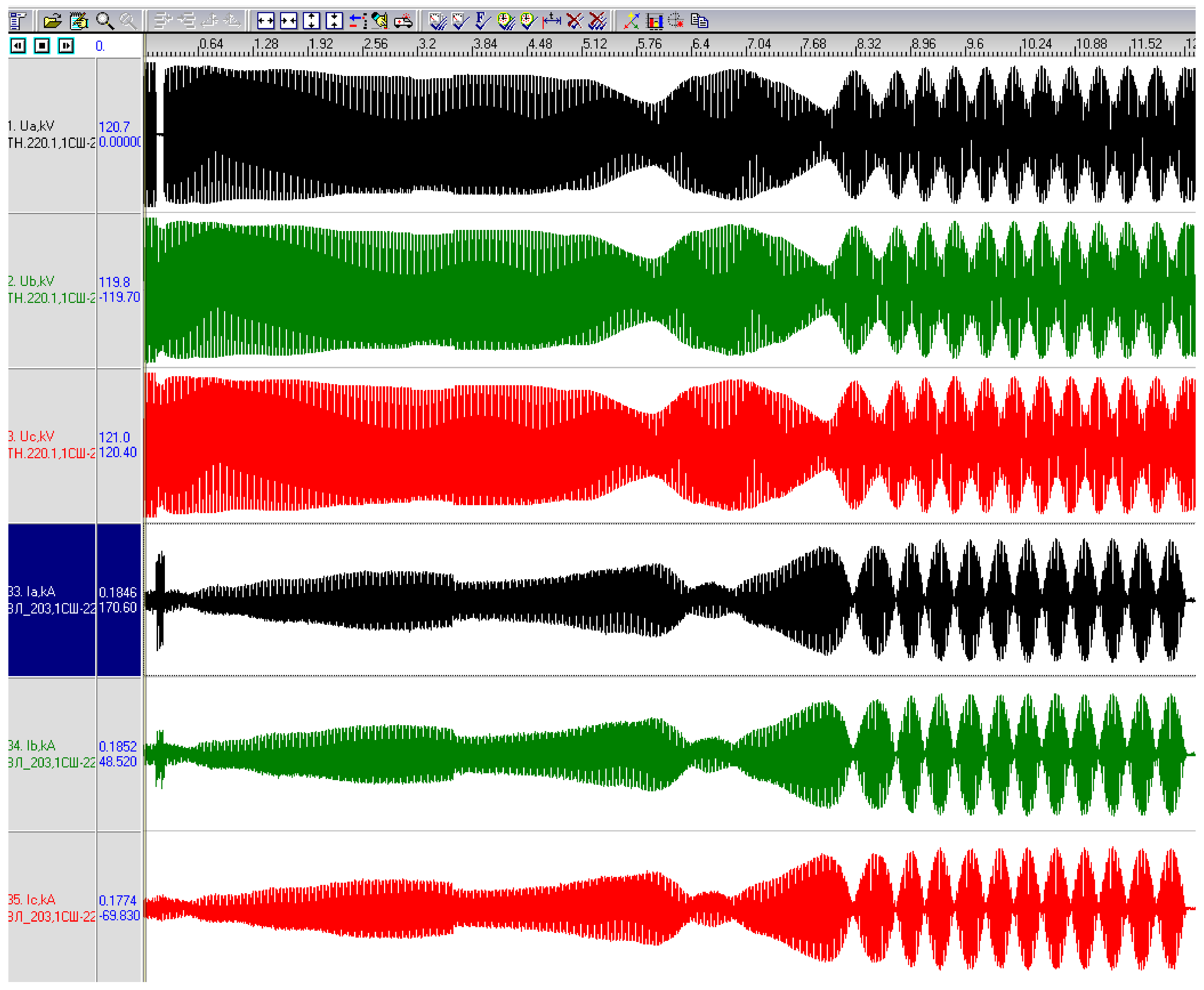
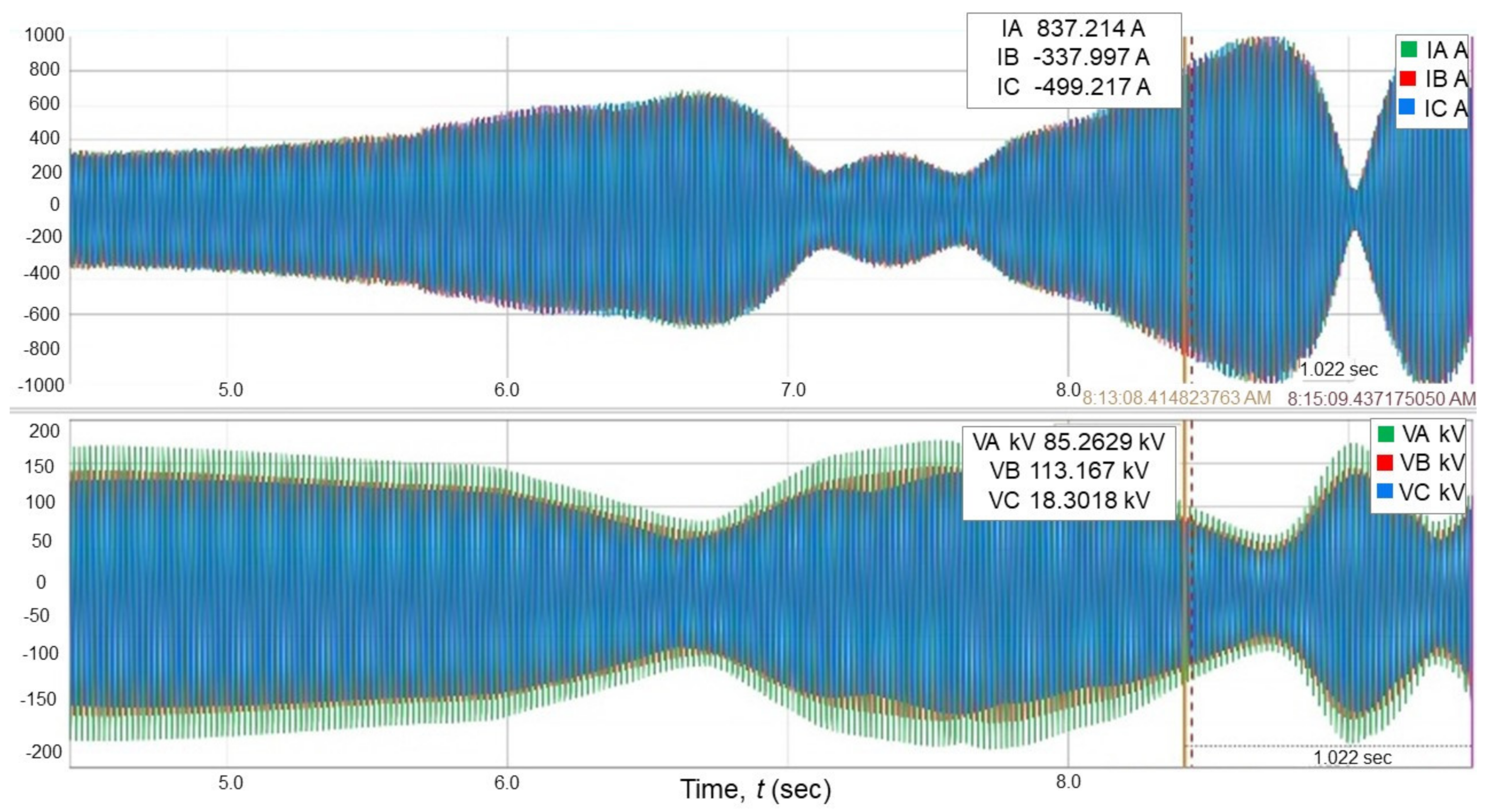
Although the power swing was unstable and the existing OOS protection cleared it, the OOS protection took approximately 4.5 s and five slip cycles to clear the unstable swing. As a consequence, the Mongolian power system was exposed to unacceptable operating conditions. Consequently, the generating unit-2 the shaft was damaged at the CHP-4 generation plant that day due to the unstable oscillations created. Figure 28 illustrates the line voltages and currents recorded by the 220 kV transmission line during the unstable power swing.
The data captured by fault recorder JSC EC Continuum PMU-101 during the event of 15 September 2018 at line 203 consisted of voltages and currents during the power swings; the data series were appropriately exported using the COMTRADE format. The recorded data in the form of files are used as input to the OMICRON Universal Test software in order to replicate the time domain voltage a current signals using the OMICRON CMC-356.
The test set OMICRON CMC-356 has been appropriately wired to the SEL-421 and the voltage signals used as input to the CT and VT terminals of the relay, to close the loop of the test, the SEL-421 binary outputs are connected to the OMICRON CMC-356 providing signals such as alarm, trip signal, etc.
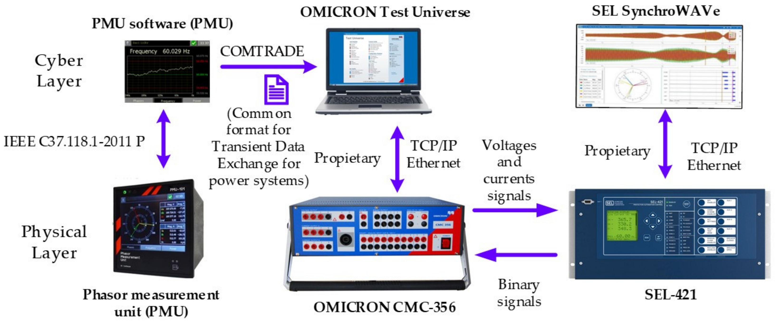
This test set allows to use of the voltages and currents from the real unstable event of 15 September 2018 into the protection relay SEL-421 and test the suitability of the OOS settings. The property software of SEL, the AcSELerator and fault analyser SynchroWAVe event are used to set the relay and capture and process the response (see Figure 29).
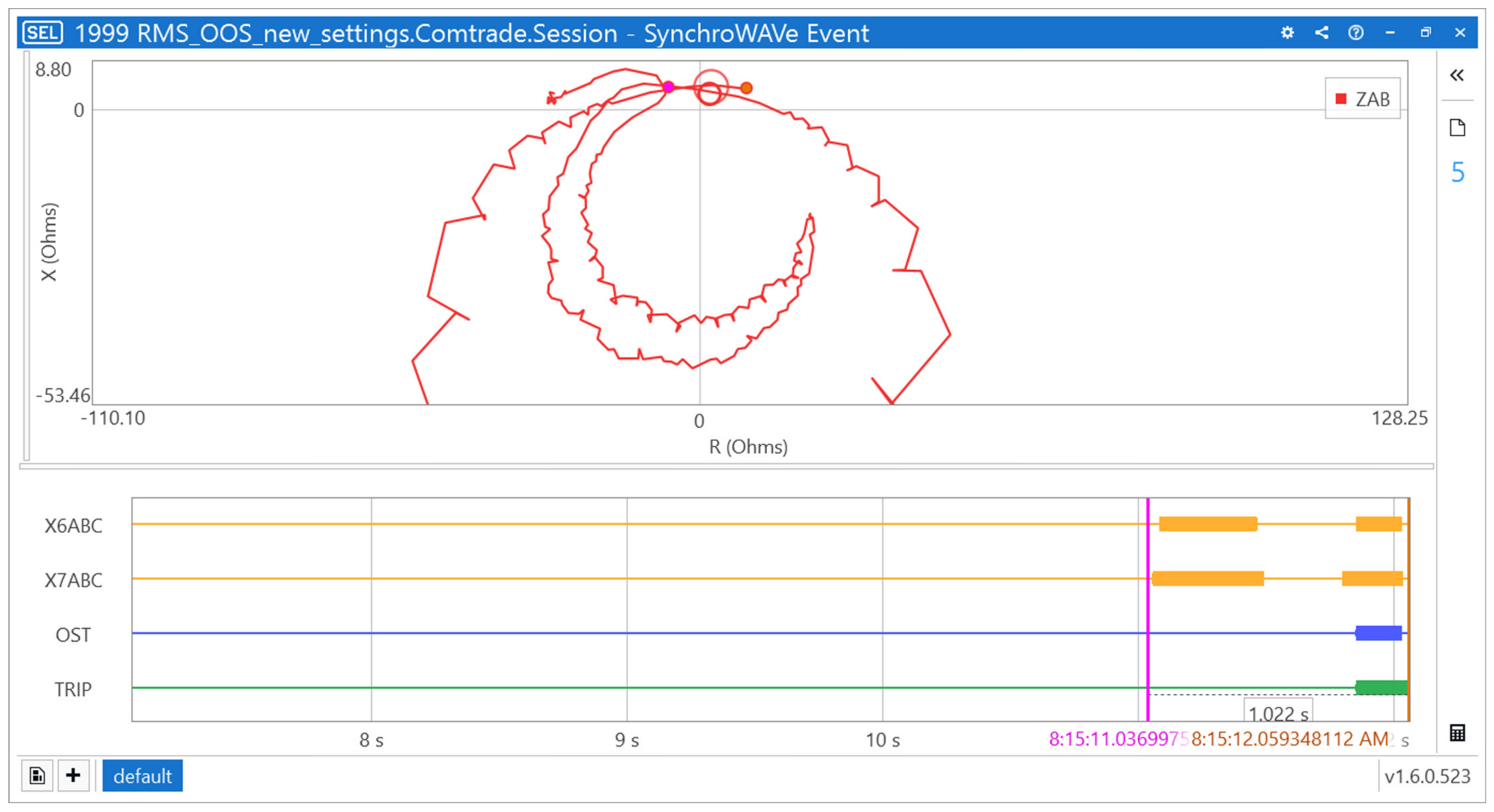
The testing using the cyber-physical approach focus on investigating the suitability of the proposed OOS settings. Currents and voltages of the power swings are transferred to SEL-421 by OMICRON; results show the unstable power swing and as the impedance passes through the inner and outer blinders, X6ABC and X7ABC, respectively. Also, as shown in Figure 30 and Figure 31, the unstable power swing was cleared in approximately 1.022 s, which equals the detecting power swing in Zone 6 and Zone 7 and, plus the time of the trip signal. In this case, the power system would be operating for 1.5 slip cycles under abnormal unstable conditions. Consequently, that proposal setting of OOS protection can reduce slip cycles almost four times. As a result, generators would be worked in less unstable conditions than using that based on mechanical relay OOS protection.
7. Conclusions
This paper presented and tested a detailed step-by-step method for the calculations of the setting of OOS protection, including both blocking and tripping functions, considering a generic two-source system. Then the method was applied to define the protection relay settings installed at the interconnection between the Russian and Mongolian power systems, specifically the transmission Line 203 at 220 kV. In this paper, the impedance method was used for defining the OOS protection settings. This paper innovates by testing the proposed settings using the recordings of the major events of 15 September 2018 in two approaches: hybrid co-simulation and a cyber-physical approach. The hybrid co-simulation framework is used to perform rotor angle stability studies and assesses the proposed OOS protection settings. The idea of the test was to identify the number of impedance crosses of the power swing in the OSS protection scheme. The full detailed model of the Mongolian power system is implemented in the DIgSILENT PowerFactory simulation environment; the data recorded during the major event on 15 September 2021 in Line-203 was appropriately post-processed and used to inject the signals into DIgSILENT PowerFactory; Also, a cyber-physical approach was used to assesses the proposed OOS protection settings. The approach uses a combination of recorded signals from the major event on 15 September 2021. Those signals have been injected using OMICRON CMC-356 to the real SEL-421. Both tests have demonstrated the appropriate performance of the proposed settings and proved that the proposed methodology works appropriately.
Author Contributions
Conceptualisation, F.G.-L., C.A. and E.V.M.; methodology, F.G.-L., C.A. and E.V.M.; software, F.G.-L., C.A. and E.V.M.; validation, F.G-.L., C.A. and E.V.M.; formal analysis, F.G.-L., C.A. and E.V.M.; investigation, F.G.-L., C.A. and E.V.M.; resources, F.G.-L., C.A. and E.V.M.; data curation, F.G.-L., C.A. and E.V.M.; writing—original draft preparation, F.G.-L., C.A. and E.V.M.; writing—review and editing, F.G.-L., C.A. and E.V.M.; visualisation, MNA, F.G.-L.; supervision, F.G.-L. All authors have read and agreed to the published version of the manuscript.
Funding
This research received no external funding.
Institutional Review Board Statement
Not applicable.
Informed Consent Statement
Not applicable.
Data Availability Statement
Not applicable.
Conflicts of Interest
The authors declare no conflict of interest.
References
- Kundur, P.; Balu, N.J.; Lauby, M.G. Power System Stability and Control; McGraw-Hill: New York, NY, USA; London, UK, 1994; ISBN 007035958X. [Google Scholar]
- Acosta, M.N.; Gonzalez-Longatt, F.; Topić, D.; Andrade, M.A. Optimal Microgrid–Interactive Reactive Power Management for Day–Ahead Operation. Energies 2021, 14, 1275. [Google Scholar] [CrossRef]
- Chamorro, H.R.; Orjuela-Cañón, A.D.; Ganger, D.; Persson, M.; Gonzalez-Longatt, F.; Alvarado-Barrios, L.; Sood, V.K.; Martinez, W. Data-Driven Trajectory Prediction of Grid Power Frequency Based on Neural Models. Electronics 2021, 10, 151. [Google Scholar] [CrossRef]
- Kundur, P.; Paserba, J.; Ajjarapu, V.; Andersson, G.; Bose, A.; Canizares, C.; Hatziargyriou, N.; Hill, D.; Stankovic, A.; Taylor, C.; et al. Definition and Classification of Power System Stability IEEE/CIGRE Joint Task Force on Stability Terms and Definitions. IEEE Trans. Power Syst. 2004, 19, 1387–1401. [Google Scholar] [CrossRef]
- Chamorro, H.R.; Sevilla, F.R.S.; Gonzalez-Longatt, F.; Rouzbehi, K.; Chavez, H.; Sood, V.K. Innovative primary frequency control in low-inertia power systems based on wide-area RoCoF sharing. IET Energy Syst. Integr. 2020, 2, 151–160. [Google Scholar] [CrossRef]
- Sanchez, F.; Gonzalez-Longatt, F.; Bogdanov, D. Probabilistic assessment of enhanced frequency response services using real frequency time series. In Proceedings of the 2018 20th International Symposium on Electrical Apparatus and Technologies (SIELA), Bourgas, Bulgaria, 3–6 June 2018; pp. 1–4. [Google Scholar]
- IEEE. IEEE Tutorial on Protection of Synchronous Generators. 2011. Available online: https://www.pes-psrc.org/kb/published/reports/IEEEGenProtTutorial_20110506_1file.pdf (accessed on 10 October 2021).
- IEEE. IEEE C37.102-2006: Guide for AC Generator Protection. 2007; Volume 2000, ISBN 0738152501. Available online: https://0-ieeexplore-ieee-org.brum.beds.ac.uk/stamp/stamp.jsp?arnumber=4534870 (accessed on 10 October 2021).
- Tziouvaras, D.A. Daqing Hou Out-of-step protection fundamentals and advancements. In Proceedings of the 57th Annual Conference for Protective Relay Engineers, College Station, TX, USA, 1 April 2004; pp. 282–307. [Google Scholar]
- Hinojosa, V.; Mar, S.; Gonzalez-longatt, F. Stochastic security-constrained generation expansion planning methodology based on a generalized line outage distribution factors. In Proceedings of the 2017 IEEE Manchester PowerTech, Manchester, UK, 18–22 June 2004; pp. 1–6. [Google Scholar] [CrossRef] [Green Version]
- Alhejaj, S.M.; Gonzalez-Longatt, F.M. Investigation on grid-scale BESS providing inertial response support. In Proceedings of the 2016 IEEE International Conference on Power System Technology, Powercon 2016, Wollongong, NSW, Australia, 28 September–1 October 2016. [Google Scholar]
- Rueda, J.L.; Erlich, I.; Gonzalez-Longatt, F. Performance assessment of evolutionary algorithms in power system optimization problems. In Proceedings of the 2015 IEEE Eindhoven PowerTech, PowerTech 2015, Eindhoven, The Netherlands, 29 June–2 July 2015. [Google Scholar]
- Gorostiza, F.S.; Gonzalez-Longatt, F. Optimised TSO-DSO interaction in unbalanced networks through frequencyresponsive EV clusters in virtual power plants. IET Gener. Transm. Distrib. 2020, 14, 4908–4917. [Google Scholar] [CrossRef]
- Rakhshani, E.; Perilla, A.; Torres, J.R.; Longatt, F.G.; Soeiro, T.B.; Van Der Meijden, M. FAPI Controller for Frequency Support in Low-Inertia Power Systems. IEEE Open Access J. Power Energy 2020, 7, 276–286. [Google Scholar] [CrossRef]
- Ding, L.; Gonzalez-Longatt, F.M.; Wall, P.; Terzija, V. Two-step spectral clustering controlled islanding algorithm. IEEE Trans. Power Syst. 2013, 28, 75–84. [Google Scholar] [CrossRef] [Green Version]
- Cresap, R.L.; Haner, J.M.; Hill, L.A.; Mittelstadt, W.A. A new out-of-step relay with rate of change of apparent resistance augmentation. IEEE Trans. Power Appar. Syst. 1983, PAS-102, 631–639. [Google Scholar] [CrossRef]
- Taylor, C.W.; Haner, J.M.; Hill, L.A.; Mittelstadt, W.A.; Cresap, R.L. A New Out-of-Step Relay with Rate of Change of Apparent Resistance Augmentation. IEEE Power Eng. Rev. 1983, PER-3, 32. [Google Scholar] [CrossRef]
- Zhang, S.; Zhang, Y. Characteristic Analysis and Calculation of Frequencies of Voltages in Out-of-Step Oscillation Power System and a Frequency-Based Out-of-Step Protection. IEEE Trans. Power Syst. 2019, 34, 205–214. [Google Scholar] [CrossRef]
- Zhang, S.; Zhang, Y. A Novel Out-of-Step Splitting Protection Based on the Wide Area Information. IEEE Trans. Smart Grid 2017, 8, 41–51. [Google Scholar] [CrossRef]
- Paudyal, S.; Ramakrishna, G.; Sachdev, M.S. Application of equal area criterion conditions in the time domain for out-of-step protection. IEEE Trans. Power Deliv. 2010, 25, 600–609. [Google Scholar] [CrossRef]
- Wang, L.; Girgis, A.A. A new method for power system transient instability detection. IEEE Trans. Power Deliv. 1997, 12, 1082–1088. [Google Scholar] [CrossRef]
- Rovnyak, S.; Thorp, J.; Kretsinger, S.; Brown, D. Decision Trees for Real-Time Transient Stability Prediction. IEEE Trans. Power Syst. 1994, 9, 1417–1426. [Google Scholar] [CrossRef]
- Abdelaziz, A.Y.; Irving, M.R.; Mansour, M.M.; El-Arabaty, A.M.; Nosseir, A.I. Adaptive detection of generator out-of-step conditions in power systems using an artificial neural network. In Proceedings of the IEE Conference Publication, Exeter, UK, 2–5 September 1996; IET: London, UK, 1996; pp. 166–171. [Google Scholar]
- Rebizant, W.; Feser, K. Fuzzy logic application to out-of-step protection of generators. In Proceedings of the IEEE Power Engineering Society Transmission and Distribution Conference, Vancouver, BC, Canada, 15–19 July 2001; Institute of Electrical and Electronics Engineers Inc.: Vancouver, BC, Canada, 2001; Volume 2, pp. 927–932. [Google Scholar]
- IEEE. Technical Report PES-TR79. In Application of Out-of-Step Protection Schemes for Generators; IEEE: Piscataway, NJ, USA, 2020. [Google Scholar]
- Kimbark, E.W. Power System Stability. In Power Circuit Breakers and Protective Relays; Wiley: Hoboken, NJ, USA; Chapman & Hall: London, UK, 1951. [Google Scholar]
- Adiyabazar, C.; Acosta, M.N.; Gonzalez-Longatt, F.; Rueda, J.L.; Palensky, P. Under-Frequency Load Shedding in Mongolia: Simulation Assessment Considering Inertia Scenarios. In Proceedings of the 2020 IEEE 29th International Symposium on Industrial Electronics (ISIE), Delft, Netherlands, 17–19 June 2020; pp. 1256–1261. [Google Scholar]
- Acosta, M.N.; Adiyabazar, C.; Gonzalez-Longatt, F.; Andrade, M.A.; Torres, J.R.; Vazquez, E.; Riquelme Santos, J.M. Optimal Under-Frequency Load Shedding Setting at Altai-Uliastai Regional Power System, Mongolia. Energies 2020, 13, 5390. [Google Scholar] [CrossRef]
Figure 1.
A two equivalent generators power system.

Figure 2.
Typical impedance loci during an out-of-step condition.

Figure 3.
Typical impedance loci as “seen” by relay Rs in Figure 1 during power swing.
Figure 3.
Typical impedance loci as “seen” by relay Rs in Figure 1 during power swing.

Figure 4.
Zone 1 distance relay characteristic of Rs in Figure 1.
Figure 4.
Zone 1 distance relay characteristic of Rs in Figure 1.

Figure 5.
Distance relay characteristic of Rs in Figure 1, directional comparison blocking scheme characteristics is presented.
Figure 5.
Distance relay characteristic of Rs in Figure 1, directional comparison blocking scheme characteristics is presented.

Figure 6.
Geographical map showing the location of the energy systems in Mongolia.

Figure 7.
Single line diagram of existing power plants and transmission network.

Figure 8.
Inner and outer zone (Zone 6 and Zone 7) used for OOS power-swing detection. Phase distance ets Zone 1 and Zone 2 are depicted.
Figure 8.
Inner and outer zone (Zone 6 and Zone 7) used for OOS power-swing detection. Phase distance ets Zone 1 and Zone 2 are depicted.

Figure 9.
Impedance plane depicting the main elements to calculate R1R7.

Figure 10.
Swing Trajectory to Determine the OOS blocking delay Settings.

Figure 11.
Out of step Characteristics used to calculate the OOS tripping setting.

Figure 12.
Illustrative Test System: Single Machine-Infinite-Bus (SMIB) considering a 500 kV transmission system.
Figure 12.
Illustrative Test System: Single Machine-Infinite-Bus (SMIB) considering a 500 kV transmission system.

Figure 13.
Block diagram of PowerFactory model of OOS function implementation of SEL-421.

Figure 14.
Test 1: Rotor angle of G1 generator behaviour without OOS protection on CCT-1 line.

Figure 15.
Test 1: Rotor angle of G1 generator behaviour with OOS protection on CCT-1 line.

Figure 16.
Test 1: R-X plot without OOS protection on CCT-1 line.

Figure 17.
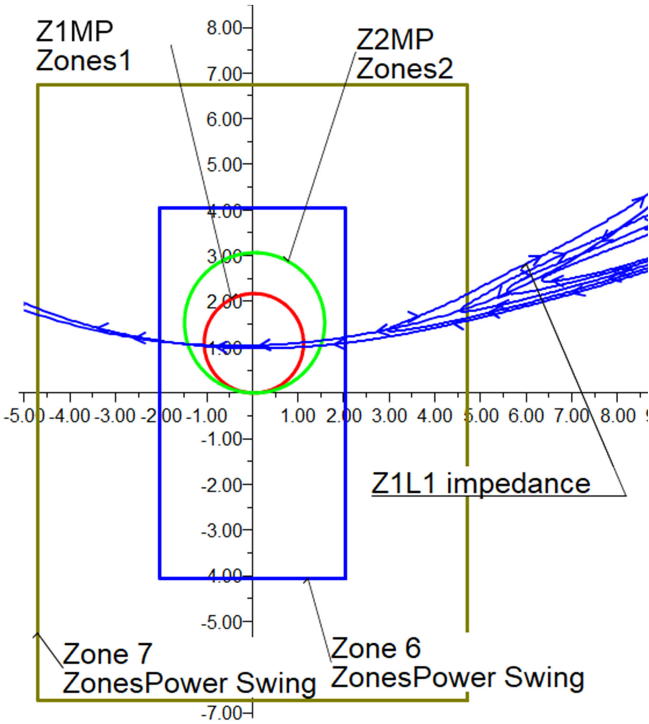
Test 1: R-X plot with OOS protection on CCT-1 line.

Figure 18.
Test 2: Rotor angle of G1 generator without OOS protection on CCT-1 line.

Figure 19.
Test 2: Rotor angle of G1 generator with OOS relay on CCT-1 line.

Figure 20.
Test 2: R-X plot without OOS relay on CCT-1 line.

Figure 21.
Test 2: R-X plot with OOS relay on CCT-1 line.

Figure 22.
Details of the location of Line-203 in the Mongolian Power System.

Figure 23.
High frequency sampling data recorded during the event of 15 September 2018.

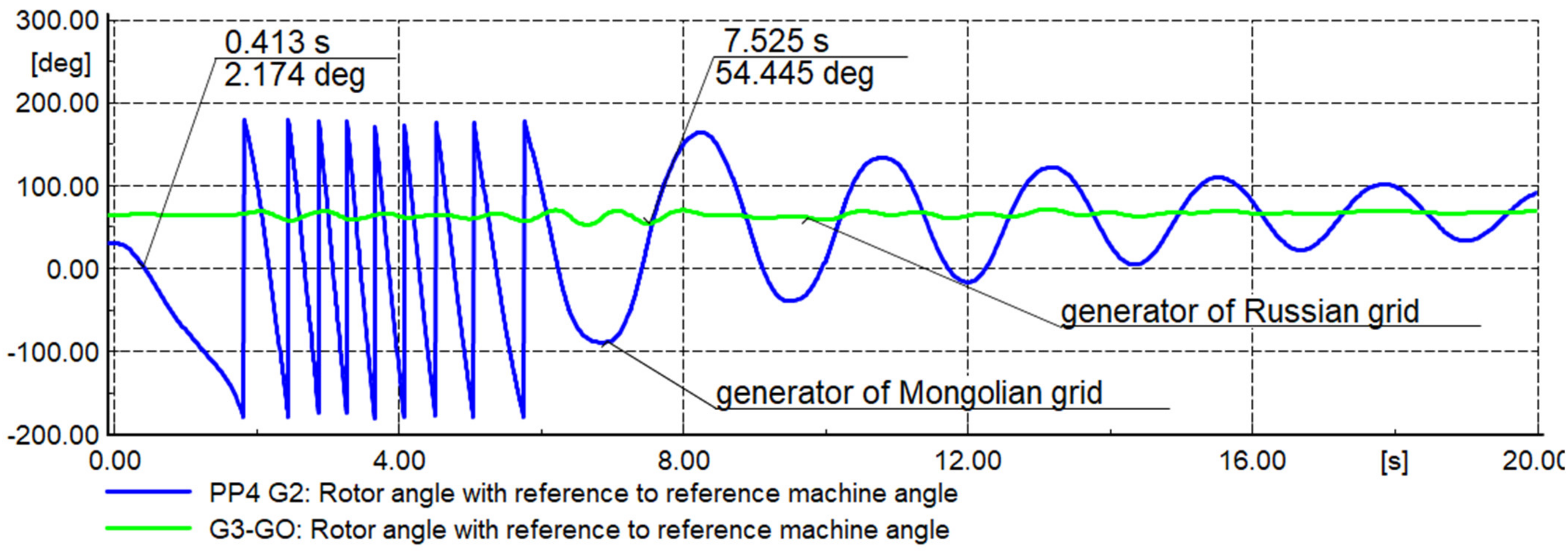
Figure 24.
Results of the rotor angle considering existing OOS protection action at Line 203.

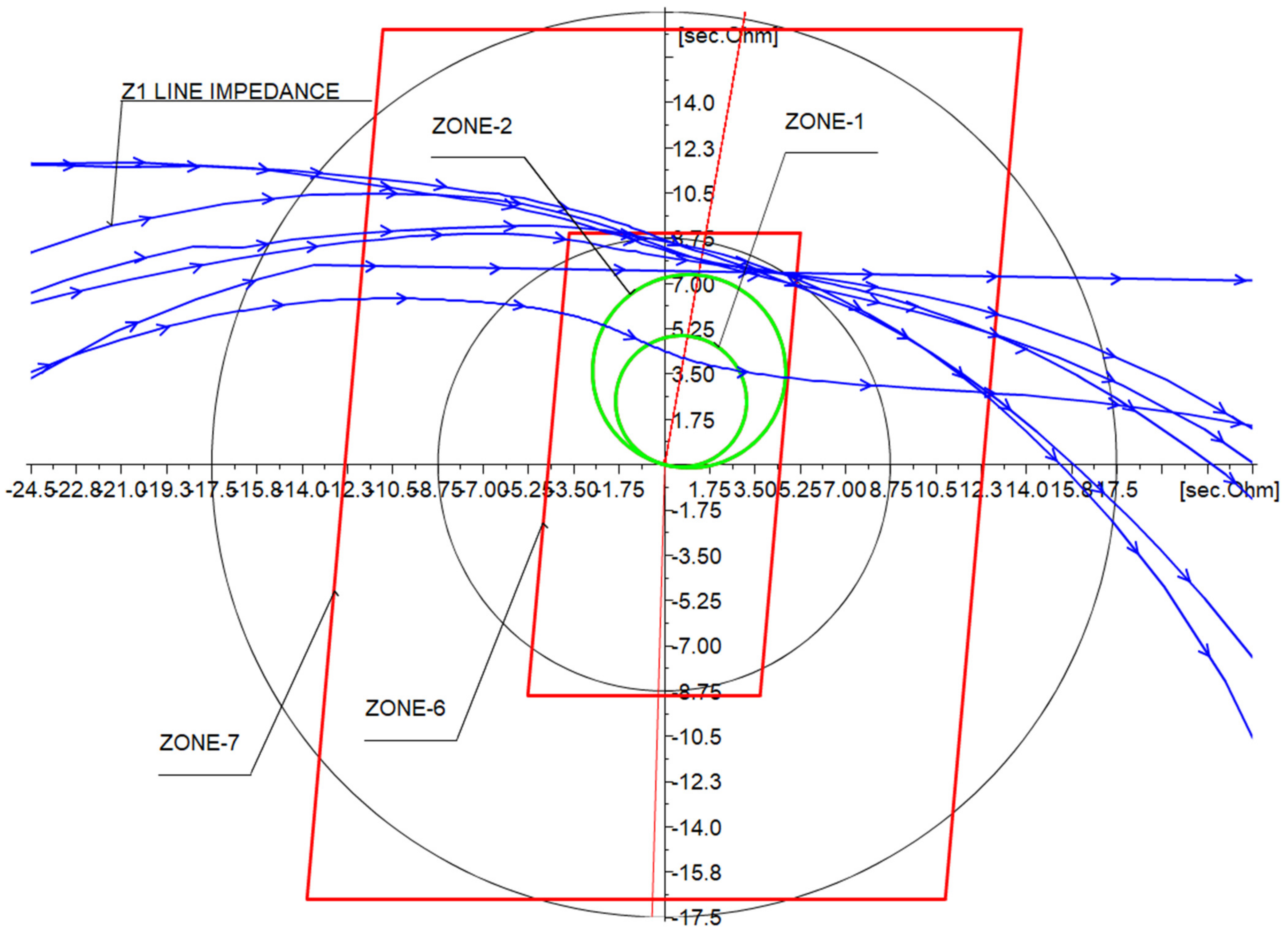
Figure 25.
Results of the power swing (R-X plane) considering the existing OOS protection installed at Line 203.
Figure 25.
Results of the power swing (R-X plane) considering the existing OOS protection installed at Line 203.

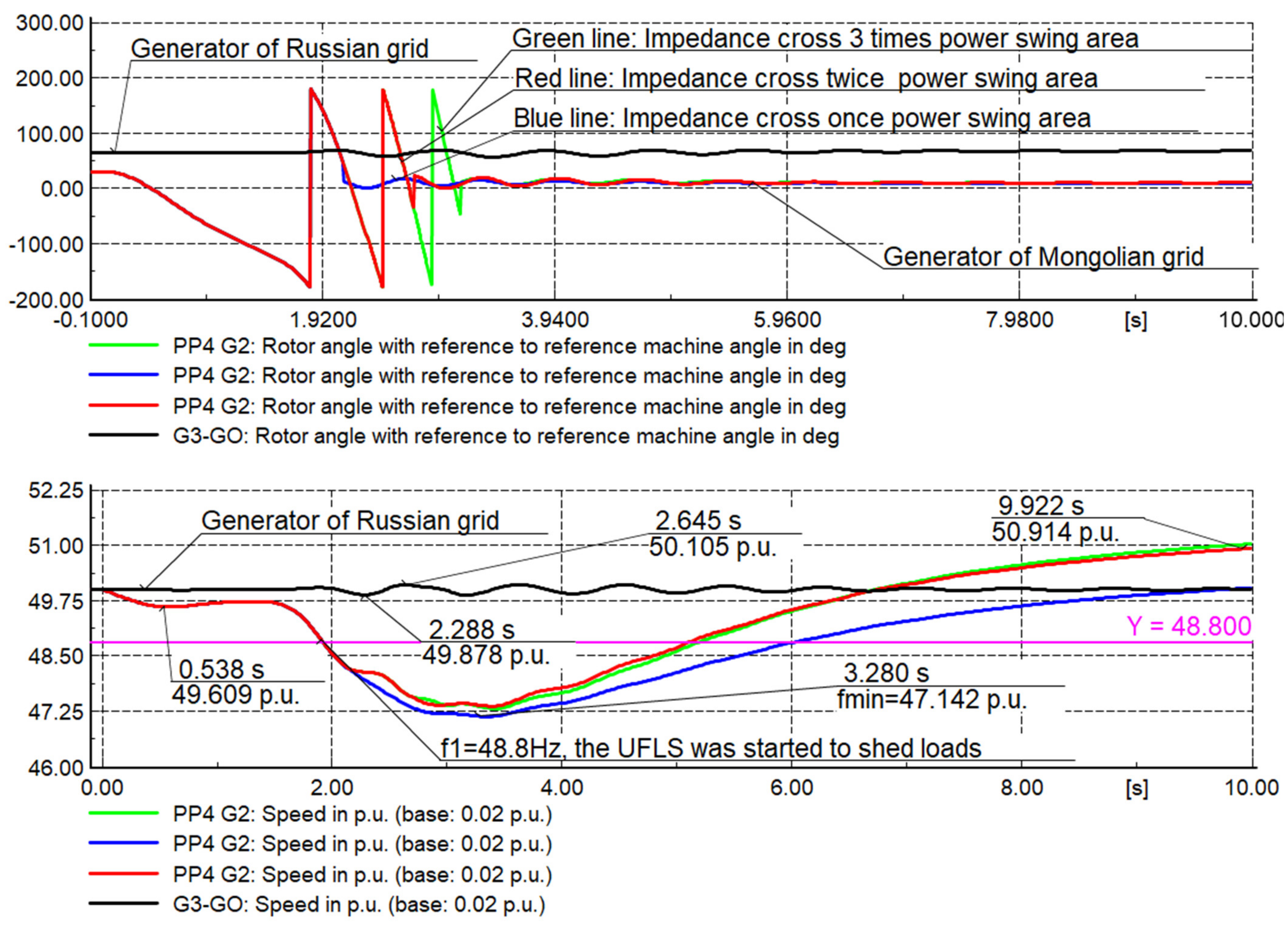
Figure 26.
Results of the rotor angle and frequency during the OOS relay impedance crosses 1, 2 and 3 times power swing area: Proposed settings.
Figure 26.
Results of the rotor angle and frequency during the OOS relay impedance crosses 1, 2 and 3 times power swing area: Proposed settings.

Figure 27.
Results of the OOS relay impedance crosses in the one, two- and three-times power swing area: Proposed settings.
Figure 27.
Results of the OOS relay impedance crosses in the one, two- and three-times power swing area: Proposed settings.

Figure 28.
Plot of the recorded time series (voltages and currents) during the event of 15 September 2018, Unstable power swing.
Figure 28.
Plot of the recorded time series (voltages and currents) during the event of 15 September 2018, Unstable power swing.

Figure 29.
General representation of the cyber-physical approach used in this paper.

Figure 30.
Results of the Cyber-physical tests: OOS proposed settings.

Figure 31.
Trajectory of positive sequence impedance in the R-X plane and OOS logic signals for Table 203 line.
Figure 31.
Trajectory of positive sequence impedance in the R-X plane and OOS logic signals for Table 203 line.


Table 1.
Two sources power system parameters.
| Parameter | Value |
|---|---|
| CCT-1, Line impedance (Z1) | (4.95∠90°) Ω |
| Zone 2 setting: Z2MP | (5.94∠88°) Ω |
| Source impedance G1 (ZS) | (3.22∠90°) Ω |
| Source Infinite bus impedances (Zr)-Infeed, Figure 11 | (3.76∠89.5°) Ω |
| CT, current transformer | 2000/5 A |
| VT, voltage transformer | 500,000/110 V |
| Nominal frequency | 50 Hz |
| CCT-1 and CCT-2, Line Length | 100 km |
| Maximum load current | 4.71 A secondary |
Table 2.
Settings of OOS protection SEL421 installed at Test System.
| Setting | Description | Entry (Secondary) |
|---|---|---|
| R1R6 | Zone-6 Resistance | 3.56 Ω |
| R1R7 | Zone-7 Resistance | 8.29 Ω |
| X1X6 | Zone-6 Reactance | 7.12 Ω |
| X1X7 | Zone-7 Reactance | 11.85 Ω |
| OSTD | OOS trip delay | 1.0 cycles |
| 50ABCP | Positive-sequency current supervision | 5A |
| 50QUBP | Negative-sequency current supervision | Off |
| OOSB (1, 2, 3) | Block zone | All zones |
| OSBD | Out-of-step block time delay | 1.5 cycles |
| EOOST | Out-of-step tripping (Yes/No) | Yes |
| OOS, No. of Crossings | Impedance cross | 1 |
Table 3.
Line-203 settings of OOS protection.
| Setting | Description | Entry (Secondary) |
|---|---|---|
| Z1L1 | 203 Line impedance | 6.04 Ω |
| R1R6 | Zone-6 Resistance | 4.48 Ω |
| R1R7 | Zone-7 Resistance | 22.34 Ω |
| X1X6 | Zone-6 Reactance | 8.96 Ω |
| X1X7 | Zone-7 Reactance | 36.83 Ω |
| OSTD | Out-of-step trip delay | 1.5 cycles |
| 50ABCP | Positive-sequency current supervision | 5 A |
| 50QUBP | Negative-sequency current supervision | Off |
| OOSB (1, 2, 3) | Block zone | All zones |
| OSBD | Out-of-step block time delay | 2.5 cycles |
| EOOST | Out-of-step tripping (Yes/No) | Yes |
| OOS, No. of Crossings | Impedance cross | 1, 2, 3 |
Publisher’s Note: MDPI stays neutral with regard to jurisdictional claims in published maps and institutional affiliations. |
© 2021 by the authors. Licensee MDPI, Basel, Switzerland. This article is an open access article distributed under the terms and conditions of the Creative Commons Attribution (CC BY) license (https://creativecommons.org/licenses/by/4.0/).
Share and Cite
MDPI and ACS Style
Gonzalez-Longatt, F.; Adiyabazar, C.; Martinez, E.V. Setting and Testing of the Out-of-Step Protection at Mongolian Transmission System. Energies 2021, 14, 8170. https://0-doi-org.brum.beds.ac.uk/10.3390/en14238170
AMA Style
Gonzalez-Longatt F, Adiyabazar C, Martinez EV. Setting and Testing of the Out-of-Step Protection at Mongolian Transmission System. Energies. 2021; 14(23):8170. https://0-doi-org.brum.beds.ac.uk/10.3390/en14238170
Chicago/Turabian StyleGonzalez-Longatt, Francisco, Choidorj Adiyabazar, and Ernesto Vazquez Martinez. 2021. "Setting and Testing of the Out-of-Step Protection at Mongolian Transmission System" Energies 14, no. 23: 8170. https://0-doi-org.brum.beds.ac.uk/10.3390/en14238170
Note that from the first issue of 2016, this journal uses article numbers instead of page numbers. See further details here.