Article

SOC Based Battery Cell Balancing with a Novel Topology and Reduced Component Count

1
School of Mechanical Engineering, Xi'an Jiaotong University, Xi'an, Shaanxi 710049, China
2
Department of Electrical and Computer Engineering, University of Michigan, Dearborn, MI 48128, USA
*
Author to whom correspondence should be addressed.
Energies 2013, 6(6), 2726-2740; https://0-doi-org.brum.beds.ac.uk/10.3390/en6062726
Submission received: 7 April 2013 / Revised: 26 April 2013 / Accepted: 16 May 2013 / Published: 24 May 2013

Abstract

:
This paper proposes a novel battery cell balancing topology with reduced component count and simplified control. The balancing algorithm is based on the state of charge (SOC) of each individual cell instead of cell voltage. The principle of the proposed topology is analyzed and verified through simulation and experiments. Then an experimental battery test workbench is established to validate the proposed balancing algorithm. The experimental results show that the proposed balancing topology and associated algorithm can perform well in real applications.

1. Introduction

Battery technology has attracted more and more attention due to the development of green energy applications such as electric vehicles (EVs) and smart grids [1,2]. However, the voltage of a single battery cell is inherently low. In actual applications, such as EVs and utility energy storage in smart grids, the voltage of the battery pack is designed to be hundreds to thousands of Volts to optimize the system performance. Battery strings with a large number of battery cells connected in series are necessary in such applications.
The differences in cell internal resistance, nominal capacity, degradation level and ambient temperature would be inevitable among the many cells in a battery string, which would lead to state of charge (SOC) imbalance in the battery cells. Such an imbalance in the battery string could cause many problems. The available capacity of the battery string would dramatically decrease due to “Bucket Effects” in the battery string. The imbalance can potentially cause overcharge and/or overdischarge situations, which are dangerous for batteries, especially for lithium-ion (Li-ion) batteries. Therefore, to maintain the performance and enhance the cycle life, battery cell balancing is of paramount importance in real applications.
Many balancing schemes and circuits have been presented in previous studies [3,4,5,6,7,8,9,10,11,12,13,14,15,16]. These methods could be categorized as the passive and the active balancing methods. The passive balancing methods [17,18,19] would remove the excess energy from high energy cell(s) through resistors until the state of the battery matches those of the low energy cells in the battery string. The problem is that the energy is dissipated through resistors as heat, increasing the difficulty of thermal control of the battery pack and decreasing the efficiency of the battery system. Meanwhile, the balancing process only works on the high energy battery cells. If most of the battery cells have higher energy than some other cells, a large amount of energy would be wasted.
The active balancing methods utilize active switching circuits to transfer energy between cells or between the cell(s) and the battery string. Very little energy would be wasted in this case compared to the passive balancing methods. However, more switches and associated components are needed to fulfill the functions. These additional components would lead to increased cost and reliability concerns. To make active balancing more competitive, the cost and reliability should be carefully considered, including but not limited to simplifying the structure of the topology, reducing the number of components, and reducing the control complexity. Such aspects are carefully considered in this paper to improve the balancing performance and reduce the cost of implementing an active balancing method.
On the other hand, voltage-based balancing strategies are widely used in battery cell balancing. However, due to the flatness of open circuit voltage (OCV) versus SOC (the OCV-SOC curve is flat at the intermediate SOC sections for most Li-ion batteries), voltage-based balancing methods cannot perform well in such intermediate SOC sections. The balancing process would only work effectively at the low SOC section or the high SOC section, where the OCV-SOC curve is much steeper. To assure that the cells are balanced, the balancing capacity needs to be designed much bigger, leading to a higher cost. Unfortunately, in order to preserve the life of the battery and avoid overcharge or overdischarge, such low or high SOC sections are not often used in hybrid electric vehicles (HEVs), which in turn cause many active balancing methods inefficacious.
An alternative to the voltage based balancing is the SOC-based balancing. As one of the key parameters of a battery, SOC estimation methods have been widely studied [20,21,22,23,24]. If the accurate SOC of each cell could be obtained, the balancing processes could be carried out at any time when there is a difference in cell SOC. Therefore, a SOC-based balancing algorithm is proposed in this paper in conjunction with the proposed balancing topology.

2. The Proposed Balancing Topology

Many balancing topologies have been studied recently [3,4,5,6,7,8,9,10,11,12,13,14,15,16]. Several popular balancing topologies are described and analyzed in this section. Based on the analysis of these existing balancing topologies, a novel balancing topology with a simpler structure and reduced component count is then proposed.

2.1. Analysis of the Existing Balancing Topologies

A bidirectional buck-boost converter based balancing topology [9,10,11], which is referred to as Topology 1, is shown in Figure 1a. In this method, the energy is transferred from a high energy cell to its adjacent cell through a buck-boost converter. However, cells can only be balanced by their adjacent cells. If the two cells that need to be balanced are separated by a long distance (C1 and Cn for instance), it would take more than one step to balance them and it will also need a longer time to transfer energy between these two cells.
Figure 1. Several existing active balancing topologies: (a) Bidirectional buck-boost convertor balancing topology; (b) Traditional bidirectional flyback converter balancing topology; (c) Shared transformer flyback converter balancing topology.
Energies 06 02726 g001
Figure 1b shows another one of the widely used balancing topologies [12,13], which is referred to as Topology 2. In this topology, a bidirectional flyback converter is connected to each cell. The secondary winding of the transformer is connected to the battery string terminals. This method transfers energy between a cell and the battery string. Due to the large number of separate converters, cells could be balanced with the battery string simultaneously. Although it is a string to cell balancing method, the total balancing time could be dramatically reduced comparing to Topology 1. However, 2n switches and 2n windings are needed for a battery string with n cells. Since the secondary winding of the transformer is connected to the battery string terminals directly, the switches in the secondary winding of the transformer would suffer high voltage stress. The turns-ratio of the transformer is very large, due to large voltage difference between cells and the battery string. All these aspects would lead to high cost. Meanwhile, the converter efficiency would be relatively low due to the high turns-ratio of the transformer.
Figure 1c depicts another widely used balancing topology [10,14,15,16], which is referred to as Topology 3. In this topology, only one multi-winding transformer is utilized. The transformer has n primary windings connecting to n battery cells, respectively, and one secondary winding connecting to the battery string terminals. Comparing this topology to Topology 2, it is clear that this topology combines n separate converters to a single converter. In this way, the switches are reduced to n + 1, nearly half the number of switches used in Topology 2. Furthermore, only one switch in this topology would suffer high voltage stress. The secondary windings connecting to the battery string terminals are also reduced to one from n. The cost of this topology would be dramatically reduced compared to Topology 2. However, in this topology, only one cell could be balanced at a time and it is still a string to cell balancing method, leading to a longer balancing time comparing to Topology 2. Besides, the transformer turns-ratios are the same as those of Topology 2, and the converter efficiency would be almost the same as that of Topology 2.

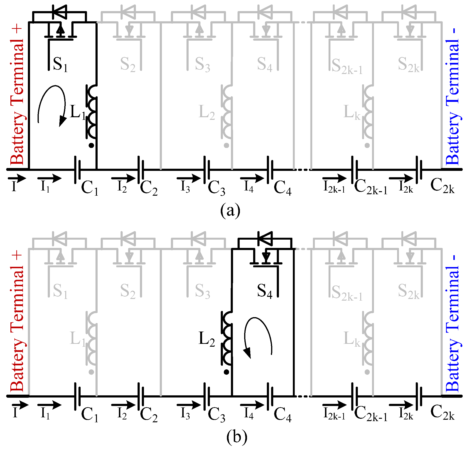
2.2. The Proposed Balancing Topology

Based on the analysis of the three popular balancing topologies discussed above, a new balancing topology is proposed as shown in Figure 2. The novel balancing topology will reduce the number of switches, the number of windings, and also the cost, but retain full balancing functions with high reliability due to its reduced component count. Meanwhile, the control signal will be much simpler, leading to a much simpler control and gate drive system. The cell to cell balancing method is realized, leading to a reduction of balancing time and complexity of the control processes. Furthermore, the transformer turns-ratios are low for the cell to cell balancing method, leading to a relatively higher balancing efficiency and small transformer size.
Figure 2. The proposed bidirectional flyback converter balancing structure.
Energies 06 02726 g002
In Figure 2, L1, L2 to Lk are coupled windings, and every two cells in the string share one of such windings. For example, C1 and C2 share the same winding L1. Current I is the main current applied to the battery string, while I1, I2, …, and I2k are the balancing current for each cell, respectively. To ensure every two cells sharing a winding, the total number of cells (n) in the battery string are designed to be even (n = 2k, k =1, 2 …).
In this topology, the two adjacent cells which share one winding (C1 and C2 for instance), would form a buck-boost converter similar to that of Topology 1. Meanwhile, due to the coupled windings, nonadjacent cells (C1 and C4 for instance) and its windings would form flyback converters, so energy could easily be transferred from one cell to another cell according to the principles of a buck-boost converter and a flyback converter. The cell to cell balancing method is realized with a time-saving balancing process. The components needed for a battery string with n cells are compared in Table 1 for the proposed topology and the existing topology.
Table 1. A comparison of component count.
ItemTopology 1Topology 2Topology 3The proposed topology
Windingsn − 12nn + 1n/2
Ferrite cores0n11
Switches2n − 22nn + 1n
Number of switches suffering high voltage stress0n10
Balancing typeBetween adjacent cellsBetween cell and stringBetween cell and stringBetween arbitrary cells
As shown in Table 1, only one switch and one winding are needed for each cell for the proposed topology. None of the switches used in the proposed topology have high voltage stress issues, therefore, the cost of such a balancing topology would be dramatically reduced. The balancing current will be proportional to the cell voltage and can be controlled by controlling the duty ratio of the gate signal using a pulse-width-modulated (PWM) waveform.
However, due to the shared windings in the proposed structure, energy could not be transferred between the same parity number cells. For example, energy could not be transferred between C1 and C3 directly, but two steps should be carried out to balance such two cells. Energy could be transferred from C1to C2 firstly, and then from C2 to C3. Details are discussed in Section 3.
In Figure 3 and Figure 4, the operation procedures of the proposed topology are depicted. Since all the windings in the proposed balancing topology are coupled, a typical situation is considered to explain the main principle of the balancing topology. Neglecting the losses, the circuits of the topology are controlled such that energy is transferred from C1 to C4. Other situations could also be explained by one or two of such processes. To simplify the gate drive circuits of the switches, P-Channel MOSFETs are selected for the odd number cells and N-Channel MOSFETs for even number cells.
A cycle of the operation starts when S1 is turned on to conduct winding L1 and C1, as shown in Figure 3a. Since S1 is a P-Channel MOSFET, the gate drive voltage VGS1 is negative to turn S1 on, as shown in Figure 4. The inductance of winding L1 and voltage of C1 would lead to the process as follows:
V L 1 = L 1 d I 1 d t
where V L 1 is the voltage of winding L1.
Since S1 is conducting during this time interval, the voltage of L1 and C1 should be the same:
V L 1 = V C 1
where V C 1 is the voltage of C1.
For a certain time t (t0 < t < t1), current I1(t) could be expressed as follows:
I 1 ( t ) = t 0 t V C 1 L 1 d t = V C 1 L 1 ( t t 0 )
Since V C 1 can be considered constant during this time interval, I1(t) has a constant slope from t0 to t1, as shown in Figure 4.
At t1, S1 is turned off, and a time interval Td1 between t1 and t2 is used as the dead-time to avoid the two switches being switched on at the same time.
At t2, S4 is turned on. At this point, the voltage of L2 and C4 should be the same:
V L 2 = V C 4
Since all the windings are coupled, the current of the two coupled windings should be almost the same as the transformer has a turns-ratio of 1:
I4I1
According to the following relationship:
V L 2 = L 2 d I 4 d t
Considering the initial situation of the current, I4 could be written as:
I 4 ( t ) = I 4 ( t 2 ) t 2 t V 4 L 2 d t V 1 L 1 ( t 1 t 0 ) V 4 L 2 ( t t 2 )
At t3, all the switches are turned off. A time interval Td2 between t3 and t4 is inserted to ensure the formed flyback converter is operated in discontinues mode. Because energy could only be transferred between an even cell and an odd cell due to the balancing structure proposed in this paper, if the two cells are in the same group, then two steps are needed to finish the balancing procedure.
Figure 3. Operational modes of the proposed bidirectional flyback converter balancing structure: (a) Step one (t0 − t1); (b) Step two (t2 − t3).
Energies 06 02726 g003
Figure 4. Key waveforms of the proposed bidirectional flyback converter balancing structure.
Energies 06 02726 g004

3. Analysis of SOC Based Balancing Algorithm

Although the above analysis is based on the cell voltage, the actual balancing of the cells could be based on the cell voltage difference or cell SOC. The proposed method is capable of voltage- and SOC-based balancing.

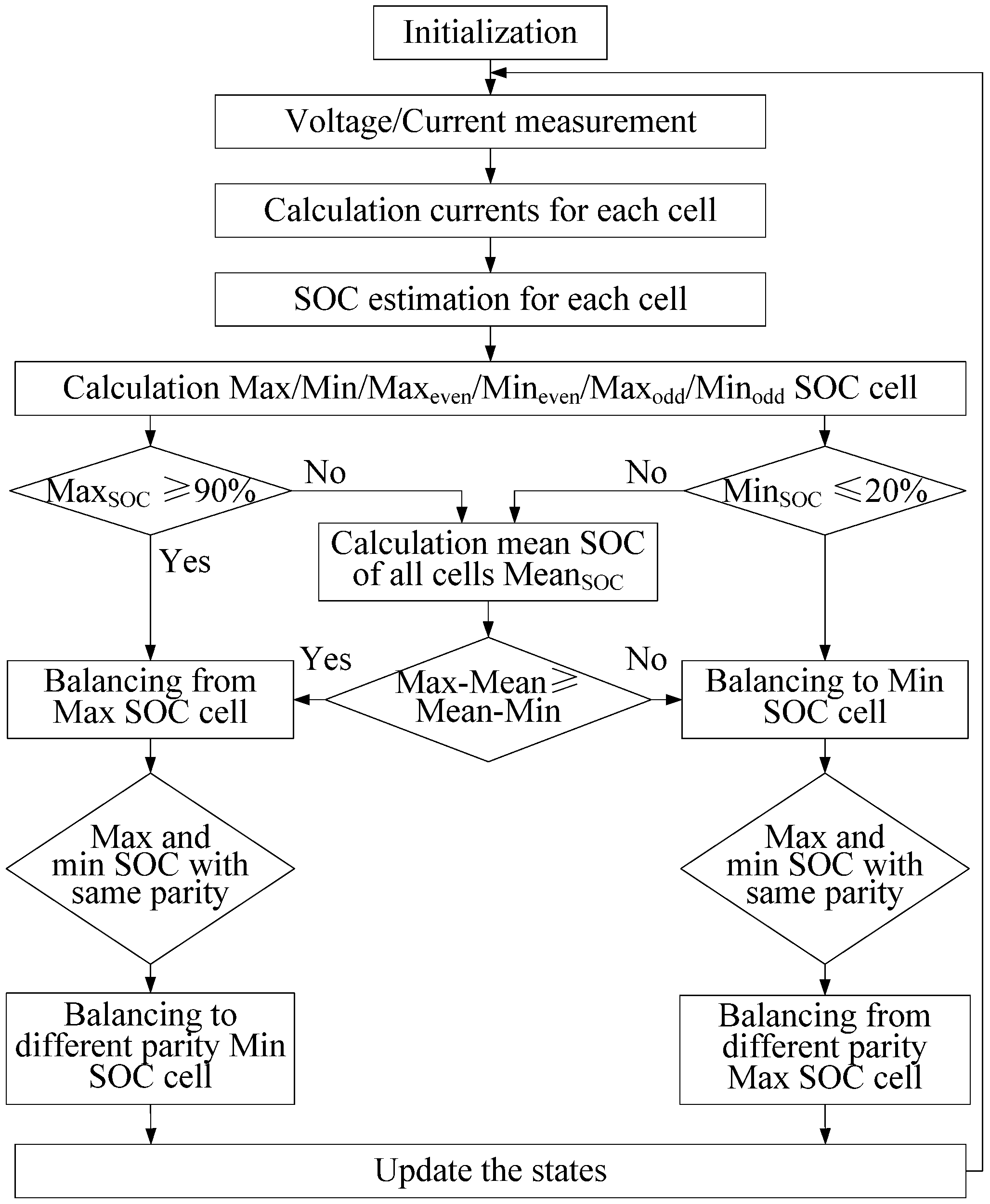
3.1. SOC Based Balancing Strategy

As discussed in Section 1, voltage-based balancing is not very effective in the middle section of SOC due to the flat OCV-SOC curves. Therefore, this paper introduces the SOC-based balancing to enhance balance effectiveness and reduce balance time. The definition of SOC of a battery is the ratio of the remaining capacity to the nominal capacity of the battery, which can be described as:
SOC = (Remaining Capacity)/(Norminal Capacity)
If the SOC of each cell could be obtained, SOC based balancing algorithms could be executed to achieve better balancing performance with the proposed topology and ensure that the balance could be realized in the whole SOC range.
With the existing balancing technology, typically, the energy is balanced from the highest energy cell to the lowest energy cell, but in this paper, a balancing priority is utilized to determine which cell has to be balanced first. The flowchart of this balancing strategy is shown in Figure 5.
Figure 5. Flowchart of SOC-based balancing strategy.
Energies 06 02726 g005
If the maximum SOC in the battery string is larger than a certain value, 90% for instance, the battery string is considered to be near full charge state. To avoid overcharge of the battery string, the maximum SOC cell should be discharged first, and this cell is marked as the highest balancing priority cell. Similarly, if the minimum SOC in the battery string is less than a certain value, 20% for instance, to avoid overdischarge, this minimum SOC cell has the highest balancing priority.
If the battery string is in neither of these two cases, it is considered as the normal state. In the normal state, the mean SOC of the battery string is calculated first. Both the maximum and the minimum cell SOC are compared with the mean SOC to get the difference from the mean SOC. If the difference between the maximum SOC and the mean SOC is bigger than that between the minimum SOC and the mean SOC, the maximum SOC cell has the highest balancing priority. Otherwise, the minimum SOC cell has the highest balancing priority.
By the procedure described above, the highest balancing priority cell is selected. The next step is to select the other cell needed to be balanced. Due to the unique structure of the proposed balancing topology, the two cells needed to be balanced should be in the different groups, so, after the highest balancing priority cell is selected, the next cell needing balancing is selected in the other group. For example, if the highest balancing priority cell is the maximum SOC cell and is in the even group, than the other cell is selected from the minimum SOC cell in the odd group (Minodd).

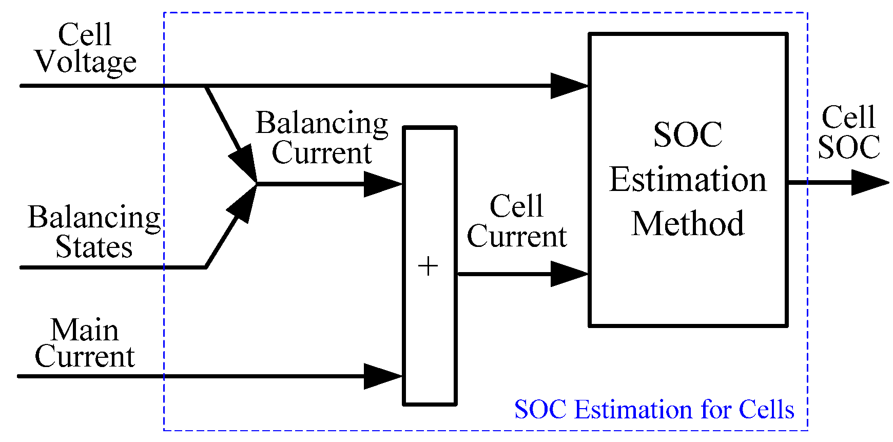
3.2. Cell SOC Estimation Method

Many SOC estimation methods have been studied in previous works [20,21,22,23,24]. Considering the real-time implementation issue, the computational complexity of the SOC estimation of the cells in the battery string should be carefully considered. For a battery string with n cells, the SOC estimation has to be carried out n times in each sample time, which requires a simple SOC estimation method with small estimation errors. An accurate SOC estimation method with lower computation complexity should be considered. In this paper, the PI observer-based SOC estimation method is introduced, which was proposed by the authors in their previous work [24]. Nevertheless, if further studies about SOC estimation for each cell in a battery pack were developed in the future, such SOC estimation methods could also be added to the strategy studied in this paper to improve the balancing performance.
Since there is no current sensor for each cell in the balancing circuit, the balancing current should be first estimated in order to estimate the SOC of each cell. According to the characteristics of the balancing circuit and the analysis in Section 2, the balancing current is treated as proportional to the voltage of the cell. The coefficients can be obtained from experiments by the least squares method. The procedure of the estimation of the cells in the battery string is depicted in Figure 6.
Figure 6. SOC estimation for the cells in the battery string.
Energies 06 02726 g006
In this procedure, the balancing states, including cells to be balanced, are selected as the estimation input. According to the assumption stated above, the balancing current could be calculated. The balancing current of the cell is added to the main current measured by the current sensor to obtain the actual cell current. This actual cell current and the measured cell voltage are sent to the SOC estimation method to calculate the SOC of each cell.

3.3. Discussions

The nominal capacity of the cells in the string is assumed to be the same in this study. In real applications, if the cells are always under balanced states with the help of balancing processes, the capacities would vary very little during normal operations. Furthermore, in applications such as EVs, the battery packs are under strict thermal control, so the temperature of the battery pack will have minimal impact on the cell capacity in the string, so the method in this paper would be sufficient in such applications. However, capacity variation may happen in certain circumstances. The impacts of cell capacity on the balancing strategy would be studied in our future work.

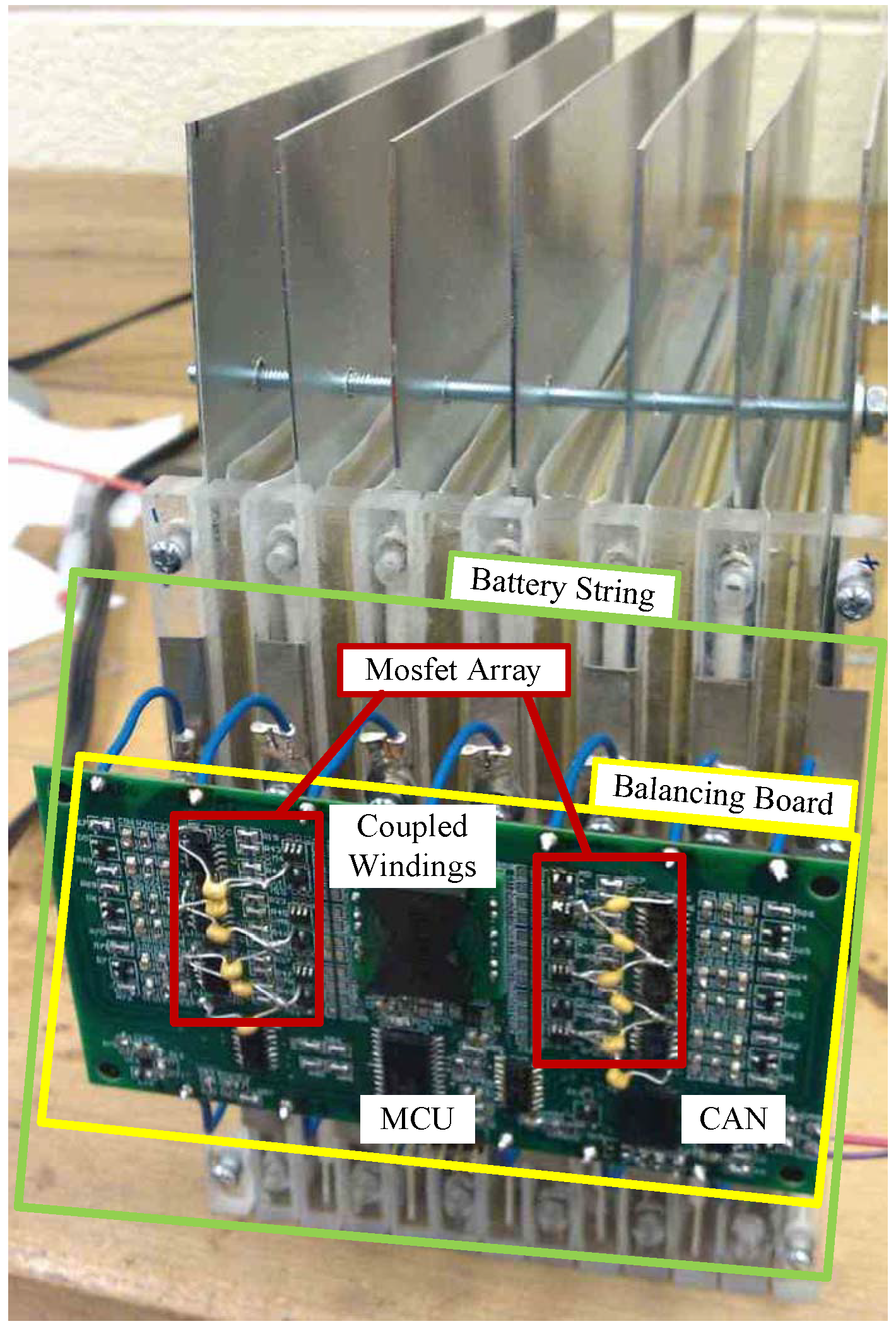
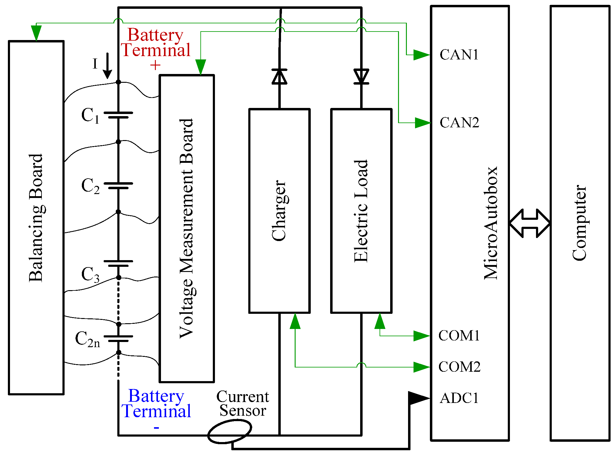
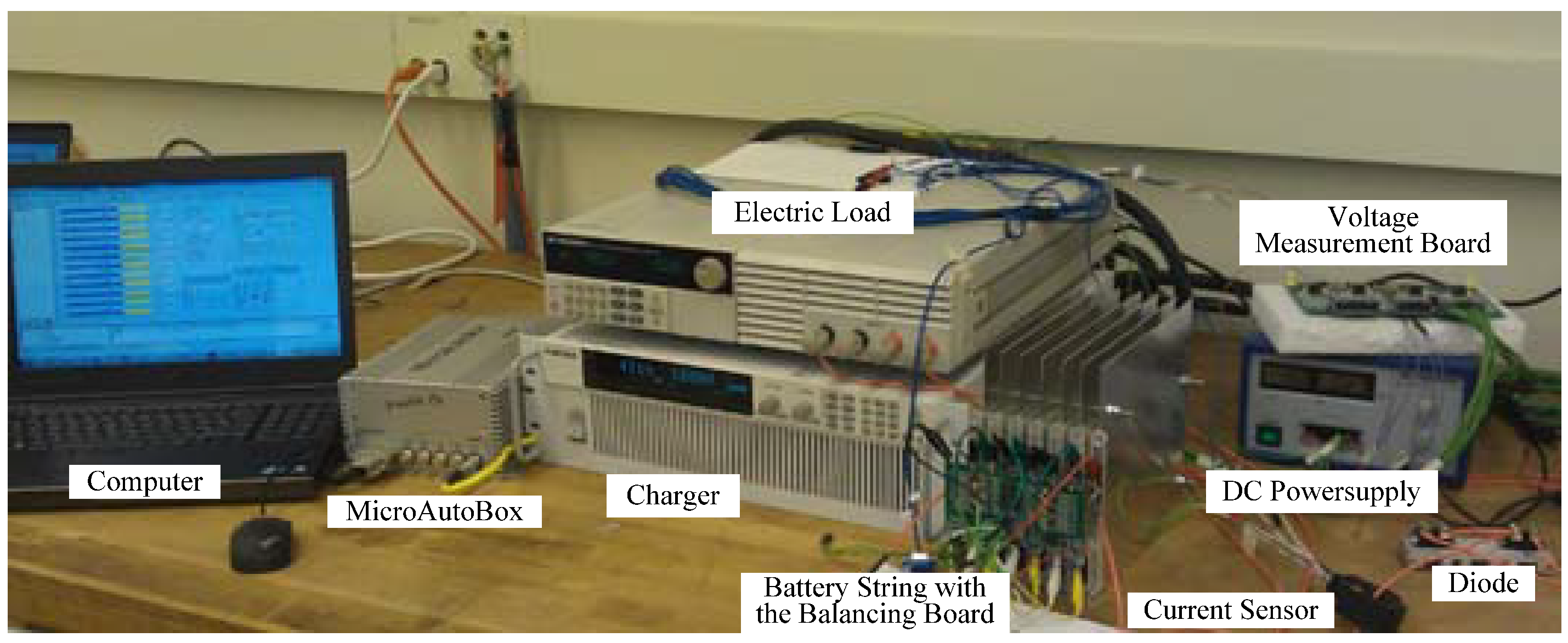
4. Experiments and Validation

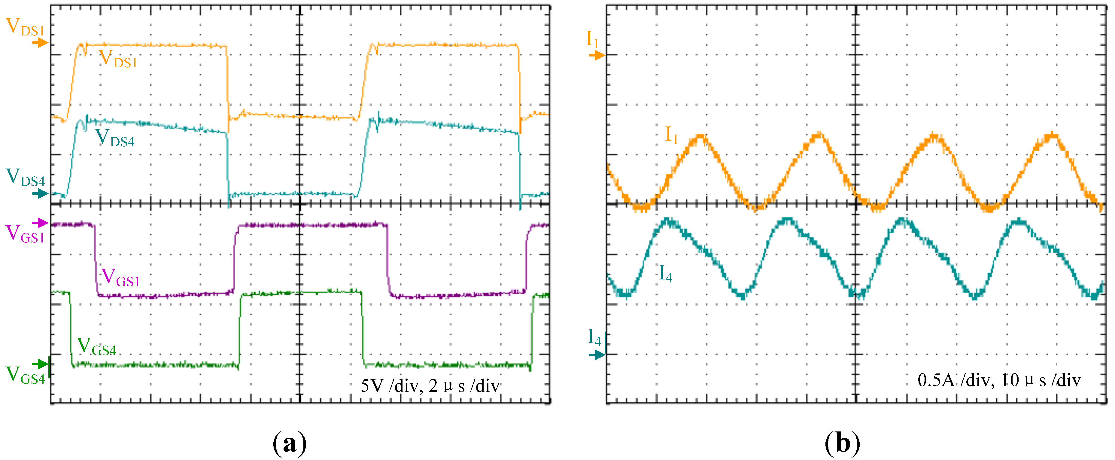
4.1. Circuit Simulation and Experimental Verification

To verify the functions of the proposed balancing topology, the circuits was designed and fabricated. The balancing board is connected to the battery string as shown in Figure 7.
Figure 7. Designed circuit for the proposed balancing topology.
Energies 06 02726 g007
The command signals are sent to this balancing board through a CAN connector to decide which cells should be balanced. After receiving the CAN command, the balancing board works with the procedures stated in Section 2. The control sequences to fulfill the balancing processes are written in C code and downloaded to the balancing board. Some key waveforms of the balancing processes are measured and shown in Figure 8.
Figure 8. The waveforms of the designed circuit for the proposed balancing topology: (a) The GSV and DSV of the MOSFETS. (b) The balancing currents of the two cells.
Energies 06 02726 g008
In Figure 8, VGS1 is the Gate to Source voltage (GSV) of S1, and VDS1 is the Drain to Source voltage (DSV) of S1. The denotations for S4 are in the same manner. When S1 is turned on, GSV is zero. At this time, S4 is off, so DSV of S4 is maximum. When S1 is off and S4 is on, VDS1 comes to the negative maximum while VDS4 is zero. At the end of one balancing process, both S1 and S4 are off for a time interval Td2 to assure the converter is operating at discontinues mode. Figure 8b shows the balancing currents of the two cells. The balancing current of C1 is negative, indicating the energy is drawn from this cell. The balancing current of C4 is positive, indicating the energy is transferred to this cell. A LC filter is utilized to reduce the ripple of the balancing current, so the balancing current is slightly different from that discussed in section II. The performance shown in Figure 8b proves the full functions of the circuits and the balancing abilities of the proposed balancing topology.

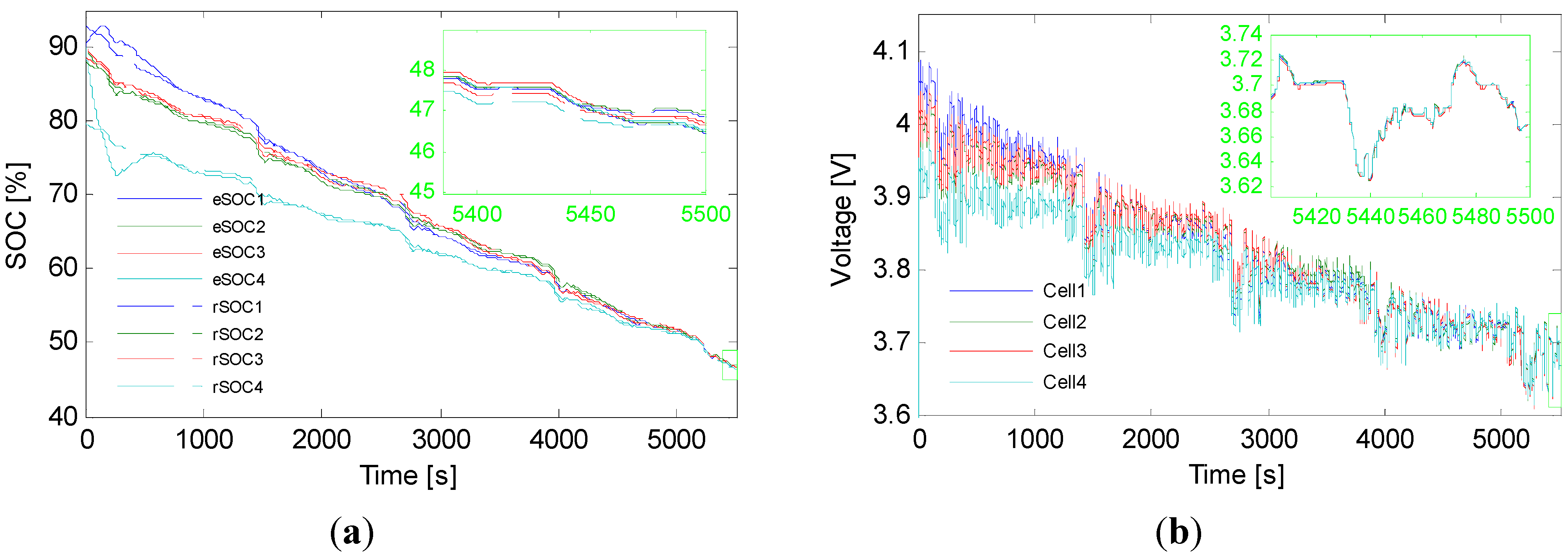
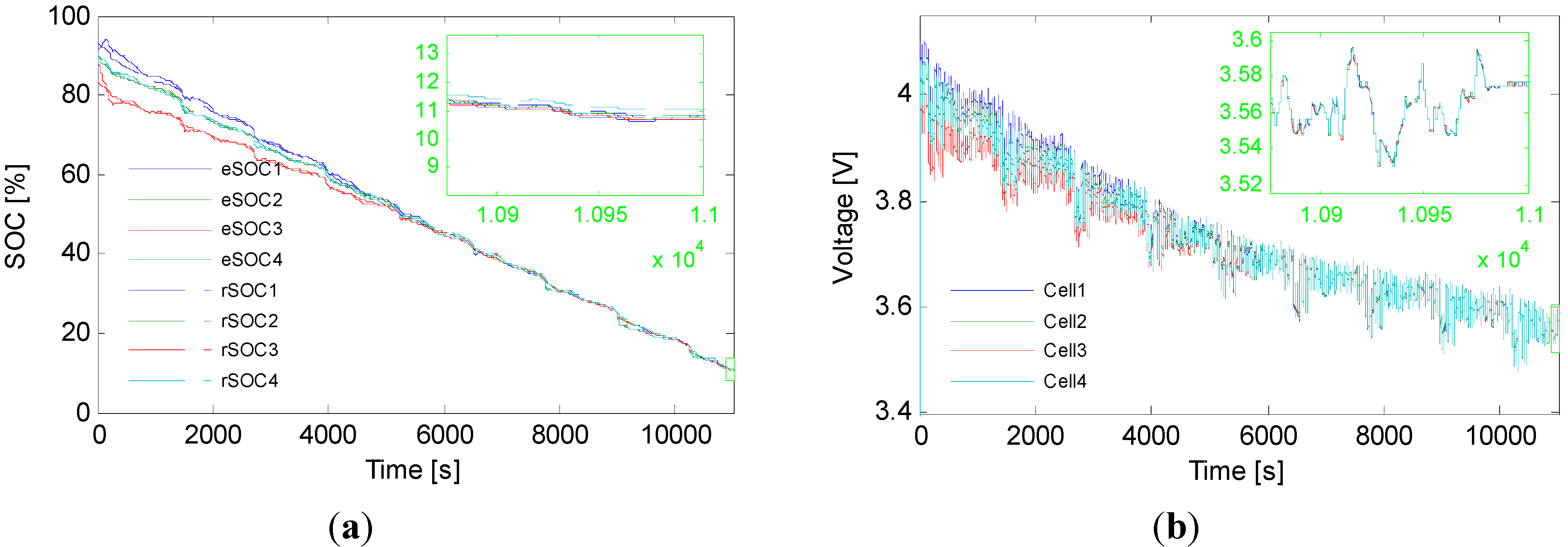
4.2. Validation of the Proposed SOC Based Balancing Strategy

To validate the performance of the balancing topology and the SOC based balancing strategy, an experimental battery test bench is established. The structure of the bench is depicted in Figure 9. In this workbench, the balancing board is connected to a Li-ion battery string, which includes 12 cells connected in series. A voltage measurement board is also connected to the battery string to measure the voltage of each cell in the battery string. A charger and an electronic load are connected in parallel to the terminals of the battery string through a diode respectively. A Hall current sensor is utilized to measure the main current of the battery string. The balancing board, the voltage measurement board are controlled by the MicroAutobox through CAN signals. The charger and the electric load are controlled by the MicroAutobox through RS232 signals. The picture of the workbench is shown in Figure 10.
Figure 9. The structure of the experimental battery test workbench.
Energies 06 02726 g009
Figure 10. The Experimental Battery Test Workbench.
Energies 06 02726 g010
The MicroAutobox is controlled by a computer to simulate some current profiles applied to the battery string. The current profiles are sent out by CAN signals to the charger and the electronic load, and finally applied to the battery string. These profiles include constant current charge, constant voltage charge, constant current discharge and drive cycles, such as Urban Dynamometer Driving Schedule (UDDS), Highway Fuel Economy Test (HWFET), etc. The MicroAutobox is also used to perform the SOC estimation of each cell in the battery string and select the cells to be balanced. Firstly, the MicroAutobox obtains the cell voltages from the voltage measurement board through CAN signals and also the main current of the battery string through an analog to digital converter (ADC). The information are combined in the MicroAutobox and applied to the PI observer SOC estimation method. The SOC of each cell are obtained at each sample time. Secondly, these obtained SOC are carefully calculated to get the key information as needed, such as the maximum SOC and minimum SOC. Then, the SOC based balancing strategy is implemented. Such decisions are sent out by CAN signals to the balancing board which performs the balancing processes as required.
To fully consider the various situations in real applications, the widely used UDDS current profile is applied to the battery string to simulate the drive cycles of a HEV. The current counting method is utilized to calculate the reference SOC.
In the first case, the initial SOC is set to be 93%, 88%, 88% and 80% for the four cells respectively. This is the same situation as stated in Section 2, in which the energy is balanced from C1 to C4 at the beginning of the process. Several UDDS current profiles are applied to the battery string. During this simulated driving conditions, the balancing processes are performed according to the proposed SOC based balancing strategy. The results are shown in Figure 11. The reference SOC is referred to as rSOC and the estimated SOC as eSOC in the figure.
The actual initial SOC of the four cells are different, while these actual SOCs are not known to the SOC estimator. Initially, the balance algorithm assumes that the initial SOC are the same at 90% for all four cells, which means no balance is needed. However, after a few sampling cycles (about 50 to 100 seconds), the true SOC of each cell is estimated and the difference is now seen by the balancing algorithm. It is obvious that the estimated SOC converge to the reference SOC quickly with the PI based SOC estimation method. With the estimated cell SOC, the SOC-based balancing algorithm starts as shown in the figure. Eventually, the cells are balanced in 4,000 seconds.
As depicted in Figure 11, the initial SOC of the four cells are different, with the differences being larger than 10%. With the operation of the balancing procedures, as shown in Figure 11 a, the SOC of C4 and C1 converge to the SOC of other two cells, and finally the SOC of the four cells are almost the same. The voltage results of the balancing processes are given in Figure 11b. The voltages of the four cells converge to almost the same at the end of the experiment as shown in Figure 11b, which is another proof of the effectiveness of the balancing processes.
In the second case, the initial SOC is set to be 93%, 88%, 83% and 88%, respectively. This is a special situation in which the energy could not be transferred from C1 to C3 directly because they are with the same parity number. The SOC based strategy stated in Section 3 is utilized to decide the balancing processes. The results are shown in Figure 12. From the SOC curves in Figure 12a, it is obvious that the balancing results are satisfactory, and all the four cells come to the same SOC at about 40% SOC. The voltages of the cells are also mostly overlapping at this point as shown in Figure 12 b.
Figure 11. The Results of the experiment in situation 1: (a) SOC balancing results; (b) Voltage results.
Energies 06 02726 g011
Figure 12. The Results of the experiment in situation 2: (a) SOC balancing results; (b) Voltage results.
Energies 06 02726 g012
To further illustrate the performance of the SOC estimation method and the balancing strategy, the UDDS drive cycles continue to be applied to the battery string and the balancing process continues to be carried out. As shown in Figure 12, the SOC of the four cells are almost the same after the 40% SOC point, indicating that the cells could be kept balanced. The voltage responses in Figure 12b overlap after 40% SOC, which also proves that the cells are balanced.

4. Conclusions

This paper proposed a simple battery balancing topology in which only one switch and one winding are needed for each cell. The topology can realize cell-to-cell balancing function with a either voltage-based or SOC-based balancing strategy. The balancing circuits of the topology was designed and fabricated. The measured waveforms verified the balancing functions of the balancing topology. The experimental battery balancing workbench was established to validate the SOC-based balancing strategy. The results showed that even if the initial states of the cells in the battery string are different, the SOC converges to almost the same value after a short period of time with the balancing activated. Meanwhile, the voltage of the cells also converges to the same value, further indicating the satisfactory performance of the proposed SOC-based balancing strategy.

Acknowledgments

The work was partly supported by the DOE/Chrysler under grant DE-EE0002720 and the China Scholarship Council (CSC).

References

  1. Baker, E.; Chon, H.; Keisler, J. Battery technology for electric and hybrid vehicles: Expert views about prospects for advancement. Technol. Forecast. Soc. Chang. 2010, 77, 1139–1146. [Google Scholar]
  2. Divya, K.C.; Østergaard, J. Battery energy storage technology for power systems—An overview. Electr. Power Syst. Res. 2009, 79, 511–520. [Google Scholar] [CrossRef]
  3. Lee, Y.S.; Cheng, M.W. Intelligent control battery equalization for series connected lithium-ion battery strings. IEEE Trans. Ind. Electron. 2005, 52, 1297–1307. [Google Scholar] [CrossRef]
  4. Lee, Y.S.; Cheng, G.T. Quasi-resonant zero-current-switching bidirectional converter for battery equalization applications. IEEE Trans. Power Electron. 2006, 21, 1213–1224. [Google Scholar] [CrossRef]
  5. Tolbert, L.A.; Peng, F.Z.; Cunnyngham, T.; Chiasson, J.N. Charge balance control schemes for cascade multilevel converter in hybrid electric vehicles. IEEE Trans. Ind. Electron 2002, 49, 1058–1064. [Google Scholar] [CrossRef]
  6. Maharjan, L.; Inoue, S.; Akagi, H.; Asakura, J. State-of-charge (soc)-balancing control of a battery energy storage system based on a cascade PWM converter. IEEE Trans. Power Electron. 2009, 24, 1628–1636. [Google Scholar] [CrossRef]
  7. Park, H.S.; Kim, C.E.; Kim, C.H.; Moon, G.W.; Lee, J.H. A modularized charge equalizer for an HEV lithium-ion battery string. IEEE Trans. Ind. Electron. 2009, 56, 1464–1476. [Google Scholar] [CrossRef]
  8. Baughman, A.C.; Ferdowsi, M. Double-tiered switched-capacitor battery charge equalization technique. IEEE Trans. Ind. Electron. 2008, 55, 2277–2285. [Google Scholar] [CrossRef]
  9. Nishijima, K.; Sakamoto, H.; Harada, K. A PWM Controlled Simple and High Performance Battery Balancing System. In Proceedings of Power Electronics Specialists Conference, Galway, Ireland, 18–23 June 2000; pp. 517–520.
  10. Xu, A.G.; Xie, S.J.; Liu, X.B. Dynamic voltage equalization for series-connected ultracapacitors in Ev/Hev applications. IEEE Trans. Veh. Technol. 2009, 58, 3981–3987. [Google Scholar] [CrossRef]
  11. Kutkut, N.H. A Modular Nondissipative Current Diverter for EV Battery Charge Equalization. In Proceedings of Applied Power Electronics Conference and Exposition, Anaheim, CA, USA, 15–19 February 1998; pp. 686–690.
  12. Karnjanapiboon, C.; Jirasereeamornkul, K.; Monyakul, V. High Efficiency Battery Management System for Serially Connected Battery String. In Proceedings of IEEE International Symposium on Industrial Electronics, Seoul, Korea, 5–8 July 2009; pp. 1504–1509.
  13. Einhorn, M.; Guertlschmid, W.; Blochberger, T.; Kumpusch, R.; Permann, R.; Conte, F.; Kral, C.; Fleig, J. A current equalization method for serially connected battery cells using a single power converter for each cell. IEEE Trans. Veh. Technol. 2011, 60, 4227–4237. [Google Scholar] [CrossRef]
  14. Wei, X.Z.; Zhu, B. The research of vehicle power Li-ion battery pack balancing method. In Proceedings of The 9th International Conference on Electronic Measurement & Instruments, Beijing, China, 16–19 August 2009; pp. 498–502.
  15. Einhorn, M.; Roessler, W.; Fleig, J. Improved performance of serially connected Li-ion batteries with active cell balancing in electric vehicles. IEEE Trans. Veh. Technol. 2011, 60, 2448–2457. [Google Scholar] [CrossRef]
  16. Wei, X.Z.; Zhao, X.P.; Dai, H.F. The Application of Flyback DC/DC Converter in Li-Ion Batteries Active Balancing. In Proceedings of Vehicle Power and Propulsion Conference, Dearborn, MI, USA, 7–11 September 2009; pp. 1654–1656.
  17. Kutkut, N.H.; Divan, D.M. Dynamic Equalization Techniques for Series Battery Stacks. In Proceedings of 18th International Telecommunications Energy Conference, Boston, MA, USA, 6–10 October 1996; pp. 514–521.
  18. Zhang, X.; Liu, P.; Wang, D. The design and implementation of smart battery management system balance technology. J. Converg. Inf. Technol. 2011, 6, 108–116. [Google Scholar]
  19. Ye, Y.; Cheng, K.W.E.; Yeung, Y.P.B. Zero-current switching switched-capacitor zero-voltage-gap automatic equalization system for series battery string. IEEE Trans. Power Electron. 2012, 27, 3234–3242. [Google Scholar] [CrossRef]
  20. Xu, J.; Mi, C.C.; Cao, B.; Cao, J. A new method to estimate the state of charge of lithium-ion batteries based on the battery impedance model. J. Power Sources 2013, 233, 277–284. [Google Scholar] [CrossRef]
  21. Li, J.; Barillas, J.K.; Guenther, C.; Danzer, M.A. A comparative study of state of charge estimation algorithms for LiFePO4 batteries used in electric vehicles. J. Power Sources 2013, 230, 244–250. [Google Scholar] [CrossRef]
  22. Plett, G.L. Sigma-point Kalman filtering for battery management systems of LiPB-based HEV battery packs: Part 1: Introduction and state estimation. J. Power Sources 2006, 161, 1356–1368. [Google Scholar] [CrossRef]
  23. Plett, G.L. Extended Kalman filtering for battery management systems of LiPB-based HEV battery packs: Part 1. Background. J. Power Sources 2004, 134, 252–261. [Google Scholar] [CrossRef]
  24. Xu, J.; Mi, C.; Cao, B.; Deng, J.; Chen, Z.; Li, S. The state of charge estimation of lithium-ion batteries based on a proportional integral observer. IEEE Trans. Veh. Technol. 2013. submitted for publication. [Google Scholar]

