1. Introduction
Diversified energy resources, growth in energy generation capacity, and feasible strategies are required to meet the increasing need for more energy [
1]. One promising alternative strategy is an energy infrastructure based on sources using H
2 as the primary carrier [
2]. Specifically, fuel cells (FCs) are green energy sources that spontaneously convert chemical energy into electricity, releasing heat and water when electrochemical reactions occur [
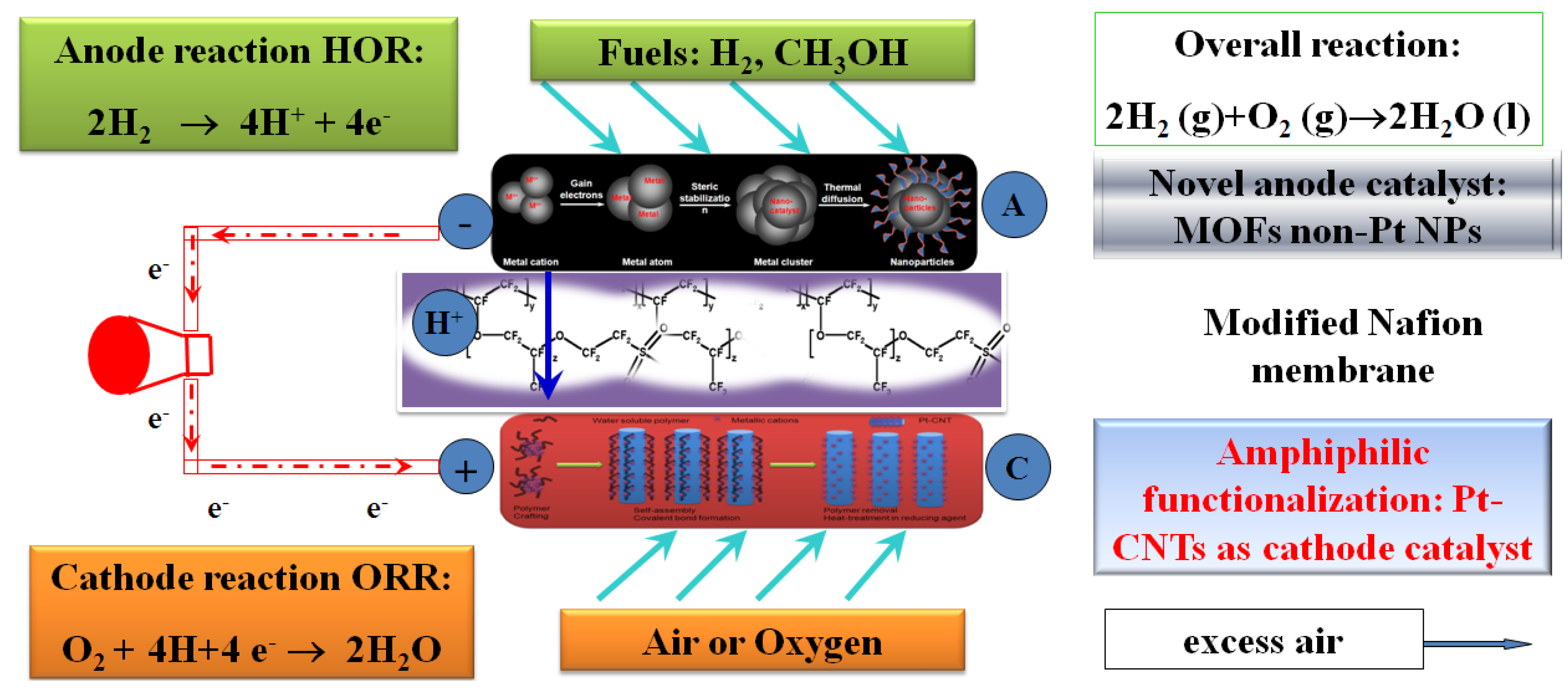
3]. One class called proton exchange membrane fuel cells (PEMFCs,
Figure 1) are devices drawing significant attention. PEMFCs consist of a solid Nafion polymer membrane as the electrolyte, utilizing H
2, bio-fuel, or fossil fuel as a fuel source, and noble metal as the catalyst [
4]. PEMFCs provide direct electricity for stationary and portable applications, such as lighting, laptops, or other electrical appliances, and automobiles [
5]. FCs provide high energy conversion efficiency, low pollutant emissions, simple operation, and flexible fuel supply [
6]. However, current PEMFC designs encounter problems, such as H
2 gas arrangement, materials compatibility, manufacturing cost, performance degradation, heat transfer, interaction between individual FCs, and stack transport [
7].
Figure 1.
The operation schematic of proton exchange membrane fuel cells (PEMFCs).
Figure 1.
The operation schematic of proton exchange membrane fuel cells (PEMFCs).
There have been many efforts to study the performance and durability of PEMFC devices [
8]. Air flow and heat transfer modeling, electrochemical modeling, and thermo-mechanical modeling of PEMFC devices are extensively studied [
9]. Each study shows a promising solution to improve the performance and durability of PEMFCs [
10]. The anode and cathode catalysts for the PEMFCs are critical for improving PEMFC kinetics and stabilities and lowering the manufacturing cost [
11]. Commonly used catalysts are composed of pure gold (Au) [
12,
13], platinum (Pt), carbon supported Pt, and its alloy, but are plagued by the high expense of Pt and low resistance to carbonaceous species resulting in catalyst poisoning [
14]. Other approaches to circumvent these design and operating drawbacks have focused on use of Pt alloy supported carbon nanotubes (CNTs) and nanofibers, which are also subject to performance degradation, low corrosion resistance, and limited cost-effectiveness [
15]. Thus, one possible avenue to minimize manufacturing cost and increase operating lifetime is the use of non-Pt metal catalysts; however, their heterogeneous catalysis, durability and carbonaceous species tolerance behavior require further development for robust, durable, and efficient PEMFC construction and operation [
16]. It is also important to solve the problematic electrode flooding which is caused by water condensation at the cathode [
17]. This liquid water trapped in the cathode layer can be further converted to H
2 and O
2 via electrolysis [
18]. This approach can reduce the electrode flood and generate fuel which consequently improves the fuel gas (H
2) arrangement [
19].
In our research, aligned carbon nanotubes (ACNTs) were fabricated and functionalized by Pt nanoparticles using a post-modification technique. The work described in this paper incorporates three novel strategies: (1) use of chemical vapor deposition (CVD) technique for the synthesis of the ACNTs with the controlled structure and pore size to advance PEMFC devices. The noble metal Pt loading was significantly lower than the traditional devices; however, the power density of the devices composed of Pt-functionalized ACNTs nanomaterials was well-maintained and even superior to current designs; (2) incorporation of nano-materials into macrodevices to convert chemical energy into electricity, which gives the advantages of increased specific surface area, high reaction rate, and improved performance of the devices, and the advantages of the macrodevice (ease of use, portability, device ruggedness, low manufacturing cost) were also incorporated. The integration of nanotechnology and macrotechnology in this regard is novel; (3) the selection of optimal fabrication variables for device construction was correlated with field emission scanning electron microscopy (FESEM) and Raman spectrometry to determine particle size, fine structure and molecular vibration mode.
2. Results and Discussion
This study indicates that highly ACNTs allow for a novel structure to be created, which channels gas diffusion through a Pt-functionalized ACNTs array. This enhances the chemisorption of the gas reactants and promotes properties of the PEMFC device. ACNTs hydrophobicity also provides a new tool to prevent cathode flooding, resulting in long-term stability of PEMFCs. The particle size and elasticity were used as a “thermometer” value to optimize the ACNTs fabrication incorporated into the nanoparticles, since a specific range of particle size gave rise to the most optimal electrochemical properties of the PEMFC devices.
2.1. Integration of Nano-Micro-Macro Structure to Construct PEMFC Units
The state-of-the-art in nanotech has been demonstrated in the exponential rise in publications [
20]. However, concerns remain due to the fact that nanomaterials show potential toxicity and carcinogenicity, or lack of mechanical strength [
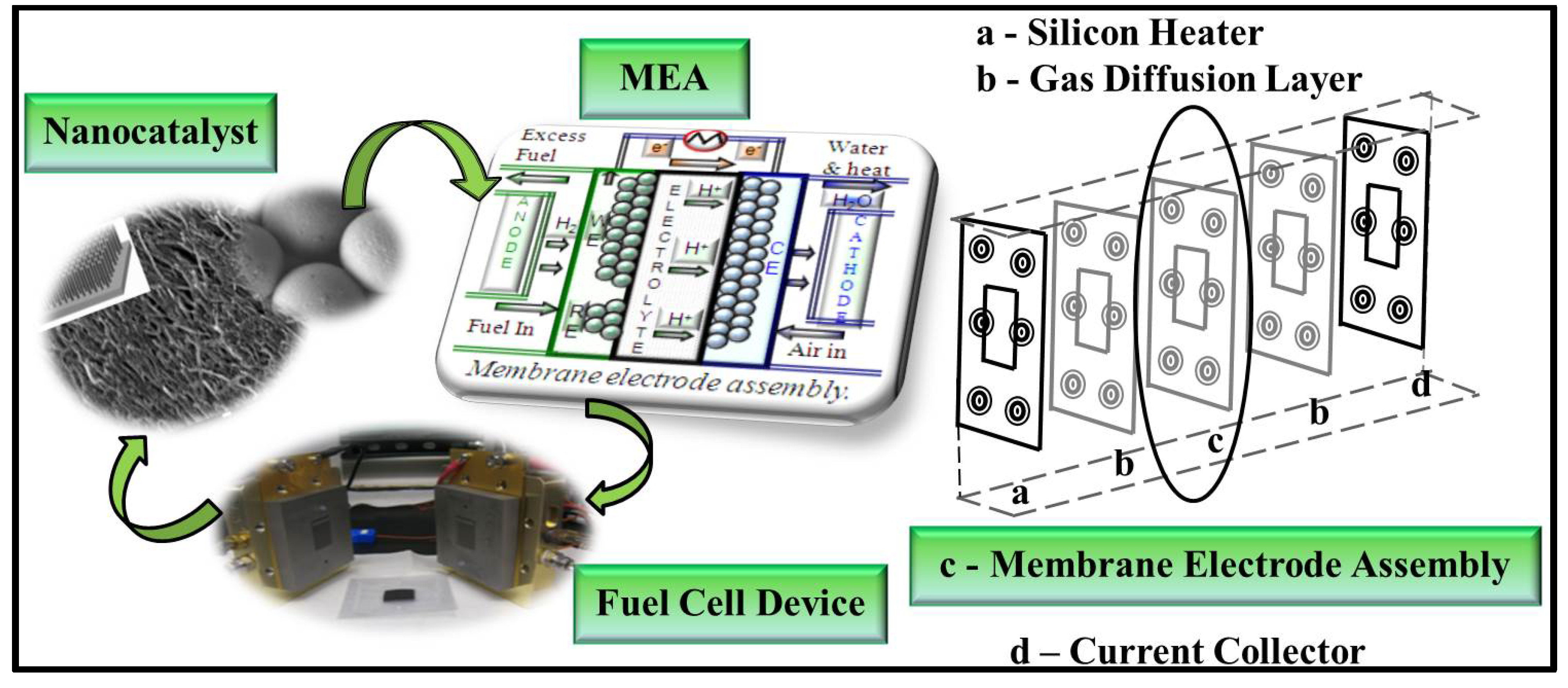
21]. Ideally nano-micro-macro integration (
Figure 2) is able to provide new direction for nanomaterials’ design and application, which has not been reported. In this activity, the nanocatalysts are redirected to form macro-level systems for exploration of novel nano-phenomena used for efficient energy conversion. The gas-diffusion layer is used as a macro-matrix to allow deposition of PEMFC catalyst. The anode, metal-organic frameworks (MOFs) embedded non-Pt catalyst and cathode materials (Pt-CNT) are placed on two sides of the Nafion membrane. Hot pressing is utilized to fabricate the membrane electrode assembly (MEA) under various temperatures and pressures. To construct the PEMFC devices, the MEA will be placed in the center of the gasket, containing three-polymer layers on each compartment to separate the H
2 and O
2.
Figure 2.
The hierarchy of the nano-micro-macro integration: platinum-carbon nanotube (Pt-CNT) arrays as cathode catalyst; metal-organic frameworks (MOFs)-Co/Ni as anode catalyst and gas storage. The membrane electrode assembly (MEA) was packaged between two graphite bipolars to evaluate the performance.
2.2. Microscopic Analysis of PEMFC Devices
Scanning and transmission electron microscopic (SEM/TEM) images (
Figure 3) indicate that the diameter of CNT arrays is approximately 4–15 nm and length varies from 8 µm to 20 µm according to its growth time period and flow rate of reactants [
22]. PEMFCs composed of the Pt-CNT arrays exhibit unique structures to channel the gas readily to the catalyst and CNT structure can be tuned into multi-walled nanotubes with 5–19 layers depending on the nature of the Pt-CNT. The post-functionalization of CNTs via van der Waals interactions provided the following advantages: (1) the geometry of alignment was maintained; and (2) hydroxyl (O–H) group was introduced into the curvature of nanotubes. The processing was completed through three steps. Firstly, water soluble Pt
4+ compounds were sprayed onto the surface through intermolecular forces (such as ion-dipole crosslinking). Secondly, step-wise deposition of metallic cations onto charged CNT surface assisted self-assembly of amphiphilic block copolymers followed by formation of covalent bond with the CNT “backbones”. Lastly, graft copolymerization onto reactive seeded particles allowed cations to link with the CNT backbones. Pt-ACNT was used as the cathodic catalyst to provide high electrochemical performance due to the orderly structure and high specific surface area, as well the large triple phase boundary.
In addition, the ACNT structural and surface area support allow for high dispersion of Pt with lower loading, with increased Pt utilization and consequently reduced manufacturing costs. The hydrophobicity of ACNT also prevents cathode flooding and favors water management. It is commonly agreed that CNT displays several structures and the sp2 hybridization of carbon atoms allows C–C double bond formation, which further advance the stability of the materials. Multi-walled nanotubes are our targeted materials due to their unique structure and high hydrophobicity.
Figure 3.
The microscopic characterization of functionalized CNTs: (a) the scanning electron microscopic (SEM) micrograph of aligned carbon nanotubes (ACNTs); (b) the van der Waal intermolecular forces is the major driving force for the CNT functionalization; (c) two lattice vectors of graphite to demonstrate the CNT circumference, which is equal to the length of the vector (n1a1 + n2a2), and the CNT chiral angle between vectors (n1a1 + n1a2) and a1; and (d) the transmission electron microscopic (TEM) micrograph to show the nanoscaled Pt, which was deposited on the surface of the nanotubes to increase the triple phase boundaries.
2.3. Spectroscopic Analysis of PEMFC Devices
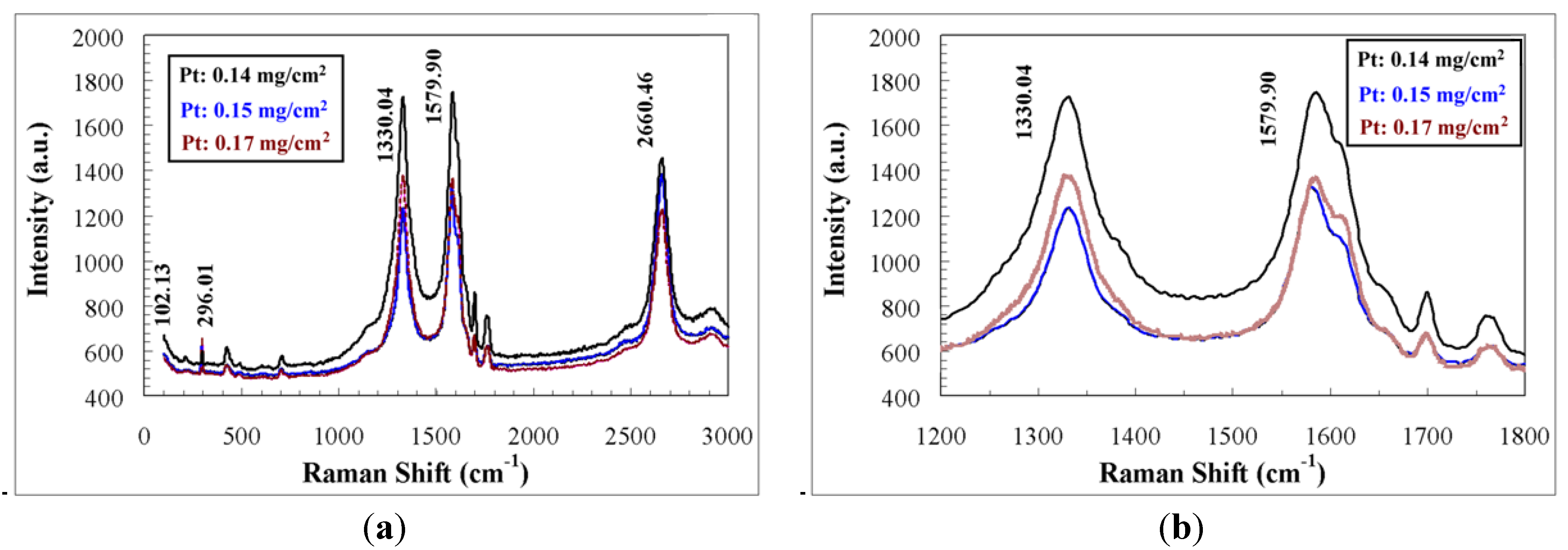
Raman spectroscopy provides powerful tool to characterize one-dimensional ACNTs with various Raman active modes. From the spectra of three selected ACNTs (
Figure 4a), it can be seen that the orderly arranged structure of the ACNT contributes significantly to its unique optical and spectroscopic properties, due to the one-dimensional confinement. Various features of the ACNT are highly corresponding to the vibration modes. The radial breathing mode (RBM) occurs at 212.15–225.56 cm
−1, resulting from the symmetric in-phase arrangement of carbon atoms sp
2 hybridization in the ACNT. At the frequency of 1330.00 cm
−1, the vibration is classified as the D mode, resulting from the defect induced second order feature. At 1584.17 cm
−1, a G-band occurs and 1759.28 cm
−1 mode occurs, respectively. At high frequency of 2662.59 cm
−1, G’ mode vibration is also detected. The zoomed-in spectra of D and G bands (
Figure 4b) indicated that there exist large amount of defect of the multi-walled nanotubes due to the equivalent intensity of both modes. Additionally the Breit-Wigner-Fano lineshape observed in G band suggested that the so-prepared ACNT displayed metallic behavior, favorable to the electron conductivity. The Pt metal displays two characteristic spectra at frequency of 483 cm
−1 and 2085 cm
−1, respectively. Some satellites spectra were also observed due to the complexity of the MEA elemental composition and structure. Most importantly, the mode frequency of ACNT and Pt depends on the laser excitation and the dimensional confinement. Previous studies reported a similar electrochemical energy storage enhancement indicated by Raman spectroscopy for the modified multi-walled CNTs using ether and carboxylic acid functional groups [
23,
24].
Figure 4.
The Raman spectroscopic analyses of Pt-functionalized ACNT (three selected samples were shown): (a) Raman spectra for MEA; and (b) zoomed-in Raman spectra of these three specimens.
Figure 4.
The Raman spectroscopic analyses of Pt-functionalized ACNT (three selected samples were shown): (a) Raman spectra for MEA; and (b) zoomed-in Raman spectra of these three specimens.
2.4. Electrochemcial Analysis of PEMFC Devices
The electrochemical performance of the single PEMFC under various cell operating conditions was systematically performed. The open circuit potential and current density were measured and used for the power density determination. In order to obtain stabilized electrochemical performance, the PEMFCs were conditioned for 10 h under flow rate of 100 mL/min for H2 and 300 mL/min for O2, respectively. Cell temperature was maintained at 80 °C. In this study, the cell potentials were varied at three constant values of 0.512, 0.597 and 0.699 V to ensure the polarization under low direct current (DC). It can be seen that the cell performance was enhanced upon the conditioning and reached constant current density after 8–10 h according to the various PEMFC specimens. The novelty of this approach is application of ACNTs, which allows for an improved performance due to rapid gas diffusion and chemisorption of the gas reactants. ACNT hydrophobicity also provides a new tool to prevent cathode flooding, resulting in long-term device stability.
After 10-h conditioning of the PEMFCs, the current density (
io), power density (
Po) and charge transfer resistance (
Rct) were then systematically measured using electrochemical spectra (
Figure 5a). A commercial FC test station and potentiostat/galvanostat (both available at the Argonne National Laboratory, Fuel Cell Technologies, Inc., Argonne, IL, USA) were used to test the PEMFC performance. The pressurized and humidified H
2 and O
2 (air) were fed into the anode and cathode chambers under various flow rates. The cell operating conditions were controlled at various temperatures (from 70 °C to 110 °C with increments of 5 °C). The data collection was manipulated by LabView 7, CorrView and ZView software
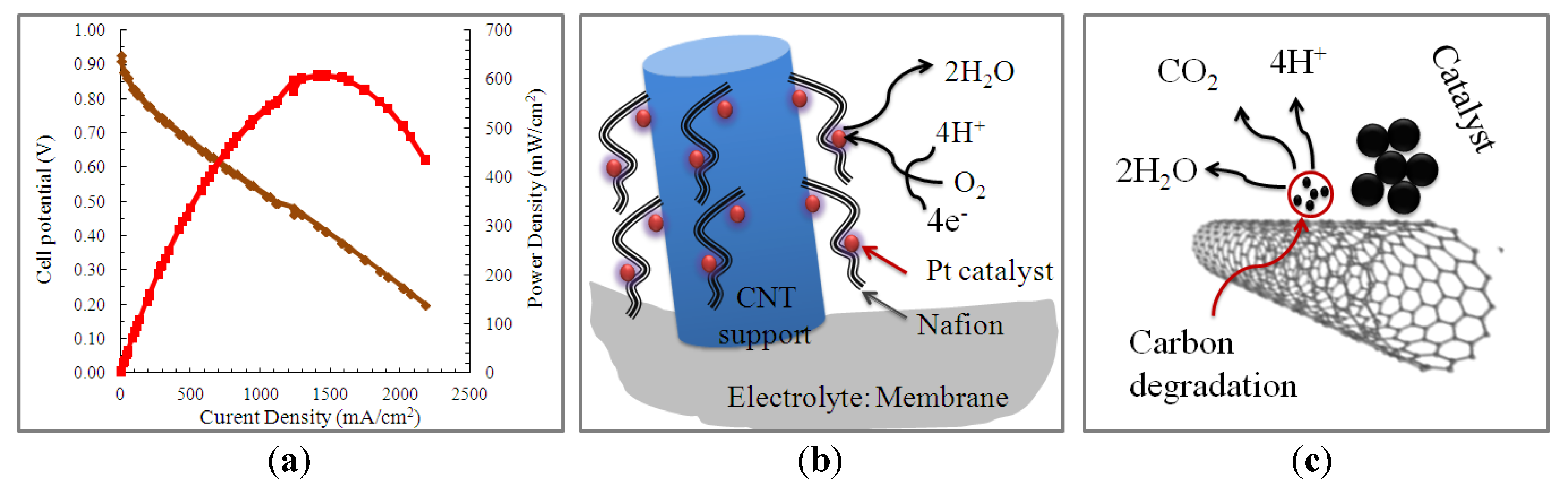
TM. Electrochemical data indicated that the maximum current and power density were ranging from 2250 mA/cm
2 to 3200 mA/cm
2 and from 600 mW/cm
2 to 900 mW/cm
2, respectively. The open circuit potential was determined to be varying from 0.945 V to 0.997 V at reduced Pt load of 0.2 mg/cm
2 at ambient pressure. Importantly, the functionalization of ACNT secured the Pt dispersion (
Figure 5b) and prevented the Pt from deterioration resulting from the Ostwald ripening (
Figure 5c) due to introducing the amphiphilic group. This activity enhanced the PEMFCs performance and simplified their design via applying our novel catalysts. The stability of the PEMFCs has been evaluated within 10-h operating time window. The data indicated that the current density changed by about 3% (±1.5%), suggesting high stability of the MEA performance.
Figure 5.
(a) Electrochemical performance of PEMFCs composed of Pt-functionalization ACNT as catalyst; (b) the post-functionalization allowed for Pt monodispersion and alignment of nanotubes; and (c) Pt and C degradation were prevented due to introducing the amphiphilic groups.
Figure 5.
(a) Electrochemical performance of PEMFCs composed of Pt-functionalization ACNT as catalyst; (b) the post-functionalization allowed for Pt monodispersion and alignment of nanotubes; and (c) Pt and C degradation were prevented due to introducing the amphiphilic groups.
Compared with the PEMFCs composed of the commercially-available ink-based catalyst, the Pt-ACNT PEMFCs displayed high current and power density (
Table 1). However, the reproducibility of commercial catalyst is significant.
Table 1.
The comparison of PEMFC performance between Pt-ACNT catalyst and commercially-available ink-based catalyst.
Table 1.
The comparison of PEMFC performance between Pt-ACNT catalyst and commercially-available ink-based catalyst.
| Pt-ACNT | Current density (A/cm2) | Power density (W/cm2) | Ink-based catalyst | Current density (A/cm2) | Power density (W/cm2) |
|---|
| Pt loading: about 0.2 mg/cm2 | 2.24 | 0.62 | Pt loading: about 0.7 mg/cm2 | 1.26 | 1.07 |
| 2.45 | 0.64 | 1.35 | 1.14 |
| 2.38 | 0.65 | 1.36 | 1.16 |
3. Experimental Section
In the experimental procedure, the fabrication method incorporated three steps: (1) synthesis of ACNTs; (2) nanostructural characterization of catalyst; and (3) electrochemical benchmark test of FC. To prepare the nanotubes and MEA, all chemicals unless specified were obtained from Sigma-Aldrich (St Louis, MO, USA). The solvents were obtained from VWR International (West Chester, PA, USA). The reagents were reagent grade and used without further purification. Doubly-distilled and 0.2 micron filtered (EMD Millipore Corporation, Billerica, MA, USA) water was used in the dissolution of the compounds. The CVD technique was used to control the diameter and length of nanotubes. In addition, the nanostructure of nanotubes was characterized by FESEM equipped with energy dispersive spectroscopy (EDS), and separately Raman spectroscopy was used to determine the morphology, elemental composition and molecular interactions between the nanotubes and Pt. To evaluate the elasticity and hardness of the Pt-decorated CNTs, nanoindentation tests were performed on the specimen surface using a table top Nanoindentation Tester. Furthermore, the electrochemical performance was conducted using an electrochemical incorporation test stand to determine the reduction and oxidation (Redox) reaction kinetics of the PEMFC devices.
The ACNTs were synthesized using CVD technique with a xylene-ferrocene solution as the precursor binary solvent. Xylene is the carbon source, while ferrocene provides the iron metal nanoparticles, which function as the seed catalysts for the nanotubes growth. Three 5 cm2 quartz substrates were placed inside quartz reaction tube. The tube was placed in a two stage furnace and tightly sealed from air. The first stage of the furnace was at a temperature of 225 °C, which sufficed to vaporize the solution. The second stage was held at 725 °C and used to carbonize the vaporized solution, depositing the iron nanoparticles on the quartz substrates, and allowing the CNTs to grow along the iron seeds. The solution with the chemicals was injected into the reaction tube, on the low temperature stage, using Ar and H2 as the carrier gases, at flow rates of 100 and 50 mL/min, respectively. The chemicals injection rate was selected to be maintained at 0.225 and 0.250 mL/min, respectively.
The surface morphology, cross-sectional images and the thickness of the ACNTs were determined using a FESEM (JSM6701F) equipped with X-ray EDS (JEOL USA, Inc., Peabody, MA, USA). An accelerating voltage of 20 kV and high vacuum of ca. 1.0 × 10⁻⁵ mbar were generally employed. The MEA was mechanically fractured using a razor, enabling an easier estimation of the PEMFC thickness. The Raman spectroscopic analysis was conducted to evaluate the vibration mode and electron structure of Pt and multi-walled nanotubes. Raman/Fourier transform infrared spectroscopy (FTIR, Horiba Jobin-Yvon LabRam IR system) confocal microscope (Horiba Scientific, Horiba Jobin Yvon, Edison, NJ, USA) was employed to obtain highly specific fingerprints to enable the precise chemical and molecular characterization and identification. The Raman module used was fiber optic coupler with the laser excitation lines at 632 nm with the scanning range of 100–3000 cm−1. The resolution was kept at 0.3 cm−1/pixel at various lines.
The ACNT-MEA has an active area of 5 cm2 and is mounted in a single cell for testing, with graphite bipolar plates and a single-serpentine flow field. Commercially available carbon cloth treated with Teflon is used as the gas diffusion layer (GDL) for anode and cathode, and inserted between the MEA and the bipolar plates. The single cell is attached to an Electrochem Inc. test stand (Woburn, MS, USA) to record the current-voltage (I-V) polarization curves, which gives a measurement of the MEA’s performance. The PEMFC devices are initially conditioned for about 10 h until it reaches the desired temperature and humidity conditions, using Ar gas in the anode and O2 gas in the cathode, at a constant voltage. After a constant current is reached, the polarization curves are measured by potentiostatically cycling the voltage between 0.2 V and 1.0 V. All tests are conducted at a cell temperature of 80 °C with H2 gas in the anode and air or O2 gas in the cathode, both gases at relative humidity of 100%. The gas flow rates are 100 mL/min at 1.2 bar and 300 mL/min at 1.5 bar for the anode and cathode, respectively.
4. Conclusions
The Pt-ACNT cathodic catalyst was obtained by the CVD, colloidal chemistry impregnation, and followed by heat-treatment at 300 °C. The catalyst was characterized through SEM and Raman spectroscopy to determine the unique structure and molecular interaction between C and Pt atoms. The results show that the dense ACNT layers have been directly grown on cathode materials with highly aligned structure, which favors the gas diffusion. The diameter of the ACNT is observed approximately 4–15 nm and its length varies from 8 µm to 20 µm according to the different growth time period. The Pt nanoparticles are uniformly distributed on the surface of ACNT, and the particle size ranges from 2 nm to 4 nm. The single PEMFC displayed the maximum power density 700–900 mW/cm2 under the O2 oxidant introduced into the cathode.


