Article

Radiation Protection at the Large Hadron Collider: Problematics, Challenges and Advanced Monte Carlo Simulation Techniques

CERN, European Organization for Nuclear Research, 1 Esplanade des Particules, Meyrin, 1217 Geneva, Switzerland
*
Author to whom correspondence should be addressed.
Submission received: 23 March 2022 / Revised: 18 April 2022 / Accepted: 20 April 2022 / Published: 25 April 2022

Abstract

:
This paper provides an overview of the problems, challenges, and the advanced simulation techniques used to study and plan complex interventions in radiation areas at CERNs Large Hadron Collider and its future upgrade to the High-Luminosity Large Hadron Collider. The operational radiation protection aspects are supported by state of the art simulations by means of the FLUKA Monte Carlo code and estimates conducted via other tools such as ActiWiz and SESAME, used within the HSE-RP group.

1. Introduction

In 2022 the Large Hadron Collider (LHC) will enter its third and final period of physics, called Run 3. In 2026–2028, during the Long Shutdown 3 or LS3, the LHC will be upgraded to the High-Luminosity Large Hadron Collider (HL-LHC) which will allow for a number of collisions 5 times larger than the nominal rate and to develop a plan of experimental physics until 2040 [1]. In this context, a number of Radiation Protection (RP) challenges will need to be addressed. The increase in luminosity will lead to a significant increase in radiation levels during the HL-LHC operation, as well as residual radiation during machine technical stops. In addition, the LHC upgrade requires for a number of activities to be carried out in highly radioactive environments. Among these, the decommissioning of nearly 800 m of accelerator elements such as magnets, collimators, passive absorbers, cables, vacuum and cryogenic components (LHC Point 1 and 5). In addition, both beam dumps (LHC Point 6) will be removed and replaced with new elements which can withstand the increased HL-LHC beam intensity. These two elements are among the most radioactive in the entire LHC ring, with dose rates in contact of a few mSv/h even after more than 3 years cool down. To ensure high radiation protection and safety standards, operational radiation protection [2] is supported by a series of tools, such as Monte Carlo codes, which allows to study and properly plan complex interventions. The CERN Radiation Protection Group (HSE-RP) makes extensive use of the FLUKA code [3,4,5], being an active member of the FLUKA CERN collaboration in the development, maintaining and benchmarking of the code. This work aims to provide an overview of the interventions related to the LHC upgrade during LS3 and the main radiation protection challenges in terms of optimization and reduction of dose to personnel (ALARA) [6,7] as well as the decommissioning of highly activated components (inner triplet, collimators, dumps). In addition, RP constraints and challenges for the HL-LHC operation will be discussed.

2. Materials and Methods

The characterization of the radiation field is essential to cope with the multiple effects of the interaction of regular and accidental beam losses on machine and detector components. In order to quantify these effects starting from the relevant loss term, multipurpose Monte Carlo codes represent a critical tool enabling the evaluation of macroscopic quantities through the microscopic description of particle transport and interaction in matter. At CERN, FLUKA [3,4,5] is the reference tool to assess the machine and radiation protection aspects. It is regularly and extensively used for the whole accelerator chain, from the low energy injectors up to the High Luminosity upgrade of the LHC: such a demanding task calls for a continuous improvement of the different interaction models as deeply described in [4]. This means that FLUKA can simulate with high accuracy the interaction and propagation in matter of about 60 different particles, including photons and electrons from 100 eV–1 keV to thousands of TeV, neutrinos, muons of any energy, hadrons of energies up to 20 TeV (up to 10 PeV by linking FLUKA with the DPMJET code) and all the corresponding antiparticles, neutrons down to thermal energies and heavy ions [3,8,9].
In addition to FLUKA, two other codes are widely used in CERN RP studies: SESAME and ActiWiz.
SESAME is a complementary tool to FLUKA which allows to perform, among others, residual dose rate calculations in complex geometry. The FLUKA-SESAME simulation chain consists in two steps. The first step is a prompt simulation with FLUKA to score the radionuclide inventory, including the decay coordinates, via a set of dedicated routines provided with the SESAME distribution. Those radionuclide information are then used as source term by FLUKA at second step after being manipulated by SESAME: the radionuclide decay coordinates and the geometry are modified, accordingly to user-defined roto-translations, to produce a more complex decay scenario as it will be shown in the following.
ActiWiz (AW) [10] is developed and maintained by the CERN RP group. The code is used for estimating the radionuclide inventory in a given material, providing the irradiation profile, the material composition and the particle environment at the equipment location. The subsequent convolution of the radionuclide inventory with legal limits and activity-to-dose conversion factors allow to assess and quantify different radiological hazards. In the present work ActiWiz has been mainly used for estimating the induced activity in different components for clearance purposes by calculating the multiple of the Swiss exemption limits (LL) [11].
In the following, examples of different Radiation Protection studies conducted at CERN in the context of the LHC upgrade and the HL-LHC operation will be presented and the details of the FLUKA models (geometry, beam losses, irradiation profiles, etc.) will be provided contextually.

3. Results and Discussion

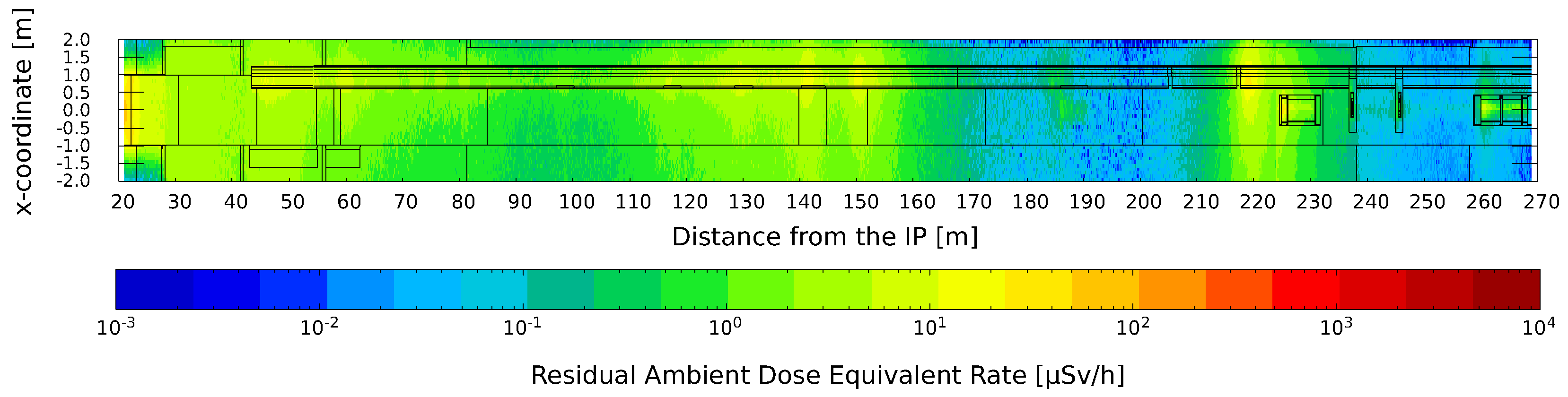
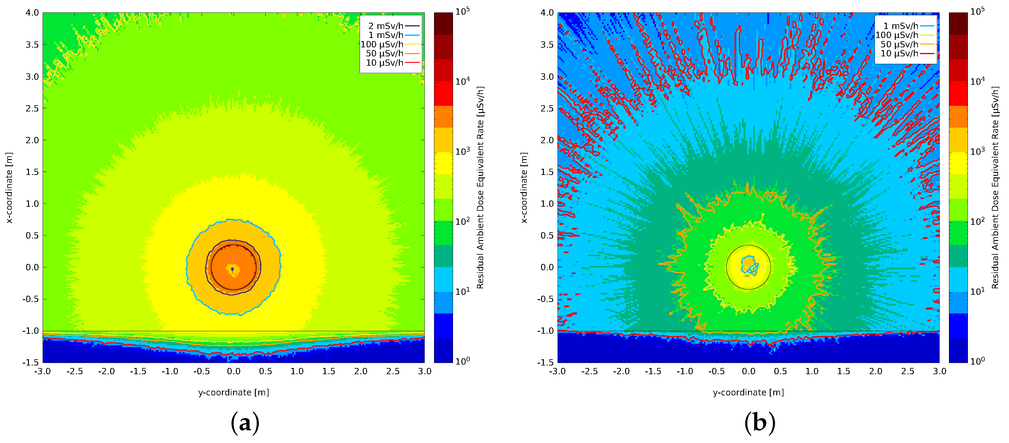
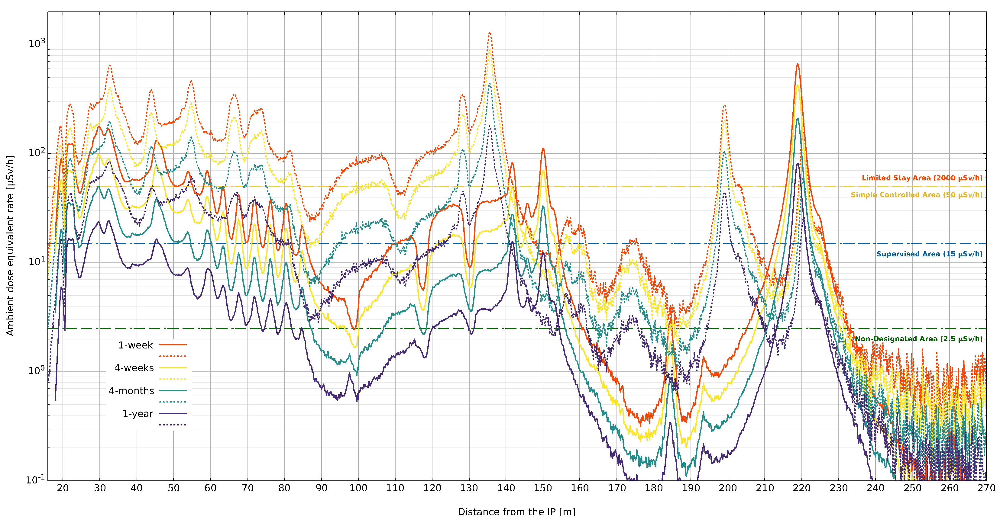
3.1. Radiation Levels in LHC after Run 3 Proton-Proton Operation

The radiation levels during LS3, in the so-called LHC Long Straight Section (LSS) of Point 1 and Point 5, have been estimated by FLUKA simulations [12]. The LHC has 8 straight sections (in opposition to the bended part of the tunnel infrastructure, the so-called “arc”) which serve as experimental or utility insertions. There are two high-luminosity experimental insertions located at Point 1 (ATLAS) and 5 (CMS) and two more experimental insertions at Point 2 (ALICE) and 8 (LHCb), which also contain the injection systems. The beams only cross at these four locations, being the experiment insertions, and are focused onto the interaction point by superconducting low-beta triplets (quadrupoles). Insertions 3 and 7 each contain the collimation systems, momentum and beta-cleaning, respectively. Insertion 4 hosts the RF system while insertion 6 contains the beam dumping system [13]. In the following, LSS1 and LSS5 will be described more in details being the main topic of this section. The simulations considered the combined operation of the LHC from the beginning of Run 1 (2010) to the end of Run 3 (2025). The irradiation profile used in the computation was produced from the luminosity data as recorded by the ATLAS and CMS experiment in Run 1 and Run 2. In addition, assumptions on Run 3 operation have been made based on data provided by the LHC operation team. Figure 1 shows a typical 2D map of the radiation levels in LSS1. These maps are produced for different cooling times ranging from a few hours to a few years after beam stop: these key cooling times provide the radiological environment relevant for different steps of the LS3 upgrade works. The map shows only half of the LSS (∼270 m, right side Point 1) since the radiation levels are approximately symmetric with respect to the Interaction Point (IP). The main hot spots are visible at the main beam line elements such as (from left to right of Figure 1) the Inner Triplet quadrupoles (IT, 20–50 m from IP), the separation dipole D1 (six modules, 60–85 m), the neutral absorber TAN (140 m), the beam 2 tertiary collimators (TCT, 145 m) and the beam 1 luminosity debris collimator (TCL4 150 m, TCL5 185 m, TCL6 220 m). Figure 2 shows the residual ambient dose equivalent rate profiles in LSS1 and LSS5: while for the large fraction of the LSS the profiles show similar results, differences are observable at the level of the TCL4 mainly due to the different crossing scheme at the IP (IP1 vertical crossing, IP5 horizontal crossing).
During LS3 the majority of the elements present in the LSS will be removed to allow for the installation of new elements which withstand with the HL-LHC operation. The dismantle of the beam line will be particularly challenging from the RP point of view due to the high activation level of some of the magnets/absorbers (up to a few mSv/h in contact, Figure 1) and the fact that this activity must be completed soon after the beam stop, ideally within 6 months. This constraint comes from the general LS3 planning and the need to remove the hot spots in the tunnel to proceed on with other activities such as the complete de-cabling of the LSS, civil engineering works and, finally, the installation of the new HL-LHC components.

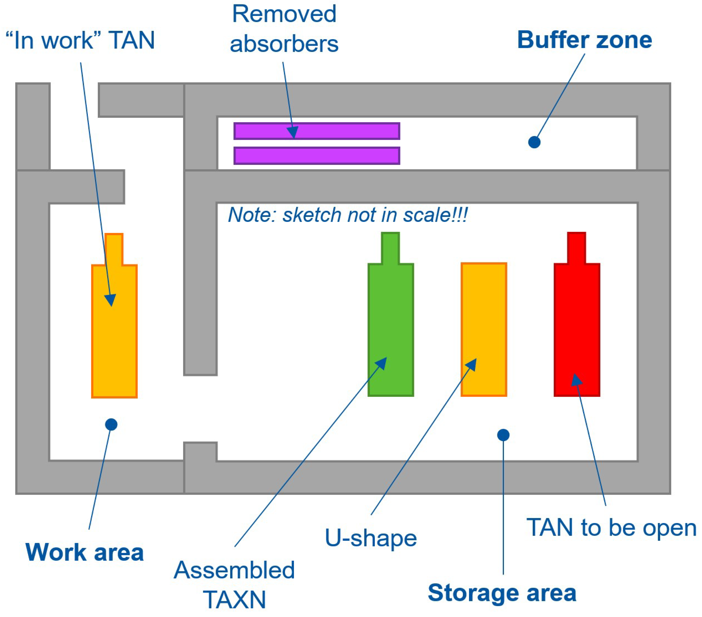
3.2. LHC QRL Dismantle

The cryogenic distribution line (QRL) provides liquid helium (1.9 K) to the cooling loops of the magnet cryostats and other cryogenic elements in the LHC [14]. During LS3 more than 800 m of QRL will be removed in LSS1 and LSS5 to be upgraded to new HL-LHC QXL. The upgrade will begin only after the dismantle and extraction of the main beamline elements (magnets, collimators, absorbers). FLUKA simulations allowed determining the radiation environment in the LSS when the beamline elements are completely removed (Figure 3). Compared to Figure 1 the radiation levels in the tunnel are significantly lower, showing a peak residual dose rate of 40–50 μSv/h (∼220 m from IP) and an average <10 μSv/h in contact with the QRL. It is important to underline that despite the absolute average dose rate is relatively low, the intervention will last several weeks with several workers/teams involved potentially leading to significant integrated individual/collective dose that must be accurately evaluated based in the detailed intervention procedure (called “Work Dose Planning”, WDP, in CERN jargon). In addition to the external exposure, the risk of possible internal contamination shall be considered by taking into account the cutting technique (different options currently under discussion). Further studies need to be performed to evaluate other constrains allowing to reduce the exposure/contamination risk when the details of the intervention will be finalized.
The characterization of the radioactive waste is conducted by using ActiWiz. FLUKA particle fluence (neutrons, protons, charged pions, photons) scored at the level of the QRL were coupled with nuclide production cross sections and the LHC irradiation profile to compute the radionuclide inventory and to compare with the Swiss exemption limits (LL) [11] adopted at CERN. The QRL will be considered radioactive for several years (>20) after the end of the LHC physics program: therefore, it will be disposed of as radioactive waste accordingly to the different elimination paths in place at CERN.

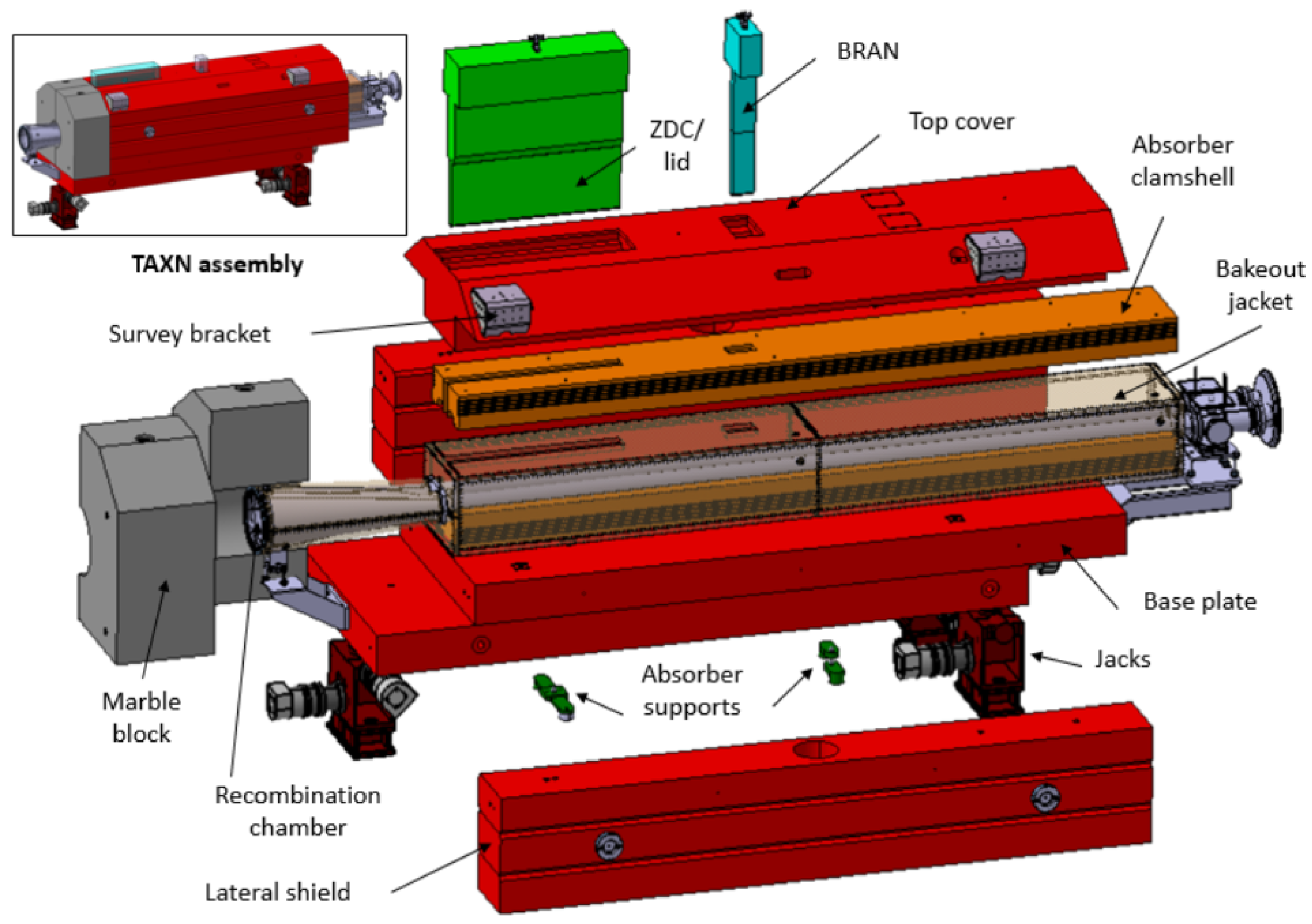
3.3. TAN to TAXN Upgrade
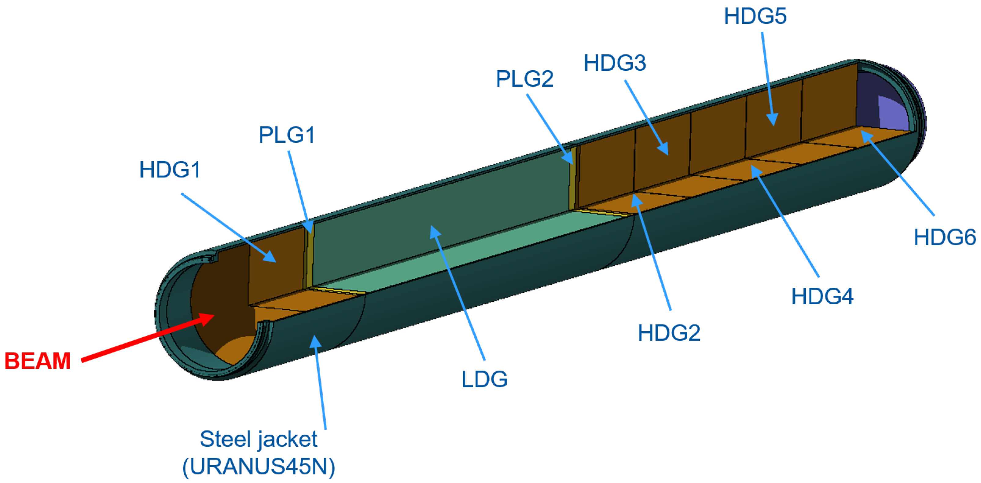
The Target Absorber Neutrals (TAN) is the component in the LHC LSS where the two proton/ion beams are recombined in a common vacuum chamber and it provides the necessary protection to the downstream superconducting magnets of the Matching Section (Q4 to Q7) in order to avoid quenching. Indeed, the TAN is designed to absorb the flux of forward high-energy neutral particles produced at the interaction point while allowing for enough aperture to reach the optic goals (larger crossing angle and beam size) [13]. The increasing particle debris from LHC to HL-LHC will require a new design of the TAN, called TAXN (HL-LHC Target Absorber Neutrals), capable to withstand with the higher beam conditions. The TAN/TAXN (Figure 4) share a very similar mechanical layout and are mainly composed by a copper absorber, a steel (ASTM A36) and a marble shielding and a recombination chamber (“Y-chamber”). In total, four TAN (2× LSS1 and 2× LSS5) will be dismantled from the LHC and replaced/upgraded during LS3.
Some of the TAN components will be reused in the new TAXN, namely the low carbon steel and the marble shielding while the top cover, the Y-chamber and the copper absorber will be replaced with new ones. In order to reuse these parts it will be necessary to open the TAN after its extraction from the LHC tunnel. The main steps for this upgrade [15] can be summarized as the following: (1) evacuation of the TAN from the LHC tunnel; (2) storage of all four TAN in a surface building; (3) dismantling of the copper absorber and Y-chamber to leave only the lateral/bottom shielding to reuse; (4) modification/machining the existing shielding; (5) installation of the new absorber and Y-chamber into the existing shielding and the installation of the new top shielding; (6) storage of all the upgraded TAXN (7) installation of the TAXN in the HL-LHC tunnel. Firstly, the radiation levels at the TAN area after the end of Run 3 proton-proton operation were estimated to plan the extraction of the TAN from the LHC tunnel and the following transport in surface. To integrate the upgrade of the TAN into the global LS3 master schedule, the extraction of the TAN is currently foreseen after four months cool down from the end of proton-proton physics. This step was conducted using the FLUKA model showed in Figure 1. Radiation levels after the end of LHC Run 2 operation have been measured as part of the routine RP controls/surveys. The residual dose rate measured at the level of the TAN was compared with FLUKA simulations showing an excellent agreement: <20% difference was observed.
Secondly, FLUKA was coupled with SESAME to simulate the storage, dismantling and upgrade of the TANs. The global dose field due to the presence of all four TAN in the same environment is shown in Figure 5. Isodose lines at 2.5, 15, 100 and 1000 μ Sv/h are highlighted in Figure 5: it is possible to observe that the iso-dose line at 100 μ Sv/h is fully included within the TAN shielding, i.e., <100 μ Sv/h are expected in contact with the TAN fully assembled.
The dismantling and upgrading of the TAN was divided in two major steps, studied via SESAME-FLUKA simulations. The first configuration considered the TAN without the top shielding and the forward physics detector (ZDC/BRAN). The second configuration refers to the machining of the remaining lateral/bottom TAN shielding (so-called “U-shape”). All the above estimates allow for an optimized (ALARA) planning of the upgrade activities. In addition, some preliminary considerations on the worksite layout can be made by planning for a dedicated area for the storage of the TANs, a workspace for machining/upgrading the TAN and a buffer zone for radioactive waste (accessible via a crane) Figure 6. The worksite layout shall account for a dedicated shielding which will be designed based to cope with the radiological classification of the surrounding area/building.

3.4. LHC Beam Dump

The LHC beam dump (TDE) allows for absorbing the 7 TeV proton beam in a controlled manner. Two TDE are present in the LHC machine layout, one for each beam. The TDE are installed in two dedicated galleries (called UD62/UD86), ∼750 m downstream the IP6. The TDE is made of different blocks of graphite (Figure 7) with different densities: 1710 × 2 mm thickness sheets of low-density graphite (Sigraflex, LDG = 1.1–1.2 g/cm 3 ) and 5 × 700 mm in diameter blocks of High-density graphite (Sigrafine, HDG = ∼1.77 g/cm 3 ). The graphite is contained in a 318LN (URANUS 45N) steel vessel and the full assembly is surrounded by a shielding made of iron and concrete to reduce the residual radiation levels during interventions in the UD galleries [13].
The two operational TDE used in Run 1 and Run 2 were extracted during LS2 (2019–2021) and the two available spare dumps where upgraded to be used during Run 3 operation. The removal of the old operational dumps posed significant RP challenges due to the high residual dose rates up to almost 10 mSv/h in contact even after 1 year of cool down. In addition, it was decided to conduct a “post-mortem” analysis (Post Irradiation Examination, PIE) to examine the status of the LDG after two operational runs: this information is crucial for the design of the HL-LHC TDE which will need to withstand with higher beam intensity.
The PIE requires to open (autopsy) the highly activated TDE in order to access and inspect the LDG sheets. For this reason, a dedicated working area has been created in one of the surface buildings at LHC Point 6 (Versonnex, France). The work area is delimited by 80 cm concrete blocks to cope with the area classification of the building and to protect workers outside the worksite. The TDE autopsy has been realized in February 2022. The TDE has been cut in different pieces: while the LDG block will undergo a PIE, the other sections containing the HDG will be disposed of as radioactive waste. FLUKA-SESAME simulation have been carried out to study and optimize (ALARA) the autopsy sequence. Figure 8 shows the ambient dose rate H ˙ ( 10 ) 2D maps of two different steps of the TDE autopsy, after 3 years cool down from the end of Run 2 proton-proton operation.
Figure 8a shows the residual H ˙ ( 10 ) , in the transverse plane, when the TDE is fully assembled (i.e., configuration pre-autopsy): ∼2 mSv/h have been estimated in contact with the TDE. A RP survey has been conducted prior the TDE autopsy by using a dedicated robot remotely controlled to reduce dose to personnel: the residual dose rate profile along the two sides of the dump was measured and compared with FLUKA-SESAME simulations showing an agreement better than 20% (maximum deviation observed). It is important to note the uncertainty in the Co-content in the 318LN steel which has a direct impact on the production of Co-60 via neutron capture and therefore on the residual dose rate. The simulations considered a Co-content of 0.07 wt% (percentage weight fraction) in the 318LN steel: this value has been used based on a measurement conducted on a non-activated piece of the same type of steel. However, based on the feedback received from our material experts at CERN, the variability of the Co-content batch-to-batch at this very low-level could be within a factor 2.
Figure 8b shows the residual H ˙ ( 10 ) when the 318LN steel vessel is completely dismantled and removed from the work area, leaving the LDG exposed for the PIE: a significant reduction of the radiation background in the area can be observed. The optimization of the autopsy sequence by using FLUKA-SESAME simulations allowed for reducing the individual/collective dose to personnel involved in the intervention and in the following inspection/PIE of the LDG. In particular, the cut/removal of the steel vessel was a crucial step in the optimization of the work procedure. Indeed the activation of the vessel is dominated by Co-60 and Mn-54, which contribute for the ∼83% and ∼15% to the residual dose rate (estimated from ActiWiz).
Finally, the disposal of the two TDE was studied combining FLUKA particle spectra and ActiWiz to compute the radionuclide inventory after 3 years cool down and to compare with the declaration limit for the disposal in France: the dumps will be finally disposed of at the “Centre de Stockage de l’Aube (CSA)” of ANDRA.

3.5. Radiation Levels during HL-LHC Operation and Beam Stops

The increasing luminosity in HL-LHC will lead to an increase in the prompt and residual ambient dose equivalent rate [1]. Figure 9 shows the comparison between the expected radiation levels after Run 3 (LHC) and Run 4 (HL-LHC) operation.
The plot compares LSS1 in the LHC and HL-LHC (optics 1.5) configurations. To allows for more collision at the IP, HL-LHC will use a different optics/machine layout with respect to LHC: the crossing scheme at IP1/5 in HL-LHC will be swapped (i.e., IP1 horizontal crossing, IP5 vertical crossing) and some elements in the LSS will be moved/replaced. For example, the TAXN and the TCL/TCT collimators are moved toward the IP, from ∼140 m in LHC to ∼130 m in HL-LHC. These changes are visible in the plot, causing the horizontal shift of some peaks. A slight different pattern is observable also at the level of the Inner Triplet-D1 area (20–80 m) due to the different mechanical layout (e.g., larger aperture IT; one superconducting separation dipole instead of six normal conducting magnets) and/or position of those elements. The swapping of the crossing angle (vertical to horizontal at Point 1) is mainly visible at the level of the TCL4 collimator (∼135/150 m from IP1), where higher radiation levels are expected in the HL-LHC era.
In general, residual radiation levels are expected to increase with instantaneous luminosity for short cooling times (residual dose mainly driven by the last hours of operation) while a scaling with integrated luminosity is expected for long cooling times (from a few months to several years). All routine interventions performed in the LHC will face a potential significant increase of the external exposure in the HL-LHC era. To minimize the individual and collective dose, remote handling and alignment systems are being developed. Finally, with regard to new components, the need of intervention/maintenance is optimized at the design phase by choosing appropriate materials that minimize activation (e.g., low Co- content steels) and /or radiation-hard components (e.g., insulators, cables, etc.).

3.6. Cobalt Content in Steels

Construction materials used in the accelerator field, such as stainless steels, may contain cobalt as trace element. Despite its low mass content, cobalt traces may cause radiological risks through the production of the radionuclide Co-60 which has a half-life of 5.72 years. Naturally occurring cobalt is composed by one stable isotope, Co-59, which converts into Co-60 by low-energy neutron capture. At long decay times (e.g., >1 year), Co-60 may even dominate the radiological environment: indeed, Co-60 β decays to the stable isotope Ni-60 by emitting two high-energy gamma rays of 1.17 and 1.33 MeV, respectively. In planning new accelerator facilities or beam line elements, the induced radioactivity and the radiological hazard related to interventions (exposure of personnel) and decommissioning (radioactive wastes) must be taken into account from the early design phase for optimization purposes in respect of the ALARA principle [7]. Based on an internal study conducted by analysing the steel market and the radiological risk CERN has started to adopt a guideline value of maximum 0.1 wt% Co-content in steels [12]. However, this value is not always achievable depending on several factors such as the quantity of steel to be purchased, origin country of the supplier (due to possibly different technical standards and or regulations adopted), the type of steel (e.g., non-nuclear grade steel) and more. Therefore, HSE-RP conducts dedicated radiological risk assessments when the guideline value cannot be achieved or it is not known precisely. To determine the stainless steel activation a database has been created: the database is composed of lookup tables that provide, for each element in the LHC LSS and for different cooling times, the ambient dose equivalent rate at 1 m per unit volume ( μ Sv h 1 cm 3 ), the Co-60 contribution to the H ˙ ( 10 ) , the multiple of the Swiss clearance limits (LL). These tables have been produced by FLUKA-ActiWiz simulations by considering 304L steel as baseline material and a variable Co-content (C 0.03, Cr 18.50, Co 0.10/0.15/0.20/0.30, Fe 67.0825, Mn 2.00, Ni 11.25/11.20/11.15/11.05, P 0.0225, Si 1.00, S 0.05 wt%). Despite the database is a valuable tool for a preliminary evaluation of the radiological risk, there might be situations in which a full FLUKA simulation is necessary such as for new elements or bulky components with a complex geometry and/or far away from the beam line. These studies consider the radiological risk for intervention (external exposure) as well as the impact on future radiation wastes by computing the contribution of Co-60 to the multiple of the Swiss clearance limits (LL).

4. Conclusions

The LHC high-energy primary beam and the secondary particle shower produce a prompt and a residual radiation field that pose unique Radiation Protection challenges. In addition, in the design of new high-energy accelerators such as the HL-LHC, RP studies have to anticipate changes in legislation and in operational performance to avoid later expensive retrofitting. This requires expertise and knowledge across different fields and the use of the state-of-the-art simulation techniques and tools. In the context of the LHC upgrade toward the HL-LHC, the CERN RP group is called to provide support to a series of activities such as the dismantling/decommissioning of more than 800 m of beam line elements, highly activated beam dumps and collimators/absorbers, etc. These activities must cope with a tight schedule for completing the full upgrade within maximum 3 years. As shown in above examples, Modern Monte Carlo techniques are employed to produce detailed 3D maps of the residual dose rate field and the radionuclide inventory of activated equipment. These studies allow to plan and optimize (ALARA) each intervention in terms of individual/collective dose, dose rate and contamination risk. The induced activation is compared with clearance (LL) and disposal limits to determine the most suitable elimination path for radioactive waste in accordance with agreements made with CERN host states France and Switzerland. The same simulation techniques are used to produce predictive studies of the HL-LHC operation, supporting the design of infrastructure and components.

Author Contributions

Conceptualization and supervision, A.I. and H.V.; simulations and data analysis D.B., L.E., A.I. and M.M.; operational radiation protections aspects C.T.; writing and editing L.E. and A.I.; review A.I. and H.V. All authors have read and agreed to the published version of the manuscript.

Funding

This research received no external funding.

Institutional Review Board Statement

Not applicable.

Informed Consent Statement

Not applicable.

Data Availability Statement

Not applicable.

Acknowledgments

The Authors would like to acknowledge the colleagues from CERN BE-EA and SY-STI groups as well as the HL-LHC project management for the support and very useful technical discussions.

Conflicts of Interest

The authors declare no conflict of interest nor personal circumstances or interest that may be perceived as inappropriately influencing the representation or interpretation of reported research results.

Abbreviations

The following abbreviations are used in this manuscript:
LHCLarge Hadron Collider
HL-LHCHigh-Luminosity Large Hadron Collider
RPRadiation Protection
TANTarget Absorber Neutrals, i.e., LHC Neutral Beam Absorber
TAXNHL-LHC Target Absorber Neutrals
TDETarget Dump External, i.e., LHC external beam dump
ITInner-triplet
AWActiWiz
FLUKAFLUktuierende KAskade (Fluctuating Cascade)
LSSLHC Long Straight Section
LLLimite de Libération (exemption/clearance limit)
TCLLHC physics debris collimator
TCTLHC tertiary collimator
LSLong Shutdown
LDGLow-density graphite
HDGHigh-density graphite
QRLLHC cryogenic distribution line
QXLHL-LHC cryogenic distribution line
PIEPost-irradiation examination

References

  1. Béjar Alonso, I.; Brüning, O.; Fessia, P.; Rossi, L.; Tavian, L.; Zerlauth, M. High-Luminosity Large Hadron Collider (HL-LHC): Technical Design Report V. 1.0; Number CERN-2020-010, in CERN Yellow Reports: Monographs; CERN: Geneva, Switzerland, 2020. [Google Scholar] [CrossRef]
  2. Widorski, M.; Aberle, F.; Adorisio, C.; Perrin, D. Evaluation of radiation detectors for a possible integration into the automated survey system TIM in the Large Hadron Collider (LHC). In Proceedings of the IRPA14 conference, Cape Town, South Africa, 9–13 May 2016; p. 1239. [Google Scholar]
  3. CERN. FLUKA CERN Website. 2020. Available online: https://fluka.cern (accessed on 6 April 2021).
  4. Ahdida, C.; Bozzato, D.; Calzolari, D.; Cerutti, F.; Charitonidis, N.; Cimmino, A.; Coronetti, A.; D’Alessandro, G.L.; Donadon Servelle, A.; Esposito, L.S.; et al. New Capabilities of the FLUKA Multi-Purpose Code. Front. Phys. 2022, 9, 788253. [Google Scholar] [CrossRef]
  5. Battistoni, G.; Boehlen, T.; Cerutti, F.; Chin, P.W.; Esposito, L.S.; Fassò, A.; Ferrari, A.; Lechner, A.; Empl, A.; Mairani, A.; et al. Overview of the FLUKA code. Ann. Nucl. Energy 2015, 82, 10–18. [Google Scholar] [CrossRef] [Green Version]
  6. Vincke, H. ALARA Rule Applied to Interventions at CERN; Rev. 1.2; Technical Report; CERN: Geneva, Switzerland, 2017; Available online: https://edms.cern.ch/document/1751123 (accessed on 22 March 2022).
  7. Forkel-Wirth, D.; Roesler, S.; Silari, M.; Streit-Bianchi, M.; Theis, C.; Vincke, H.; Vincke, H. Radiation protection at CERN. In Proceedings of the CAS-CERN Accelerator School: Course on High Power Hadron Machines, Bilbao, Spain, 24 May–2 June 2011. [Google Scholar] [CrossRef]
  8. Mereghetti, A.; Boccone, V.; Cerutti, F.; Versaci, R.; Vlachoudis, V. The FLUKA Linebuilder and Element Database: Tools for Building Complex Models of Accelerators Beam Lines. In Proceedings of the IPAC2012, New Orleans, LA, USA, 2–25 May 2012; pp. 2687–2689. [Google Scholar]
  9. Vlachoudis, V. FLAIR: A Powerful But User Friendly Graphical Interface For FLUKA. In Proceedings of the International Conference on Mathematics, Computational Methods & Reactor Physics (M&C 2009), Saratoga Springs, NY, USA, 3–7 May 2009. [Google Scholar]
  10. Vincke, H.; Theis, C. ActiWiz–optimizing your nuclide inventory at proton accelerators with a computer code. Part of Proceedings, 12th International Conference on Radiation Shielding (ICRS-12) and 17th Topical Meeting of the Radiation Protection and Shielding Division of ANS (RPSD-2012). Prog. Nucl. Sci. Technol. 2014, 4, 228–232. [Google Scholar] [CrossRef]
  11. Swiss Federal Council. Ordonnance sur la Radioprotection (ORaP) du 26 Avril 2017; Recueil Officiel des Lois Fédérales, Ordonnance n; Swiss Federal Council: Geneva, Switzerland, 2018. Available online: https://www.admin.ch/opc/fr/official-compilation/2017/4261.pdf (accessed on 22 March 2022).
  12. Infantino, A.; Bjorkman, D. Radiation Protection Estimates for LS3 Activities in LHC LSS1 and LSS5. 2021. Available online: https://edms.cern.ch/ui/#!master/navigator/document?D:100712990:100712990:subDocs (accessed on 22 March 2022).
  13. Brüning, O.S.; Collier, P.; Lebrun, P.; Myers, S.; Ostojic, R.; Poole, J.; Proudlock, P. LHC Design Report; CERN Yellow Reports: Monographs; CERN: Geneva, Switzerland, 2004. [Google Scholar]
  14. Riddone, G.; Trant, R. The Compound Cryogenic Distribution Line for the LHC: Status and Prospects; LHC Project Report 612; CERN: Geneva, Switzerland, 2002. [Google Scholar]
  15. Infantino, A.; Elie, L.; Tromel, C.; Vincke, H. Preliminary RP Considerations on the TAN Dismantle, Storing and Upgrade during LS3. 2021. Available online: https://edms.cern.ch/ui/#!master/navigator/document?D:100901438:100901438:subDocs (accessed on 22 March 2022).
Figure 1. Projected radiation levels expected at LHC LSS1 at the end of Run 3 proton-proton physics: 4 months cool down.
Environments 09 00054 g001
Figure 2. Ambient dose equivalent rate comparison between LHC LSS1 and LSS5.
Environments 09 00054 g002
Figure 3. Projected radiation levels expected at LHC LSS1 at the end of the physics Run 3: 6 months cool down, LHC beam line elements removed.
Environments 09 00054 g003
Figure 4. Exploded TAXN assembly. The TAN shares a very similar mechanical layout (longer copper absorber).
Environments 09 00054 g004
Figure 5. Storing of all LHC TAN in surface. LS3, 4 months cool down after end of p-p operation.
Environments 09 00054 g005
Figure 6. Possible worksite layout, based on the preliminary estimates from FLUKA-SESAME simulations (for illustration purposes only, sketch not in scale).
Environments 09 00054 g006
Figure 7. Overview of the LHC TDE core, particular of the High- (HDG) and Low-Density Graphite (LGD).
Environments 09 00054 g007
Figure 8. 2D maps of the ambient dose equivalent rate during different steps of the LHC TDE post-irradiation examination (∼3 years cool down after end of Run 2 proton-proton operation). (a) pre-autopsy configuration (full TDE assembly); (b) final configuration (LDG fully exposed).
Environments 09 00054 g008
Figure 9. LHC LSS1 Vs HL-LHC LSS5 v1.5 (vertical crossing). Residual dose rate at different cooling times after Run 3 (LHC, solid line) and Run 4 (HL-LHC, dash line) at 100 cm distance from machine axis. CERN limits for radiation area classification (temporary-stay, i.e., <20% working time) are superimposed.
Environments 09 00054 g009
Publisher’s Note: MDPI stays neutral with regard to jurisdictional claims in published maps and institutional affiliations.

