
An SDR-Based Experimental Study of Reliable and Low-Latency Ethernet-Based Fronthaul with MAC-PHY Split


Centre for Telecommunications Research (CTR), Department of Engineering, King’s College London, Strand, London WC2R 2LS, UK
*
Author to whom correspondence should be addressed.
Future Internet 2021, 13(7), 170; https://0-doi-org.brum.beds.ac.uk/10.3390/fi13070170
Submission received: 5 June 2021
/
Revised: 28 June 2021
/
Accepted: 29 June 2021
/
Published: 30 June 2021
(This article belongs to the Section Smart System Infrastructure and Applications)
Abstract
:Cloud-Radio Access Network (RAN) is one of the architectural solutions for those mobile networks that aim to provide an infrastructure that satisfies the communication needs of a wide range of services and deployments. In Cloud-RAN, functions can be flexibly split between central and distributed units, which enables the use of different types of transport network. Ethernet-based fronthaul can be an attractive solution for Cloud-RAN. On the one hand, the deployment of Ethernet-based fronthaul enables Cloud-RAN to provide more diverse, flexible and cost-efficient solutions. On the other hand, Ethernet-based fronthaul requires packetized communication, which imposes challenges to delivering stringent latency requirements between RAN functionalities. In this paper, we set up a hardware experiment based on Cloud-RAN with a low layer split, particularly between medium access control and the physical layer. The aim is to demonstrate how multi-path and channel coding over the fronthaul can improve fronthaul reliability while ensuring that: (i) latency results meet the standard requirements; and (ii) the overall system operates properly. Our results show that the proposed solution can improve fronthaul reliability while latency remains below a strict latency bound required by the 3rd Generation Partnership Project for this functional split.
1. Introduction
Cloud-radio access network (RAN) is one of the architecture enablers of the fifth generation of mobile communication networks (5G) paradigm, providing an innovative platform that can enhance flexibility and adaptability to mobile communication networks. 5G Cloud-RAN consists of three component elements, namely: a Central Unit (CU), a Distributed Unit (DU) and a Radio Unit (RU). The two components, CU and DU, are connected through a transport interface called midhaul, while the interface connecting DU and RU is called fronthaul [1]. 5G Cloud-RAN offers different radio network deployment scenarios each with different requirements.
Recent developments in the softwarization and virtualization of mobile networks [2] provide the platform for the deployment of Cloud-RAN solutions through a flexible functional split. A flexible functional split is a promising approach that aims to provide greater flexibility to sufficiently fulfill the diversified service requirements of 5G. Different functional splits impose different requirements on fronthaul, which have created new challenges in terms of optimizing the allocation of radio processing and transmission resources [3]. Consequently, the optimal split choice depends on a variety of factors, such as deployment scenario, availability of RAN resources and user traffic. For example, the work in [4] demonstrated how different use cases can impact the selection of RAN functional split. In our previous work, we also demonstrated the impact of user traffic, in particular 5G classes of traffic, on the choice of RAN functional split through an experimental evaluation of three different functional splits [5].
Different solutions exist for fronthaul in 5G new radio. While the fiber has clear benefits compared to other wired solutions in terms of bandwidth and speed [6], the potential for Ethernet has also been explored [7]. Ethernet is a promising solution for the transport network, given its wide availability and low cost. Therefore, several standardization bodies defined Ethernet fronthaul as a possible solution. In particular, Open RAN, which is an evolution of the Next Generation RAN architecture, considered Ethernet as a selected transport [8]. The Enhanced Common Public Radio Interface also defined a packetized interface employing an Ethernet or Internet Protocol, as a possible interface for the fronthaul [9]. Nevertheless, any fronthaul solution adopted needs to support diverse Cloud-RAN deployment scenarios and efficiently meet the key performance indicators of 5G.
Within the context of 5G, there is a growing interest in the need to provide high reliability while maintaining low latency to support the delivery of Ultra-Reliable Low Latency Communications (URLLC). One approach considered in the research on supporting URLLC is diversity, in which the same data are transmitted independently over multiple links. The authors of [10] show that, with multi-user diversity, an improvement in reliability and spectral efficiency can be achieved. Another approach considered to achieve the stringent latency–reliability requirement of URLLC is to use a combination of channel coding techniques and diversity. In this context, the authors of [11] showed, through simulation, the effectiveness of combining data duplication and network coding approaches. The combined approach achieved the highest reliability compared to network coding. While high reliability is foreseen for users’ data, in Cloud-RAN architecture such reliability should also be considered for the fronthaul link.
To this end, and focusing on Cloud-RAN, there is a need for the fronthaul to maintain stringent key performance indicators of URLLC. The work in [12] proposed a multiple description coding approach to improve the quality of the signal received at the cloud in the uplink, assuming a multiple paths packet-based fronthaul. They validated the effectiveness of the approach through numerical results. In our previous work [13], we developed a Cloud-RAN model with medium access control (MAC) and a physical layer (PHY) split (split option 6 [14]) over Ethernet-based fronthaul for exploiting multi-path diversity using a fountain code. The aim was to investigate the reliability–latency trade-off on the fronthaul. We showed, analytically and through simulation, that the solution promises reliability enhancement. Following up on [13], in this paper, our main contribution concerns providing an experimental upgrade of the analytical simulation proposed and evaluating the performance of the solution. The experimentation will allow us to understand the best practices of providing fronthaul reliability while latency is compliant with the requirements of the 3rd Generation Partnership Project (3GPP). To the best of our knowledge, this paper provides the first evaluation of multi-path, Ethernet-based fronthaul using fountain code in a hardware testbed. Our particular contributions are as follows:
- Proof of concept of the proposed solution in an industry-grade hardware testbed;
- Consideration of a realistic scenario by taking into account varied packet sizes (32–1500 bytes) and background traffic in the fronthaul network;
- Reporting and discussing the results of hardware experiments in order to evaluate the solution’s performance.
The remainder of this paper is organized as follows: Section 2 provides a summary of the proposed reliable and low latency Cloud-RAN model with Ethernet-based fronthaul. In Section 3, a detailed setup of the hardware experimental testbed is provided and the evaluation methodology is described for examining the performance of the proposed system. Section 4 analyses the experimental results. Finally, the conclusion is in Section 5.
2. Reliable, Low-Latency Fronthaul Model
In 5G, it is recommended to avoid having a single point of failure that could affect a high number of radio sites. Where appropriate, it is important to enforce redundancy schemes. This is because, in a macro site where a single transport facility may aggregate multiple radios, the failure or repair of such transport equipment may have an impact on a large operator serving area. The key requirement of the 5G RAN transport network is to allow meshed connectivity to enable reliability and resilience [15]. In this context, a scenario in which the 5G transport network offers multiple connectivity is considered in this paper.
In [13], we presented a solution based on multi-path transmission with erasure coding (MPC) on the Ethernet-based fronthaul network with an MAC-PHY split. The aim is to achieve higher reliability without a significant impact on latency in a Cloud-RAN system.
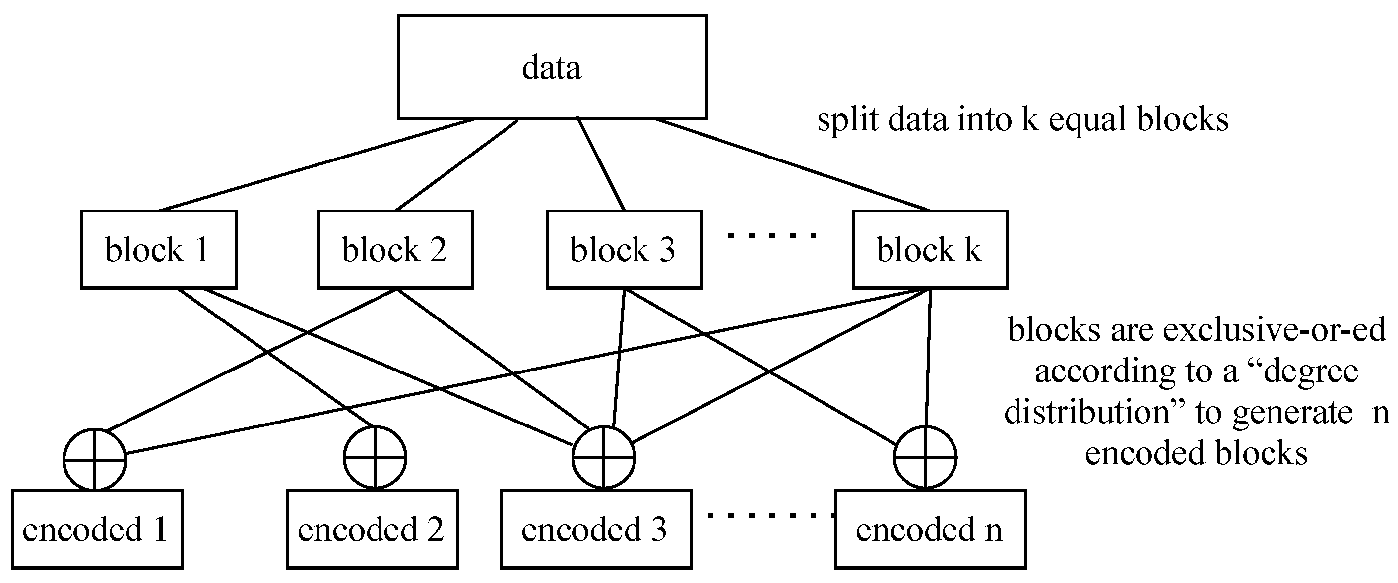
Erasure codes, specifically fountain codes, are rateless in the sense that they do not exhibit a fixed code rate but are adapted to the channel conditions. The original data are split into k equal blocks, and then encoded independently and randomly, according to a degree distribution which determines the number of blocks to be exclusive-or-ed into n encoded blocks using an maximum distance separable code [16]; this is referred to as the fountain code (see Figure 1). One of the properties of fountain coding is that the receiver can retrieve the original transport block (TB) from any subset () of encoded blocks; where . Thus, the decoder starts decoding the message once the first k encoded blocks are received using the sum–product algorithm [16]. If these blocks do not have enough information to retrieve the original message then the encoder has to wait for more encoded blocks.
In [13], we analytically derived the average latency using queuing theory by making the following assumptions:
- Purging scenario, that is, after k out of n encoded blocks are received, the other remaining encoded blocks are removed from the queues;
- The switch on the fronthaul has a negligible delay and hence the switch delay is not included in the fronthul latency budget.
In this paper, however, we implement the same model in a software defined radio-based testbed, while fixing the value of n to 4, given the hardware limitations, to experimentally evaluate the framework and provide numerical proof on its performance. Furthermore, in this paper, we attempt to overcome the constraints raised by assumptions taken in [13] as follows:
- Assess the impact of the proposed solution on end-to-end system performance: by executing the solution on a hardware testbed, we can ensure that the system is functioning properly by ensuring that user equipment remains synchronized with the network and maintains network connection, as well as that network resources, such as memory, storage space and queue buffers, are sufficiently available for executing the proposed solution;
- Packets are not removed from the fronthaul network; that is, after receiving k out of n encoded blocks, the remaining n − k encoded blocks are not removed from the fronthaul network and they will continue to be processed, which is more realistic;
- Consider internal process delay in the (CU + DU) entity: processing time including scheduling, queueing, encoding and packetizing data which might affect the performance of the system. The time taken depends, essentially, on capabilities of the hardware used and how functions are processed. In this experimental, function blocks are sequentially processed on a general purpose processor;
- Include switch queueing delay: the amount of time spent queuing at the switch aggregator to demonstrate the feasibility of aggregating traffic in the fronthaul network, resulting in more realistic latency measurements. The worst case scenario happens when all the n encoded blocks arrive at the switch aggregator at the same time. Such a scenario is very likely to occur when the n encoded blocks are serialised at the same time on n separate fronthaul paths with the same capacity;
- Include network driver delay: the amount of time it takes to send a packet onto a fronthaul network, which is subject to a queueing delay;
- Emulate traffic congestion on the fronthaul to account for scenarios with background traffic.
For the analysis, we continuously generate data in the (CU + DU) entity to be transmitted to the user equipment via the fronthaul. The experiment is repeated several times, then the average latency and the probability of being able to transmit a packet over the fronthaul within a latency deadline are measured.
3. Experimental Testbed & Evaluation Methodology
In this section we detail our experimental testbed and describe our evaluation methodology.
3.1. Implementation of Experimental Testbed
For our experimentation, we consider a long-term evolution system based on the Open Air Interface [17]. Our choice of the long-term evolution module is based on the availability of a reliable open source platform. Hence, user equipment, CU, DU, and RU are based on Open Air Interface implementation comprising full long-term evolution functionalities whereby the CU is collocated with the DU.
To exploit the concept of multi-path diversity with channel coding in the Cloud-RAN platform, we implemented further amendments in the Open Air Interface to:
- Decouple RAN functions between (CU + DU) entity and RU entity;
- Support channel coding in order to encode/decode data streams;
- Packetize/depacketize packets to transmit/receive them over the Ethernet-based fronthaul interface;
- Support the multiple Ethernet-based fronthaul by transmitting over multiple Ethernet ports, each connected to a separate Ethernet link.
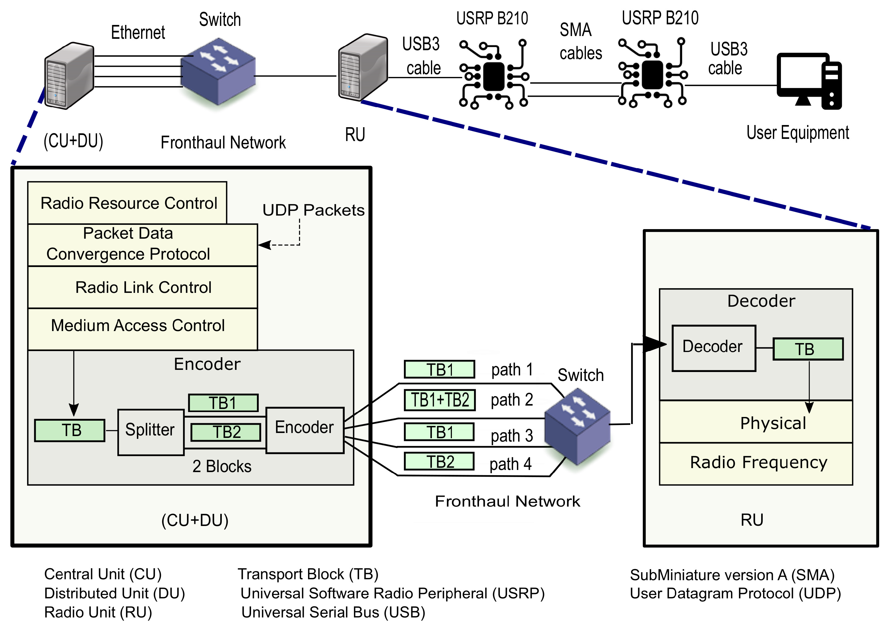
The experimental setup and data flow are shown in Figure 2. The (CU + DU) and the RU run on two separate servers each with 8 gigabytes of random access memory (RAM) with a Xeon 1220, and 4 cores. While the user equipment runs on a personal computer with 4 gigabytes of RAM with an Intel core i5. All hosts have a network interface card with a speed of 1 Gigabit and operate on Ubuntu 14 with a low latency kernel. The system operates on frequency division duplex on band 7 with 5 MHz bandwidth. The main configuration parameters are listed in Table 1; other Open Air Interface parameters are set to their default values.
The (CU + DU) entity accommodates MAC, Radio Link Control (RLC), Packet Data Convergence Protocol (PDCP) and Radio Resource Control functionalities, while PHY and Radio Frequency functionalities are located in the RU. The (CU + DU) entity is connected to 4 Ethernet fronthaul links each 3 meters long and with a capacity of 1 Gigabit. The four links are connected to a 1 Gigabit layer 3 switch that switches packets to the right port based on internet protocol addresses. The output port of the switch is connected via a 3 meter long Ethernet fronthaul, with a capacity of 1 Gigabit, to the RU. This latter is connected to the user equipment via Universal Serial Bus 3 cables and two Universal Software Radio Peripherals, which are responsible for transmitting and receiving radio frequency signals. The Universal Software Radio Peripherals are connected through SubMiniature version A cables of a 1 meter long. In this experimentation, the analysis is applied only to the downlink communication.
3.2. Evaluation Methodology
To evaluate the performance of the system, once the radio access bearers for the data flow are established, User Datagram Protocol (UDP) packets are injected as user data at every frame into PDCP at the (CU + DU) entity. PDCP, then, adds a PDCP header to the UDP packet then delivers it to RLC. RLC informs its buffer occupancy to MAC to determine the TB size. MAC then requests data from RLC and composes the TB. Thereafter, the TB is processed by the coding block. The coding block has two main blocks (Figure 2):
- Splitter which splits each TB into k = 2 equal blocks;
- Encoder that encodes the k blocks into n = 4 encoded blocks of the same size using fountain code and sends each encoded block into one of the n fronthaul paths.
The encoded blocks are then packetized to Ethernet packets and are transmitted to RU via a raw Ethernet socket over the fronthaul. The receiver can retrieve the original TB from any subset ≥ k of encoded blocks.
In this experiment, latency is measured as the round trip time (RTT) of one packet from the MAC to the PHY layer. Procedures involved in the measurement of RTT are summarized in Algorithm 1.
| Algorithm 1 Round trip time (RTT) measurement |
|
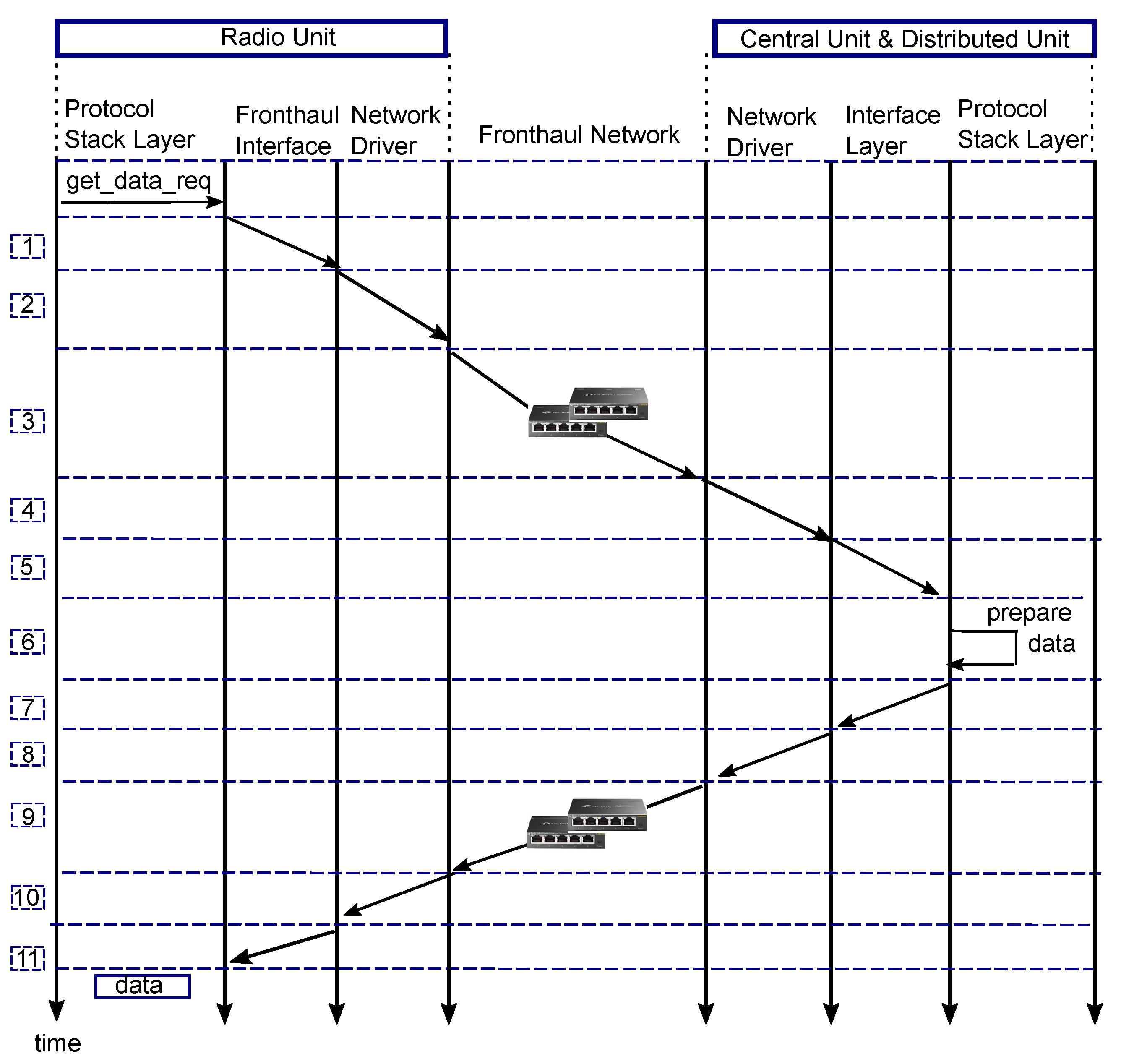
Figure 3 shows a simplified representation of events and entities included in the measurement of RTT. Mathematically, the RTT of one sample can be expressed as:
latency(1), latency(7) is the time that the fronthaul interface takes to packetize data and write the packet descriptor onto the network driver transmit queue.
latency(2), latency(8) is the time taken for the network driver to fetch the packet and launch it onto the fronthaul network. Since packets are fetched one by one from the transmit queue, this latency is subject to a queueing delay.
latency(3), latency(9) is the time to transport data on the fronthaul network and is given by:
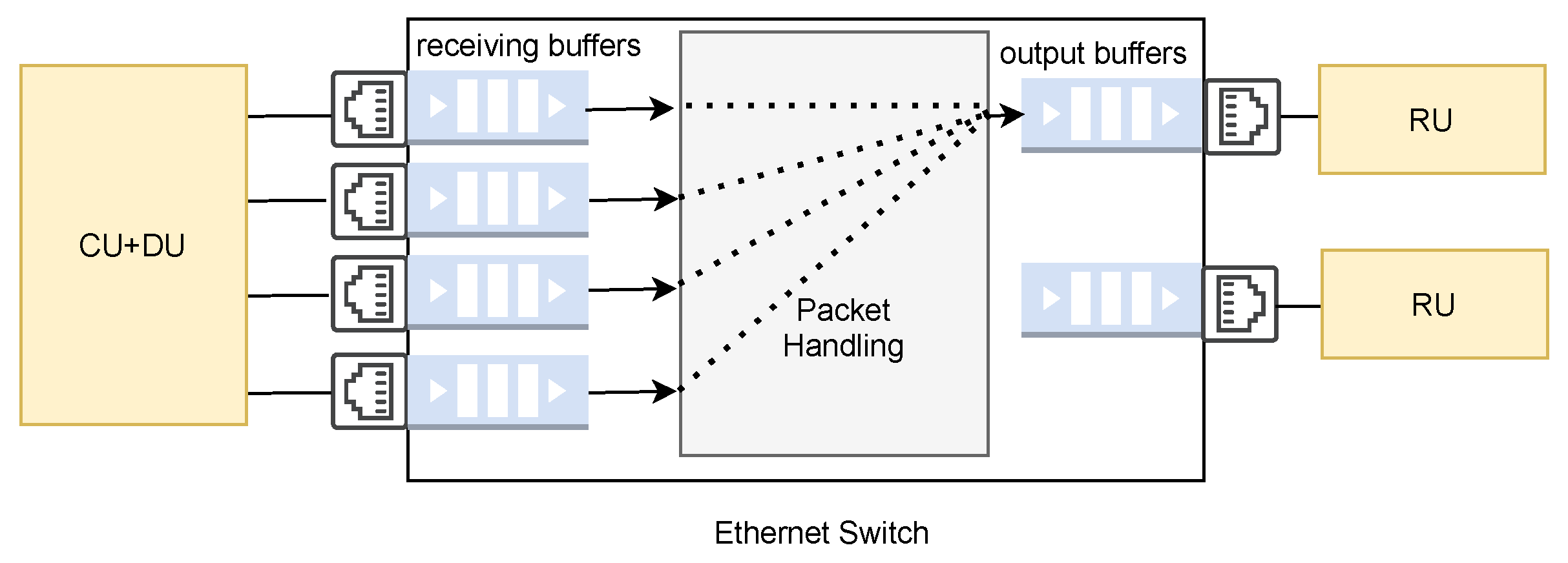
where is the transmission time, that is, the time taken to transmit a packet over a fronthaul link and is defined as the packet size over the bit rate of the fronthaul link, is the propagation time, that is, the time taken for a packet to propagate between two nodes. The propagation time is calculated by the distance over propagation speed in the fronthaul. is the number of fronthaul segments between the (CU + DU) entity and the RU entity, is the amount of time the switch requires to process a packet for routing (encapsulation/decapsulation and table lookup) and is the queueing delay in a switch when there is a contention at its ports. Figure 4 shows that 4 fronthaul paths are input to the switch, all of which must be directed to the same destination, that is, RU. Therefore, packets may encounter queueing delay at the switch. Therefore, 0 and there is one switch in the experimental setup, hence = 1 in Equation (2).
latency(4), latency(10) time taken for network driver to write packet descriptor in the queue. This latency is subject to a queueing delay when multiple data are sent over the Ethernet sockets.
latency(5), latency(11) is the time that the fronthaul interface takes to read data from the network driver queue and depacketize data by removing the Ethernet header from the packet.
latency(6) is the protocol stack processing time of the request at the (CU + DU) entity to prepare data. This latency depends on the processing capability of the central processing unit.
The average latency of RTT is computed as:
where N is the number of RTT samples collected during the execution of the experimental test.
4. Analysis of the Experimental Results
In this section, the performance of the system is evaluated by evaluating the results of the fronthaul latency, jitter, and probability of error. How these quality metrics meet the requirements of the 3GPP are also evaluated. The 3GPP specifies that the maximum allowed one-way latency for the MAC–PHY split (Option 6 according to 3GPP terminology) should be 250 s (Table A-1 in [14]). The maximum allowed average RTT latency, therefore, is 500 s (). Since RTT in this experiment is measured as stated in Section 3.2, the analysis considers 500 s as the maximum acceptable latency on the fronthaul.
4.1. Analysis of Latency and Jitter for MPC
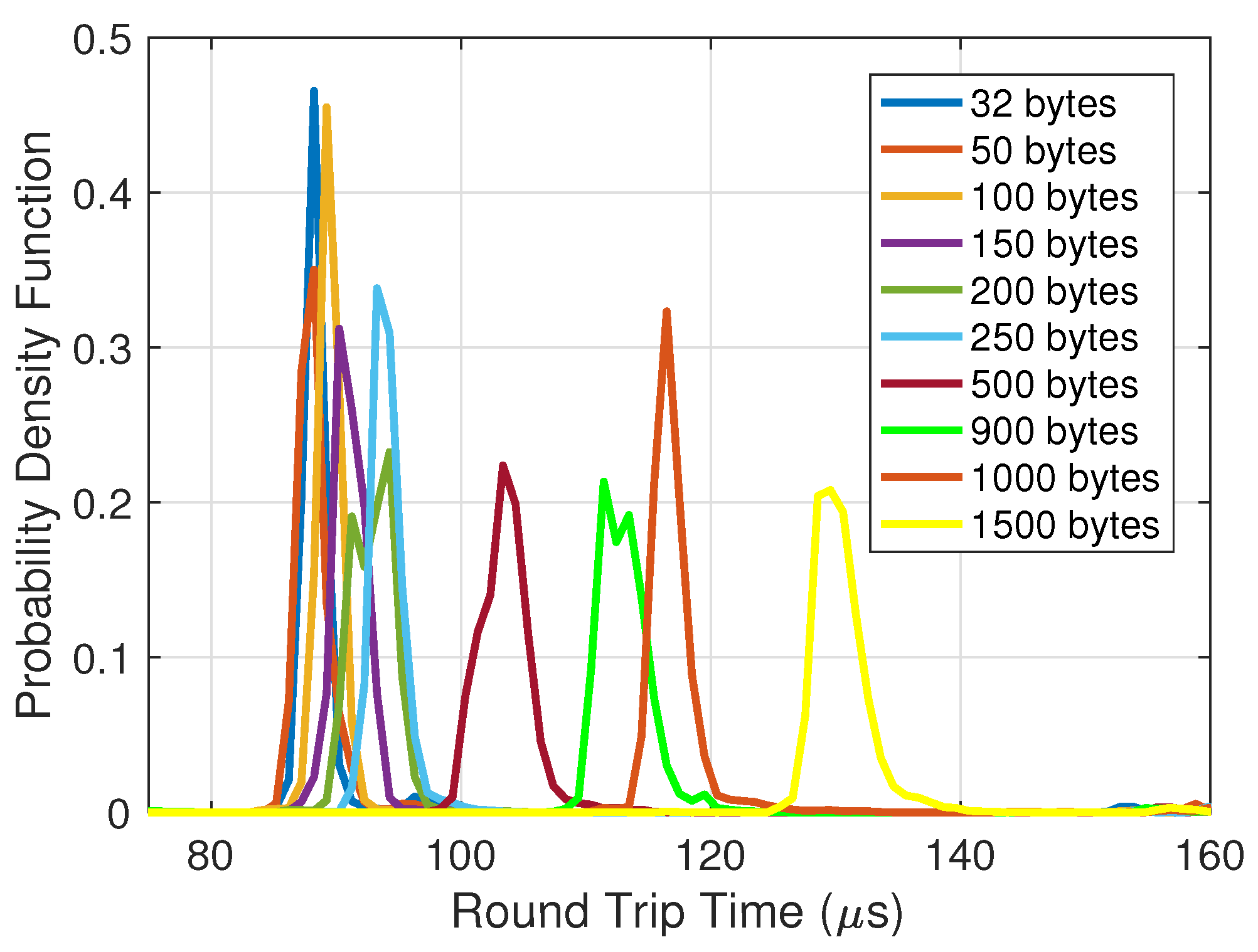
In the first experiment, the performance of MPC is evaluated in terms of latency and jitter. The performance is evaluated for scenarios with packet sizes of 32 bytes up to 1500 bytes to cover both URLLC and enhanced mobile broadband 5G classes to understand how the packet size impacts the fronthaul latency. UDP packets, thus, with different sizes, are injected into the PDCP layer in the (CU + DU) entity in every frame. The protocol stack processes the packet then the MAC encodes it to encoded blocks and transmits them on the fronthaul. The latency is measured as the RTT as explained in Section 3.2. The percentiles and probability density function results of the RTT are shown in Figure 5 and Figure 6, respectively.
Figure 5 shows the results for different percentile values of the latency as a function of UDP packet size. In general, as the UDP packet size increases, the percentile values of latency increase too; this is because larger packets take longer to be processed. The RTT for a packet size of 100 bytes is, however, less than that for the 32 bytes and 50 bytes packet sizes. The reasoning behind this behaviour is that the packets of 32 bytes and 50 bytes are split by the coding block in the (CU + DU) entity to 16 bytes and 25 bytes, respectively. Even when the overhead header is added, the two packet sizes are still less than the minimum 64 bytes of the Ethernet frames. Therefore, prior to transmitting these packets, padding is added by the Ethernet network card, which adds an extra delay to their RTT.
Figure 5 shows that MPC provides promising results, as 95th percentile values remain below the maximum acceptable fronthaul latency for the MAC–PHY split. Figure 5 also shows that the 25th, 50th and 95th percentile values are of low variability as they are close to each other. The difference between the 95th and 25th values is 8 s.
Focusing on the 50th percentile result, if the packet size is less than 500 bytes, the increase in latency is low and is around from the packet size of 32 bytes to the packet size of 250 bytes. On the contrary, with packet sizes larger than 500 bytes, the increase in latency is for a packet 3 times larger than 500 bytes. Ssuch behaviour can be observed in Figure 6, whereby the probability density distributions of packet sizes from 32 bytes to 250 bytes are very close to each other. However, for packet sizes ranging from 500 bytes to 1500 bytes, the probability density distributions are further apart. Another observation from Figure 6 is that the standard deviation increases with the size of the packet. For example, for packets of size 1500 bytes, the deviation is s, which is approximately two times as large as for packets of size 32 bytes. This indicates that the larger the packet size, the higher the variations in the processing time of the protocol stack, encoder/decoder and transport network. This plot provides insight into how to choose the packet size to be transmitted on the fronthaul. For example, if the probability density distribution of the latency for a service should have a deviation of less than 8 s, then the choice of packet size would satisfy the requirement. It can be concluded from Figure 5 and Figure 6 that the average latency complies with the requirements of 3GPP, that is, staying below 250 s [14].
Further analysis of jitter can be found in Figure 7. Two factors primarily introduce jitter: (i) the packet switch network, which can introduce variation into the packet delay when processing packets; (ii) the operating system, whereby the variation of system daemons and interrupts results in jitter. From Figure 7, it can be seen that the distribution of jitter remains the same for different packet sizes and is just below 2 s. The tail latency of Figure 7 shows that latency values greater than s have a very low probability that is close to zero.
4.2. Comparison of MPC and Multi-Path Fronthaul with Duplication (MPD)
The second experiment compares the performance of MPC to that of the baseline MPD, which replicates the same data stream across multiple fronthaul paths. In particular, the analysis evaluates how the probability of error is improved by either of these two schemes and what the impact on the latency is. In this experiment, the focus is on the URLLC service, particularly on the tactile interaction in which reliability with low latency are key aspects. The payload sizes of the tactile interaction are typically ≤256 bytes and the error probability requirement is [18].
Fixed UDP packets of a size of 120 bytes are injected in PDCP in every frame. The probability of error vs latency function is presented in Figure 8, where the probability of error is defined as the probability that the measured RTT latency exceeds a predefined latency deadline t, mathematically expressed as: . This probability of error represents the packet error rate due to the fact that some packets arrive late or never arrive due to factors such as buffer overflows, queueing, and so on.
It can be seen that, for latency values less than s, the performance of MPC and MPD is generally the same. However, as latency increases to higher than s, MPC delivers a lower error probability. MPC can achieve a latency reduction of 73 s, with respect to MPD at the error probability of . It is interesting to look specifically at the performance at the latency of s, which is the maximum acceptable RTT latency on the fronthaul for the MAC–PHY split [14]. At this point, shown by the vertical black line in Figure 8, MPC clearly outperforms MPD and can achieve an error probability of at 288 s latency, leaving a margin of 212 s to the maximum allowed RTT. Therefore, MPC is set to benefit from both diversity and the splitting of packets into smaller blocks.
With MPC reaching an error probability of at a lower latency than MPD, a larger gap to the maximum allowed RTT can be gained. This gain can be beneficial for fronthaul dimensioning by allowing the distance between the (CU + DU) and the RU entities to be increased. The fronthaul distance can be extended by , where is the time gap to the maximum allowed RTT, is the propagation delay in the Ethernet, which is 5 s per km [19] and 2 accounts for the round trip. In our setup, for example, given that = 212 s at an error probability of for MPC (see Figure 8), the fronthaul can be extended by km.
Now, the performance of multi-path fronthaul is evaluated by emulating the delay in the fronthaul transport. In our next experiment, a delay is added to the fronthaul path 2 to emulate traffic congestion. An additional delay on path 2 will clearly affect the delivery of important information since link 2 carries the information required for decoding data. To investigate whether the delay would affect the performance of MPC due to the waiting effect described in Section 2, the network delay is emulated by using NetEM to add a normal distribution delay of s s. Figure 9 shows the probability of error as a function of the latency. It can be seen that MPD and MPC start with the same probability of error, but after latency exceeds s, the performance of the two schemes alternates. However, MPD outperforms MPC at an error probability of . Thus, in this case, where the extra delay is simulated in path 2, MPC is more affected than MPD because MPC needs to wait for more encoded blocks to be received to successfully decode the blocks. Here again, taking the maximum acceptable RTT latency of s on the fronthaul for the MAC–PHY split [14], which is shown by the vertical black line in Figure 9, MPC can achieve an error probability of at latency 158 s earlier than the maximum allowed RTT.
Aside from the benefit of MPC in enhancing reliability while the latency remains below a strict latency bound, another aspect to consider is the load on the fronthaul network introduced by MPC and MPD. For each data point of size S bits, MPD duplicates a full copy of the data into n blocks of size S bits. On the other hand, an MPC encodes the data into n blocks of size bits. For example, if 1 packet of size S bits is to be transmitted every t milliseconds on average, the load on the fronthaul generated by MPC and MPD, denoted as and respectively, can be calculated as:
Equation (4) demonstrates the potential benefits of MPC over MPD in reducing the load on the fronthaul network, allowing for a significant reduction in the required bandwidth by a factor of k (), resulting in a reduction in fronthaul cost.
The results obtained under the particular system parameters set out in this paper show that MPC performs well despite the delay that is introduced into the fronthaul network. The budget latency, however, can be lowered by considering some aspects of the experiment deployed in Section 3, such as the deployment of specific devices such as accelerators for the encoder/decoder and RAN functions that are computationally intensive, and the use of the Data Plane Development Kit for fast packet processing.
5. Conclusions
This paper validates the Cloud-RAN model with the split between MAC and PHY over Ethernet with additional reliability using MPC. As proof-of-concept for the proposed solution, we present an end-to-end Cloud-RAN testbed that integrates user equipment, RU, DU, CU, and a fronthaul network. We first analyse the performance of MPC in terms of latency and jitter using different packet sizes. The results were satisfying in terms of average RTT latency being compliant with the requirements of 3GPP, that is, staying below s. From the latency constraint perspective, the findings in this chapter demonstrate how the size of the packet has a significant effect on RTT. To lower the RTT, it is very important to choose the right size of the packet.
Then, we compared the performance of MPC with MPD from a probability of error perspective. The experimental results show that MPC achieved an error probability of at a latency lower than MPD, that is, a latency reduction of 73 s. However, when one of the paths is simulated with an extra delay, MPC achieved an error probability of at a latency s later than MPD. Nevertheless, MPC can deliver an error probability of while staying below the acceptable latency on the fronthaul for the MAC–PHY split, in addition to the advantage of MPC over MPD in terms of reducing fronthaul load. The results obtained in this paper are consistent with the results reported in [12,13] in validating the effectiveness of MPC, opening the possibility to implement MPC as a means of improving reliability in a Cloud-RAN system.
The deployment described in this paper is an experimental facility that may easily be expanded to a larger scale testbed in terms of network architecture, fronthaul network topology, and system traffic load.
Author Contributions
G.M. is the primary author; T.M. contributed in terms of problem formulation, providing ideas, and writing. Both authors have read and agreed to the published version of the manuscript.
Funding
This work has been partially supported by the EU H2020 Primo-5G project. Additional support for this research is received form The Engineering and Physical Sciences Research Council (EPSRC) industrial Cooperative Awards in Science & Technology (iCASE) award and from BT and the EPSRC infrastructure grant, INITAITE ().
Data Availability Statement
Not Applicable, the study does not report any data.
Conflicts of Interest
The authors declare no conflict of interest.
References
- NGMN. 5G RAN CU—DU Network Architecture, Transport Options and Dimensioning; White Paper; Version 1.0; NGMN: Frankfurt am Main, Germany, 2019. [Google Scholar]
- Condoluci, M.; Mahmoodi, T. Softwarization and virtualization in 5G mobile networks: Benefits, trends and challenges. Comput. Netw. 2018, 146, 65–84. [Google Scholar] [CrossRef] [Green Version]
- Miroslaw, K. Latency-Aware DU/CU Placement in Convergent Packet-Based 5G Fronthaul Transport Networks. Appl. Sci. 2020, 10, 7429. [Google Scholar]
- Yusupov, J.; Ksentini, A.; Marchetto, G.; Sisto, R. Multi-Objective Function Splitting and Placement of Network Slices in 5G Mobile Networks. In Proceedings of the 2018 IEEE Conference on Standards for Communications and Networking (CSCN), Paris, France, 29–31 October 2018; pp. 1–6. [Google Scholar] [CrossRef]
- Mountaser, G.; Condoluci, M.; Mahmoodi, T.; Dohler, M.; Mings, I. Cloud-RAN in Support of URLLC. In Proceedings of the 2017 IEEE Globecom Workshops, Singapore, 4–8 December 2017. [Google Scholar] [CrossRef]
- Hadi, M.U.; Awais, M.; Raza, M. Multiband 5G NR-over-Fiber System Using Analog Front Haul. In Proceedings of the 2020 International Topical Meeting on Microwave Photonics (MWP), Virtual Conference, Online. 24–26 November 2020; pp. 136–139. [Google Scholar]
- Hadjer, T.; Hind, C.-T.; Badii, J.; Sara, A. Split analysis and fronthaul dimensioning in 5G C-RAN to guarantee ultra low latency. In Proceedings of the 2020 IEEE 17th Annual Consumer Communications & Networking Conference, Las Vegas, NV, USA, 10–13 January 2020; pp. 1–4. [Google Scholar]
- ORAN-WG4. Control, User and Synchronization Plane Specification. Available online: https://www.o-ran.org/blog/2020/6/29/23-new-o-ran-specifications-have-been-released-in-the-first-half-of-2020 (accessed on 29 June 2021).
- CPRI. eCPRI Interface Specification. Interface Specification, Common Public Radio Interface, 2019. V2.0. Available online: http://www.cpri.info/downloads/eCPRI_v_2.0_2019_05_10c.pdf (accessed on 29 June 2021).
- Khosravirad, S.R.; Viswanathan, H.; Yu, W. Exploiting Diversity for Ultra-Reliable and Low-Latency Wireless Control. IEEE Trans. Wirel. Commun. 2021, 20, 316–331. [Google Scholar] [CrossRef]
- Belschner, J.; Michalopoulos, D.S. A Hybrid Approach for Data Duplication and Network Coding. In Proceedings of the 2019 European Conference on Networks and Communications (EuCNC), Valencia, Spain, 18–21 June 2019; pp. 369–373. [Google Scholar] [CrossRef] [Green Version]
- Park, S.H.; Simeone, O.; Shamai, S. Robust Baseband Compression Against Congestion in Packet-Based Fronthaul Networks Using Multiple Description Coding. Entropy 2019, 21, 433. [Google Scholar] [CrossRef] [PubMed] [Green Version]
- Mountaser, G.; Mahmoodi, T.; Simeone, O. Reliable and Low-Latency Fronthaul for Tactile Internet Applications. IEEE JSAC 2018, 36, 2455–2463. [Google Scholar] [CrossRef] [Green Version]
- 3GPP. Radio Access Architecture and Interface (Release 14); Technical Report 38.801. Available online: https://portal.3gpp.org/desktopmodules/Specifications/SpecificationDetails.aspx?specificationId=3056 (accessed on 29 June 2021).
- Brown, G. New Transport Network Architectures for 5G RAN. White Paper. Available online: https://www.fujitsu.com/us/Images/New-Transport-Network-Architectures-for-5G-RAN.pdf (accessed on 29 June 2021).
- Cui, M.; Zhang, H.; Huang, Y.; Xu, Z.; Zhao, Q. A Fountain-Coding Based Cooperative Jamming Strategy for Secure Service Migration in Edge Computing. Wirel. Netw. 2021. [Google Scholar] [CrossRef]
- Nikaien, N. OpenAirInterface Simulator Emulator. White Paper. 2015. Available online: https://openairinterface.org/docs/oai_oaisim_desc.pdf (accessed on 29 June 2021).
- 3GPP. Technical Specification Group Services and System Aspects; Service Requirements for the 5G System; Stage 1 (Release 16). Technical Report 22.261. 2018. Available online: https://portal.3gpp.org/desktopmodules/Specifications/SpecificationDetails.aspx?specificationId=3107 (accessed on 29 June 2021).
- Prytz, G. A performance analysis of EtherCAT and PROFINET IRT. In Proceedings of the 2008 IEEE International Conference on Emerging Technologies and Factory Automation, Hamburg, Germany, 15–18 September 2008; pp. 408–415. [Google Scholar] [CrossRef]
Figure 1.
Schematic diagram of an fountain code. The blocks are encoded into n encoded blocks using a given degree distribution.
Figure 1.
Schematic diagram of an fountain code. The blocks are encoded into n encoded blocks using a given degree distribution.

Figure 2.
End-to-end system experimental setup for multi-path fronthaul with erasure coding (MPC) for downlink communication with medium access control (MAC) and physical (PHY) layer split, with an illustration of data encoding in the (CU + DU) entity and decoding in the RU entity.
Figure 2.
End-to-end system experimental setup for multi-path fronthaul with erasure coding (MPC) for downlink communication with medium access control (MAC) and physical (PHY) layer split, with an illustration of data encoding in the (CU + DU) entity and decoding in the RU entity.

Figure 3.
Representation of the round trip time measurement.

Figure 4.
Switch internal architecture.

Figure 5.
Percentile of latency on the Ethernet-based multi path fronthaul as a function of different packet sizes.
Figure 5.
Percentile of latency on the Ethernet-based multi path fronthaul as a function of different packet sizes.

Figure 6.
Distribution of latency on the Ethernet-based multi path fronthaul as a function of different packet sizes.
Figure 6.
Distribution of latency on the Ethernet-based multi path fronthaul as a function of different packet sizes.

Figure 7.
Distribution of jitter on the fronthaul for different packet sizes.

Figure 8.
Probability of error vs latency function for multi-path fronthaul with erasure coding (MPC) with k = 2 and multi-path fronthaul with duplication (MPD). The dashed line represents the maximum latency to be supported by the MAC–PHY split.
Figure 8.
Probability of error vs latency function for multi-path fronthaul with erasure coding (MPC) with k = 2 and multi-path fronthaul with duplication (MPD). The dashed line represents the maximum latency to be supported by the MAC–PHY split.

Figure 9.
UDP latency functions for MPC with k = 2 and MPD when adding a delay to fronthaul path 2. The dashed line represents the maximum latency to be supported by the MAC–PHY split.
Figure 9.
UDP latency functions for MPC with k = 2 and MPD when adding a delay to fronthaul path 2. The dashed line represents the maximum latency to be supported by the MAC–PHY split.


Table 1.
Open Air Interface parameters.
| Parameters | Values |
|---|---|
| Carrier Frequency | 2.68 GHz |
| System Bandwidth | 5 MHz |
| Frame Type | Frequency Division Duplex |
| Radio Frequency frontend | 1 transmit antenna/1 receive radio frequency |
| Modulation | Adaptive Quadrature Amplitude Modulation (QAM): QAM, 16 QAM and 64 QAM) |
| Packet Size | 32–1500 bytes |
| Fronthaul Capacity | 1 Gigabit per second |
Publisher’s Note: MDPI stays neutral with regard to jurisdictional claims in published maps and institutional affiliations. |
© 2021 by the authors. Licensee MDPI, Basel, Switzerland. This article is an open access article distributed under the terms and conditions of the Creative Commons Attribution (CC BY) license (https://creativecommons.org/licenses/by/4.0/).
Share and Cite
MDPI and ACS Style
Mountaser, G.; Mahmoodi, T. An SDR-Based Experimental Study of Reliable and Low-Latency Ethernet-Based Fronthaul with MAC-PHY Split. Future Internet 2021, 13, 170. https://0-doi-org.brum.beds.ac.uk/10.3390/fi13070170
AMA Style
Mountaser G, Mahmoodi T. An SDR-Based Experimental Study of Reliable and Low-Latency Ethernet-Based Fronthaul with MAC-PHY Split. Future Internet. 2021; 13(7):170. https://0-doi-org.brum.beds.ac.uk/10.3390/fi13070170
Chicago/Turabian StyleMountaser, Ghizlane, and Toktam Mahmoodi. 2021. "An SDR-Based Experimental Study of Reliable and Low-Latency Ethernet-Based Fronthaul with MAC-PHY Split" Future Internet 13, no. 7: 170. https://0-doi-org.brum.beds.ac.uk/10.3390/fi13070170
Note that from the first issue of 2016, this journal uses article numbers instead of page numbers. See further details here.