Effects of Pitch-Based Short Carbon Fibers on the Workability, Unit Weight, and Air Content of Mortar Composite

1
Angelo Del Zotto School of Construction Management, George Brown College, 146 Kendal Avenue, Toronto, ON M5T 2T9, Canada
2
Department of Civil Engineering, Faculty of Engineering and Architectural Science, Ryerson University, 350 Victoria Street, Toronto, ON M5B 2K3, Canada
3
Department of Civil and Environmental Engineering, Faculty of Engineering, University of Windsor, 401 Sunset Avenue, Windsor, ON N9B 3P4, Canada
*
Author to whom correspondence should be addressed.
Fibers 2018, 6(3), 63; https://0-doi-org.brum.beds.ac.uk/10.3390/fib6030063
Submission received: 15 July 2018
/
Revised: 22 August 2018
/
Accepted: 27 August 2018
/
Published: 30 August 2018
(This article belongs to the Special Issue Carbon Fiber Reinforced Composites)
Abstract
:Pitch is a viscoelastic polymer material consisting of aromatic hydrocarbons. It is used to produce carbon fibers with sheet-like crystal structures. The aim of the work presented in this paper was to evaluate the effects of pitch-based short carbon fibers on the workability, unit weight, and air content of freshly mixed mortar composite. Experimental investigation was carried out on five different types of mortar composite, including a control mortar. Four mortar composites were prepared including pitch-based short carbon fibers with 1–4% volume contents. The fresh mortar composites were tested to determine their slump, inverted slump cone flow (flow time, mass flow, and volume flow), unit weight, and air content. In addition, the correlation between the slump and flow time of various mortar composites was determined. It was found that the slump decreased with the increasing volume content of carbon fibers. The flow time of mortar composite increased, and therefore its mass flow and volume flow decreased with a greater volume content of carbon fibers. The slump was strongly correlated with the flow time, with a correlation coefficient of 0.9782. Furthermore, the unit weight of the fresh mortar composite decreased due to the incorporation of carbon fibers. However, amongst the different carbon fiber reinforced mortar composites, the mortar with 3% fiber volume content provided the highest unit weight. The air content results were consistent with the unit weight results. The change in air content of various mortar composites followed a trend reciprocal to that of unit weights. When the overall effects of carbon fibers were compared, it was observed that the fiber volume content higher than 3% resulted in a significantly low workability and provided a much lower unit weight with greater entrapped air content.
Keywords:
air content; carbon fibers; fiber content; mix proportions; mortar; unit weight; workability1. Introduction
Mortar and concrete are cement-based composite materials or cement composites. The use of short fibers in cement composites is not new. Different types of short fiber have been used in cement composites [1,2,3,4,5]. The first widely used fiber reinforced composite was asbestos cement in which asbestos fibers were incorporated [6]. Thereafter, the other varieties of fiber have been used to produce cement composites. Amongst these, conventional fibers, such as glass fibers [7] and steel fibers [4], and synthetic fibers, such as polypropylene fibers [5] and cellulose fibers [8] are noteworthy. The reinforcement with asbestos fibers helped the construction industry for many years, especially in thin sheet applications. Unfortunately, the asbestos fibers were found to cause fibrosis (asbestosis) and two other forms of lung cancer [9], and led to a quest for alternative fibers, which are medically as well as environmentally safe and sound. Attempts were made with glass, cellulose, and steel fibers, but they seemed to be discouraging due to durability problems. The embrittlement and strength loss of glass fibers [10], the moisture sensitivity of cellulose fibers [11], and the corrosion of steel fibers [12] steered the construction industry to find durable fibers, which are also medically and environmentally safe.
Carbon fibers became very attractive for cement composites because of their superior chemical stability at ambient temperatures. They are inert, medically safe, physically as strong as steel fibers, and chemically more stable than glass fibers in an alkaline environment. Besides, carbon fibers are lighter and their strength to density ratio is higher than the other fibers. Historically, polyacrylonitrile (PAN)-based carbon fibers were used first to produce fiber reinforced cement composites [13]. The drawback of this type of carbon fibers was their high cost, but the development of short pitch-based carbon fibers has compensated this shortcoming. Pitch-based carbon fibers are considered an excellent reinforcement for cement composites, and they have been extensively used for general applications due to lower price [14,15,16,17,18,19]. The use of carbon fibers in mortar may offer many advantages such as lower unit cost, light weight, reduced shrinkage, and better rheological behavior in companion with excellent mechanical properties. This study used randomly oriented, short pitch-based carbon fibers in cement mortar and monitored their performance at different fiber contents, particularly for the freshly mixed mortar mixes.
The present study examined several key physical and workability properties of normal Portland cement mortar (NPCM, control mortar) and various fresh carbon fiber reinforced mortars (CFRMs). The mortars were prepared with 0–4% carbon fiber contents and tested for workability, unit weight, and air content. The workability was measured with respect to slump and inverted slump cone flow (flow time, mass flow, and volume flow). The experiments were conducted to examine the effects of different volume contents of carbon fibers on the aforementioned properties. The experimental results revealed the effects of short carbon fibers on the workability, unit weight, and air content of mortar composite. Based on the obtained test results, the optimum carbon fiber content was also specified in order to produce CFRM.
2. Research Significance
The incorporation of carbon fibers into cement composites makes them lightweight and suitable for applications in the buildings in the form of wall cladding or wall panels. However, the use of short carbon fibers in cement composites is quite challenging due to the mixing and workability problems encountered for the fresh composite mixes. Those drawbacks have been resolved in the present study using silica fume and relatively a high dosage of superplasticizer that facilitated the dispersion of carbon fibers in the fresh mortar mixes without forming any fiber balls. In the present study, comparatively high amounts of short carbon fibers were used without any visible mixing and workability issues. This is the main research contribution of the present study. The other significant contribution of this study is the use of the modified inverted slump cone flow test to measure the workability characteristics of CFRMs and establish a correlation with the results of the traditional slump test. Above all, the optimum carbon fiber content was deduced in the context of the key fresh properties of mortar composite.
3. Materials and Methods
3.1. Materials Selection
Sand, normal Portland cement, compacted or densified silica fume, pitch-based short carbon fibers, tap water, and superplasticizer (high-range water-reducing admixture) were used in the present study to prepare different mortar composites.
Locally available natural river sand (S) was used as fine aggregate. It was free from deleterious materials. The important physical properties of sand are given in Table 1. The sieve analysis of sand was carried out in accordance with ASTM C33/C33M-16 [20]. The sieve analysis results of sand are shown in Table 2.
Normal Portland cement (C) was used as the main cementing material. It complied with the standard specification for ASTM Type I Portland cement [21]. The specific gravity of cement was 3.15. The chemical composition of cement is shown in Table 3.
Densified silica fume (SF) was used as a partial replacement for cement. It complied with the ASTM standard specification for silica fume [22]. Silica fume and cement together were considered as the total binder (B). The specific gravity of silica fume was 2.20. The chemical composition of silica fume is shown in Table 4.
Pitch-based short carbon fibers (CFs) were used in the present study. They were available in black chopped strands of multi-filaments sized with 1–2% water-soluble resin. The fibers were 10 mm long and had a filament diameter of 17 μm. The fibers were insoluble in water and their elemental carbon content was about 98 to 99%. Some of the major physical properties of carbon fibers are given in Table 5.
Normal tap water (W) was used for mixing and curing purposes. The quality of this water conformed to the requirements as mentioned in the ASTM standard specifications for ready-mixed concrete [23]. In general, the water quality was excellent for use in producing the fresh mortars. It did not contain any objectionable substances causing color or odor. The total amount of dissolved solids in water was 18 mg/L. The density of water considered in the mix design calculations for various mortar composites was 1000 kg/m3.
A naphthalene based superplasticizer (SP) was used to control the workability of the fresh mortars. It was a dark brown liquid cement-dispersing agent. It did not contain any chloride and it was 100% soluble in water. According to the ASTM standard specifications for chemical admixtures [24], it complied with Type F high-range water reducing admixture. The specific gravity and solid content of superplasticizer was 1.20 and 40%, respectively.
3.2. Mix Proportions of Mortar Composites
In total, one control mortar and four different types of CFRM mixes were designed with a water-binder ratio of 0.35 and a sand-binder ratio of 0.50. The control mix was normal Portland cement mortar and coded as NPCM, whereas the carbon fiber reinforced mortars containing 1%, 2%, 3%, and 4% fibers by volume were coded as CFRM1, CFRM2, CFRM3, and CFRM4, respectively. In all mortar mixes, silica fume was used substituting 15% of cement by weight.
The mix proportions of different mortar composites were decided monitoring the performance of the trial mixes. The acceptability of the trial mixes was examined by observing their workability. The workability of the trial mixes was maintained in such a way so that the inverted slump cone flow time of the fresh composite stayed below 30 s. In determining the mix proportions, cement together with silica fume was considered as the binder, and the amounts of silica fume and superplasticizer were determined based on the total amount of binder.
The proportions of different constituent materials were obtained based on the absolute volume method. The absolute volumes of sand, cement, silica fume, water, carbon fibers, and air voids were considered in the mix design calculations. In contrast, the amount of superplasticizer was not considered while computing the mix proportions, as it was incorporated in each mix as an additive to improve the workability of mortar composite. As a rule of thumb, 1% air content was considered for the control plain mortar, whereas 4% air content was assumed for the mortar with 1% carbon fibers (CFRM1). In CFRMs other than CFRM1, the increase in air content was assumed based on the increase in the volume content of carbon fibers (roughly 1% increase in air content for each 1% increase in fiber content). The mix proportions of the various mortars are summarized in Table 6.
Water corrections were made for all mortar mixes considering the water contributed by superplasticizer and the water absorbed by sand. Accordingly, the proportions of sand and water were adjusted based on the water corrections.
3.3. Preparation of Mortar Composite Mixes
The mortar mixes were produced based on the mix proportions shown in Table 6. For each mortar mix, two batches were prepared. Therefore, there were 10 batches in total for five different types of mortar mix. The quantity of fresh mortar considered for each batch was at least 15% more than the required. The amounts of component materials required for each batch were calculated, then the component materials were weighed and mixed at the ambient conditions to produce the fresh mortar composites.
The constituent materials were mixed in a pan-type mixer having a capacity of 0.1 m3. The overall mixing time was 6 min, except for the control mix; the mixing time for the control mortar was 4 min. The mixing procedure was established monitoring the behavior of the trial mixes. The use of a pan-type mixer induced more shear on the constituent materials of the mortar composite. Also, the addition of a relatively high dosage of superplasticizer resulted in a fluid mortar mix before incorporating carbon fibers. This process was helpful to avoid any mixing problem when carbon fibers were added in the mixer to mix with the other constituents of mortar. Based on the overall observations for the trial mixes, the following mixing sequence was used in preparing the fresh mortar composites:
- Sand, cement, and silica fume were charged first into the mixer and then mixed with half of the mixing water for 1 min.
- Superplasticizer was mixed with the remaining half of the mixing water in a separate container simply by stirring, and then the entire liquid mixture of water and high-range water-reducing admixture was added gradually into the running mixer within 1 min.
- The mixing was continued for additional 1 min.
- Carbon fibers were hand-sprinkled in the running mixer gradually within 2 min in the case of CFRMs (this step was omitted for the control mortar, NPCM).
- Lastly, the mixing of all component materials of mortar composite was continued for an additional 1 min.
3.4. Testing of Fresh Mortar Composites
The fresh mortar composites were sampled for testing slump, inverted slump cone flow (flow time, mass flow, and volume flow), unit weight, and air content. The sampling was conducted in accordance with ASTM standard practices [25].
3.4.1. Slump Test
The slumps of the fresh mortar composites were measured using a slump cone as specified in ASTM C143/C143M-16 [26]. A sample of freshly mixed mortar was placed in the slump cone. In the case of the control mortar (i.e., NPCM), the slump cone was filled at one time and no compaction was required, as it was in a highly fluid state. In the case of CFRMs, the fresh mortar was poured into the slump cone in three layers and each layer was compacted by rodding in a specified manner (25 strokes all over the surface). The slump cone was then lifted vertically without any disturbance and the mortar was allowed to subside. The distance between the centers of the original and subsided top surfaces was measured and reported as the slump of the mortar composite.
3.4.2. Test for Unit Weight and Air Content
The unit weight and air content of the freshly mixed mortar composites were determined according to ASTM C138/C138M-16 [27], with some exceptions for the highly fluid control mortar. A cylindrical measure was used in this test. The measure was calibrated before using in the test to know its volume capacity. The empty measure was also weighed before starting the test. A sample of the freshly mixed mortar composite was poured into the cylindrical measure in three layers. Each layer was compacted by vibration using a vibration table. The measure was filled in one layer and no vibration was used in the case of NPCM, because this mortar was self-compacting. The top surface of the mortar was leveled and the measure including the sample was then weighed. Later the weight of the fresh mortar composite placed in the cylindrical measure was determined. This weight was divided by the volume of the cylindrical measure to know the weight of the fresh mortar composite. To know the air content, the batch volume of the fresh mortar composite was determined. The total weight of all batched materials was divided by the unit weight to get the batch volume of mortar composite. Thereafter, the air content of mortar composite was determined based on its batch volume and the total absolute volume of all constituent materials.
3.4.3. Inverted Slump Cone Flow Test
The flow of each freshly mixed mortar composite was measured by conducting the inverted slump cone flow test according to ASTM C995-01 [28], with some exceptions for the shape of the apparatus and the filling of the cone with highly-fluid control mortar. A square bucket instead of a circular one was used to ease the placement of a metal plate just below the lower end of the inverted slump cone.
The inverted slump cone was loosely filled with the fresh mortar, putting the bottom plate underneath the cone. No means of compaction was used at the time of the filling operation. The bottom plate was then slid off. Immediately, the vibrator was started and positioned on the center of the cone filled with the fresh mortar composite, and then allowed to fall freely up to the bucket’s bottom. The vibrator was then held vertically with the end resting on the bottom of the bucket. The stopwatch was started from the initial immersion of the vibrator and the time required for emptying the inverted slump cone was recorded as the flow time. This procedure was followed for all CFRMs. In the case of the control NPCM, no vibrator was used, as it was self-flowing. Furthermore, the mass and volume of each mortar composite required to fill the inverted slump cone were calculated and later they were divided by the flow time to determine mass flow and volume flow, respectively.
4. Test Results and Discussion
The fresh mortar composites were tested for slump, inverted slump cone flow (flow time, mass flow, and volume flow), unit weight, and air content. The test results of the fresh mortar composites are shown and discussed below.
4.1. Slump
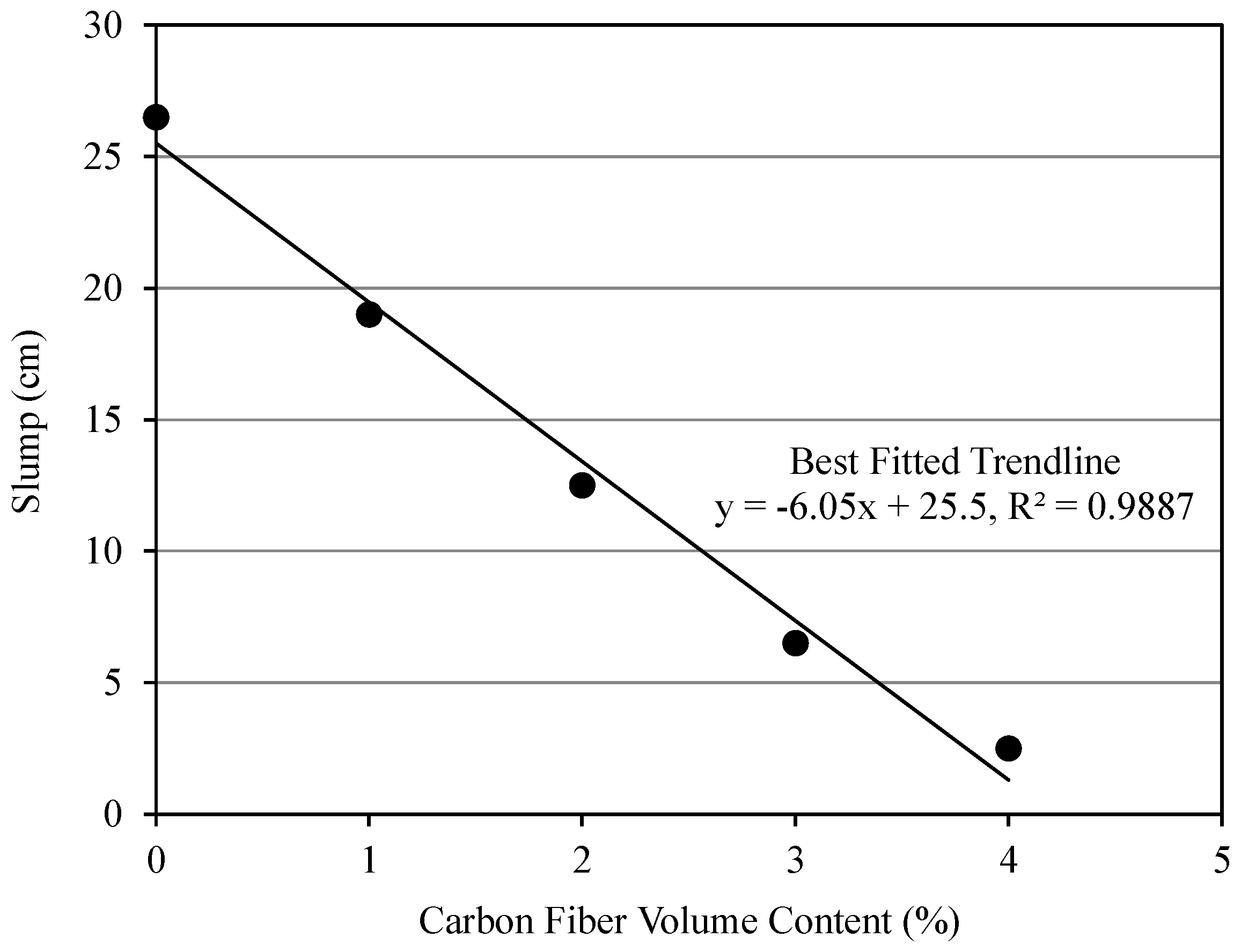
The slump test was conducted for each batch of the different types of freshly mixed mortar composite (two batches for every mortar mix). The detailed test results are shown in Table 7. The batch-to-batch variation of the slump (with respect to the average value) was in the range of 0 to ±4.0% for the high-workability mortar composites (NPCM, CFRM1, and CFRM2). This variation was in the range of ±7.69 to ±20.0% for the low-workability mortar composites (CFRM3 and CFRM4). However, the standard deviation of the slump ranged from 0 cm to 0.5 cm.
The effect of carbon fiber volume content on the slump of CFRM is shown in Figure 1. From Figure 1, it can be seen that the slump decreases linearly with the increase in carbon fiber volume content. Also, it was observed that the slump of CFRM is inversely proportional to the fiber volume content. For CFRMs, the slump diminished linearly with the increased volume content of carbon fibers. A similar effect was observed by Bayasi and Soroushian [29].
The volume content of fibers is a vital fiber parameter, which significantly influences the workability of fiber-reinforced cement composites. In the present study, the increase in the volume content of carbon fibers substantially reduced the workability of the fresh mortar composite. The large surface area of carbon fibers tends to restrain the mobility of the fresh mortar composite causing interlocking of the fibers. However, the uniform dispersion of carbon fibers in the presence of silica fume and superplasticizer resulted in an adequate slump in the freshly mixed CFRMs. The dispersion of carbon fibers was excellent due to the use of silica fume and superplasticizer. It has been shown experimentally that silica fume results in a more effective dispersion of carbon fibers and induces greater workability, homogeneity, formability, and fluidity in the fresh carbon fiber reinforced cement composites [30]. In addition, superplasticizer modified the fresh composite in a positive manner by altering its rheology. When a superplasticizer is added to cement composites, the cement particles are dispersed homogenously in the aqueous phase of the fresh composite and hence cement-water agglomerates cannot form [31]. This mechanism was conducive to prevent the accumulation of carbon fibers in the cases of CFRMs. Consequently, it reduced the inter-particle friction in the fresh mortar composites, and thus improved their workability. Therefore, no fiber ball was formed during the mixing operation. Also, fiber clumping was not noticed during the sampling and handling of the fresh mortar composite for the slump test.
The slump results indicate that a significantly low workability was obtained in the mortar mix having 4% carbon fiber volume content as compared to those with 1% and 2% volume contents due to the greater amount of carbon fibers. As a result, a relatively high dosage of superplasticizer was used to make it workable. The mixes with 1% and 2% carbon fiber contents required 2% and 3% superplasticizer (by weight of binder), respectively. In contrast, the mixes with 3% and 4% carbon fiber contents consumed 4% and 5% superplasticizer, respectively. The increased amount of superplasticizer in a CFRM with higher fiber content was beneficial to maintain an adequate workability for the compaction of the mortar composite.
The slump test is the most widely used single-point test. Unfortunately, it is not a good test to measure the relative workability of all cement composites. Especially, the slump is often misleading when applied to fiber-reinforced cement composites. For the stiff mixes of fiber-reinforced cement composites, this test does not provide an accurate indication of workability. For instance, in the present study, the slump test on the CFRM with 3% fiber content resulted in a low slump, but actually the mortar composite was adequately workable as indicated by the inverted slump cone flow test. Therefore, the slump test is not recommended for very low-slump fiber-reinforced cement composites [32]. The workability judged on the basis of slump may appear too low for the placement of fiber-reinforced cement composites, as the fibers impart substantial stability to the slump sample [33]. For this reason, the slump test is not an ideal test to measure the workability of carbon fiber reinforced composites. However, it can be used in addition to the flow test, or alone, when the correlation between slump and flow time is known.
4.2. Unit Weight and Air Content
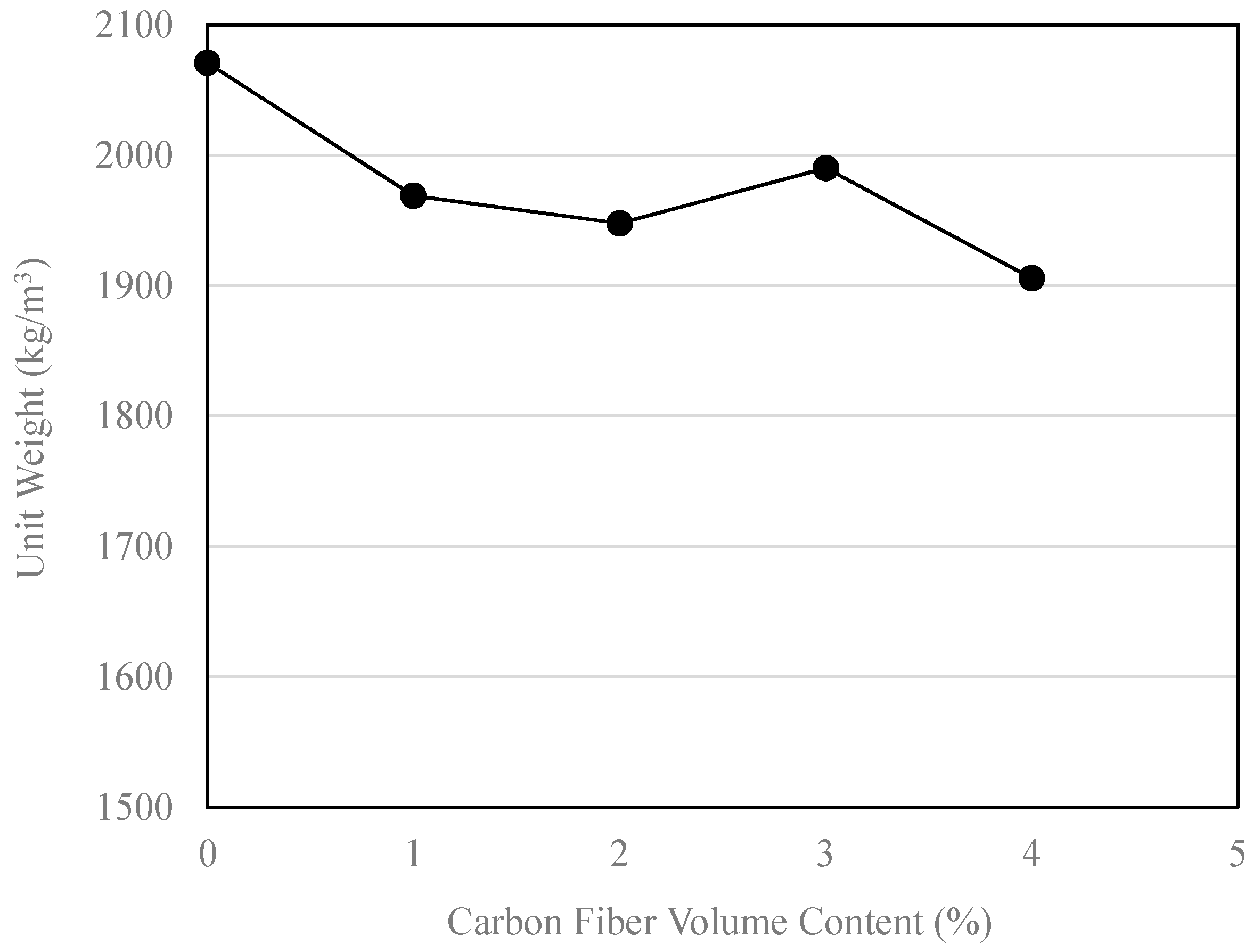
The test for unit weight and air content was carried out for each batch of different types of freshly mixed CFRM (two batches per mortar mix). The detailed test results are given in Table 7. The batch-to-batch variation of the unit weight (with regard to the average value) ranged from 0 to ±0.37% whereas this variation was in the range of +0.2/−0.1 to ±0.40% for the air content. The standard deviation of the unit weight and air content was 0–7.04 kg/m3 and 0.16–0.40%, respectively. Furthermore, the actual or measured air content did not differ too much from the air content assumed in the mix design calculations, as mentioned in Section 3.2.
The effects of different carbon fiber volume contents on the unit weight and air content are shown in Figure 2 and Figure 3, respectively. The unit weight of the mortar composite decreased with the inclusion of carbon fibers, as evident from Figure 2. This is mainly due to the drastic reduction in workability. Similar results were obtained by Akihama et al. [34] and Park et al. [30]. However, the decrease in unit weight was reduced at 3% volume content. This is mostly due to the improved workability and a greater degree of compaction. Moreover, the heterogeneity was reduced due to a more uniform distribution of carbon fibers throughout the mortar mix.
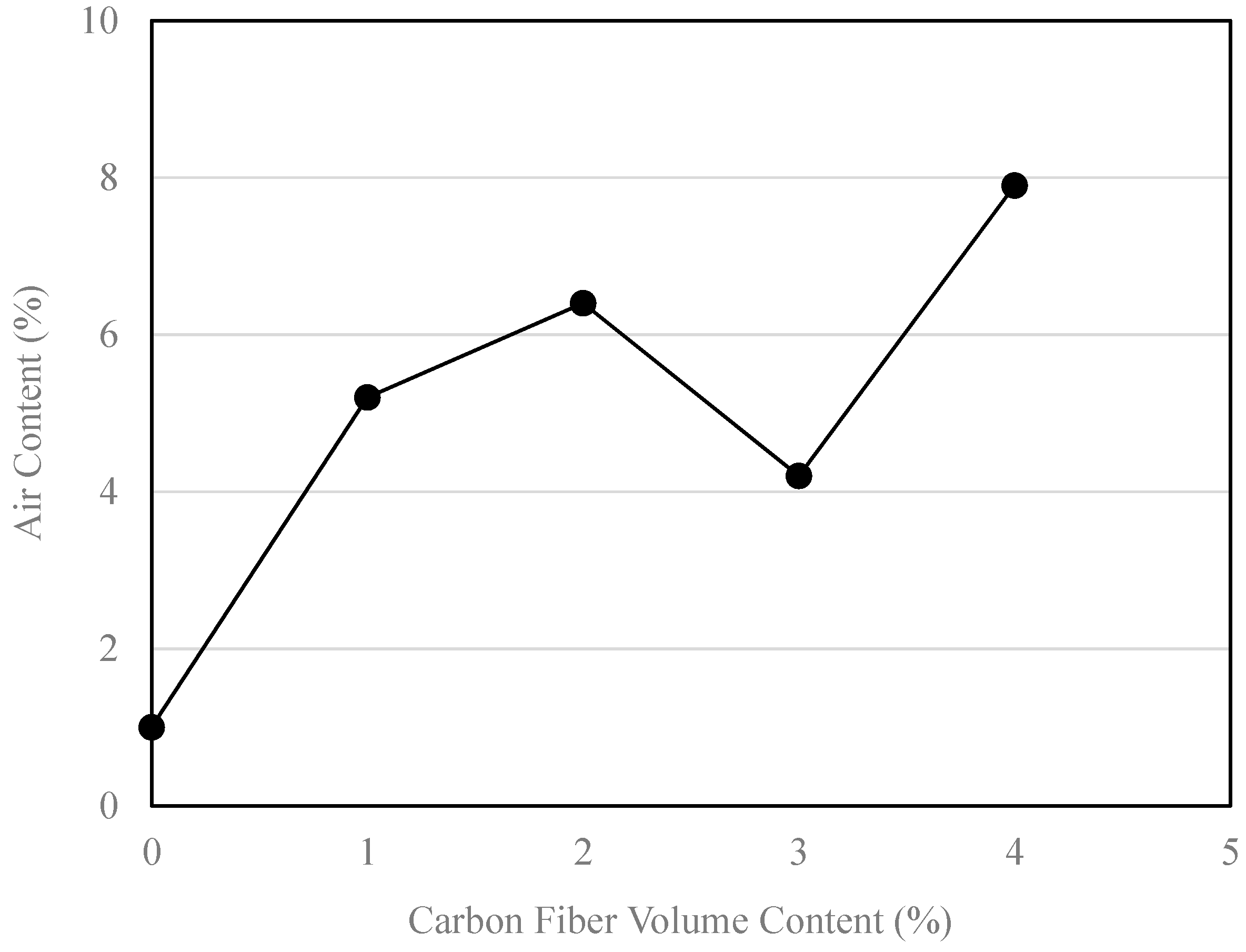
The air content of CFRM was much higher than that of NPCM. Also, the air content increased greatly with the increase in carbon fiber volume content, as can be seen from Figure 3. However, it is notable from Figure 3 that the CFRM with 3% fiber volume content had a comparatively low amount of air content. This is due to similar reasons as discussed in the case of unit weight.
The sand particles usually tend to prevent the air bubbles from rising to the surface during casting and compaction. The presence of short carbon fibers is likely to amplify this phenomenon [35]. However, the use of silica fume and superplasticizer dispersed the fibers and resulted in a reduced amount of air bubbles entrapped in the mix. In particular, the liquefying and dispersing effects of superplasticizer assist the entrapped air bubbles to exit the fresh mortar mix. The extents of liquefaction and dispersion obviously depend upon the dosage of superplasticizer. Perhaps, these effects combined with the effective compaction resulted in a relatively low air content in the CFRM with 3% fiber content. The largest air content was found in the CFRM containing 4% fiber content. This is mainly due to reduced workability and poor compaction. Since an excessive amount of superplasticizer is not conducive to cement hydration, more than 5% superplasticizer could not be used to make the mortar mix with 4% fiber content sufficiently workable. Consequently, this mortar mix was too stiff for good compaction. Hence, the degree of compaction was quite low, and therefore a greater amount of air bubbles was left in the mortar mix.
In general, the unit weight and air content are inter-related. The unit weight was reduced considerably owing to the air voids induced in the fresh mortar mix at the time of mixing. It is notable from Figure 2 and Figure 3 that the variations of unit weight and air content are somehow reciprocal—the greater the air content, the lower the unit weight. As the CFRM including 3% fiber content had a lower air content, it resulted in a higher unit weight.
4.3. Inverted Slump Cone Flow
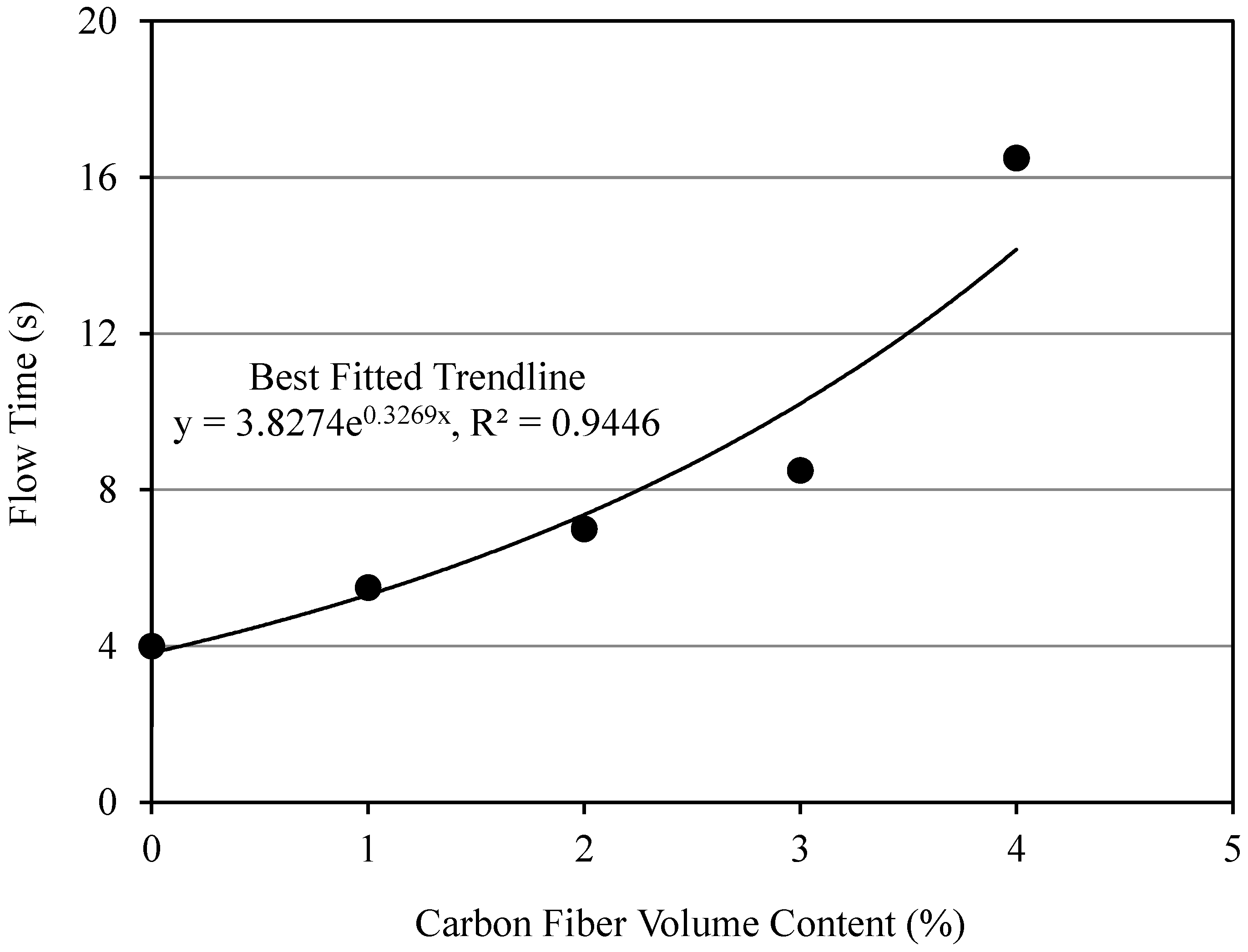
The inverted slump cone flow test was conducted for each batch of different types of freshly mixed mortar composite (two batches per mortar mix). The detailed test results are given in Table 8. The batch-to-batch variation of the flow time was in the range of 0 to ±9.09% and the standard deviation was 0–1.12 s.
The effect of different carbon fiber volume contents on the inverted slum cone flow time of CFRM are shown in Figure 4. It can be seen from Figure 4 that the flow time of the fresh mortar composite increases exponentially with the increase in carbon fiber volume content. It indicates that the workability of CFRM diminishes significantly with the increased carbon fiber content.
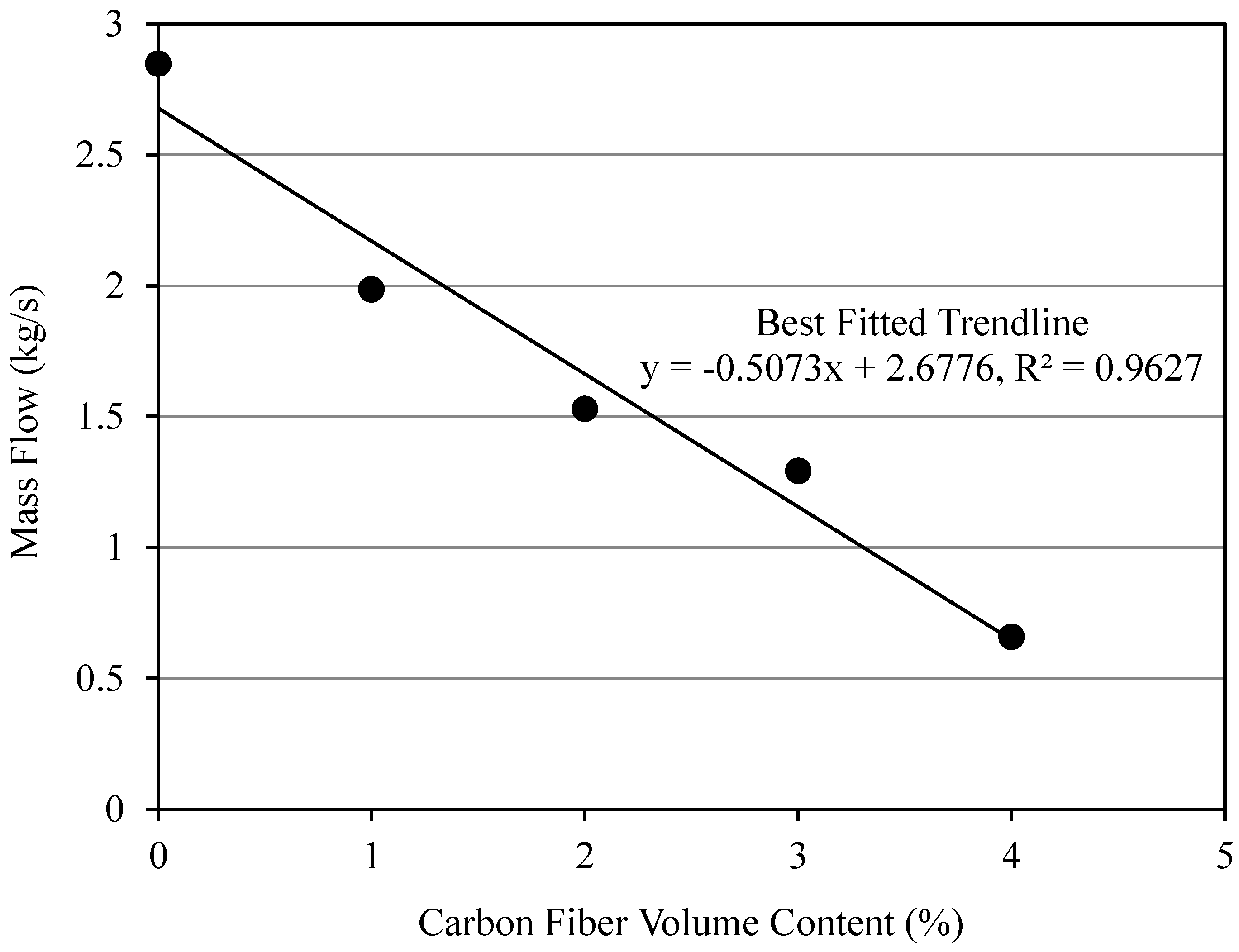
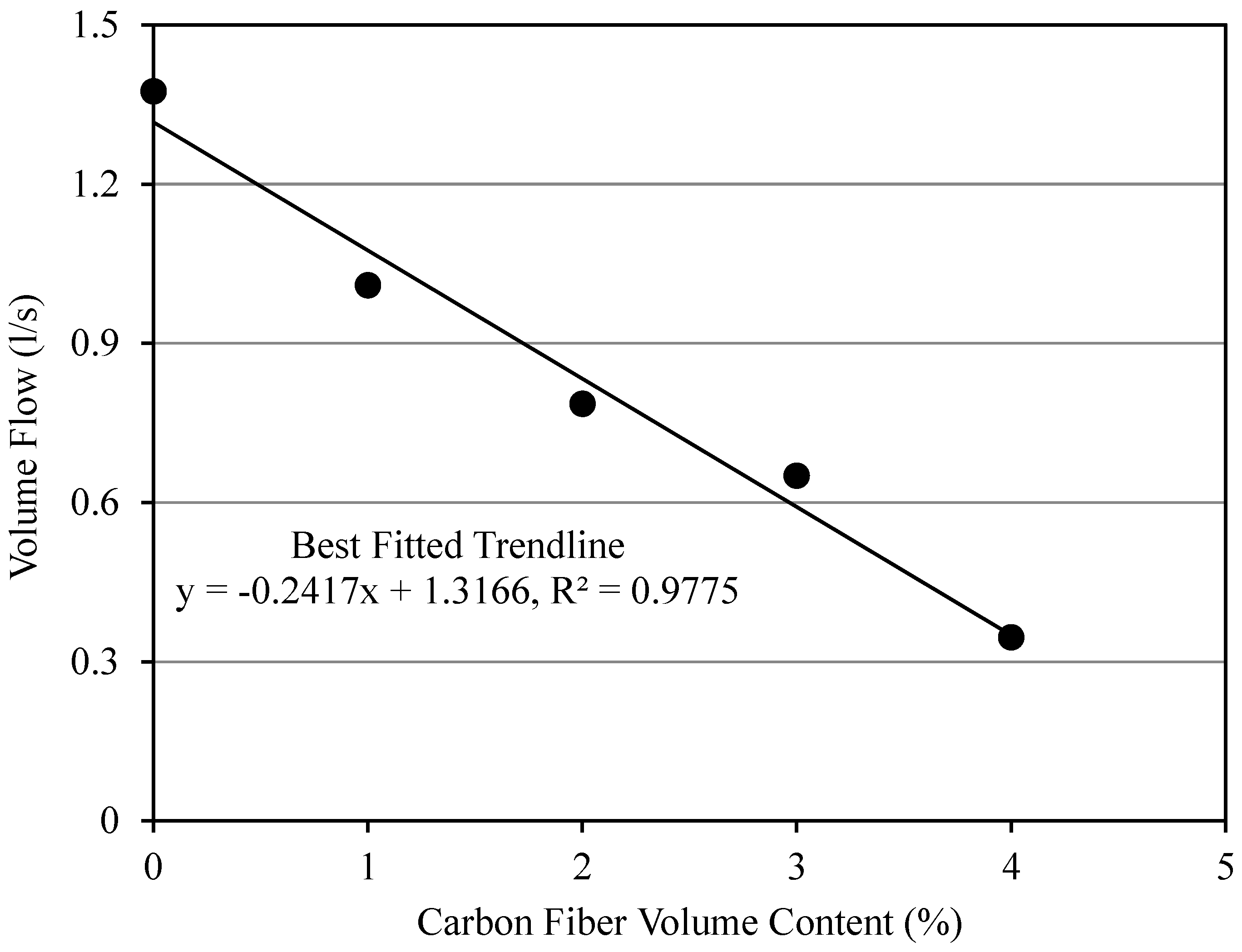
The mass flow of each mortar composite was computed using the unit weight, flow time, and corresponding volume of the fresh mortar, which is equal to the volume of the inverted slump cone. Also, the volume flow of each mortar composite was calculated from the flow time and corresponding volume of the fresh composite. The mass flow and volume flow values of NPCM and different CFRMs are given in Table 8. The batch-to-batch variation of the mass flow was in the range of −9.11 to +9.06%, whereas this variation ranged from −9.12 to 9.02% for the volume flow. The respective standard deviation of the mass flow and volume flow was 0.005–0.181 kg/s and 0–0.09 L/s.
The effect of carbon fiber volume content on the mass flow and volume flow of CFRM is shown in Figure 5 and Figure 6, respectively. It is evident from these figures that both the mass flow and volume flow of CFRM decreased almost linearly as the fiber volume content increased. Similar trends were observed in previous investigations conducted by Akihama et al. [34], Park et al. [30], and Banthia et al. [36].
The presence of carbon fibers significantly decreased the flow of CFRM. However, the liquefying action of superplasticizer and the dispersing roles of both silica fume and superplasticizer maintained good workability, homogeneity, formability, and fluidity in the mortar composite mixes. Usually, a flow time between 8 and 30 s indicates that the fresh composite is suitable for placement by vibration [33]. In the present study, the flow times were in the range of 4 to 17 s. Thus, the mobility or ability of the fresh composite to flow under vibration was excellent. It also indicates that the workability remained adequate over a wide range of fiber volume contents, even though the corresponding slump was quite low.
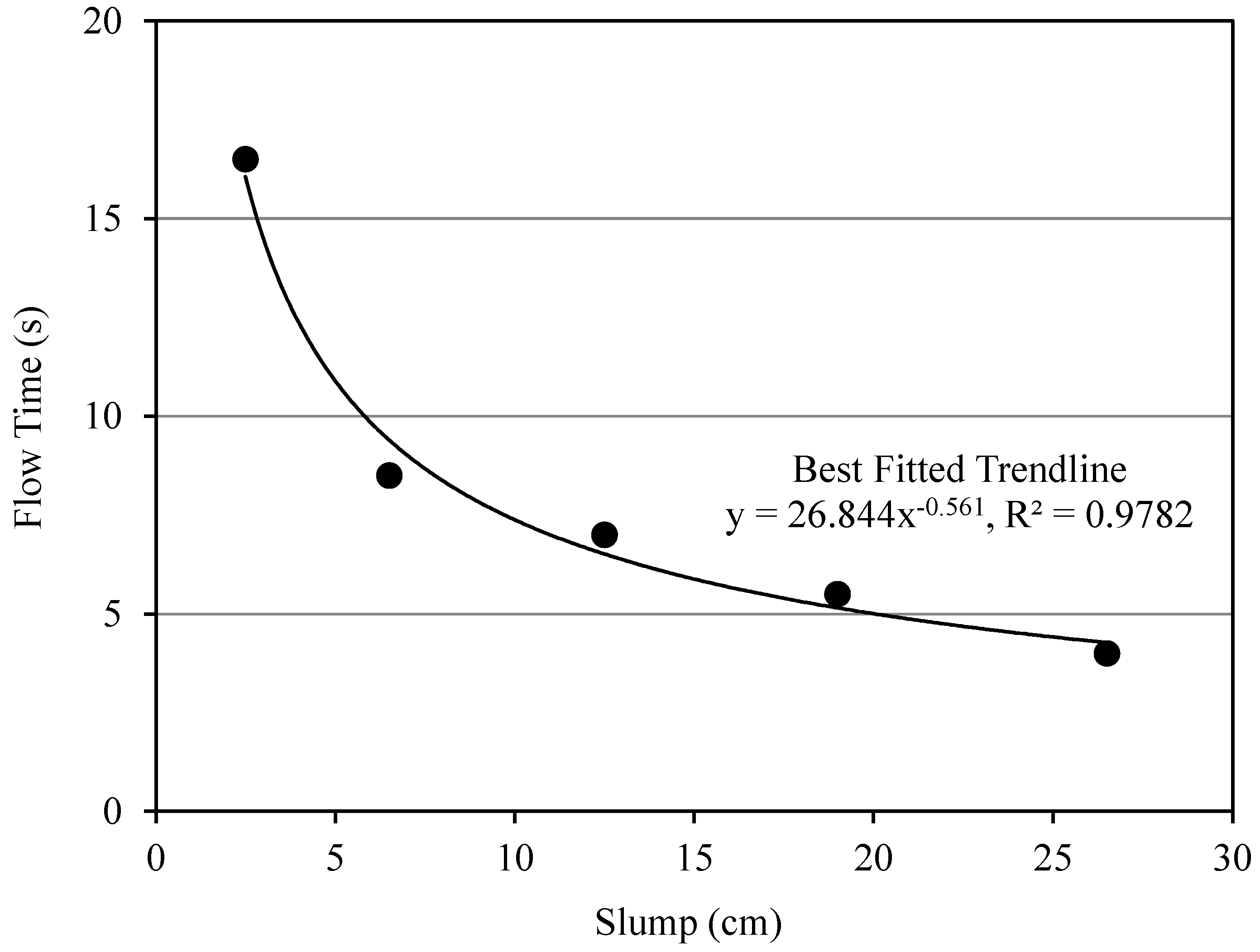
The slump and inverted slump cone flow time of CFRM can be correlated. A correlation between slump and flow time obtained from the present study is shown in Figure 7. It can be seen from this figure that CFRM flows well under vibration when the slump is greater than 10 cm. It also shows that the variation of the flow time is not significant above this slump. Hence, the results of the slump test can be accepted for a moderately to highly workable CFRM.
The inverted slump cone flow test is appropriate for fieldwork. It is portable and easier than the other flow tests such as the Vebe test. However, this test is generally not suitable for fiber-reinforced cement composites having a slump of more than 10 cm because the composite will flow through the cone very quickly [37]. This drawback has been eliminated in the present study by modifying the shape of the bucket and introducing a metal plate underneath the inverted slump cone so that it can retain the fresh composite during placement. It is also understood from the present study that the simple slump test can be conducted in the field if the correlation between the slump and inverted slump cone flow time is known for a given CFRM mix.
4.4. Optimum Mix
The optimal mix was defined based on the workability, unit weight, and air content of various mortar composites. In general, the air content of mortar increased whereas the slump, mass flow, volume flow, and unit weight decreased as the volume content of carbon fibers increased. Also, the inverted slump cone flow time was usually higher for the mortar with a larger amount of carbon fibers. From these perspectives, the mortar with 3% carbon fiber volume content was the optimal mix since it provided a good workability with adequate slump and flow to be placed and compacted by vibration, produced a reasonably good unit weight, and had a relatively low entrapped air content.
5. Conclusions
The following conclusions are drawn based on the properties of the freshly mixed control mortar and CFRM composites:
- The slump of the CFRM composites decreased linearly with the increased volume content of carbon fibers, which decreased the workability of mortar due to interlocking of the fibers.
- The CFRM composite mixes with low to medium fiber contents provide a sufficient slump (i.e., an adequate workability) for easy placement and good compaction of the fresh composites, in the presence of a liquefying and dispersing agent such as superplasticizer.
- The unit weights of the CFRM composites were lower than that of the control mortar because of the increased air content and lighter weight of carbon fibers.
- The air content in the CFRM composites was greater than that of the control mortar due to more entrapped air voids.
- The air content of the CFRM composites depended on their fiber volume content, workability, and degree of compaction, because they affect the release of air voids from fresh mortar composite.
- The inverted slump cone flow time of the CFRM composites increased predominantly with the increase in their fiber volume content that reduced the workability of mortar composite.
- The mass flow and volume flow of the CFRM composites decreased linearly with the increased fiber content, which increased the flow time of fresh mortar composite.
- The slump test was not always a satisfactory test for the CFRM composites since it did not deform similarly, as compared to the normal mortar.
- The slump test can be used for the CFRM composites when the correlation between the slump and inverted slump cone flow time is known.
- The CFRM composite mix with 3% fiber content was proven to be the optimum mix based on its performance with respect to slump, inverted slump cone flow (flow time, mass flow, and volume flow), unit weight, and air content.
Author Contributions
Conceptualization and Methodology, M.S. and G.A.-S.; Investigation, Data Curation, and Formal Analysis, M.S.; Supervision and Project Administration, G.A.-S. and N.H.; Writing—Original Draft Preparation, M.S.; Writing—Review and Editing, G.A.-S. and N.H.
Funding
This research received funding from the Ministry of Training, Colleges and Universities—Ontario, Canada.
Acknowledgments
The authors acknowledge the financial support provided by the Ministry of Training, Colleges and Universities of the Government of Ontario. The authors are also thankful to Master Builders Technologies, Ontario, Canada for supplying silica fume and superplasticizer required for the experimental investigation.
Conflicts of Interest
The authors declare no conflict of interest.
References
- Banthia, N.; Sheng, J. Strength and Toughness of Cement Mortars Reinforced with Micro-fibers of Carbon, Steel, and Polypropylene. In Proceedings of the Second Canadian Symposium on Cement and Concrete, Vancouver, BC, Canada, 24–26 July 1991; pp. 75–83. [Google Scholar]
- Soroushian, P.; Khan, A.; Hsu, J.W. Mechanical Properties of Concrete Materials Reinforced with Polypropylene or Polyethylene Fibers. ACI Mater. J. 1992, 89, 535–540. [Google Scholar]
- Pierre, P.; Pleau, R.; Pigeon, M. Mechanical Properties of Steel Microfiber Reinforced Pastes and Mortars. J. Mater. Civ. Eng. 1999, 11, 317–324. [Google Scholar] [CrossRef]
- Li, B.; Xu, L.; Shi, Y.; Chi, Y.; Liu, Q.; Li, C. Effects of Fiber Type, Volume Fraction and Aspect Ratio on the Flexural Acoustic Emission Behaviors of Steel Fiber Reinforced Concrete. Constr. Build. Mater. 2018, 181, 474–486. [Google Scholar] [CrossRef]
- Zhang, H.; Liu, Y.; Sun, H.; Wu, S. Transient Dynamic Behavior of Polypropylene Fiber Reinforced Mortar under Dynamic Loading. Constr. Build. Mater. 2016, 111, 30–42. [Google Scholar] [CrossRef]
- Marikunte, S.; Shah, S.P. High Performance Cement-based Composites for the Future. In Fiber Reinforced Concrete: Modern Developments; The University of British Columbia: Vancouver, BC, Canada, 1995; pp. 13–27. [Google Scholar]
- Sadati, S.; Khayat, K.H. Rheological and Hardened Properties of Mortar Incorporating High-Volume Ground Glass Fiber. Constr. Build. Mater. 2017, 152, 978–989. [Google Scholar] [CrossRef]
- Mohamed, M.A.S.; Ghorbel, E.; Wardeh, G. Valorization of Micro-Cellulose Fibers in Sel-Compacting Concrete. Constr. Build. Mater. 2010, 24, 2473–2480. [Google Scholar] [CrossRef]
- Gilson, J.C. Health Hazards of Asbestos. Composites 1972, 3, 57–59. [Google Scholar] [CrossRef]
- Bentur, A. Mechanisms of Potential Embrittlement and Strength Loss of Glass Fiber Reinforced Cement Composites. In Proceedings of the Symposium on Durability of Glass Fiber Reinforced Cement Concrete, PCI, Chicago, IL, USA, 12–15 November 1985; pp. 109–123. [Google Scholar]
- Soroushian, P.; Marikunte, S. Cellulose Fiber Reinforced Cement Composites: State-of-the-Art. In Proceedings of the First Canadian University/Industry Workshop on Fibre Reinforced Concrete, Quebec City, QC, Canada, 28–29 October 1991; pp. 44–58. [Google Scholar]
- ACI Committee 544. State-of-the-Art Report on Fiber Reinforced Concrete. In ACI Manual of Concrete Practice, Part 5; ACI 544.1R-96 (Reapproved 2002); American Concrete Institute: Detroit, MI, USA, 2002. [Google Scholar]
- Ali, M.A.; Majumder, A.J.; Rayment, D.L. Carbon Fiber Reinforcement of Cement. Cem. Concr. Res. 1972, 2, 201–212. [Google Scholar] [CrossRef]
- Akihama, S.; Suenaga, T.; Nakagawa, H. Carbon Fiber Reinforced Concrete. Concr. Int. 1988, 10, 40–47. [Google Scholar] [CrossRef]
- Banthia, N. Pitch-based Carbon Fiber Reinforced Cements: Structure, Performance, Applications and Research Needs. Can. J. Civ. Eng. 1992, 19, 26–38. [Google Scholar] [CrossRef]
- Banthia, N.; Genois, I. Pitch-based Carbon Fiber Reinforced Cement Composites. In Fiber Reinforced Concrete: Modern Developments; The University of British Columbia: Vancouver, CB, Canada, 1995; pp. 213–228. [Google Scholar]
- Ohama, Y.; Amano, M.; Endo, M. Properties of Carbon Fiber Reinforced Cement with Silica Fume. Concr. Int. 1985, 7, 58–62. [Google Scholar]
- Zheng, Q.; Chung, D.D.L. Carbon Fiber Reinforced Cement Composites Improved by Using Chemical Agents. Cem. Concr. Res. 1989, 19, 25–41. [Google Scholar] [CrossRef]
- Safiuddin, M.D.; Abdel-Sayed, G.; Hearn, N. High Performance Mortars with Short Carbon Fibers: Properties and Mix Optimization; Lambert Academic Publishing AG & Co. KG: Saarbrücken, Germany, 2010; 208p. [Google Scholar]
- ASTM C33/C33M-16. Standard Specification for Concrete Aggregates. In Annual Book of ASTM Standards, Vol. 04. 02; ASTM International: West Conshohocken, PA, USA, 2016. [Google Scholar]
- ASTM C150/C150M-16. Standard Specification for Portland Cement. In Annual Book of ASTM Standards, Vol. 04. 01; ASTM International: West Conshohocken, PA, USA, 2016. [Google Scholar]
- ASTM C1240-15. Standard Specification for Silica Fume Used in Cementitious Mixtures. In Annual Book of ASTM Standards, Vol. 04. 02; ASTM International: West Conshohocken, PA, USA, 2015. [Google Scholar]
- ASTM C94/C94M-16. Standard Specification for Ready-Mixed Concrete. In Annual Book of ASTM Standards, Vol. 04. 02; ASTM International: West Conshohocken, PA, USA, 2016. [Google Scholar]
- ASTM C494/C494M-16. Standard Specification for Chemical Admixtures for Concrete. In Annual Book of ASTM Standards, Vol. 04. 02; ASTM International: West Conshohocken, PA, USA, 2016. [Google Scholar]
- ASTM C172/C172M-14. Standard Practice for Sampling Freshly Mixed Concrete. In Annual Book of ASTM Standards, Vol. 04. 02; ASTM International: West Conshohocken, PA, USA, 2014. [Google Scholar]
- ASTM C143/C143M-16. Standard Test Method for Slump of Hydraulic-Cement Concrete. In Annual Book of ASTM Standards, Vol. 04. 02; ASTM International: West Conshohocken, PA, USA, 2016. [Google Scholar]
- ASTM C138/C138M-16. Standard Test Method for Density (Unit Weight), Yield, and Air Content (Gravimetric) of Concrete. In Annual Book of ASTM Standards, Vol. 04. 02; ASTM International: West Conshohocken, PA, USA, 2016. [Google Scholar]
- ASTM C995-01. Standard Test Method for Time of Flow of Fiber-Reinforced Concrete through Inverted Slump Cone. In Annual Book of ASTM Standards, Vol. 04. 02; ASTM International: West Conshohocken, PA, USA, 2002. [Google Scholar]
- Bayasi, M.Z.; Soroushian, J. Effect of Steel Fiber Reinforcement on Fresh Mix Properties of Concrete. ACI Mater. J. 1992, 89, 369–374. [Google Scholar]
- Park, S.B.; Lee, B.I.; Lim, Y.S. Experimental Study on the Engineering Properties of Carbon Fiber Reinforced Cement Composites. Cem. Concr. Res. 1991, 21, 589–600. [Google Scholar] [CrossRef]
- Erdogdu, S. Compatibility of Superplasticizers with Cements Different in Composition. Cem. Concr. Res. 2000, 30, 767–773. [Google Scholar] [CrossRef]
- Domone, P. The Slump Flow Test for High-Workability Concrete. Cem. Concr. Res. 1998, 28, 177–182. [Google Scholar] [CrossRef]
- Johnston, C.D. Fiber Reinforced Concrete. In Proceedings of the CANMET/ACI International Conference on Advances in Concrete Technology, Athens, Greece, 11–15 May 1992; pp. 629–697. [Google Scholar]
- Akihama, S.; Suenaga, T.; Banno, T. Mechanical Properties of Carbon Fiber Reinforced Cement Composites. Int. J. Cem. Compos. Lightweight Concr. 1986, 8, 21–33. [Google Scholar] [CrossRef]
- Pigeon, M.; Pleau, R.; Azzabi, M.; Banthia, N. Durability of Microfiber Reinforced Mortars. Cem. Concr. Res. 1996, 26, 601–609. [Google Scholar] [CrossRef]
- Banthia, N.; Dubeau, S. Carbon and Steel Micro-Fiber Reinforced Cement-based Composites for Thin Repairs. J. Mater. Civ. Eng. 1994, 6, 88–99. [Google Scholar] [CrossRef]
- Balaguru, P.N.; Shah, S.P. Fiber-Reinforced Cement Composites; International Edition; McGraw-Hill, Inc.: New York, NY, USA, 1992. [Google Scholar]
Figure 1.
Variation of slump with different carbon fiber volume contents.

Figure 2.
Variation of unit weight with different carbon fiber volume contents.

Figure 3.
Variation of air content with different carbon fiber volume contents.

Figure 4.
Variation of flow time with different carbon fiber volume contents.

Figure 5.
Variation of mass flow with different carbon fiber volume contents.

Figure 6.
Variation of volume flow with different carbon fiber volume contents.

Figure 7.
Correlation between the slump and inverted slump cone flow time of CFRM.


Table 1.
Physical properties of river sand (S).
| Property | Value or Percentage |
|---|---|
| Total Evaporable Moisture Content | 0.5% (by mass) |
| Saturated Surface Dry Basis Bulk Specific Gravity | 2.60 |
| Absorption | 1.6% (by mass) |
| Surface Moisture | 0% (by mass) |
| Maximum Particle Size | 2.36 mm |
| Fineness Modulus | 1.97 |
Table 2.
Sieve analysis of river sand.
| Sieve Size | Weight of Material Retained (g) | Percentage of Material Retained | Cumulative Percentage Retained | Total Percentage of Material Passing |
|---|---|---|---|---|
| 9.5 mm | 0 | 0 | 0 | 100 |
| 4.75 mm | 0 | 0 | 0 | 100 |
| 2.36 mm | 1.4 | 0.3 | 0.3 | 99.7 |
| 1.18 mm | 16.5 | 3.3 | 3.6 | 96.4 |
| 600 μm | 109.4 | 21.9 | 25.5 | 74.5 |
| 300 μm | 231.1 | 46.2 | 71.7 | 28.3 |
| 150 μm | 122.2 | 24.5 | 96.2 | 3.8 |
| Pan | 19.4 | - | - | - |
Table 3.
Chemical composition of normal Portland cement (NPC).
| Chemical Component | Mass Content (%) |
|---|---|
| CaO | 63.5 |
| SiO2 | 22.0 |
| Al2O3 | 5.5 |
| Fe2O3 | 2.5 |
| MgO | 2.0 |
| SO3 | 1.5 |
| K2O | 0.75 |
| Na2O | 0.25 |
| Loss on Ignition (LOI) | 2.0 |
Table 4.
Chemical composition of densified silica fume (SF).
| Chemical Component | Mass Content (%) |
|---|---|
| SiO2 | 90.8 |
| Al2O3 | 1.5 |
| Fe2O3 | 1.2 |
| CaO | 0.5 |
| MgO | 0.9 |
| Na2O | 0.5 |
| K2O | 1.9 |
| Loss on Ignition (LOI) | 2.7 |
Table 5.
Major physical and mechanical properties of pitch-based carbon fibers (CFs).
| Property | Value |
|---|---|
| Specific Gravity | 1.85 |
| Tensile Strength | 1770 MPa |
| Tensile Modulus | 180 GPa |
| Solubility in Water | None |
| Odor | Odorless |
Table 6.
Mix proportions of the various mortar composites.
| Mortar Mix | C (kg/m3) | S (kg/m3) | Sa (kg/m3) | SF (kg/m3) | CF (% V) | W (kg/m3) | Wa (kg/m3) | SP (% B) |
|---|---|---|---|---|---|---|---|---|
| NPCM | 955.9 | 562.3 | 556.2 | 168.7 | 0 | 393.6 | 394.1 | 1 |
| CFRM1 | 917.2 | 539.6 | 533.7 | 161.9 | 1 | 377.7 | 372.8 | 2 |
| CFRM2 | 898.0 | 528.2 | 522.4 | 158.5 | 2 | 369.8 | 359.8 | 3 |
| CFRM3 | 878.6 | 516.9 | 511.3 | 155.1 | 3 | 361.8 | 346.7 | 4 |
| CFRM4 | 859.4 | 505.5 | 500.0 | 151.7 | 4 | 353.9 | 334.1 | 5 |
B: binder (cement plus silica fume) content, C: cement content, CF: carbon fibers, CFRM: carbon fiber reinforced mortar, NPCM: normal Portland cement mortar, S: sand content, Sa: adjusted sand content, SF: silica fume, V: mortar volume, W: water content Wa: adjusted water content.
Table 7.
Slump, unit weight, and air content of various fresh mortar composites.
| Mortar Mix | Slump (cm) | Unit Weight (kg/m3) | Air Content (%) |
|---|---|---|---|
| NPCM * | 26.5 | 2070.7 | 1.0 |
| CFRM1 | 19 | 1968.8 | 5.2 |
| CFRM2 | 12.5 | 1947.7 | 6.4 |
| CFRM3 | 6.5 | 1989.9 | 4.2 |
| CFRM4 | 2.5 | 1905.5 | 7.9 |
* Self-compactable.
Table 8.
Inverted slump cone flow of various fresh mortar composites.
| Mortar Mix | Flow Time (s) | Mass Flow (kg/s) | Volume Flow (L/s) |
|---|---|---|---|
| NPCM * | 4 | 2.848 | 1.375 |
| CFRM1 | 5.5 | 1.986 | 1.009 |
| CFRM2 | 7 | 1.530 | 0.786 |
| CFRM3 | 8.5 | 1.293 | 0.650 |
| CFRM4 | 16.5 | 0.658 | 0.346 |
* Self-compactable.
© 2018 by the authors. Licensee MDPI, Basel, Switzerland. This article is an open access article distributed under the terms and conditions of the Creative Commons Attribution (CC BY) license (http://creativecommons.org/licenses/by/4.0/).
Share and Cite
MDPI and ACS Style
Safiuddin, M.; Abdel-Sayed, G.; Hearn, N. Effects of Pitch-Based Short Carbon Fibers on the Workability, Unit Weight, and Air Content of Mortar Composite. Fibers 2018, 6, 63. https://0-doi-org.brum.beds.ac.uk/10.3390/fib6030063
AMA Style
Safiuddin M, Abdel-Sayed G, Hearn N. Effects of Pitch-Based Short Carbon Fibers on the Workability, Unit Weight, and Air Content of Mortar Composite. Fibers. 2018; 6(3):63. https://0-doi-org.brum.beds.ac.uk/10.3390/fib6030063
Chicago/Turabian StyleSafiuddin, Md., George Abdel-Sayed, and Nataliya Hearn. 2018. "Effects of Pitch-Based Short Carbon Fibers on the Workability, Unit Weight, and Air Content of Mortar Composite" Fibers 6, no. 3: 63. https://0-doi-org.brum.beds.ac.uk/10.3390/fib6030063
Note that from the first issue of 2016, this journal uses article numbers instead of page numbers. See further details here.