Article

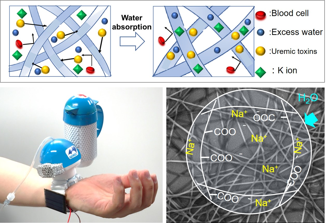
Fabrication of Water Absorbing Nanofiber Meshes toward an Efficient Removal of Excess Water from Kidney Failure Patients

1
Graduate School of Industrial Science and Technology, Tokyo University of Science, Katsushika-ku, Tokyo 125-8585, Japan
2
International Center for Materials Nanoarchitectonics (WPI-MANA), National Institute for Materials Science (NIMS), Tsukuba, Ibaraki 305-0044, Japan
3
Graduate School of Pure and Applied Sciences, University of Tsukuba, Tsukuba, Ibaraki 305-8577, Japan
*
Author to whom correspondence should be addressed.
Submission received: 22 February 2019 / Revised: 19 April 2019 / Accepted: 22 April 2019 / Published: 1 May 2019
(This article belongs to the Special Issue Electrospun Polymer Nanofibers for Food and Health Applications)

Abstract

:
Excellent water-absorbing nanofiber meshes were developed as a potential material for removing excess fluids from the blood of chronic renal failure patients toward a wearable blood purification system without requiring specialized equipment. The nanofiber meshes were successfully fabricated from poly(acrylic acid) (PAA) under various applied voltages by appropriately setting the electrospinning conditions. The electrospun PAA nanofibers were thermally crosslinked via heat treatment and then neutralized from their carboxylic acid form (PAA) to a sodium carboxylate form poly(sodium acrylate) (PSA). The PSA nanofiber meshes exhibited a specific surface area 393 times that of the PSA film. The PSA fiber meshes showed a much faster and higher swelling than its corresponding film, owing to the higher capillary forces from the fibers in addition to the water absorption of the PSA gel itself. The proposed PSA fibers have the potential to be utilized in a new approach to remove excess water from the bloodstream without requiring specialized equipment.

Graphical Abstract

1. Introduction

The main function of the kidneys is to filter blood to remove waste products such as uremic toxins and excess water in the form of urine. Kidney failure or renal failure is the last stage of chronic kidney disease in which the kidneys no longer function, causing impaired consciousness, heart failure, pulmonary edema, and subcutaneous bleeding [1]. The most common treatment for kidney failure is hemodialysis (HD). As of 2015, it is reported that approximately 2.6 million patients undergo regular dialysis treatments worldwide, and the number of patients is expected to increase to 5.6 million by 2030 [1,2,3].
One of the disadvantages of HD treatment is that it requires substantial resources, including 150+ liters of water, because the mechanism of HD is based on a diffusion-limited process wherein the blood flows along an external semipermeable membrane and excess wastes or fluids pass into a dialysate solution [4,5]. Despite recent improvements in the efficiency and selectivity properties of dialysis membranes, the diffusion-based HD process is inconvenient, time-consuming, and expensive [6]. In particular, HD treatments have been severely restricted in developing countries and during natural disasters because of the lack of dialysis supplies and frequent electricity outages, resulting in over 1 million people worldwide die from untreated kidney failure annually [7,8,9,10]. Notably, during the 2011 Tohoku earthquake and tsunami in Japan, many dialysis systems were damaged, and large shortages of dialysate, water, and electricity created an extremely dangerous situation for HD-dependent patients [11,12]. Therefore, it is necessary to develop simpler and more-accessible methods for kidney failure treatments worldwide. From these perspectives, we focused on utilizing selective absorption as a technique for blood purification. In particular, we focused on a water-absorbing mechanism (materials) instead of a diffusion-based process to avoid the use of 150+ liters of water. In our previous work, we prepared a zeolite–polymer composite nanofiber mesh to selectively absorb the uremic toxin creatinine using a biocompatible polymer, namely poly(ethylene-co-vinyl alcohol) [13,14]. Nanofiber meshes have many advantages, such as large specific surface areas, excellent mechanical properties, low pressure losses, and ease of handling [15,16]. Several techniques are available for synthesizing nanofibers. Among them, electrospinning method has been demonstrated to provide promising results in various fields [17,18,19,20,21]. Electrospinning is a relatively inexpensive and simple method for producing a variety of nano- and micro-scale fibers with uniform diameters [22,23].
In addition to creatinine, uremic toxins (such as urea), as well as excess water and electrolytes should be removed through dialysis treatments. A high water content in the body is directly linked to weight gain, swelling, breathing difficulty, hypertension, heart failure, and pulmonary edema [7,8,9,10]. In this work, we focus on poly(sodium acrylate) (PSA) gels as a potential material for removing excess fluids from the blood of chronic renal failure patients. PSA is a strongly hydrophilic polymer owing to its pendent carboxylate anions, and it can absorb more than 10 times its own weight to form a gel. Therefore, it is commonly used in disposable diapers and sanitary supplies [24,25,26]. The water absorption ability can be improved by preparing nanofiber meshes out of PSA owing to the higher capillary forces from the fibers in addition to the water absorption of the PSA gel itself. In this study, we developed a PSA nanofiber mesh as a wearable blood purification system without requiring specialized equipment.

2. Materials and Methods

2.1. Materials

Poly(acrylic acid) (PAA) (average MV = 250,000 g mol−1), ethylene glycol (EG) (anhydrous), sodium citrate, sulfuric acid, ethanol, and methanol were purchased from Wako Pure Chemicals (Osaka, Japan). Poly(vinyl pyrrolidone) (PVP; MW = 360,000 g mol−1) and Dulbecco’s phosphate buffered saline were purchased from Sigma-Aldrich (Madison, WI, USA) and used without further purification. Female severe combined immunodeficiency (SCID) mice 6 weeks of age were obtained from Charles River Laboratories Japan, Inc. (Yokohama, Japan). All animal care and experimental procedures were approved by the Experimental Animal Administration Committee of National Institute for Materials Science (Approval No. 36-2013-2).

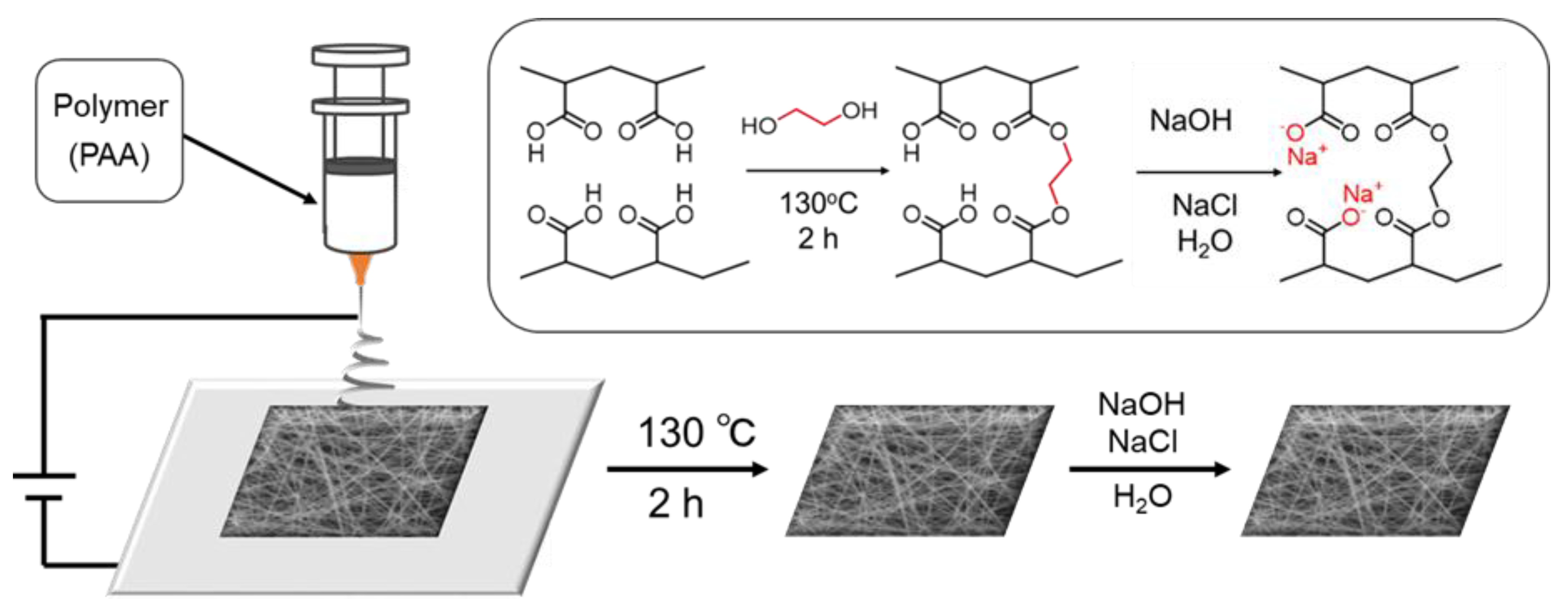
2.2. Fiber Fabrication

Electrospinning solutions were prepared by dissolving 8 or 10 wt/v% PAA in methanol or ethanol. EG was added to each sample as a crosslinking agent at concentrations of 10 and 16 wt% relative to the PAA, and complete dissolution was observed after 24 h of mixing using a magnetic stirrer at room temperature. Sulfuric acid (1 mol L−1) was added to the PAA–EG solution immediately before electrospinning at a concentration of 50 μL mL−1. Additionally, PVP ethanol solutions were prepared, with a concentration of 10 wt/v%. The electrospinning was performed using a NANON-03A electrospinning machine (MECC, Fukuoka, Japan). To facilitate the removal of electrospun PAA from the aluminum foil, a thin layer of PVP fibers were deposited by electrospinning the PVP solutions prior to PAA as a sacrificial layer. For the PVP fibers, the following parameters were kept constant: an applied voltage of 15 kV, a flow rate of 0.8 mL h−1, and a working distance of 15 cm. A 25-gauge pointed needle was used. For the PAA fibers, the spinning parameters were kept constant: a flow rate of 0.6 mL h−1 and a working distance of 10 cm; a 25-gauge pointed needle was used, and the applied voltages selected were 10, 15, 20, 25, and 30 kV. The fibers were electrospun onto a aluminum foil sheet placed on a stationary plate collector. The electrospun PAA nanofibers were thermally crosslinked on the mandrel via heat treatment in a vacuum oven (at 130 °C with a reduced pressure of 25 mmHg (84.7 kPa)) for 30 min and then cooled to room temperature. Prior to characterization, the electrospun fibers were removed from the foil in water to dissolve and wash off the sacrificial layer. The PAA nanofibers were neutralized from their carboxylic acid form (PAA) to a sodium carboxylate form (PSA) by immersing them in a 1 mol L−1 NaOH and 1 mol L−1 NaCl solution for approximately 1 h, then rinsing with water to remove any residual salts. To confirm the success of intermolecular crosslinking after the reaction, the disappearance of the carboxy groups in PAA was observed by ATR–FTIR spectroscopy (Thermoscientific Nicolet 4700, Thermo, Waltham, MA, USA). Figure 1 shows the fabrication process of the PSA nanofiber mesh using the electrospinning method.

2.3. Fiber Characterization

The fiber morphologies were observed using a Hitachi S-4800 field emission scanning electron microscope (FESEM) (Hitachi, Tokyo, Japan). Prior to imaging, the samples were sputter coated with ∼3 nm platinum using an E-1030 Ion Sputterer (15 mA, 30 s, 6.0 Pa) (Hitachi). Lower-resolution images were obtained using a NeoScope JCM-5000 benchtop SEM (JEOL, Tokyo, Japan). The fiber diameters were measured using the ImageJ software (Image J 1.52a USAJAVA 1.8.0_112 (64-bit), the National Institutes of Health, Bethesda, MD, USA) and presented as an average with standard deviations (n = 40). The N2 gas adsorption/desorption isotherms and Brunauer–Emmett–Teller (BET) surface area were characterized using a BELSORP-mini ASAP 2020 analyzer (BEL Japan, Inc., Osaka, Japan).

2.4. Swelling Behavior of Nanofiber Meshes and Films

The swelling ratio of the nanofiber mesh and film were determined from the relationship
swelling ratio = (WSW0)/W0,
where W0 is the dry weight of the PAA (or PSA), and WS is the weight of the swollen sample immersed in the solution at room temperature, after the excess water on the sample surfaces was imbibed with a Kimwipe (n = 3).

3. Results and Discussion

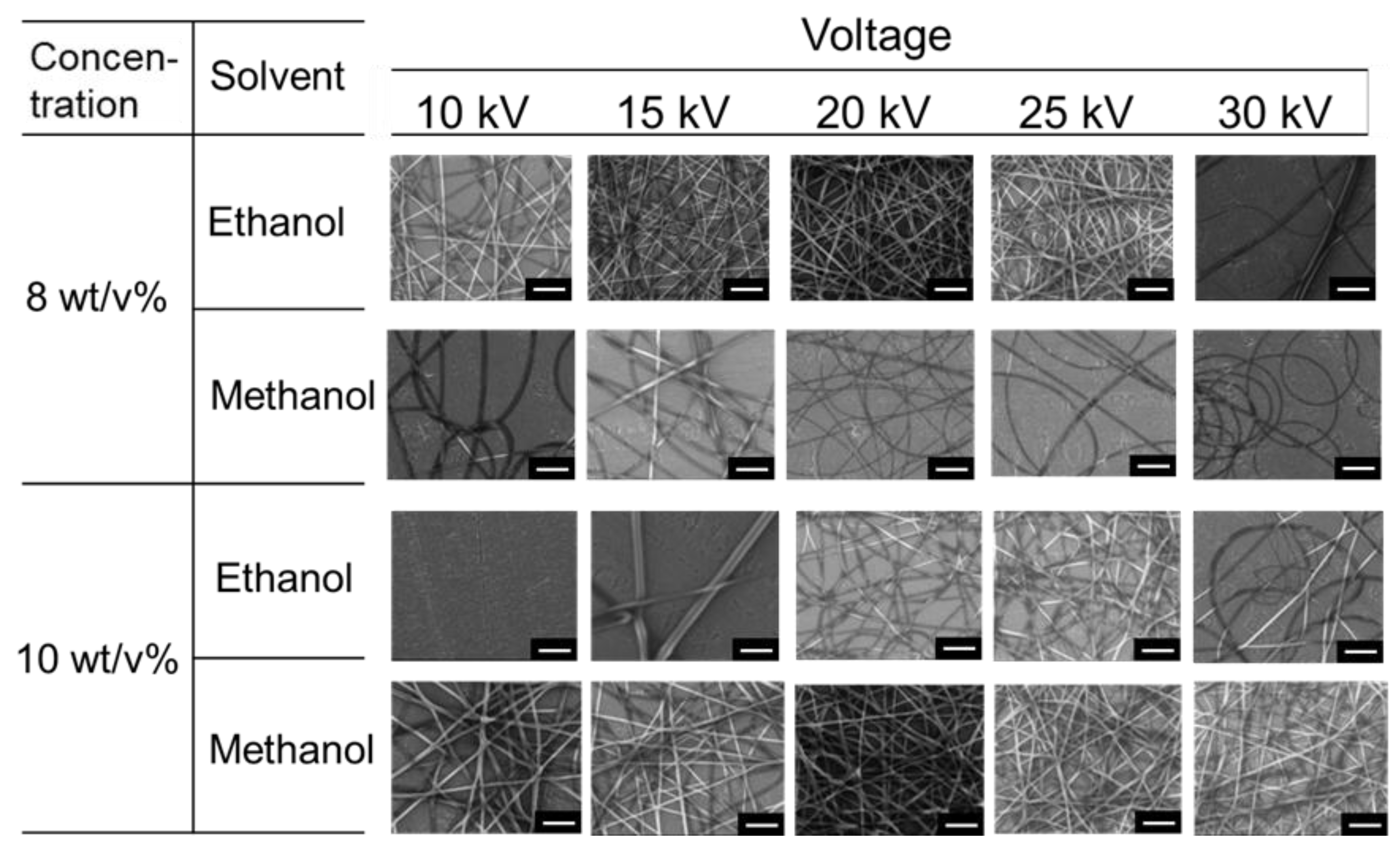
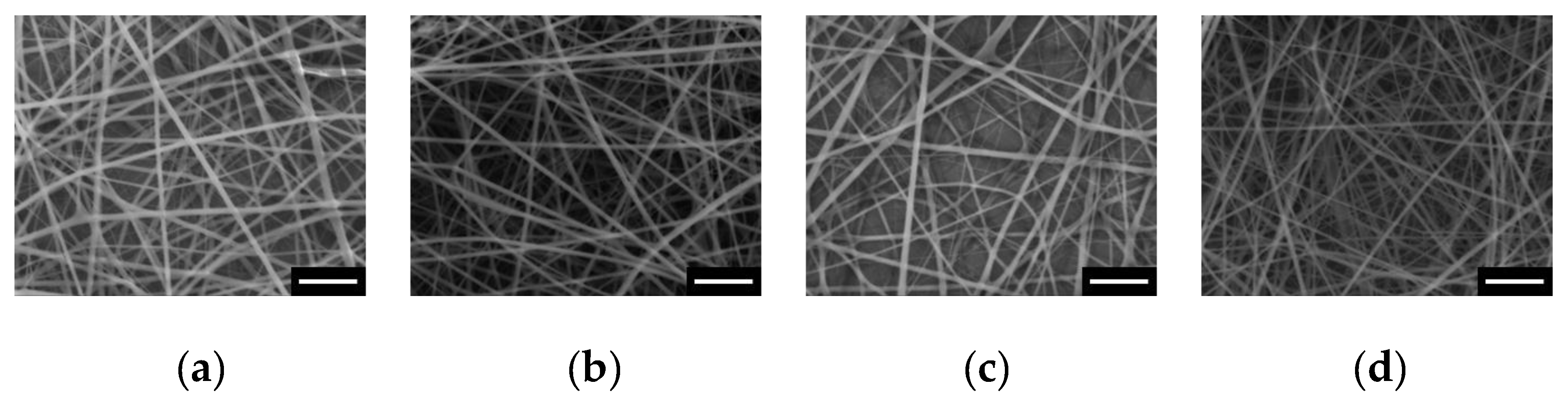
3.1. Fabrication of PSA Nanofiber Meshes

In this work, nanofiber meshes made of a water-absorbing polymer (i.e., PSA), with a hydrophilic sodium carboxylate group were prepared. First, PVP nanofibers were formed as a sacrificial layer by electrospinning, followed by electrospinning the PAA nanofibers from solutions of varying concentrations, solvents, and voltages. The PAA nanofiber mesh was neutralized to its PSA form and examined using the FESEM. As shown in Figure 2, stable PAA nanofiber meshes were observed regardless of solvents (ethanol and methanol). When preparing nanofiber meshes at different concentrations, we found that 10 wt/v% PAA produced homogeneous fibers with less dispersity compared with the 8 wt/v% solutions. We could not fabricate fine nanofibers at a concentration of below 6 or above 10 wt/v%. The effect of voltage on the PAA fiber diameter was also examined for those made with 10 wt/v% solutions in methanol (Figure 2). The combined action of the Coulombic forces, surface tension, and viscosity tends to affect the diameter of the electrospun nanofibers (Figure 3). The nanofibers electrospun at low potentials tend to have large diameters with the presence of beads because of the weaker Coulombic forces relative to the surface tension and viscoelasticity. With an increase in the applied voltage, the Coulombic forces increased, and fibers with a narrow diameter distribution were formed when the three forces balanced each other. The voltage varying in the range of 10–30 kV applied to the electrospun PAA is consistent with these principles, as the fiber diameters decreased with the increase in the voltage. Based on these experimental results, we found that PAA fibers prepared in 10 wt/v% of methanol at 30 kV were optimal, owing to their high surface area and narrow fibers.

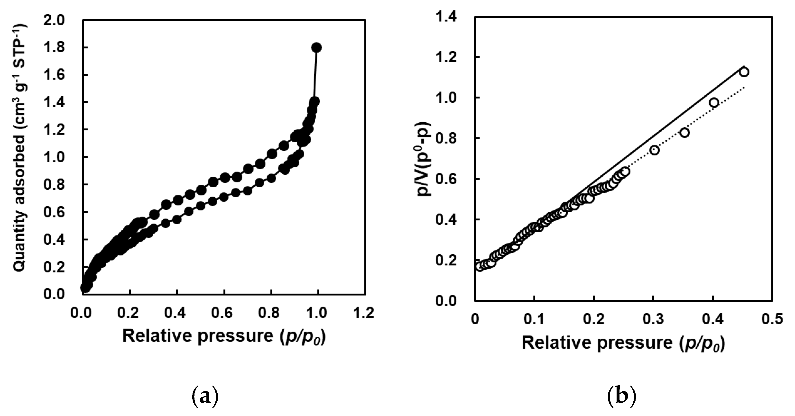
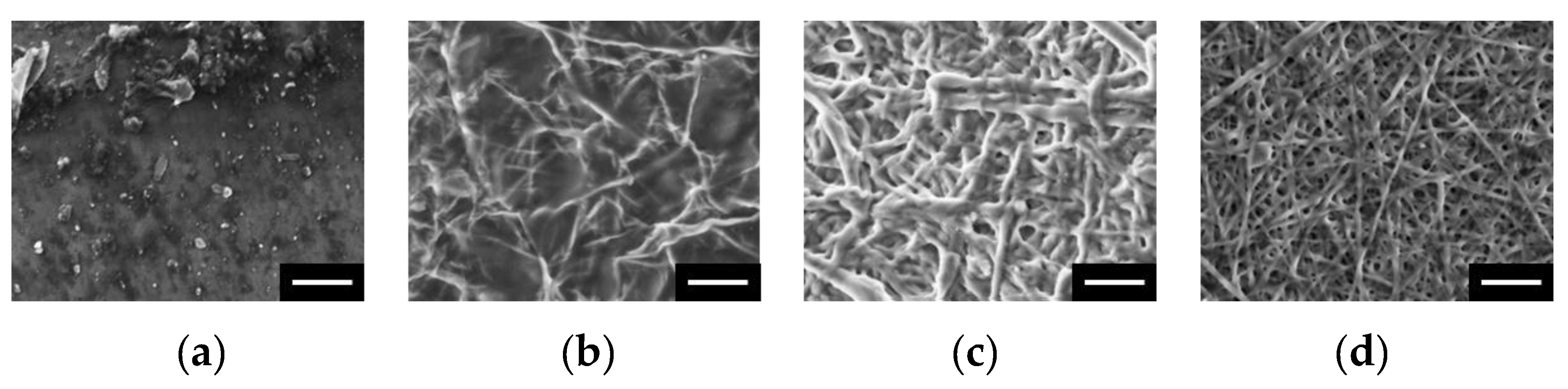
3.2. Porous Structure Analysis of PSA Nanofiber Meshes

To analyze the specific surface area of the nanofiber meshes and the structure between the fibers, a nitrogen adsorption test was carried out on vacuum-dried PSA nanofiber meshes. The adsorption/desorption isotherms (Figure 4) show typical IV-type properties with an H3 hysteresis loop. From this hysteresis loop, we can conclude that the nanofiber meshes have a mesoporous structure [27,28,29]. The calculated BET surface area was 1.6536 m2/g, while that of the corresponding film was 0.004 m2/g. Therefore, the nanofiber mesh was found to have a specific surface area 393 times that of the PSA films. Stable fibers were formed when electrospinning PAA meshes with EG as a crosslinking agent, regardless of the EG concentration (Figure 5). In addition, the concentration of the crosslinking agent had little effect on the fiber diameter. Figure 5 shows the SEM images of the PAA nanofiber meshes added with 0, 0.16, 1.6, and 16 wt% of the EG crosslinking agent.
Next, the stability of the fibers with different crosslinking densities was investigated by immersing them in water. In Figure 6a, no fibers are observed because the PSA dissolved into the solution. Increasing the EG concentration to 0.16% resulted in an ill-defined structure with no stable fibers (Figure 6b). A fibrous network was obtained at an EG concentration of 1.6 wt%; however, the individual fibers were highly swollen and adhered to each other. At 16 wt% EG crosslinking, a stable nanofiber mesh with well-defined PSA fibers was observed. The success of intermolecular crosslinking was also confirmed by ATR–FTIR spectroscopy (Supplementary Materials: Figure S6). These results demonstrate that the structure of the PSA nanofiber mesh can be changed by varying the amount of EG, with an improved fiber stability at higher crosslinking densities.

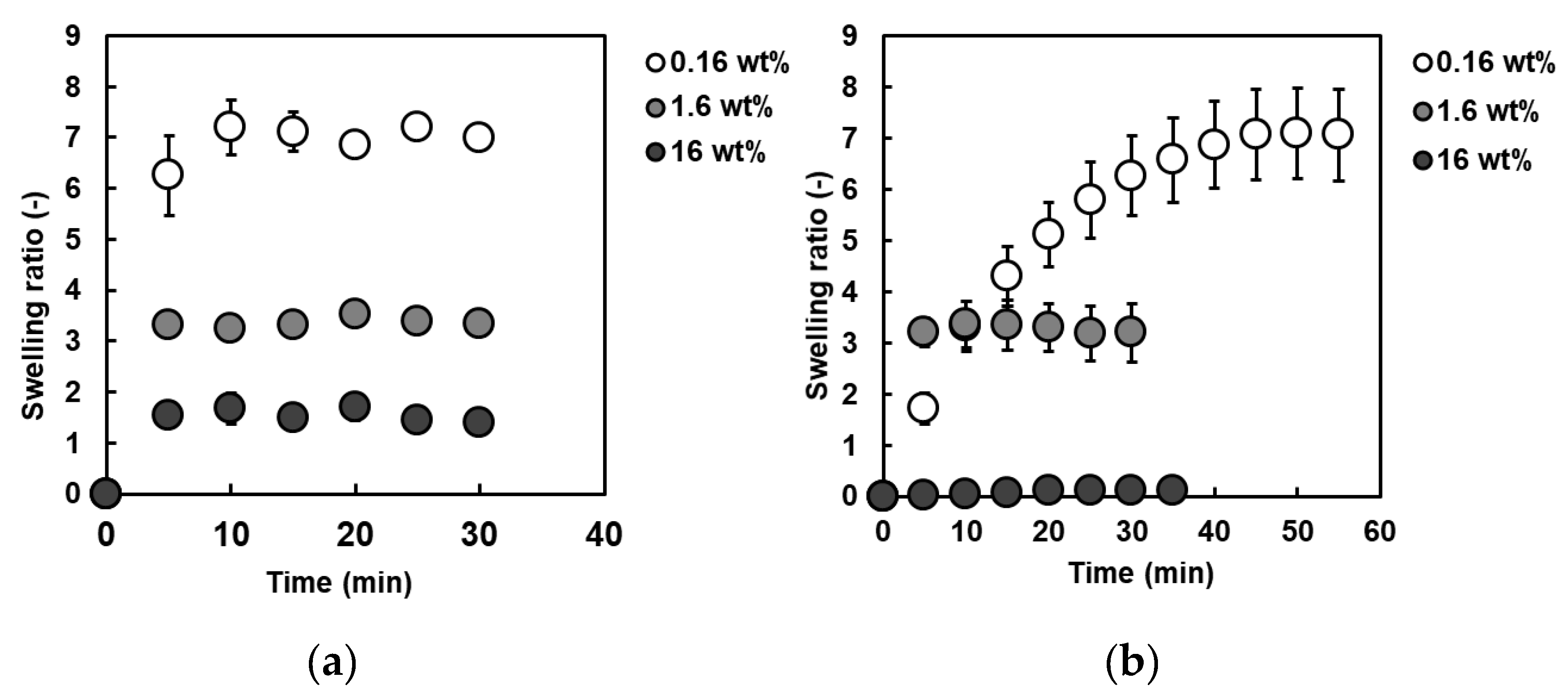
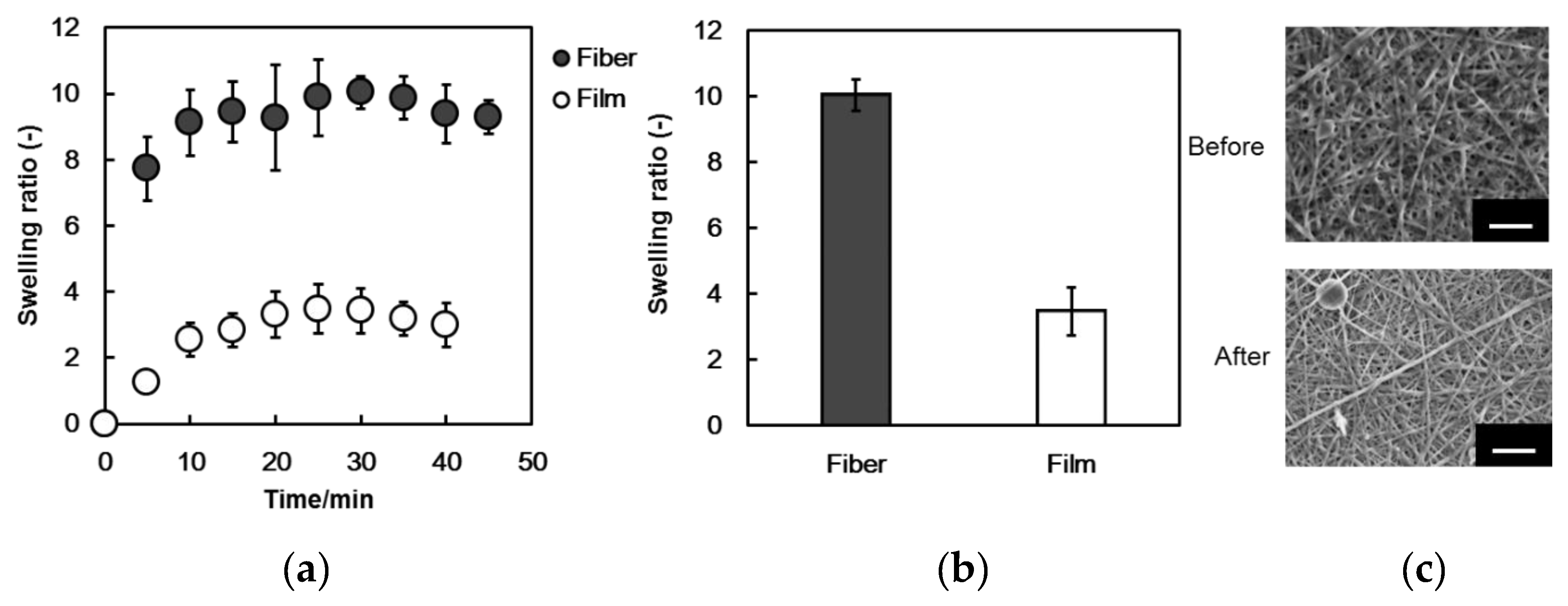
3.3. Water Absorption Test on PSA Nanofiber Meshes

To test the water absorption properties of our nanofibers, dried PSA meshes or films prepared with various concentrations of the EG crosslinking agent were immersed in phosphate buffered saline (PBS), and the masses of the fibers or films were measured every 5 min until equilibrium absorption was reached (Figure 7). As shown in Figure 7a,b, the swelling ratio of both the nanofiber meshes and films decreased with an increase in the concentration of the crosslinking agent. This trend suggests an increase in the crosslinking density of the PSA fibers and films at higher EG concentrations. Comparing the swelling ratios of the nanofiber meshes and films at each concentration, we find that the final swelling ratios were very similar under most conditions. However, a remarkable difference is observed in the swelling rate at an EG concentration of 0.16 wt%. Specifically, the swelling ratio of the nanofiber meshes quickly reached its maximum in 5 min, whereas the film took 40 min to reach equilibrium swelling. This difference is attributed to the high surface area of the PSA nanofiber mesh relative to the film. However, at an EG concentration of 1.6 wt%, there was no significant difference in the swelling ratio or swelling rate between the meshes and the films. In this case, the difference in the surface area did not lead to any noticeable changes in the swelling speeds, probably because the concentration of the crosslinking agent and the crosslinking density were too high. At an EG concentration of 16 wt%, little to no swelling was observed in the PSA film, whereas significant swelling occurred in the mesh. This difference in the swelling ratio can be attributed to the high capillary forces of the stable nanofibers at higher crosslinking densities. Swelling due to the capillary forces of the fibers was not observed at EG concentrations of 0.16 and 1.6 wt% because of their collapsed structure, as shown in Figure 6.
Subsequently, a water absorption test was carried out on the PSA nanofiber meshes and films prepared with an EG concentration of 16 wt% in mouse blood. The PSA nanofiber mesh exhibited a swelling ratio approximately 10 times its own weight, whereas the swelling of the PSA film was 2.5 times lower at an approximate swelling ratio of 4 (Figure 8). This result is consistent with the previous absorption test conducted in PBS, wherein the nanofiber mesh exhibited a higher swelling ratio because of its increased surface area and capillary forces. The SEM images of the PSA nanofibers taken after the water absorption test in the mouse blood show that the meshes retained their shape and that the fiber diameter remained the same. However, some components of the blood were found to adhere to the fiber surfaces. In comparison, although the film was flat before the water absorption test, the blood components adhered to the entire surface of the film after the water absorption test. Based on this, we can conclude that blood components are less likely to adhere to the fiber than to the film. However, PSA itself is not excellent biocompatible material and, therefore, use of anti-coagulant is still needed when we apply our material to the blood in the future.

4. Conclusions

This study investigated the water absorption ability of PSA fibers prepared by the electrospinning process. The fiber meshes were successfully fabricated from PAA under various applied voltages by appropriately setting the electrospinning conditions. The applied voltage was a key parameter, the optimum value of which was found to be 30 kV. The PSA nanofiber meshes exhibited a specific surface area 393 times that of the PSA film. The fabricated PSA fibers could absorb water from solution and blood. Although other uremic toxins need to be removed, the proposed water absorbing fibers have the potential to be utilized as a new filter in a wearable blood purification system, particularly in disaster-hit sites and the developing world.

Supplementary Materials

The following are available online at https://0-www-mdpi-com.brum.beds.ac.uk/2079-6439/7/5/39/s1, Figure S1: SEM images of the PVP nanofibers. (a) 10 kV; (b) 15 kV; (c) 20 kV, Figure S2: PVP fiber diameter dependence on electrospinning voltage, Figure S3: Histogram of PAA nanofiber diameters, Figure S4: SEM images of the PAA nanofibers (a) without (b) with heat treatment, Figure S5: Effect of concentration of crosslinking agent on the fiber diameter, Figure S6: ATR-FTIR spectra of PSA nanofiber mesh before and after crosslinking reaction.

Author Contributions

Conceptualization, M.E.; Methodology, M.T., R.K., and K.T.; Software, M.T.; Formal Analysis, M.T., K.U., A.F.; Investigation, M.T.; Resources, M.E.; Data Curation, M.T. and K.T.; Writing—Original Draft Preparation, M.T.; Writing—Review & Editing, M.E. and A.K.; Supervision, M.E.; Project Administration, M.E.; Funding Acquisition, M.E.

Funding

This research was funded by JSPS KAKENHI (Grant Number 264086 and 26750152).

Acknowledgments

The authors thank the support from Namiki Foundry at National Institute for Materials Science (NIMS) for SEM measurements.

Conflicts of Interest

The authors declare no conflict of interest.

References

  1. Couser, W.G.; Remuzzi, G.; Mendis, S.; Tonelli, M. The contribution of chronic kidney disease to the global burden of major noncommunicable diseases. Kidney Int. 2011, 80, 1258–1270. [Google Scholar] [CrossRef] [PubMed] [Green Version]
  2. Liyanage, T.; Ninomiya, T.; Jha, V.; Neal, B.; Patrice, H.M.; Okpechi, I.; Zhao, M.; Lv, J.; Garg, A.X.; Knight, J.; et al. Worldwide access to treatment for end-stage kidney disease: A systematic review. Lancet 2015, 385, 1975–1982. [Google Scholar] [CrossRef]
  3. Glassock, R.J.; Winearls, C. The global burden of chronic kidney disease: How valid are the estimates? Nephron Clin. Pract. 2008, 110, 39–47. [Google Scholar] [CrossRef] [PubMed]
  4. Harris, A.; Cooper, B.A.; Li, J.J.; Bulfone, L.; Branley, P.; Collins, J.F.; Craig, J.C.; Fraenkel, M.B.; Johnson, D.W.; Kesselhut, J.; et al. Cost-effectiveness of initiating dialysis early: A randomized controlled trial. Am. J. Kidney Dis. 2011, 57, 707–715. [Google Scholar] [CrossRef]
  5. Baboolal, K.; McEwan, P.; Sondhi, S.; Spiewanowski, P.; Wechowski, J.; Wilson, K. The cost of renal dialysis in a UK setting—A multicentre study. Nephrol. Dial. Transplant. 2008, 23, 1982–1989. [Google Scholar] [CrossRef]
  6. Young, B.A.; Chan, C.; Blagg, C.; Lockridge, R.; Golper, T.; Finkelstein, F.; Shaffer, R.; Mehrotra, R. How to overcome barriers and establish a successful home HD program. Clin. J. Am. Soc. Nephrol. 2012, 7, 2023–2032. [Google Scholar] [CrossRef]
  7. Johnson, DW.; Hayes, B.; Gray, NA.; Hawley, C.; Hole, J.; Mantha, M. Renal services disaster planning: Lessons learnt from the 2011 Queensland floods and North Queensland cyclone experiences. Nephrology 2013, 18, 41–46. [Google Scholar] [CrossRef] [PubMed]
  8. See, E.J.; Alrukhaimi, M.; Ashuntantang, G.E.; Bello, A.K.; Bellorin-Font, E.; Gharbi, M.B.; Braam, B.; Feehally, J.; Harris, D.C.; Jha, V.; et al. Global coverage of health information systems for kidney disease: Availability, challenges, and opportunities for development. Kidney Int. Suppl. 2018, 8, 74–81. [Google Scholar] [CrossRef] [PubMed]
  9. Murakami, N.; Siktel, H.B.; Lucido, D.; Winchester, J.F.; Harbord, N.B. Disaster preparedness and awareness of patients on hemodialysis after Hurricane Sandy. Clin. J. Am. Soc. Nephrol. 2015, 10, 1389–1396. [Google Scholar] [CrossRef] [PubMed]
  10. Gorham, G.; Howard, K.; Togni, S.; Lawton, P.; Hughes, J.; Majoni, S.W.; Brown, S.; Barnes, S.; Cass, A. Economic and quality of care evaluation of dialysis service models in remote Australia: Protocol for a mixed methods study. BMC Health Serv. Res. 2017, 17, 320. [Google Scholar] [CrossRef] [PubMed]
  11. Sever, M.S.; Erek, E.; Vanholder, R.; Kalkan, A.; Guney, N.; Usta, N.; Yilmaz, C.; Kutanis, C.; Turgut, R.; Lameire, N. Features of chronic hemodialysis practice after the Marmara Earthquake. J. Am. Soc. Nephrol. 2004, 15, 1071–1076. [Google Scholar] [CrossRef] [PubMed]
  12. Nangaku, M.; Akizawa, T. Diary of a Japanese nephrologist during the present disaster. Kidney Int. 2011, 79, 1037–1039. [Google Scholar] [CrossRef] [PubMed] [Green Version]
  13. Namekawa, K.; Schreiber, M.T.; Aoyagi, T.; Ebara, M. Fabrication of zeolite–polymer composite nanofibers for removal of uremic toxins from kidney failure patients. Biomater. Sci. 2014, 2, 674–679. [Google Scholar] [CrossRef]
  14. Takai, R.; Kurimoto, R.; Nakagawa, Y.; Kotsuchibashi, Y.; Namekawa, K.; Ebara, M. Towards a rational design of zeolite-polymer composite nanofibers for efficient adsorption of creatinine. J. Nanomater. 2016, 2016, 1–7. [Google Scholar] [CrossRef]
  15. Vasita, R.; Katti, D.S. Nanofibers and their applications in tissue engineering. Int. J. Nanomed. 2006, 1, 15–30. [Google Scholar] [CrossRef] [Green Version]
  16. Zhou, F.-L.; Gong, R.-H. Manufacturing technologies of polymeric nanofibres and nanofibre yarns. Polym. Int. 2008, 57, 837–845. [Google Scholar] [CrossRef]
  17. Greiner, A.; Wendorff, J.H. Electrospinning: A fascinating method for the preparation of ultrathin fibers. Angew. Chem. Int. Ed. 2007, 46, 5670–5703. [Google Scholar] [CrossRef]
  18. Doshi, J.; Reneker, D.H. Electrospinning process and applications of electrospun fibers. J. Electrost. 1995, 35, 151–160. [Google Scholar] [CrossRef]
  19. Reneker, D.H.; Yarin, A.L.; Fong, H.; Koombhongse, S. Bending instability of electrically charged liquid jets of polymer solutions in electrospinning. J. Appl. Phys. 2000, 87, 4531–4547. [Google Scholar] [CrossRef]
  20. Thompson, C.J.; Chase, G.G.; Yarin, A.L.; Reneker, D.H. Effects of parameters on nanofiber diameter determined from electrospinning model. Polymer 2007, 48, 6913–6922. [Google Scholar] [CrossRef]
  21. Rajala, J.W.; Shin, H.U.; Lolla, D.; Chase, G.G. Core–Shell electrospun hollow aluminum oxide ceramic fibers. Fibers 2015, 3, 450–462. [Google Scholar] [CrossRef]
  22. Bou, S.; Ellis, A.V.; Ebara, M. Synthetic stimuli-responsive ‘smart’ fibers. Curr. Opin. Biotechnol. 2016, 39, 113–119. [Google Scholar] [CrossRef] [PubMed]
  23. Garrett, R.; Niiyama, E.; Kotsuchibashi, Y.; Uto, K.; Ebara, M. Biodegradable nanofiber for delivery of immunomodulating agent in the treatment of basal cell carcinoma. Fibers 2015, 3, 478–490. [Google Scholar] [CrossRef]
  24. Li, A.; Zhang, J.; Wang, A. Synthesis, characterization and water absorbency properties of poly(acrylic acid)/sodium humate superabsorbent composite. Polym. Adv. Technol. 2005, 16, 675–680. [Google Scholar] [CrossRef]
  25. Chen, Y.; Tan, H. Crosslinked carboxymethylchitosan-g-poly(acrylic acid) copolymer as a novel superabsorbent polymer. Carbohydr. Res. 2006, 341, 887–896. [Google Scholar] [CrossRef] [PubMed]
  26. Omidian, H.; Hashemi, S.A.; Sammes, P.G.; Meldrum, I. Modified acrylic-based superabsorbent polymers (dependence on particle size and salinity). Polymer 1999, 40, 1753–1761. [Google Scholar] [CrossRef]
  27. Fu, Q.; Wang, X.; Si, Y.; Liu, L.; Yu, J.; Ding, B. Scalable fabrication of electrospun nanofibrous membranes functionalized with citric acid for high-performance protein adsorption. Appl. Mater. Interfaces 2016, 8, 11819–11829. [Google Scholar] [CrossRef]
  28. Si, Y.; Wang, X.; Li, Y.; Chen, K.; Wang, J.; Yu, J.; Wang, H.; Ding, B. Optimized colorimetric sensor strip for mercury(II) assay using hierarchical nanostructured conjugated polymers. J. Mater. Chem. A 2014, 2, 645–652. [Google Scholar] [CrossRef]
  29. Barakat, N.A.M.; Khalil, K.A.; Mahmoud, I.H.; Kanjwal, M.A.; Sheikh, F.A.; Kim, H.Y. CoNi bimetallic nanofibers by electrospinning: Nickel-based soft magnetic material with improved magnetic properties. J. Phys. Chem. C 2010, 114, 15589–15593. [Google Scholar] [CrossRef]
Figure 1. Schematic illustration of the fabrication process of a poly(sodium acrylate) (PSA) nanofiber mesh using the electrospinning method.
Fibers 07 00039 g001
Figure 2. Effects of applied voltage and polymer concentration on the poly(acrylic acid) (PAA) fiber formation and morphologies (scale bar: 10 μm).
Fibers 07 00039 g002
Figure 3. Effect of applied voltage on the PAA fiber diameter.
Fibers 07 00039 g003
Figure 4. (a) N2 adsorption−desorption isotherms of PSA nanofiber meshes; (b) Brunauer–Emmett–Teller (BET) plot of PSA nanofiber meshes.
Fibers 07 00039 g004
Figure 5. SEM images of PAA nanofibers in a dry state. The nanofibers were prepared by adding ethylene glycol at concentrations of (a) 0 wt%; (b) 0.16 wt%; (c) 1.6 wt%; (d) 16 wt% (scale bar: 10 μm).
Fibers 07 00039 g005
Figure 6. SEM images of PSA nanofibers after immersing in water. The nanofibers were prepared by adding ethylene glycol at concentrations of (a) 0 wt%; (b) 0.16 wt%; (c) 1.6 wt%; (d) 16 wt% (scale bar: 10 μm).
Fibers 07 00039 g006
Figure 7. Water absorption of PSA nanofiber meshes and films prepared with different crosslinker concentrations in PBS (pH: 7.4). Ethylene glycol concentration: closed circle; 16 wt%; shaded circle, 1.6 wt%; and open circle, 0.16 wt%; respectively. Data are expressed as mean ± standard deviation (SD) (n = 40). Absorption of PAA nanofiber mesh/film in phosphate buffered saline (PBS): (a) fiber; (b) film.
Fibers 07 00039 g007
Figure 8. (a,b) Water absorption of PSA nanofiber meshes (closed circle) and PSA film (open circle) in mouse blood. Data are expressed in mean ± SD (n = 3); (c) SEM images of the PSA nanofibers before (upper images) and after (lower images) the water absorption test in blood. Scale bar: 10 μm.
Fibers 07 00039 g008

