Borosilicate Based Hollow-Core Optical Fibers

1
CNRS, UMR 8523–PhLAM–Physique des Lasers Atomes et Molécules, Université de Lille, F-59000 Lille, France
2
Optoelectronics Research Centre, University of Southampton, Southampton SO17 1BJ, UK
*
Author to whom correspondence should be addressed.
Fibers 2019, 7(8), 73; https://0-doi-org.brum.beds.ac.uk/10.3390/fib7080073
Submission received: 8 July 2019
/
Revised: 29 July 2019
/
Accepted: 8 August 2019
/
Published: 11 August 2019
(This article belongs to the Special Issue Hollow-Core Photonic Crystal Fibers)
Abstract
:We discuss the fabrication of hollow-core optical fibers made of borosilicate glass. We show that, despite the high attenuation of the glass relative to silica, the fiber optical losses can be of the same order of magnitude of those obtained by using ultrapure silica glass. Short lengths of the fabricated fibers, used in combination with incoherent optical sources, provide single-mode optical guidance in both near and mid-infrared spectral ranges without any additional optical components.
1. Introduction
Hollow-core optical fibers (HCs) have recently gained significant interest to a large scientific community [1]. Within the last six years, a novel form of hollow-core optical fiber has been developed, which consists in a simplified HC where a set of detached tubes surrounds a central air core [2,3,4]. The development of this fiber structure has led to the demonstration of attenuation below 10 dB/km [5], and the insertion within this same structure of additional anti-resonant elements (first proposed in [6]) is expected to reduce their attenuation even below 1 dB/km [7]. Moreover, the underlying physical principles of anti-resonant HCs are still being explored [8] and may lead to further advances in the fiber geometry [9] and in the realization of novel optical fiber-based devices [10,11].
Simplified anti-resonant HC structures have already been adopted to make HCs with chalcogenide glasses [2,12] and polymers [13]. Indeed, the use of nonsilica glasses for HCs may allow to further reduce the attenuation of silica-based HCs in the mid-infrared spectral range [14] and beyond by exploiting their lowest light absorption at long wavelengths.
In contrast, even the use of glasses with much higher light absorption than silica glass, in the visible and near-infrared spectral range, can be a very interesting route to explore in order to make HC fibers in a more cost-effective way and which are easier to use and implement in short-length optical devices, or in combination with incoherent optical sources. In this context, we discuss the fabrication of borosilicate-based HCs.
2. Borosilicate Glass Fiber Properties
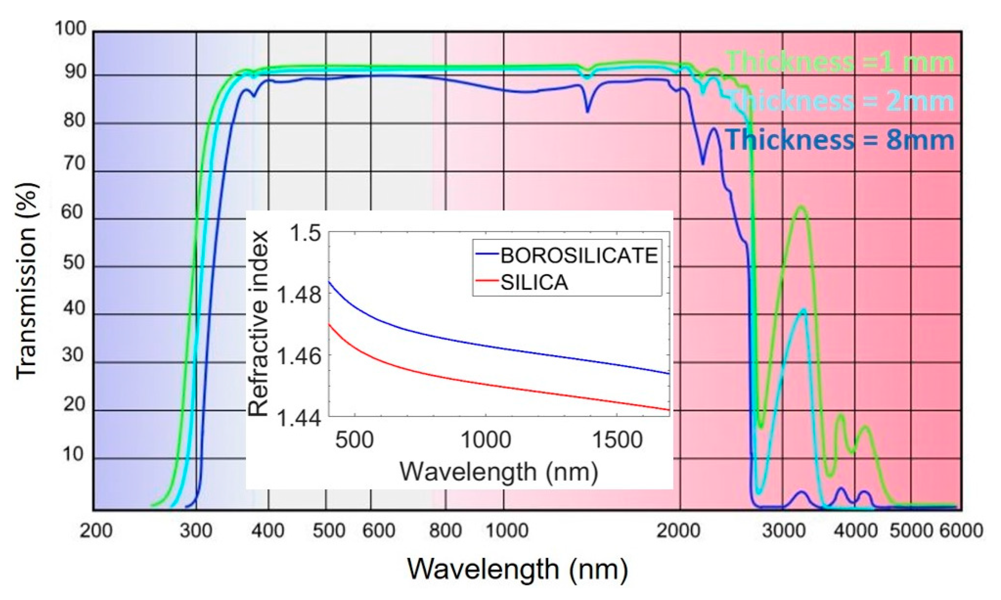
The optical transmission of the borosilicate glass used in this work (DURAN 8330) is shown in Figure 1 and taken from Reference [15] for different glass thicknesses. The inset of Figure 1 shows the comparison, in the visible and near-infrared spectral range, between the glass refractive index of DURAN 8330 (obtained by fitting the values obtained by borosilicate glass suppliers) and pure silica glass (obtained by using Sellmeier equations). By taking into account the refractive index change and the reflection at the glass/air interfaces [16], the attenuation of the DURAN 8330 can be evaluated to be about 40 dB/m at a wavelength of 1000 nm. This is over 4 order of magnitude greater than the attenuation of pure silica glass used currently in the production of conventional optical fibers [17].
Nevertheless, the much higher attenuation of the DURAN 8330 glass (even known under the trademark “Pyrex”) can actually become an advantage for the production of short length hollow-core optical fibers.
Firstly, the drawing temperature of borosilicate based optical fibers is around 900 °C, well below the 2000 °C required for silica-based optical fibers. This has some practical implications on the equipment used for optical fiber drawing, on the furnace type and basic elements, on its maintenance, on the cooling system, etc. All these factors make the overall equipment cost for fiber drawing significantly lower than what is needed for silica glass. Furthermore, purchased borosilicate glass tubes and rods used for the preform preparation of HCs [2] do not need to be prepared through refined glass preform processes (as Modified Chemical Vapor Deposition, MCVD) or extra purification steps [18], which would also add some relevant cost to the finalized product.
Secondly, in a conventional optical fiber, the fiber cladding is made of pure silica material with very low attenuation (below 1dB/km at 1000 nm), which demands some engineering strategies for limiting the transmission of optical cladding modes over short optical fiber lengths (while allowing efficient light guidance in the central germanium doped optical core). This issue is particularly relevant when simple devices using only few meters of fiber (or less) are implemented. When the optical source used is a laser, with high beam quality and low divergence, it is relatively easy to adopt optimized optical lenses for coupling the light within the optical fiber core and limiting light injection in the cladding. Since optical cladding modes are not excited, they cannot be guided. Moreover, the use of a high attenuation polymer-based fiber coating, with a refractive index higher than the one of silica, allows for the extinction of any residual cladding mode.
However, if an incoherent optical source with high divergence is used, it is particularly difficult to avoid the excitation of cladding modes. The use of incoherent sources in fiber optics applications may be driven mostly by the important economic benefit for the users over their coherent counterparts. For this same reason, one may want to interface directly the source and the fiber without any other additional optical component in order to keep the product price low. In this case, as depicted in the inset of Figure 2, an incoherent source generates a light cone that illuminates completely the transversal section of an optical fiber. If the cladding glass material has low attenuation, cladding modes will be guided over a length of several meters, despite the presence of the higher index external fiber coating. In contrast, if the cladding glass material is made of borosilicate glass, with intrinsically high attenuation (losses of tens of dB/m), the cladding modes will completely disappear after fiber lengths shorter than 30–40 cm.
These two reasons justify the development of the fabrication process of hollow-core optical fibers with a borosilicate glass cladding.
3. Near-Infrared Spectral Range
We have fabricated a large number of borosilicate based HCs for the visible and near-infrared spectral range. An adjustable induction furnace was used to allow the heating of the HC preform up to a temperature of 900 °C. The size of the furnace was chosen in order to allow an optimized laminar down-top argon gas flow within the furnace. This allowed a very stable drawing and the fabrication of optical fibers with a diameter uniformity below 0.5 μm and a standard deviation lower than 0.25. The uniformity of HC anti-resonant fibers is essential for achieving low attenuation and large operation bandwidth. The fabricated fibers were produced in lengths of several hundred meters, and they were coated with a standard Desolite 3471-3-14 fiber coating, applied through an unpressurized coating system with optimized concentricity. The HC fiber preforms were made by the conventional stack and draw technique [2]. The typical diameter for the starting preform was 19 mm, which was drawn to a cane diameter of few mm. The cane was then pressurized during fiber drawing by adopting two differential pressures for the core and fiber cladding. Although specific strength tests were not performed, the fabricated fibers were as handleable and robust as silica-based HCs when using them in our characterization experiments.
3.1. Attenuation
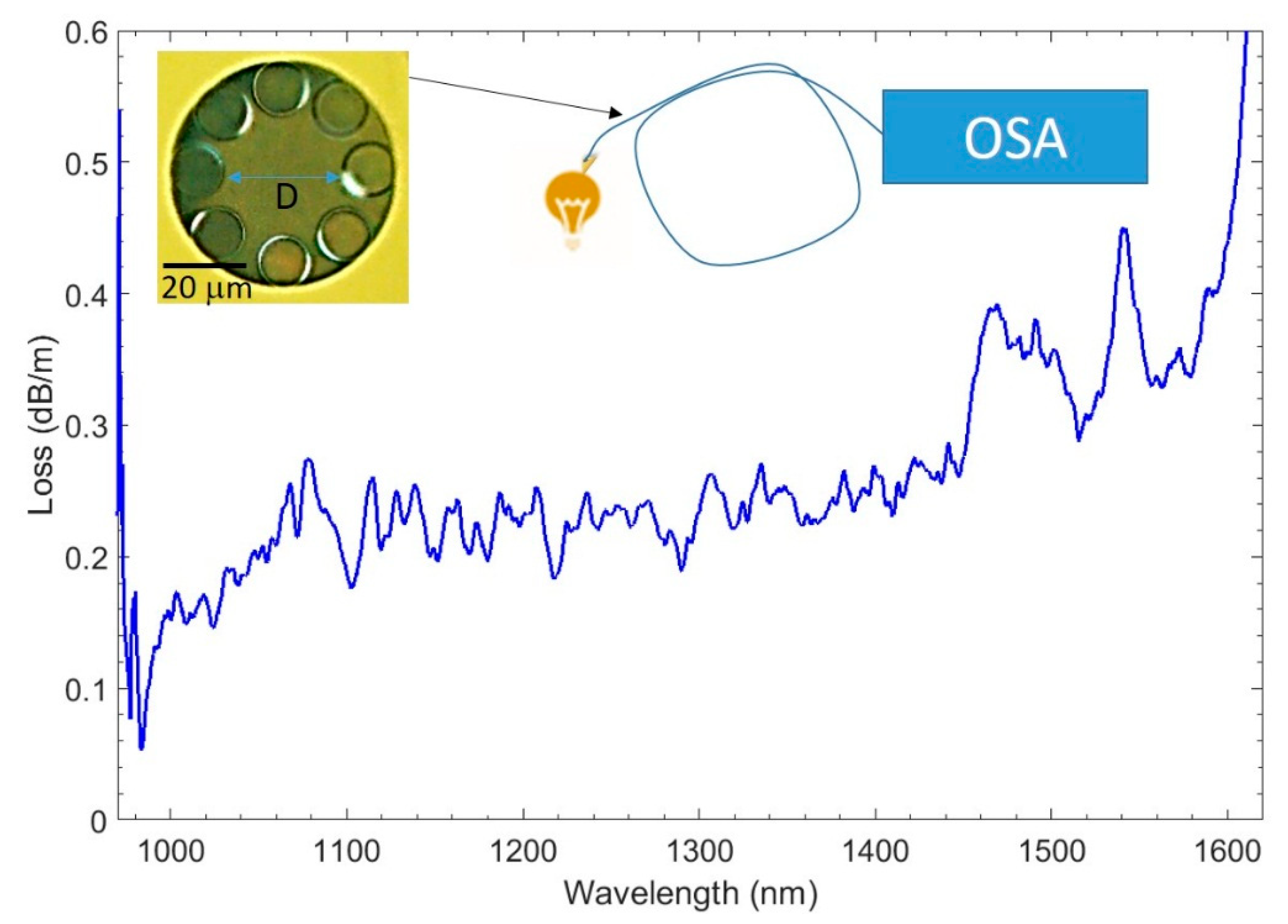
The minimum attenuation we obtained in the visible spectral range, at 532 nm, was 520 dB/km. We have then focused our work on the reduction of the attenuation in the near-infrared spectral range. Figure 2 shows the attenuation of the optical fiber shown in the inset.
This HC has an average core size D of 27 μm, cladding tube wall thickness of 0.45 μm, and an average separation between the cladding tubes of about 2.5 μm. The attenuation is obtained by a cut-back measurement from a length of 23.3 m to a final length of 5.3 m. A phosphor-coated CCD camera was used in combination with a 1540 nm optical source (with a bandwidth of 45 nm) to verify the single-mode operation of the fiber (and the absence of any cladding mode) even at a length of 1 m.
As depicted on the right-hand side of Figure 2, the attenuation measurements are made by using a broadband incoherent optical source directly linked to the fiber under test without any intermediate optical component. While the minimum of the attenuation curve, shown in Figure 2, was 53 dB/km at 983 nm (over a very narrow bandwidth), the loss was just above 200 dB/km over 400 nm spectral bandwidth. Note that the oscillation in the transmission spectrum, as well as some sharp attenuation peaks, are related to the mutual coupling between cladding modes and the fundamental-like mode in this transversally imperfect fiber, with minimal separation between some of the cladding tubes.
3.2. Bending Loss
The bending behavior of the fabricated fiber has been investigated. Figure 3 shows the recorded intensity (in dBm) of 1.7 m of the fiber shown in Figure 2 in three different configurations: when the fiber is not bent (blue line); when one full turn with a bending radius R of 10 cm is made (green line); and when two full turns with a R of 5 cm are made (red line). As we can see, for wavelength longer than 1000 nm, the fiber presents no relevant bending attenuation when R = 10 cm, while the bending loss for R = 5 cm are important and can be evaluated to be 5.3 dB/m at 1000 nm.
4. Mid-Infrared Spectral Range
We have fabricated borosilicate based optical fibers also for the mid-infrared spectral range. Pure silica and borosilicate glass have a similar attenuation at wavelengths above 5 μm (evaluated to be over 50,000 dB/m [19]). Therefore, our HC borosilicate fibers should expect to have similar performance to silica-based HCs within this spectral range, with the advantage of needing a less expensive material, equipment, and overall fabrication process. HC fibers for the mid-infrared have been reported with an attenuation of 0.085 dB/m at a wavelength of 4 μm [12]. This loss was limited by a silica glass material absorption of about 1000 dB/m at 4 μm. However, silica glass absorption rapidly increases at wavelengths above 4.5 μm [19]. At a wavelength of 5 μm, the glass absorption is over 50 times higher than at 4 μm. This is why no description of few meter long silica-based optical fiber working above the limit wavelength of 4.4 μm has ever been reported [20] (only some tens of cm samples of HCs were reported to have an attenuation of 30–50 dB/m in the 5.8–7.7 μm wavelength range [4]). However, we show here the fabrication of a borosilicate based HC operating at wavelengths above 5 μm.
4.1. Mid-IR Attenuation
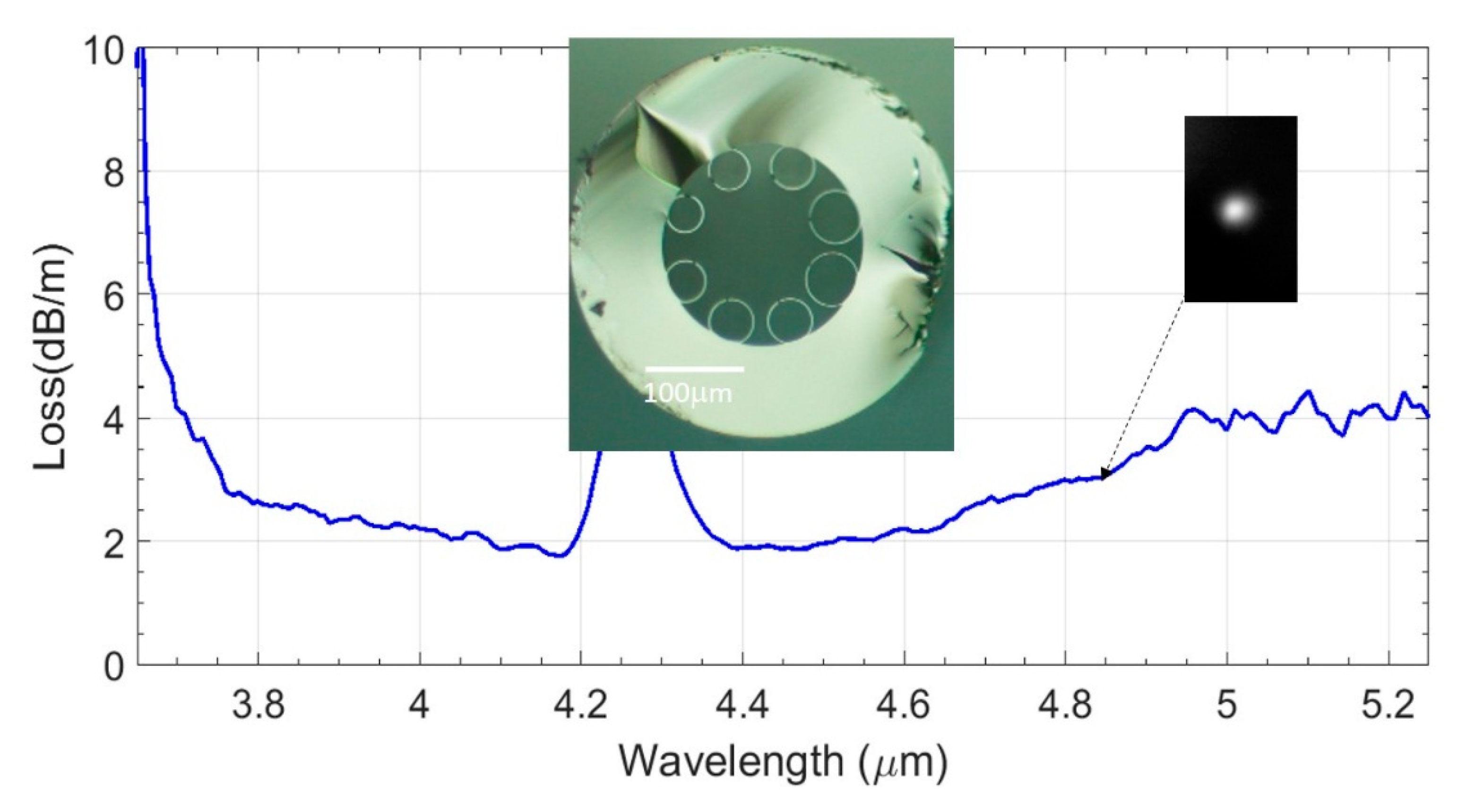
The fabricated borosilicate based HC is shown in the inset of Figure 4. The core size is 122 μm and the cladding tube wall thickness is about 1.4 μm. The cladding tubes have a mean diameter of 86 μm (with a standard deviation of 0.29). 23 m of this fiber were drawn at a constant fiber diameter of 400 μm. We can notice that, along the full fiber length, the HC presents a visible asymmetry in the size of the cladding tubes that we may relate to an unoptimized temperature profile within our induction furnace. Despite this imperfection, the cut-back measurements of this fiber, from a length of 2.51 m to a length of 0.71 m, reveal an attenuation of only 4 dB/m between 5 and 5.2 μm as shown in Figure 4, only 20 times higher than the minimum reported for a silica-based fiber at 4 μm.
The measurements were performed by using a stabilized broadband (450–5500 nm) fiber-coupled light source (from Thorlabs LTD, Ely, United Kingdom) and a mid-infrared spectrometer (anFT-IR Rocket for 2–6 μm wavelength detection range) (ARCoptix S.A, Neuchatel, Switzerland). The key factor for achieving this result was the ability to fabricate an HC for the mid-IR operating in the first anti-resonant optical window [21], thus having a ratio between the thickness of the cladding tube walls and the wavelength much lower than previously achieved (this ratio is about 0.88 in [14] and less than 0.35 in this work). Indeed, the material contribution to the HC attenuation is strictly dependent on the total amount of glass overlapping with the optical mode traveling in the fiber [21]. Figure 4 shows how the particular choice of the geometrical parameters determines an overall fiber loss limited by confinement losses up to the wavelength of 4.5 μm and then, beyond this, by an increasing glass absorption at longer wavelengths [19]. Consider that a more homogeneous transversal structure of the fiber would be beneficial for the attenuation in the wavelength region where leakage losses are predominant, but this is expected to have lower effects on the loss in the wavelength region above 4.5 μm where the material component of the attenuation is predominant. Note also that the strong absorption around 4.2 μm is related to the presence of atmospheric CO2 within the fiber under test. This is despite a maximum volume of air inside the HC of approximately V = π r2 h = 7.85 × 10⁻⁸ m3 which, given an atmospheric CO2 concentration of 410 ppm, equates to only 8 × 10¹⁴ CO2 molecules, some 12 orders of magnitude lower than those in a single exhaled breath. The inset on the right-hand side of Figure 4 shows the image of the single optical mode traveling within the fiber at a wavelength between 4.75 μm and 4.9 μm. This was obtained by using 1.8 m of fiber, a mid-infrared camera with a detection wavelength range up to 4.9 μm, and a band-pass filter centered at 5 μm (with a bandwidth of ±0.25 μm). The measurement of the attenuation spectrum was limited by both the performance of the broadband mid-IR optical source and of the spectrum analyzer.
4.2. Mid-IR Bending Loss
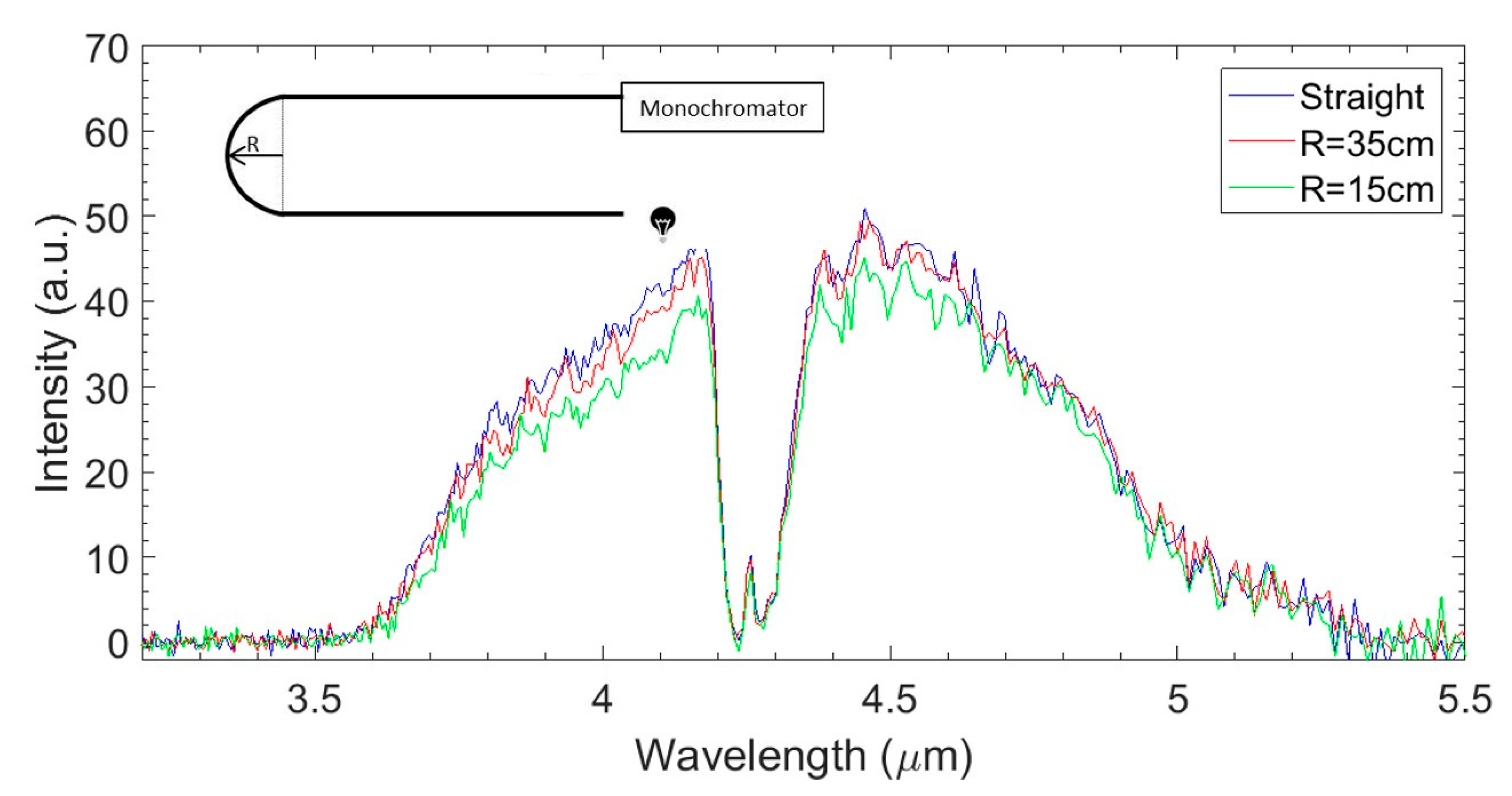
The bending characteristics of the fabricated fibers are of major importance given the long wavelength range of operation and their large core size. It allows to evaluate to which extent these HCs can be used in real applications, such as mid-infrared optical beam delivery. In the inset of Figure 5, the experimental setup used for the bending measurements is shown. The broadband stabilized source is directly connected to 1.3 m of the fiber under test. Three measurements are made with the fiber straight (blue line) and bent with a radius R of 35 cm (red line) or of 15 cm (green line) over half a full turn. The results demonstrate a very good bending resistance at R = 35 cm. The attenuation increases rapidly in the shorter wavelength side of the spectrum when the fiber bend radius decreases to 15 cm (this is almost equivalent, for example, to a standard fiber drum with a circumference of 1 m). However, the bending attenuation only affects the part of the spectrum where leakage loss is the predominant attenuation factor. For wavelengths longer than 4.5 μm, no bending attenuation is observed, even with a bending radius of 15 cm. When compared with bend resistant silica HC fibers used for the implementation of acetylene gas lasers at 3.16 μm [11,22], we can see that this borosilicate based HC fiber has worse bending performances around the wavelength of 4.5 μm (about 0.6 dB/m for R = 15 cm, as compared to 0.3 dB/m for R = 7.96 cm in [22]) but, arguably, still satisfactory for its practical use.
5. Conclusions
We have reported the fabrication of hollow-core optical fibers made ofborosilicate glass with relatively high optical absorption. In the near-infrared spectral range, an attenuation just above 0.2 dB/m over 400 nm spectral bandwidth has been measured (with a minimum of the attenuation curve below 0.1 dB/m), while in the mid-infrared, an attenuation of 4 dB/m has been measured between 5 and 5.2 μm. The reported bending attenuation at wavelengths of both 1 and 5 μm is negligible for applications requiring a bending radius higher than 10 cm. Borosilicate based HCs could be implemented in devices requiring short fiber lengths, by only using incoherent optical sources and no additional optical components, resulting in a cost-effective solution.
Author Contributions
W.B. conceived the work, fabricated the optical fibers, made the measurements, and wrote the manuscript. P.J.S. supported this project, discussed the results, and reviewed the manuscript.
Funding
This research received no external funding.
Acknowledgments
The authors would like to thank Joris Lousteau for several very inspiring discussions and technical advice.
Conflicts of Interest
The authors declare no conflict of interest.
References
- Belardi, W. Hollow-core optical fibers. Fibers 2019, 7, 50. [Google Scholar] [CrossRef]
- Bufetov, I.A.; Kosolapov, A.F.; Pryamikov, A.D.; Gladyshev, A.V.; Kolyadin, A.N.; Krylov, A.A.; Yatsenko, Y.P.; Biriukov, A.S. Revolver Hollow Core Optical Fibers. Fibers 2018, 6, 39. [Google Scholar] [CrossRef]
- Pryamikov, A.D.; Biriukov, A.S.; Kosolapov, A.F.; Plotnichenko, V.G.; Semjonov, S.L.; Dianov, E.M. Demonstration of a waveguide regime for a silica hollow-core microstructured optical fiber with a negative curvature of the core boundary in the spectral region >3.5 μm. Opt. Express 2011, 19, 1441. [Google Scholar] [CrossRef] [PubMed]
- Kolyadin, A.N.; Kosolapov, A.F.; Pryamikov, A.D.; Biriukov, A.S.; Plotnichenko, V.G.; Dianov, E.M. Light transmission in negative curvature hollow core fiber in extremely high material loss region. Opt. Express 2013, 21, 9514. [Google Scholar] [CrossRef] [PubMed]
- Debord, B.; Amrani, F.; Vincetti, L.; Gérôme, F.; Benabid, F. Hollow-Core Fiber Technology: The Rising of “Gas Photonics”. Fibers 2019, 7, 16. [Google Scholar] [CrossRef]
- Belardi, W.; Knight, J.C. Negative curvature fibers with reduced leakage loss. Opt. Soc. Am. 2014, Th2A.45. [Google Scholar] [CrossRef] [Green Version]
- Belardi, W.; Knight, J.C. Hollow antiresonant fibers with reduced attenuation. Opt. Lett. 2014, 7, 1853. [Google Scholar] [CrossRef] [PubMed]
- Van Putten, L.D.; Fokoua, E.N.; Mousavi, S.M.A.; Belardi, W.; Chaudhuri, S.; Badding, J.V.; Poletti, F. Exploring the Effect of the Core Boundary Curvature in Hollow Antiresonant Fibers. IEEE Photonics Technol. Lett. 2016, 2, 263. [Google Scholar] [CrossRef]
- Belardi, W.; De Lucia, F.; Poletti, F.; Sazio, P.J. Composite material hollow antiresonant fibers. Opt. Lett. 2017, 13, 2535. [Google Scholar] [CrossRef] [PubMed]
- Bateman, S.A.; Belardi, W.; Yu, F.; Webb, C.E.; Wadsworth, W.J. Gain from helium-xenon discharge in hollow optical fibres at 3 to 3.5 µm. Opt. Soc. Am. 2014, STh5C. [Google Scholar] [CrossRef]
- Abu Hassan, M.R.; Yu, F.; Wang, Z.; Belardi, W.; Wadsworth, W.J.; Knight, J.C. Synchronously pumped mid-IR hollow core fiber gas laser. In Proceedings of the 2015 Conference on Lasers and Electro-Optics, San Jose, CA, USA, 10–15 May 2015. [Google Scholar]
- Gattass, R.R.; Rhonehouse, D.; Gibson, D.; McClain, C.C.; Thapa, R.; Nguyen, V.Q.; Bayya, S.S.; Weiblen, R.J.; Menyuk, C.R.; Shaw, L.B.; et al. Infrared glass-based negative-curvature anti-resonant fibers fabricated through extrusion. Opt. Express 2016, 24, 25697. [Google Scholar] [CrossRef] [PubMed]
- Cruz, A.L.S.; Cordeiro, C.M.B.; Franco, M.A.R. 3D Printed Hollow-Core Terahertz Fibers. Fibers 2018, 6, 43. [Google Scholar] [CrossRef]
- Yu, F.; Knight, J.C. Spectral attenuation limits of silica hollow core negative curvature fiber. Opt. Express 2013, 21, 21466. [Google Scholar] [CrossRef] [PubMed]
- Continental Trade. Available online: https://www.continentaltrade.com.pl/borosilicate-glass (accessed on 1 August 2019).
- Schott. Available online: https://www.schott.com/advanced_optics (accessed on 1 August 2019).
- Humbach, O.; Fabian, H.; Grzesik, U.; Haken, U.; Heitmann, W. Analysis of OH absorption bands in synthetic silica. J. Non-Cryst. Solids 1996, 203, 19. [Google Scholar] [CrossRef]
- Mendez, A.; Morse, T.F. Specialty Optical Fibers Handbook; Academic Press: Cambridge, MA, USA, 2007. [Google Scholar]
- Kitamura, R.; Pilon, L.; Jonasz, M. Optical constants of silica glass from extreme ultraviolet to far infrared at near room temperature. Appl. Opt. 2007, 33, 8118. [Google Scholar] [CrossRef] [PubMed]
- Gladyshev, A.V.; Kosolapov, F.; Astapovich, M.S.; Kolyadin, A.N.; Pryamikov, A.D.; Khudyakov, M.M.; Likhachev, M.E.; Bufetov, I.A. Revolver Hollow-Core Fibers and Raman Fiber Lasers. In Proceedings of the 2018 Optical Fiber Communications Conference and Exposition, San Diego, CA, USA, 11–15 March 2018. [Google Scholar]
- Belardi, W. Design and Properties of Hollow Antiresonant Fibers for the Visible and Near Infrared Spectral Range. J. Lightwave Technol. 2015, 21, 21–4497. [Google Scholar] [CrossRef]
- Belardi, W.; Knight, J.C. Hollow antiresonant fibers with low bending loss. Opt. Express 2014, 22, 10091. [Google Scholar] [CrossRef] [PubMed]
Figure 1.
Transmission of DURAN 8330 glass for different glass thicknesses. Inset: comparison between refractive index of borosilicate and pure silica glass in the visible and near-infrared spectral range.
Figure 1.
Transmission of DURAN 8330 glass for different glass thicknesses. Inset: comparison between refractive index of borosilicate and pure silica glass in the visible and near-infrared spectral range.

Figure 2.
Attenuation of a borosilicate based hollow-core optical fiber (shown in the inset on the left-hand side). On the right-hand side is a sketch of the measurement setup including only an incoherent optical source, a loosely cooled fiber, and an optical spectrum analyzer (OSA). Fiber loss is just above 0.2 dB/m over a 400 nm wide spectral bandwidth.

Figure 3.
Comparison of the optical transmission spectrum of 1.7 m of borosilicate based hollow-core optical fibers (HC), for different bend radii R: loosely coiled fiber (blue line), R = 10 cm (green line, 1 full turn) and R = 5 cm (red line, 2 full turns).
Figure 3.
Comparison of the optical transmission spectrum of 1.7 m of borosilicate based hollow-core optical fibers (HC), for different bend radii R: loosely coiled fiber (blue line), R = 10 cm (green line, 1 full turn) and R = 5 cm (red line, 2 full turns).

Figure 4.
Attenuation spectrum for the HC optical fiber shown in the inset. The attenuation between 5 and 5.2 μm is 4 dB/m. The inset on the right-hand side shows the optical mode image within the wavelength range 4.75–4.9 μm.
Figure 4.
Attenuation spectrum for the HC optical fiber shown in the inset. The attenuation between 5 and 5.2 μm is 4 dB/m. The inset on the right-hand side shows the optical mode image within the wavelength range 4.75–4.9 μm.

Figure 5.
Optical transmission spectrum of 1.3 m of the HC of Figure 4, when the fiber is straight (blue line), bent with a bending radius R of 35 cm (red line, half a turn) and with R = 15 cm (green line, half a turn).
Figure 5.
Optical transmission spectrum of 1.3 m of the HC of Figure 4, when the fiber is straight (blue line), bent with a bending radius R of 35 cm (red line, half a turn) and with R = 15 cm (green line, half a turn).

© 2019 by the authors. Licensee MDPI, Basel, Switzerland. This article is an open access article distributed under the terms and conditions of the Creative Commons Attribution (CC BY) license (http://creativecommons.org/licenses/by/4.0/).
Share and Cite
MDPI and ACS Style
Belardi, W.; Sazio, P.J. Borosilicate Based Hollow-Core Optical Fibers. Fibers 2019, 7, 73. https://0-doi-org.brum.beds.ac.uk/10.3390/fib7080073
AMA Style
Belardi W, Sazio PJ. Borosilicate Based Hollow-Core Optical Fibers. Fibers. 2019; 7(8):73. https://0-doi-org.brum.beds.ac.uk/10.3390/fib7080073
Chicago/Turabian StyleBelardi, Walter, and Pier John Sazio. 2019. "Borosilicate Based Hollow-Core Optical Fibers" Fibers 7, no. 8: 73. https://0-doi-org.brum.beds.ac.uk/10.3390/fib7080073
Note that from the first issue of 2016, this journal uses article numbers instead of page numbers. See further details here.