Flexural Behavior of Hybrid-Reinforced Concrete Exterior Beam-Column Joints under Static and Cyclic Loads

Civil Engineering Department, Babylon University, Babylon 11702, Iraq
*
Author to whom correspondence should be addressed.
Fibers 2019, 7(10), 94; https://0-doi-org.brum.beds.ac.uk/10.3390/fib7100094
Submission received: 31 August 2019
/
Revised: 14 October 2019
/
Accepted: 20 October 2019
/
Published: 22 October 2019
(This article belongs to the Special Issue Application of Fiber Reinforced Polymers in Strengthening of Reinforced Concrete Structures)
Abstract
:This study presents an experimental investigation of the flexure behavior of exterior beam-column joints made from hybrid concrete (normal concrete (NC) and reactive powder concrete (RPC)) or hybrid reinforcement (steel and carbon fiber reinforced polymer (CFRP) bars internally or externally by near surface mounted (NSM) technique). Nine hybrid-reinforced concrete beam-column joint specimens under the effect of static or cyclic loading were studied and tested within three test groups. Several variables that affect the behavior of the beam-column joint region are investigated such as: type of loading (static or cyclic), type of hybridization (concrete hybridization or reinforcement hybridization), and area of concrete hybridization. The results showed that using RPC as a replacement concrete at different areas of beam-column joint under static loading improved the ultimate load capacity and first cracking load to about 8–32% and 20–60%, respectively, compared with the reference NC joint with increase in the ductility of about 6–14%. Moreover, using the same technique under cyclic loading condition showed an increase in the ultimate load of about 39%, with improvement in the cumulative ductility of about 12% compared with the reference NC joint. On the other hand, using CFRP bars as (internal or external) hybridization system (33% of main reinforcement) under static loading caused increments of ultimate and first cracking loads of about 11%, 8% and 0%, 30%, respectively compared with the reference steel reinforced joint; while the ductility ratio increased about 36%, 5%, respectively. Moreover, the internal hybrid reinforcement system exhibited a decrease in the ultimate load of about 15% and reduction in the cumulative ductility of about 40% under cyclic loading.
1. Introduction
The beam-column joint is defined as the portion of the column within the depth of the deepest beam that frames into the column [1]. Beam-column joints in a reinforced concrete moment resisting frames are critical areas for exchange of loads adequately between the associating components (i.e., columns and beams) in the building and ensure its continuity [2]. The change suddenly in the geometry and the complex nature of stress distribution in the joint are the explanations behind their critical conduct. The joints have limited ultimate carrying capacity; therefore, when they are subjected to greater forces during earthquakes or blasts, joints are severely damaged and may lead to catastrophic failure of the entire building. Repairing damaged joints is difficult, thus damage should be avoided. Therefore, beam-column connections ought to have sufficient strength, ductility, and energy dissipation to oppose the inside forces caused by the framed members [3]. Since the 1960s, many experimental and theoretical investigations have been conducted to investigate the overall conduct of BCJ. The examinations for the conduct of hybrid-reinforced concrete construction generally started at the end of the last century. Numerous researches have examined the conduct and quality of hybrid-reinforced concrete members with different hybridization techniques.
Leung and Balendran [4] showed experimental investigation of the load-deflection conduct for the concrete beams reinforced internally by steel bars and glass fiber-reinforced polymer (GFRP) rods. In view of the test outcomes, the bending quality of hybrid-reinforcement beams is higher than the concrete beams combined with any steel reinforcement bars or GFRP rods. Raj and Jeen [5] studied the conduct of hybrid beams containing conventional concrete and ultrahigh performance concrete. They found that the hybrid beams have the ability to resist high loads. Also, the deflections of the hybrid beams were marginally lower than that of the reference beam. Mahdi [6] investigated the conduct and extreme strength of concrete corbels with hybrid reinforcement (CFRP and steel) rebars subjected to vertical distributed applied load. He found great enhancement in the conduct and the ultimate strength of the specimens with hybridization technique of main tension reinforcement and also horizontal reinforcement (closed stirrups).
It can be noticed from literature that the hybridization systems of concrete or reinforcement were extensively studied for the ordinary beams, corbels, and other structural members but, there are few studies on the flexural conduct of hybrid-reinforced BCJs. Therefore, the current study contributes to increasing the knowledge of the conduct of hybrid-reinforced concrete exterior BCJs under the effect of static or cyclic loading.
The target of this work is to conduct an experimental investigation of the ultimate strength, cracking patterns, failure patterns, ductility, and energy absorption of reinforced concrete exterior BCJs made of hybrid concrete or hybrid reinforcement; and to study the factors that influence the flexural behavior of the hybrid BCJs, such as type of loading (static or cyclic), type of hybridization (concrete hybridization or reinforcement hybridization), and area of concrete hybridization.
2. Test Program
2.1. Description of Specimens
The tested reinforced concrete joint specimens were made of either conventional or hybrid concrete (i.e., replacement of conventional concrete by reactive powder concrete at different zones of joint) or hybrid reinforcement (i.e., replacement of steel bars by CFRP bars of internally or externally locations).
All joints are designed to fail in bending before shear in accordance with the design provisions of (ACI-ASCE 352-02) and (ACI-Code 318-14) for Type1 exterior connection [7]. The test program included examining the use of three main groups, I, II, and III; they were hybrid concrete under static loading, hybrid reinforcement under static loading, and hybrid concrete or hybrid reinforcement under cyclic loading, respectively. For three groups, nine specimens of BCJ were tested and the main variables were the type of hybridization (concrete or reinforcement), area of concrete hybridization, and type of loading (static or forward cyclic). Figure 1 illustrates the naming convention utilized to determine the exterior beam-column connection specimens. Designation and details of the tested BCJ specimens are reported and displayed in Table 1.
The geometry of the specimens was comparable; total height of column and cross-section dimensions were 1300 mm and (160 × 300) mm, respectively, while the length of beam and cross-section dimensions were 600 mm and (160 × 240) mm, respectively. The concrete covers were about 20 mm of the column, 25 mm of the upper and the lower sides of the beam, and 32 for the other sides of the beam. The end of the beam extended 100 mm beyond the support centerline. Geometry and detailed reinforcement arrangement of the joint specimens are presented in Table 2 and appeared in Figure 2 and Figure 3.
2.2. Material Properties
Ordinary Portland cement was utilized in casting all the specimens and it is commercially known by the name LION. Regular sand from AL-AKAIDUR locale was utilized as fine aggregate with maximum size aggregate of 4.75 mm for NC and 0.6 mm for RPC. Locally available gravel of 14 mm most extreme size was utilized in normal concrete. Type WSF0213 micro steel fiber was utilized in RPC with aspect ratio (Lf/Df = 65) and it was manufactured by a company in the Jiangxi province, China according to ASTM A820-11 [8]. Grey densified silica fume (MEYCO MS610) from the Chemical Company (BASF) was used in RPC. Normal concrete (NC) was utilized to cast all the specimens with various areas. Reactive powder concrete (RPC) (with micro steel fiber 1% of volume percent) was used for the hybridization purpose with different areas. Superplasticizer (Sika Viscocrete 5930-L) was employed for both mixes to give an adequate strength and workability. Several trial mixes were made and tested at ages 7 and 28 days. The compressive strength at age 28 days was around 30 MPa for NC and 120 MPa for RPC. Table 3 shows the selected mixtures. The yield strength of steel (fy) of bars ø6, ø10, ø12, and ø16 mm was 520, 464, 486, and 516 MPa, respectively. The Aslan 200/201 CFRP bar (ø6mm) was used as the hybrid main reinforcement and its properties were as measured by the manufacturer (Hughes Brothers, China 2010) [9]. Epoxy resin (Sikadur-30) manufactured by Sika Company was employed in this work.
2.3. Test Setup
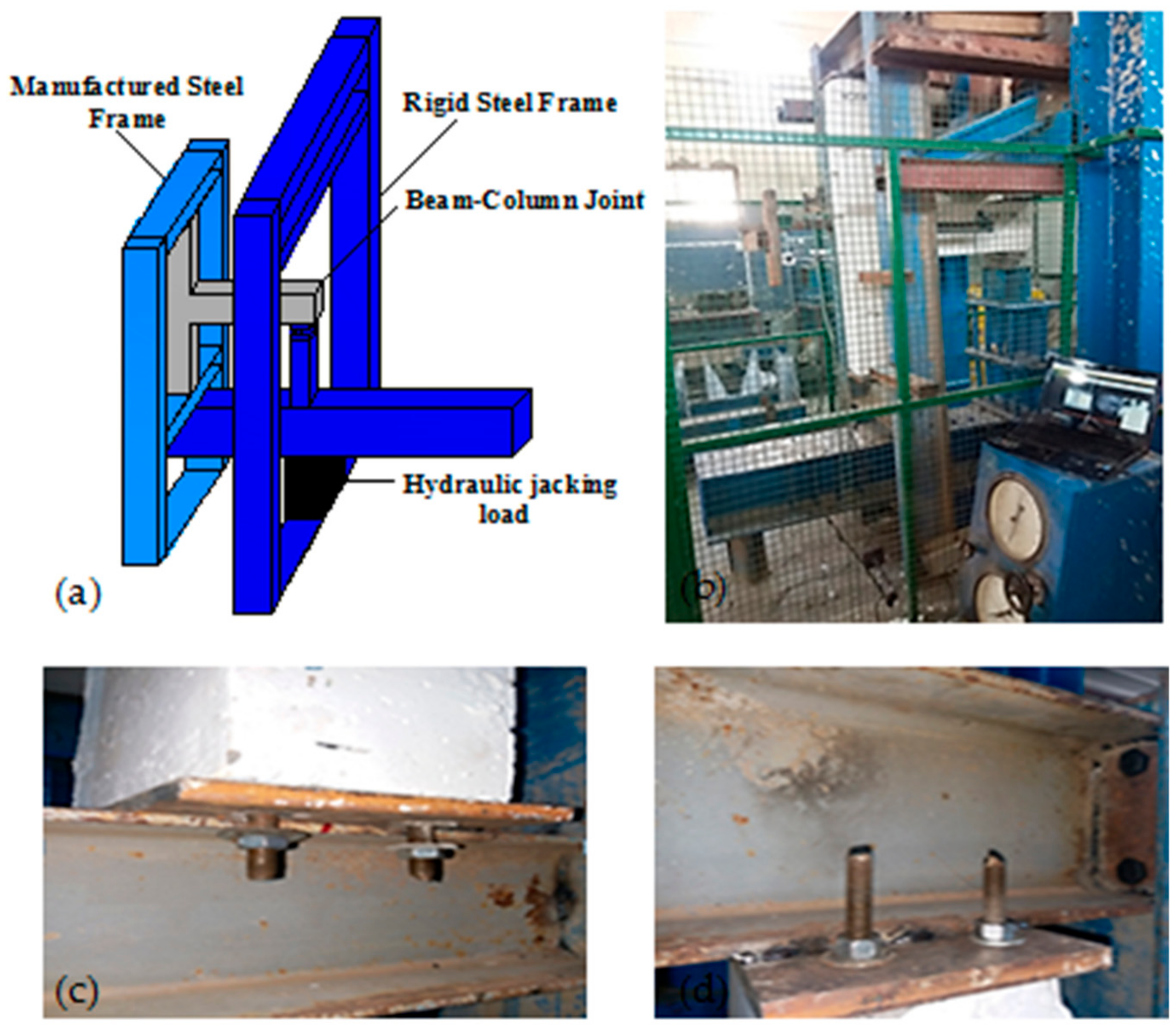
The hydraulic universal testing machine was utilized to test the BCJ specimens and also the control specimens. The testing machine has a limit of 1000 kN available in the Structural Laboratory in Civil Engineering Department, Faculty of Engineering, University of Kufa. The machine was modified from testing beams to test the external BCJs within the locally available possibilities by manufacturing an additional frame for fixing the ends of the column, as shown in Figure 4.
2.4. Test Procedure
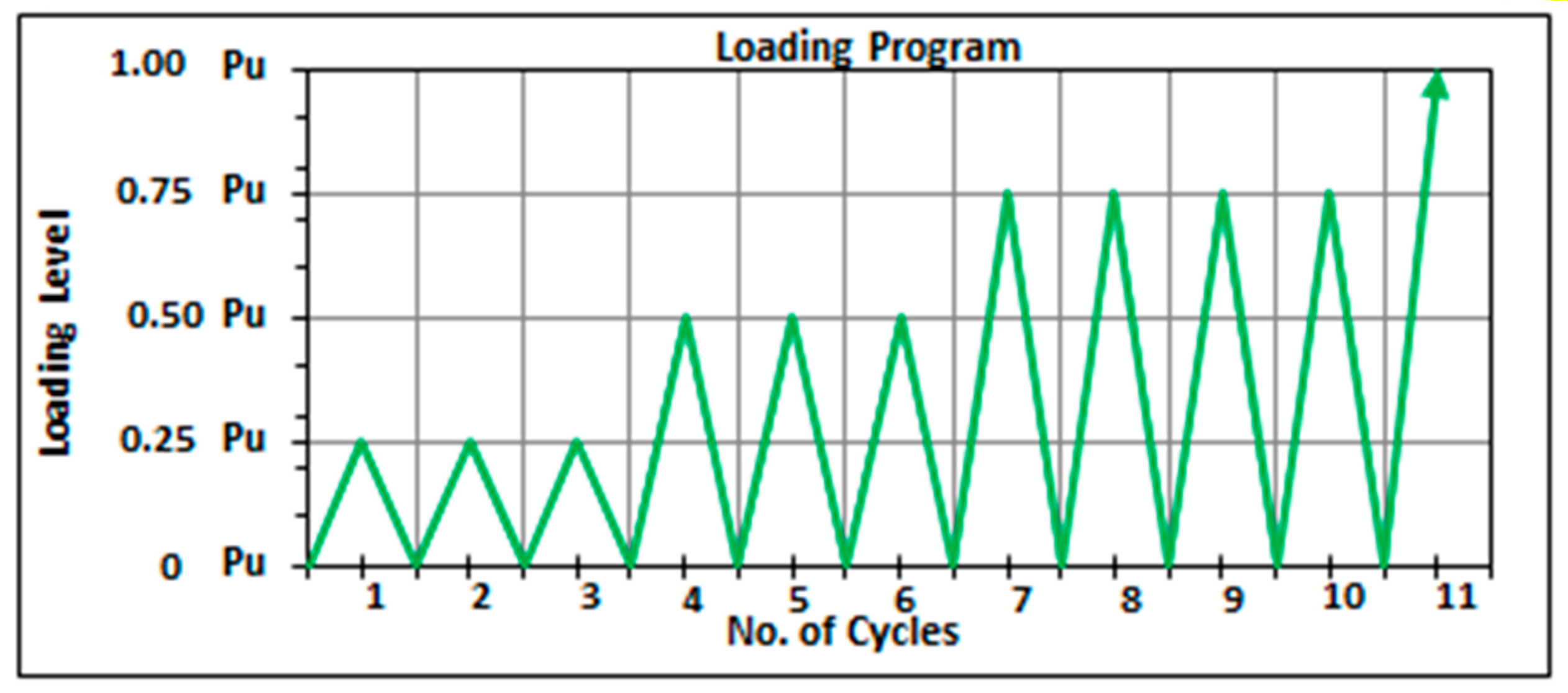
All specimens were tested in an inverted position where they were exposed to the vertical load at the bottom end of the beam and fixed by two supports at the end of the column, as shown in Figure 4. First, the specimen was loaded with 5 kN to seal the supports and the system of loading, then unloading to zero. Subsequently, the load increment was 10 kN along the static loaded specimens test and the deflection was measured at every load step by a dial gauge which was installed at the free end of the beam. For specimens subjected to forward cyclic loading, they were tested according to the loading program based on the static loads for similar specimens, as shown in Figure 5.
3. Results and Discussion
The experimental results of the tested homogenous and hybrid-reinforced concrete joints were compared to study the influence of using hybrid concrete or hybrid reinforcement system on the flexural conduct of exterior BCJs.
3.1. Cracking and Ultimate Loads and Failure Modes
Table 4 shows a synopsis of the experiential results and the discussion of them is displayed in the accompanying parts. These results include, first cracking load of flexural and shear cracks, ultimate loads and their increasing percentages compared with the reference specimens for the tested BCJ specimens.
In the experiment, it was found that the specimen suffered from the formation of both the flexural and shear cracks, and the first major crack appeared at the intersection plane of the beam with column. Figure 6 presents a load-deflection response of all specimens and Figure 7 illustrates the failure mode and cracking patterns of them.
3.1.1. Group I (BCJs with Hybrid Concrete)
In this test group, an endeavor to improve the flexure conduct of beam-column joints is done by fabricating hybrid system comprising normal concrete and reactive powder concrete at different areas of joint, see Figure 2. Hybrid system is compared with homogenous joint (i.e., the reference specimen BCJ1.F.N.S which made from normal concrete only and designed to fail in flexure) to consider the impact of concrete hybridization on the flexure conduct of exterior BCJ under static loading.
This type of hybridization for specimens (BCJ2.F.HC1.S, BCJ3.F.HC2.S and BCJ4.F.HC3.S) caused an increase in first cracking and ultimate loads of about 20–60% and 8–32%, respectively, compared with the reference NC joint specimen. The failure mode of this group included basically flexural crack followed by shear crack for all specimens.
3.1.2. Group II (BCJs with Hybrid Reinforcement)
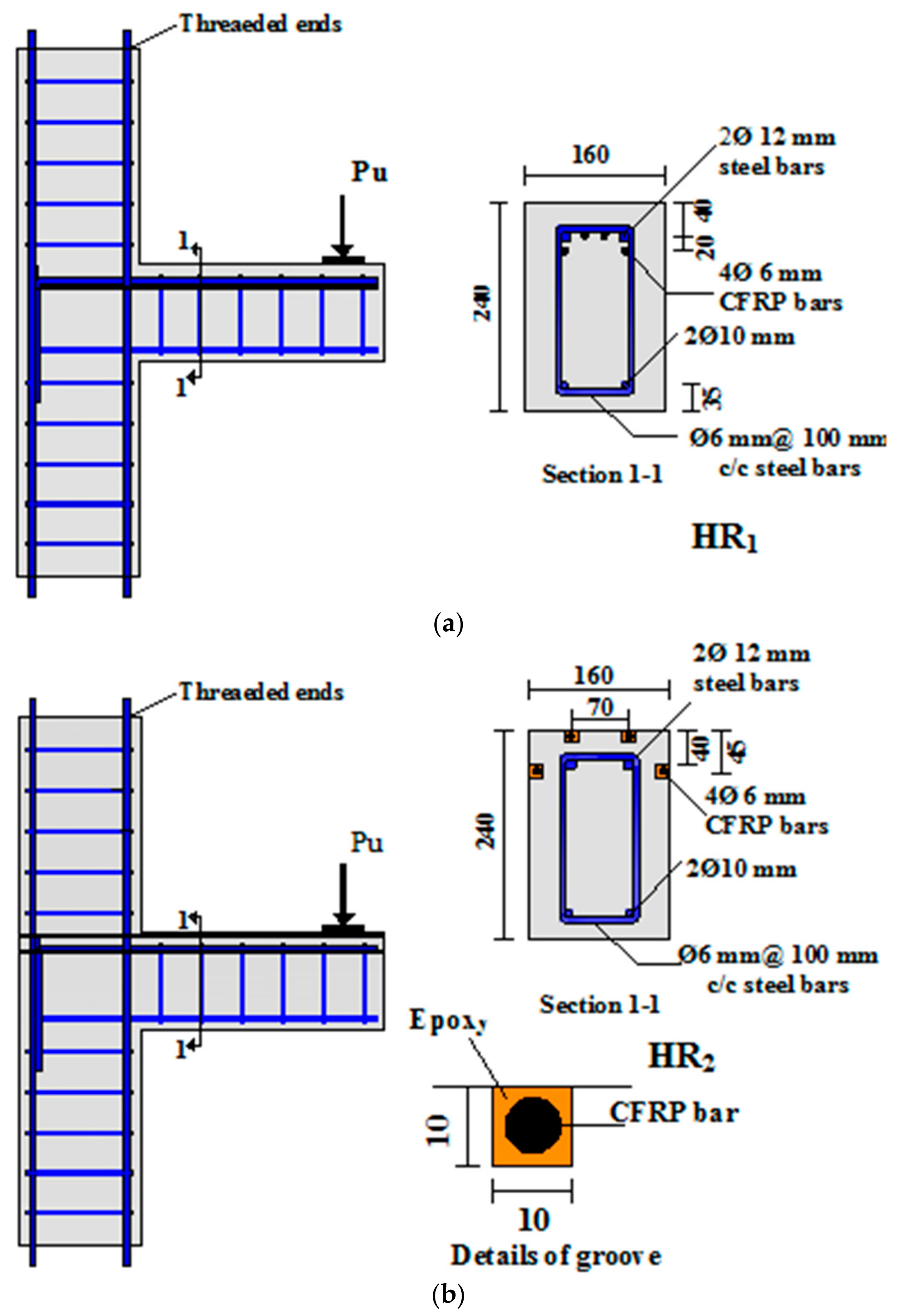
Through this test group, two specimens are fabricated from one type of concrete (NC) with an idea of hybrid main reinforcement system that comprised of steel bars and CFRP bars internally or externally by NSM technique, see Figure 3. This system of hybridization is compared with ordinary joint (i.e., the reference specimen (BCJ1.F.N.S) which is reinforced by steel only and designed to fail in flexure) to consider the impact of the hybrid reinforcement technique on the flexure conduct of the exterior BCJ under static loading.
Using CFRP bars as 33% internal main reinforcement in tension zone of beam section (for specimen BCJ5.F.HR1.S) did not improve the first cracking load but increased the ultimate load about 11% compared to the reference specimen. Beam flexural failure occurred for this specimen. On the other hand, using CFRP bars as 33% external main reinforcement by NSM technique in tension zone of beam section (for specimen BCJ6.F.HR2.S) showed an increase in the first cracking and ultimate loads of about 30% and 8%, respectively compared with the reference specimen. Then, CFRP bar debonding in one side of the beam occurred for this specimen, followed by beam flexure failure.
3.1.3. Group III (BCJs under Cyclic Loading)
In this group, three beam-column joint specimens were made from either hybrid concrete (NC and RPC) or hybrid reinforcement (steel and CFRP bars internally as main reinforcement), see Figure 2 and Figure 3. They were exposed to cyclic loading to study the conduct under cyclic loading, as shown in Figure 5.
The specimen with normal concrete (BCJ7.F.N.C) is considered as reference specimen for the third test group that was designed for flexure failure. The first crack formed early, as well as the ultimate load decreased about 20% because of the cyclic loading which caused reduction in the joint stiffness compared with the same specimen under static loading condition (BCJ1.F.N.S) and the mode of failure was flexure tension failure.
For specimen with hybrid concrete (NC and RPC) (BCJ8.F.HC2.C), the ultimate load was 8% less than the same specimen under static loading (BCJ3.F.HC2.S), but it was 39% more than the reference joint (BCJ7.F.N.C). The mode of failure was flexure tension failure.
For specimen with hybrid reinforcement (steel and CFRP bars internally as 33% main reinforcement) (BCJ9.F.HR1.C), the ultimate load was 39% less than the same specimen under static loading (BCJ5.F.HR1.S) because of fatigue in the joint under cyclic loading condition. On the other side, the first cracking load was equal to the reference specimen (BCJ7.F.N.C); while, the ultimate load was reduced to about 15%. The mode of failure was flexure failure. This means that, the internal hybrid reinforcement as main reinforcement gave lesser ultimate load than the reference specimen because of low stiffness in the CFRP bars.
3.2. Ductility
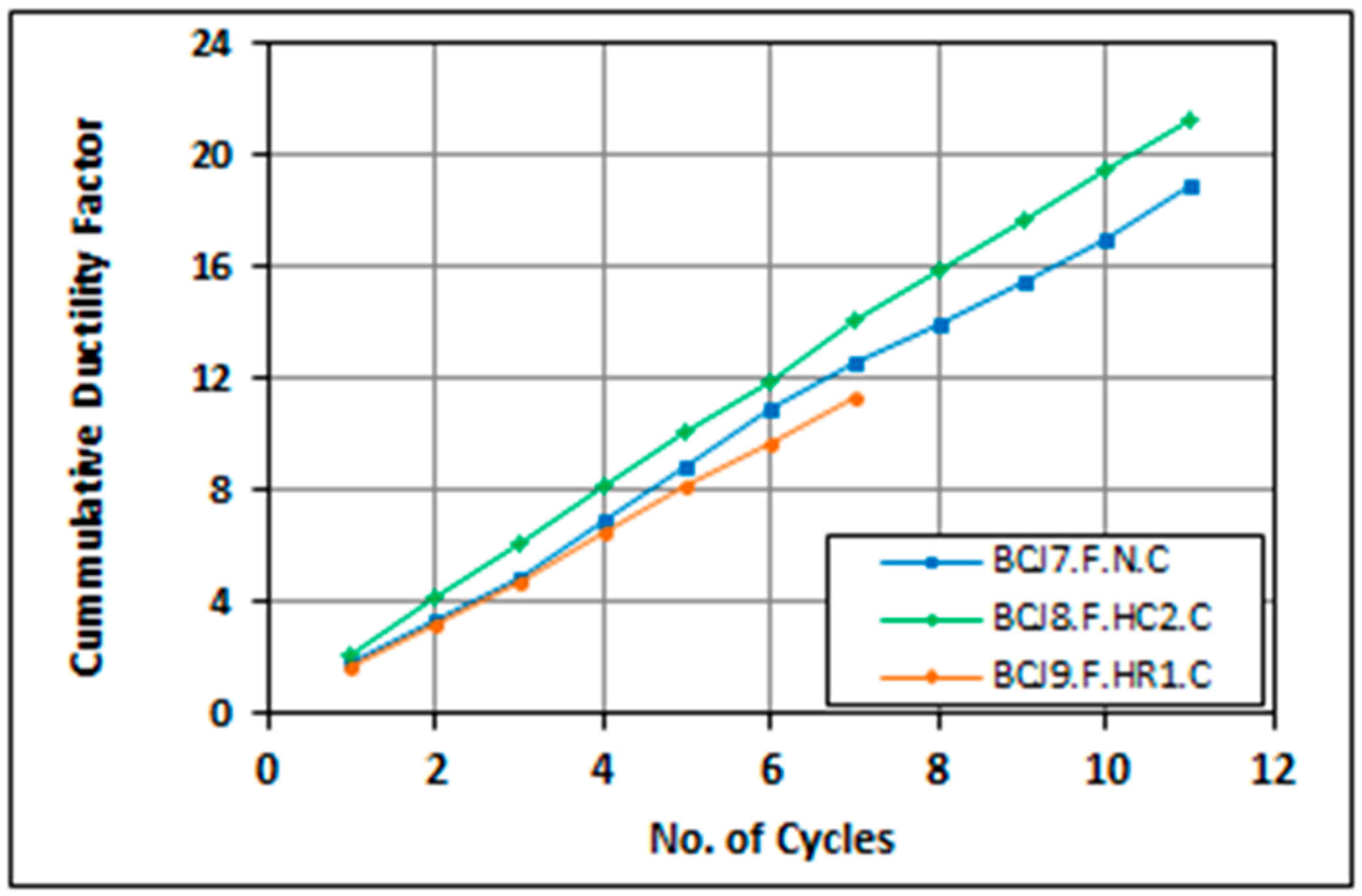
Ductility is defined as the energy absorbed by the materials until failure has been achieved [10]. In the current study, ductility ratios are assessed according to the vertical displacement at maximum load divided by the vertical displacement at the service load (approximately 65% of maximum load) [11]. Also, the experimental cumulative ductility values are investigated for all specimens that are subjected to forward cyclic loading. The cumulative ductility is defined, at any load point, as the sum of the ductility at greatest load level accomplished in every cycle until the cycle considered [12]. In general, the specimens with hybrid concrete and that are subjected to static loading (BCJ2.F.HC1.S, BCJ3.F.HC2.S and BCJ4.F.HC3.S) exhibit higher ductility factor of about 6%, 14%, and 9% than the reference specimen (BCJ1.F.N.S), respectively, because of high ductility of reactive powder concrete. On the other hand, the specimen with reinforcement hybridization technique by using CFRP bars as (internal or external) the main reinforcement (BCJ5.F.HR1.S and BCJ6.F.HR2.S) showed an increase in ductility of about 36% and 5% compared to that of the reference specimen (BCJ1.F.N.S), because of low modulus of elasticity of CFRP bars which produced higher ultimate deflection. The cumulative ductility values for the cyclic loaded joints (BCJ8.F.HC2.R and BCJ9.F.HR1.C) were increased to about 12% for the first joint and reduced to about 40% for the other joint, compared to the homogenous reference joint (BCJ7.F.N.C). Table 5 illustrates the ductility factor () of the tested BCJs which are subjected to static loading, while Figure 8 shows the cumulative ductility values of the tested BCJs which are subjected to cyclic loading.
3.3. Absorption of Energy
When the BCJ is exposed to cyclic loading, some energy is absorbed in every load cycle that is fairly equal to the work in straining or deforming the structure to the limit of displacement. Absorption of cumulative energy through different load cycles were measured as the sum of the areas under the hysteric loops from the load versus deflection plots [12]. Accumulative absorbed energy values for the joints (BCJ8.F.HC2.R and BCJ9.F.HR1.R) increased about 67% and decreased about 55% compared to the ordinary joint (BCJ7.F.N.C), respectively. Figure 9 shows the cumulative energy absorption versus number of cycles for all the BCJs that are subjected to cyclic loading condition.
4. Conclusions
In view of the experimental testing results for the hybrid-reinforced concrete exterior BCJs, the following conclusions can be stated within the scope of this study:
- For the beam-column joint specimens that adopted the concrete hybridization technique (by RPC at different areas) under static loading condition, the ultimate and the first cracking loads increased about 8–32% and 20–60% compared with the homogenous NC joint, respectively.
- Using CFRP bars as internal hybridization system (33% of main reinforcement) has no effect on the first cracking load but ultimate load increased about 11%. On the other side, using NSM-CFRP bars as external hybridization system (33% of main reinforcement) exhibited an increase in first cracking and ultimate loads of about 30% and 8%, respectively.
- For beam-column joints with hybrid concrete or hybrid reinforcement as main reinforcement under cyclic loading, the ultimate load capacity increased about 39% and decreased about 15% with respect to the reference joint, respectively.
- The beam-column joints with hybrid concrete under static loading exhibited an increase in the ductility between 6–14% compared with the homogenous NC beam-column joint. For hybrid internal reinforcement joint (33% CFRP as main reinforcement), it showed an increase in the ductility of about 36% because of the effectiveness of this technique in improvement of the ductility, while the joint with hybrid external reinforcement by NSM technique showed a low increase of about 5% because of debonding of CFRP bars.
- The cumulative ductility values increased about 12% for joint with hybrid concrete, while it decreased about 40% for the joint with internal hybrid reinforcement because of brittle behavior of the CFRP bars.
- The specimens with hybrid concrete technique had more energy dissipation capacity than those that adopted the hybrid reinforcement technique.
Author Contributions
All authors contributed extensively to the study presented in this paper.
Funding
This research received no external funding.
Conflicts of Interest
The authors declare no conflict of interest.
References
- ACI Committee. 352R-02: Recommendations for the Design of Beam-Column Connections in Monolithic Reinforced Concrete Structures. In Proceedings of the ACI Manual of Concrete Practice: Part 3; ACI Committee: Detroit, MI, USA, 2002. [Google Scholar]
- Uma, S.R.; Sudhir, K.J. Seismic Behaviour of Beam-Column Joints in Reinforced Concrete Moment Resisting Frames—Review of codes. J. Struct. Eng. Mech. 2006, 23, 579–597. [Google Scholar] [CrossRef]
- Rajaram, P.; Murugesan, A.; Thirugnanam, G.S. Experimental Study on Behaviour of Interior Reinforced Concrete Beam-Column Joints Subjected to Cyclic Loading. Int. J. Appl. Eng. Res. 2010, 1, 49–59. [Google Scholar]
- Leung, H.Y.; Balendran, R.V. Flexural Behaviour of Concrete Beams Internally Reinforced with Steel Rebars and GFRP Rods. J. Struct. Survey 2003, 21, 146–157. [Google Scholar] [CrossRef]
- Raj, J.; Jeen, G. Flexural Behavior of UHPC–RC Composite Beams. Proceedings of International Conference on Technological Trends (ICTT), Trivandrum, India; 2010; p. 5. [Google Scholar]
- Mahdi, A.M. Experimental and Theoretical Analysis for Behavior of Concrete Corbels with Hybrid Reinforcement. Master’s Thesis, Babylon University, Babylon, Iraq, 2015. [Google Scholar]
- ACI-Committee 318. Building Code Requirements for Structural Concrete; ACI-318M-14 and Commentary; Institute of American Concrete: Detroit, MI, USA, 2014. [Google Scholar]
- Standard Specification of Steel Fibers for Fiber-Reinforced Concrete (ASTM A820-11); American Society for Testing and Materials: West Conshohocken, PA, USA, 2011.
- Hughes Brothers Inc. Carbon Fiber Reinforced Polymer (CFRP) Rebar Aslan 200/201; Technical Data Sheet; Hughes Brothers Inc.: Seward, NE, USA, 2010. [Google Scholar]
- Hussain, M.; Alfarabi, S.; Basunbul, A.; Baluch, M.H.; Al-Sulaimani, G.J. Flexural Behavior of Precracked Reinforced Concrete Beams Strengthened Externally by Steel Plates. ACI Struct. J. 1995, 92, 114–121. [Google Scholar]
- Maha, G.Z. Structural Behavior of Hybrid Reinforced Concrete Beam-Column Joints. Doctoral Thesis, Babylon University, Babylon, Iraq, 2019. [Google Scholar]
- Muthuswamy, K.R.; Thirugnanam, G.S. Structural Behaviour of Hybrid Fibre Reinforced Concrete Exterior Beam Column Joint Subjected to Cyclic Loading. Int. J. Civ. Struct. Eng. 2014, 4, 262–273. [Google Scholar]
Figure 1.
Designation of tested beam-column joints.

Figure 2.
Details of specimens in Group(I) and Group(III) (BCJs with hybrid concrete). (a) Details of reinforcement for specimens with hybrid concrete; (b) details of hybrid concrete specimens.
Figure 2.
Details of specimens in Group(I) and Group(III) (BCJs with hybrid concrete). (a) Details of reinforcement for specimens with hybrid concrete; (b) details of hybrid concrete specimens.

Figure 3.
Details of specimens in Group(II) and Group(III) (BCJs with hybrid reinforcement (internally or externally)). (a) Details of specimen with hybrid internal reinforcement; (b) details of the specimen with hybrid external reinforcement.
Figure 3.
Details of specimens in Group(II) and Group(III) (BCJs with hybrid reinforcement (internally or externally)). (a) Details of specimen with hybrid internal reinforcement; (b) details of the specimen with hybrid external reinforcement.

Figure 4.
Testing machine. (a) Testing frames, (b) supports of the specimen. (c) Bottom end of the RC column, (d) upper end of RC column.
Figure 4.
Testing machine. (a) Testing frames, (b) supports of the specimen. (c) Bottom end of the RC column, (d) upper end of RC column.

Figure 5.
Loading program of the cyclic loaded specimens.

Figure 6.
Load–deflection diagrams of all specimens. (a) Reference and hybrid specimens under static loads, (b) reference and hybrid specimens under cyclic loads (hysteresis loops).
Figure 6.
Load–deflection diagrams of all specimens. (a) Reference and hybrid specimens under static loads, (b) reference and hybrid specimens under cyclic loads (hysteresis loops).

Figure 7.
Modes of failure and cracking patterns of all specimens.

Figure 8.
Variation of cumulative ductility factor of specimens subjected to cyclic loads.

Figure 9.
Variation of cumulative energy absorption for specimens subjected to cyclic loads.


Table 1.
Details of tested beam-column joints.
| Groups | BCJ Designation | Type of Hybridization | Type of Loading |
|---|---|---|---|
| Group(I) BCJs with Hybrid Concrete | BCJ1.F.N.S | Ref. (homogenous NC) | Static Loading |
| BCJ2.F.HC1.S | HC1 | ||
| BCJ3.F.HC2.S | HC2 | ||
| BCJ4.F.HC3.S | HC3 | ||
| Group(II) BCJs with Hybrid Reinforcement | BCJ5.F.HR1.S | HR1 (0.67 As + 0.33Acf internally) | Static Loading |
| BCJ6.F.HR2.S | HR2(0.67As + 0.33 Acf externally) | ||
| Group(III) BCJs with Hybrid Concrete or Hybrid Reinforcement | BCJ7.F.N.C | Ref. (homogenous NC) | Cyclic Loading |
| BCJ8.F.HC2.C | HC2 | ||
| BCJ9.F.HR1.C | HR1 (0.67 As + 0.33Acf internally) |
Table 2.
Reinforcement arrangement of tested beam-column joints.
| Specimens | Beam | Column |
|---|---|---|
| BCJs with Homogenous Reinforcement BCJ1.F.N.S BCJ2.F.HC1.S BCJ3.F.HC2.S BCJ4.F.HC3.S BCJ7.F.N.C BCJ8.F.HC2.C |
|
|
| BCJs with Hybrid Reinforcement BCJ5.F.HR1.S BCJ6.F.HR2.S BCJ9.F.HR1.C |
|
|
Table 3.
Properties of normal concrete (NC) and reactive powder concrete (RPC) mixtures.
| Parameter | Type of Concrete | |
|---|---|---|
| NC | RPC | |
| Cement (kg/m3) | 400 | 1000 |
| Micro silica fume (kg/m3) | ---- | 245 |
| Fine aggregate (kg/m3) | 780 | 1000 |
| Coarse aggregate (kg/m3) | 896 | ---- |
| w/cementitious ratio | 0.47 | 0.17 |
| Steel Fiber volume fraction Vf (%) | ---- | 1 |
| Super plasticizer % by weight of cementitious material | 1 | 6 |
Table 4.
Summary of the experimental results.
| Groups | BCJ Designation | Cracking Load Pcr (kN) | * | Ultimate Load Pu (kN) | * | ||
|---|---|---|---|---|---|---|---|
| Flexure Crack | Shear Crack | Flexure Crack | Shear Crack | ||||
| I | BCJ1.F.N.S | 10 | 40 | -- | -- | 74 | -- |
| BCJ2.F.HC1.S | 12 | 45 | 20 | 13 | 80 | 8 | |
| BCJ3.F.HC2.S | 15 | 50 | 50 | 25 | 89 | 20 | |
| BCJ4.F.HC3.S | 16 | 50 | 60 | 25 | 98 | 32 | |
| II | BCJ5.F.HR1.S | 10 | 45 | 0 | 13 | 82 | 11 |
| BCJ6.F.HR2.S | 13 | 42 | 30 | 5 | 80 | 8 | |
| III | BCJ7.F.N.C | 10 cyc.1 | 35 cyc.6 | -- (0) | -- (−13) | 59 cyc.11 | -- (−20) |
| BCJ8.F.HC2.C | 15 cyc.1 | 45 cyc.6 | 50 (0) | 29(−10) | 82 cyc.11 | 39 (−8) | |
| BCJ9.F.HR1.C | 10 cyc.1 | 35 cyc.4 | 0(0) | 0 (−22) | 50 cyc.7 | −15 (−39) | |
* i: Considered BCJ, r: Reference BCJ. Note: The values in the brackets represent the decrement in ultimate load for cyclic loaded specimens relatively to similar specimens under static loading condition.
Table 5.
Ductility ratio of tested BCJs under static loads.
| BCJ Designation | (mm) * | (mm) | Ductility Factor, | |
|---|---|---|---|---|
| BCJ1.F.N.S | 11.65 | 25.64 | 2.20 | ------- |
| BCJ2.F.HC1.S | 12.58 | 29.4 | 2.34 | 6 |
| BCJ3.F.HC2.S | 13.4 | 33.64 | 2.51 | 14 |
| BCJ4.F.HC3.S | 11.85 | 28.43 | 2.40 | 9 |
| BCJ5.F.HR1.S | 12.76 | 38.22 | 3.0 | 36 |
| BCJ6.F.HR2.S | 14.2 | 32.68 | 2.30 | 5 |
* = Deflection at service load (Pser. = 0.65 Pult.) [11]. ** = Ductility of the considered BCJ, = Ductility of the reference BCJ.
© 2019 by the authors. Licensee MDPI, Basel, Switzerland. This article is an open access article distributed under the terms and conditions of the Creative Commons Attribution (CC BY) license (http://creativecommons.org/licenses/by/4.0/).
Share and Cite
MDPI and ACS Style
Ali, A.Y.; Al-Rammahi, A.A. Flexural Behavior of Hybrid-Reinforced Concrete Exterior Beam-Column Joints under Static and Cyclic Loads. Fibers 2019, 7, 94. https://0-doi-org.brum.beds.ac.uk/10.3390/fib7100094
AMA Style
Ali AY, Al-Rammahi AA. Flexural Behavior of Hybrid-Reinforced Concrete Exterior Beam-Column Joints under Static and Cyclic Loads. Fibers. 2019; 7(10):94. https://0-doi-org.brum.beds.ac.uk/10.3390/fib7100094
Chicago/Turabian StyleAli, Ammar Yaser, and Ali Abdulameer Al-Rammahi. 2019. "Flexural Behavior of Hybrid-Reinforced Concrete Exterior Beam-Column Joints under Static and Cyclic Loads" Fibers 7, no. 10: 94. https://0-doi-org.brum.beds.ac.uk/10.3390/fib7100094
Note that from the first issue of 2016, this journal uses article numbers instead of page numbers. See further details here.