A Novel Method for Electrospinning Nanofibrous 3-D Structures


1
The Institute for Nanomaterials, Advanced Technologies and Innovation, Technical University of Liberec, 46117 Liberec, Czech Republic
2
Fiber Science Program, Cornell University, Ithaca, NY 14850, USA
*
Authors to whom correspondence should be addressed.
Fibers 2020, 8(5), 27; https://0-doi-org.brum.beds.ac.uk/10.3390/fib8050027
Submission received: 6 April 2020
/
Revised: 27 April 2020
/
Accepted: 28 April 2020
/
Published: 30 April 2020
Abstract
:The fast and precise fabrication of three-dimensional (3-D) structures made of nanofibers is an important development trend in the electrospinning technique. This paper describes a new and facile method of electrospinning to fabricate nanofibrous 3-D structures. The nanofibrous 3-D structures can be engineered to have the desired layer thicknesses, where the fiber spacing, density (i.e., fiber volume/unit volume), as well as shape of the structure may be controlled. While innumerable structural variations are possible with this method, this paper discusses, as proof-of-concept, a few cases that illustrate how 3-D nanofiber webs can be made for filtration application. Computerized automation of the method will make it possible to build almost any 3-D web structure suitable for a myriad of applications including ultra-light-weight insulation and scaffolds for hydrogel preparation and tissue.
1. Introduction
Over the past couple of decades, electrospinning has become a widely adopted technology for fabricating nanofiber-based membranes. In electrospinning, the formation of fibers is accomplished by using a strong (high voltage) electric field to continuously draw a polymer fluid jet on to a collector. The combination of various forces on the fluid jet such as the viscoelastic force and electrical repulsion create a chaotic flight path towards the collector, which may carry an opposite charge than that on the polymer fluid [1,2,3,4,5,6]. The collector may be a flat metal sheet, net, or a porous filter, and so forth, depending on the need and the situation. As the polymer fluid jet travels towards the collector, it is elongated by an electrified fluid jet, which results in fibers with diameters in the range of a sub-micrometer to a few-nanometers. The fiber diameters can be controlled by a variety of variables that include applied voltage, distance between the collector and the needle (or electrodes), polymer fluid viscosity, fluid flow rate, the environment (temperature and humidity) in which electrospinning is carried out, and so forth [7,8]. While most polymers, depending on their physical characteristics and chemistry, can be electrospun in either solution or molten form, resulting nanofibers are commonly laid in the form of flat nanofibrous layers on the collector.
Nanofibers have become an important part of many applications from tissue scaffolding to temporary skin and from hydrogels to high efficiency gas and liquid filtration media [9,10,11,12]. One of the most useful characteristics of nanofibers is their enormous specific surface area, resulting from their sub-micrometer diameters. Most of the current methods used today produce nanofibrous membranes simply by laying nanofibers on top of each other like a sandwich which leaves almost no space between the nanofiber layers [13]. This results in membranes that are very thin. In many of the applications mentioned above, significant benefits could be obtained if the membranes could be prepared with sufficient thickness by controlling the nanofiber layer spacing as well as their diameters. From this point of view, many researchers have used a variety of methods to develop three-dimensional (3-D) nanofiber structures. Some examples of this include: (1) building membranes with concentric nanofiber layers which are then rolled to form cylindrical scaffolds [14], (2) in situ formation of a 3-D structure by the induction and polarization of electrostatic charges [15], (3) the gathering of nanofibers in 3-D clumps due to the collision of opposingly charged electrospinning jets and having a low pressure in the center of the collector [16], (4) producing a 3-D nanofiber scaffold, using a hypodermic needle with an insulated base as the collector [17], (5) electrospinning 3-D nanofibrous structure via probe arrays [18], and (6) the latest method via the combination of electrospinning technology and origami techniques [19]. Naturally, all methods mentioned above for fabricating 3-D nanofiber structures have pros and cons. The typical disadvantages include (i) difficulty to scale up the process, (ii) unstable structure, (iii) lack of structural integrity, (iv) feasibility only for selective polymers and/or conditions, (v) not suitable for applications where a defined shape is required, and (vi) mechanical weakness of the 3-D structure. Many of these structures have been developed with tissue engineering in mind. For example, in the case of a tissue scaffold construction for medical applications, a few basic requirements must be met [20]. First, a scaffold should possess a high degree of porosity, with an appropriate pore size distribution to allow proper cell growth. Second, a large surface area is critical for the cells to grow on. Third, biodegradability is often required, with the degradation rate closely matching the rate of neo-tissue formation. Fourth, the scaffold must possess the required structural integrity to prevent the pores of the scaffold from collapsing during neo-tissue formation, i.e., it must have appropriate mechanical properties. Finally, the scaffold must be non-toxic to cells and biocompatible, positively interacting with the cells to promote cell adhesion, proliferation, migration, and differentiated cell function. Among all biomedical materials under evaluation, electrospun nanofibrous 3-D scaffolds have exhibited excellent performance in cell attachment, proliferation, and penetration, through both in vitro and in vivo trials [21].
Besides medical tissue scaffolding, there are many other fields where 3-D nanofiber structure is desirable. However, the disadvantages mentioned above for the current production methods have limited their application. A prime example for using 3-D structures would be the high efficiency particulate air (HEPA) filters which are used universally. HEPA filter structures commonly involve a base filter (substrate) consisting of larger diameter (several micrometers) fibers with a fairly open structure that provides structural integrity, on top of which, a desired amount of nanofibers are laid [10,22,23,24]. Such two-layered filters are capable of providing significantly higher filtration efficiency, particularly for small diameter particles, e.g., PM2.5, along with the desired lower pressure drop [25,26]. While the base filter made of a spun-bonded synthetic nonwoven with a larger pore size and distribution is commonly used, any other type of fabric or a nonwoven textile, made by using synthetic or natural fibers, with a desired pore size distribution may be used as well. Once the nanofibers are laid on top of the base filter, the pore size is significantly reduced, which, in turn, increases the filtration efficiency. Further, a very small amount of nanofibers, 1–10 g/m2, is generally sufficient to obtain a significant increase in the filtration efficiency [27]. However, since these nanofibers have small diameters (less than 100 nm to about 500 nm) the nanofiber layer thickness is small as well. The nanofibers, because of their small diameters and small layer thickness, provide very little resistance to air flow and, hence, contribute very little to the pressure drop across the filter [28]. However, a significant disadvantage of the small thickness of the layer is that it provides only a small volume for the dust and other particles to reside within that volume. As a result, the filters get loaded quickly as the dust particles get trapped and accumulate. Once fully loaded, the filter cannot function anymore and needs to be discarded. This situation can be easily resolved by increasing the filter loading capacity and providing a higher filter surface. One of the most common and easy ways of achieving this is by pleating the flat filter media to ‘V’, ‘U’, or ‘W’ shapes. The pleating of filter media provides a significantly higher surface area (for the same size, i.e., ‘length × width’ of the filter casing) and hence a much higher filtration efficiency can be achieved. The increased surface area, for the same duct size also allows a higher amount of air to pass through, reducing the pressure drop. Pleats also result in a higher filter loading capacity (for the same filter size) because of the higher volume (or area) of the filter media. The pleat depth and number of pleats per cm may also be increased to obtain an even higher filtration surface and efficiency. In all these variations, however, the thicknesses of the base filter as well as that of the nanofiber layer essentially remain the same. While higher than the un-pleated filter, this still limits the amount of dust that can be collected on the filter before it has to be discarded. This situation can be easily resolved by creating a 3-D structure of nanofibers that has a sufficient thickness achieved through high fiber-to-fiber spacing and, hence, can provide a significantly higher volume of space to accommodate much larger amount of dust particles.
This paper describes a novel and facile method that allows electrospinning to form 3-D web-like nanofibrous structures of virtually any desired thickness with controlled fiber spacing, density (i.e., fiber volume/unit volume), fiber orientation (direction), as well as the shape of the structure. While many variations are possible with this method, this paper discusses a few cases that illustrate how 3-D nanofiber webs can be made, for filtration, as proof-of-concept.
2. Materials and Methods
2.1. Preparation of Polymer Solution for Electrospinning
Industrial-grade powdered poly(ethylene oxide) (PEO, molecular weight of 6 × 10⁵ g/mol) and Triton X-100, a non-ionic surfactant, were purchased from Sigma Aldrich, (St. Louis, MO, USA). ARCON® S, soy protein concentrate (SPC) in the form of powder, was obtained from Archer Daniels Midland Company (Decatur, IN, USA). SPC contained approximately 72% protein, 17.5% carbohydrates, 5% ash, and 4.5% fiber and was used as received.
SPC and PEO polymer solutions were prepared individually. In the first step, SPC, which has an isoelectric point at about pH 4.5, was dissolved in deionized water and the solution pH was adjusted to 11 using NaOH while being heated at 60 °C for 30 min. Under these pH and temperature conditions, SPC dissolved easily and formed a transparent solution. The solution concentration for SPC was kept at 7 wt. %. In the second step, a predetermined amount of PEO was added to deionized water at room temperature (RT) until the polymer was fully dissolved to obtain the solution with a concentration of 5 wt. %. Thereafter, the individually prepared solutions were mixed together with a volume ratio of 1.5/1 (SPC/PEO) and stirred at RT for 2 h. Triton X-100, 1% (by wt. of SPC + PEO), was added to final solution as a non-ionic surfactant. The final ratio of SPC/PEO in the resulting polymer solution was SPC/PEO (2.1/1).
2.2. Electrospinning Set-Up
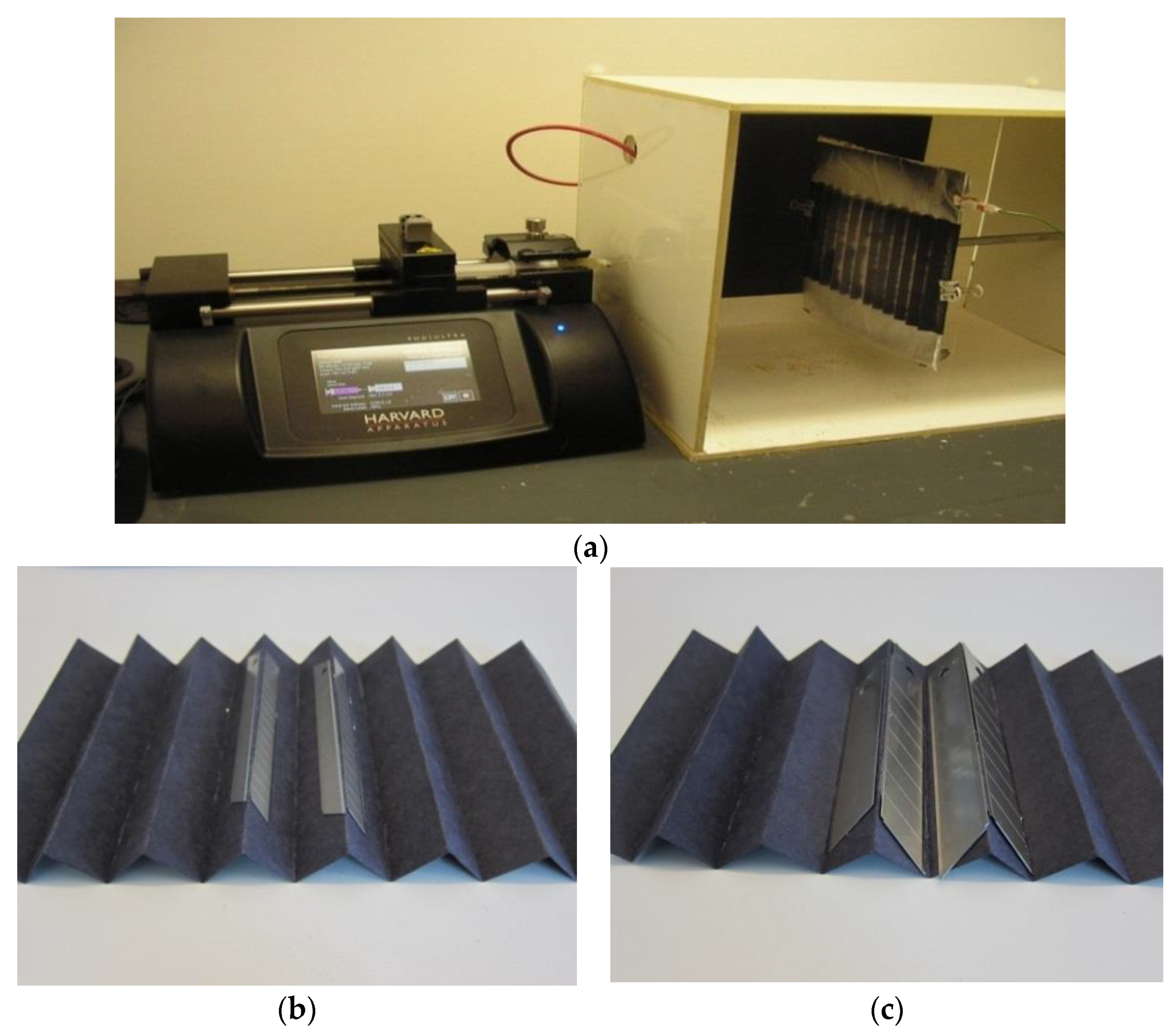
A conductor plate (grounded) with dimensions of 20 × 20 cm was used as the support for a V-shaped (pleated) cardboard substrate on which electrospun nanofibers were collected. The cardboard substrate was non-conductive and the conductor plate was placed close behind the cardboard substrate. A positively charged wire was connected to the spinneret (syringe needle) to control the electrical field, so that nanofibers were spun directly onto the V-shaped cardboard substrate. A voltage of 25 kV was applied to the needle. The distance between the needle and the conductor plate was 15 or 20 cm. A PHD/Ultra™ syringe pump (Harvard Apparatus, Holliston, MA, USA) was used to provide the polymer solution at a constant feed rate of 0.03 mL/h during electrospinning for 1 h. The other possibility would be to use a +/− charged conductor plate with a V-shaped cardboard collector and grounded syringe needle.
2.3. Variations of Special Collectors
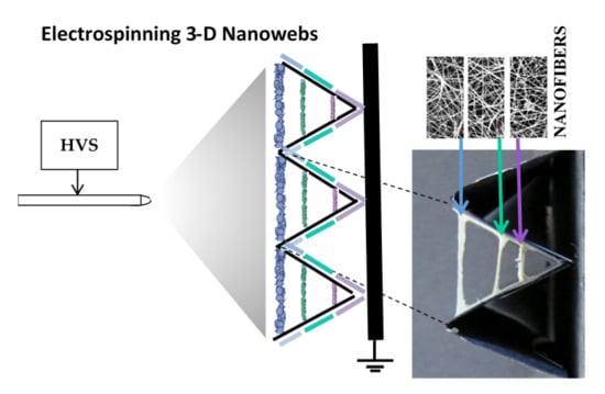
Figure 1 shows the general experimental set-up used to fabricate two dimensional (2-D) and 3-D nanofibrous structures. Electrospun nanofibers were deposited onto the V-shaped cardboard substrates at different locations, as shown in Figure 2 and described below for four variations: A, B, C, and D.
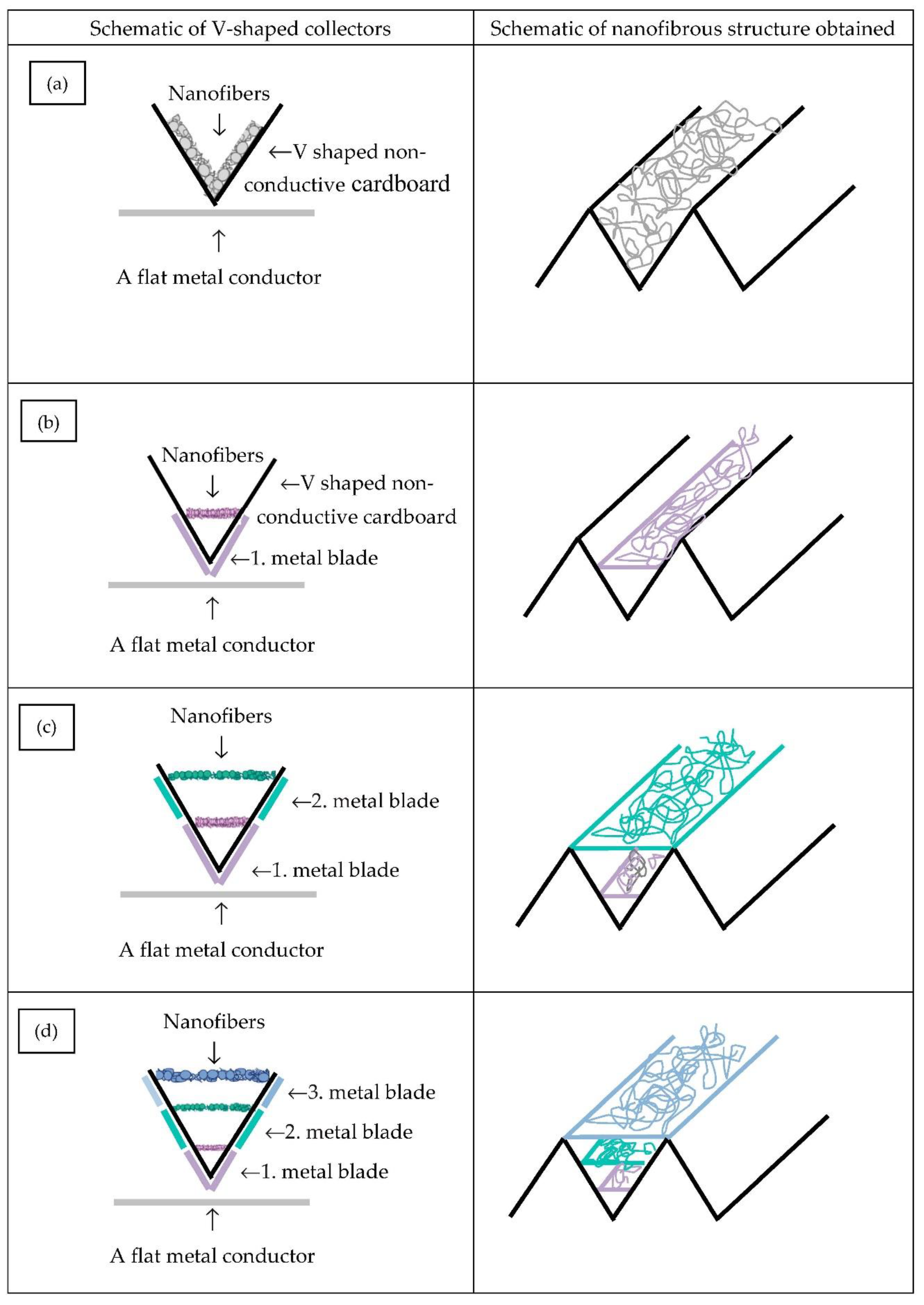
In the case of variation A, nanofibers were spun onto the V-shaped non-conductive cardboard substrate by keeping it in contact with the metal plate. Any other substrates made from textiles, non-wovens (spunbonded, melt-blown, needlepunched, etc.), filter papers, foams, and so forth may be used, depending on the porosity and pore size distribution of the substrate desired. The substrate, however, should not be conductive. This arrangement is shown schematically in Figure 2a on the left side. In this case (variation A) a flat metal conductor plate was kept behind the cardboard substrate as shown in Figure 1a.
In the case of variation B, nanofibers were spun onto a similar V-shaped cardboard substrate collector. However, in this case, two metal blades, as grounded conductors, were placed behind the cardboard (Figure 1b). The metal blades having a width of 5 or 10 mm and length of 100 mm ran the entire height of the V-shaped cardboard substrate. This is schematically shown in Figure 2b (left). Initially, the metal blades were placed at the corner (or base) of the ‘V’ grove and the fibers were electrospun (Figure 2b, right).
In the case of variation C, first, the nanofibers were electrospun in the same way as variation B, at the bottom of the ‘V’. Once that was completed, the metal blades were moved to the middle of the ‘V’, as seen in Figure 2c (left), and an additional layer of nanofibers was electrospun, as shown in Figure 2c (right).
The last variation, variation D, included all steps from variation C, and as the final step, the conductive metal blades were moved to the end (top) of the ‘V’ as shown in Figure 2d (left) and a third layer of nanofibers was electrospun, as shown in Figure 2d (right).
The surface morphologies of nanofibrous layers were characterized using a scanning electron microscope (SEM, LEO 1550 FE-SEM, Zeiss, Oberkochen, Germany) operating at an accelerating voltage of 15 kV. The specimens were adhered by a double-sided electrically conductive carbon tape onto the specimen stub and coated with a thin gold layer before observation in the SEM.
3. Results and Discussion
As proof of concept, two types of V-shaped cardboard substrates with different folding heights of 1 and 2 cm were utilized to confirm the feasibility of electrospinning different thicknesses, as shown in Figure 3. Moreover, tests were conducted at two different distances between the needle and the collector: 15 and 20 cm.
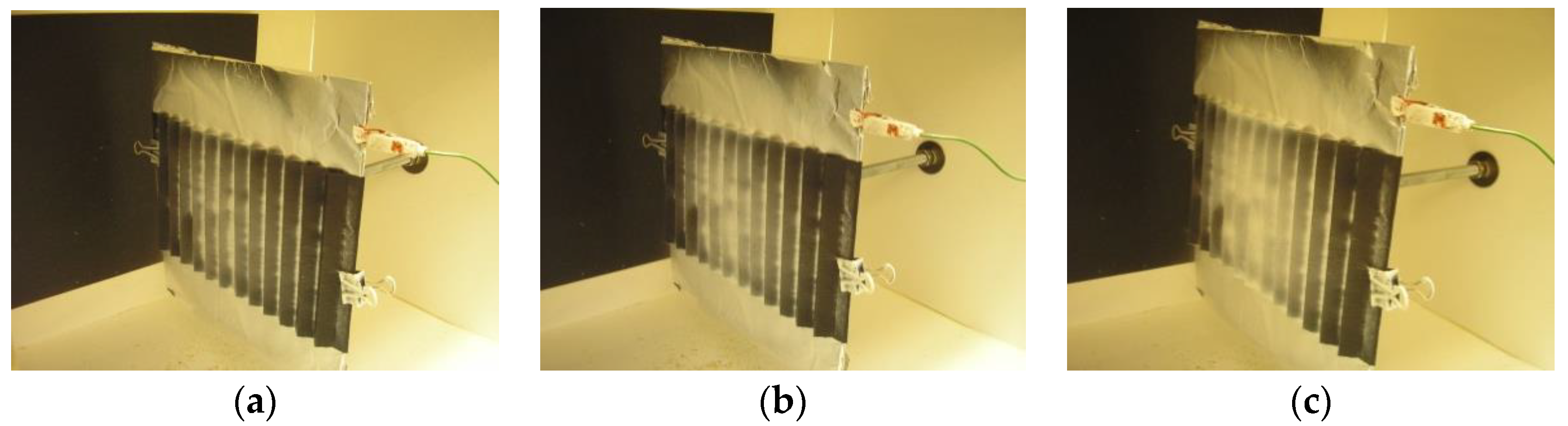
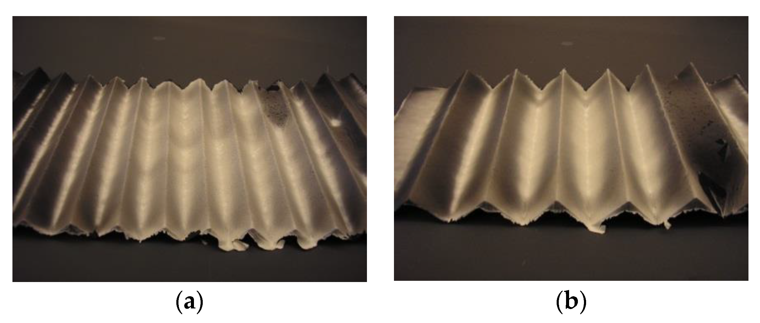
Photographs of the collector with collected nanofibers were taken every 15 min to assess the locations where the nanofibers were being deposited. Nanofibers covered almost all the surface of the V-shaped cardboard substrate when a metal conductor plate covering the entire area of the substrate was placed behind it, as in case A described earlier. Figure 4 shows the nanofiber build-up as a function of time for 1 × 1 cm folded cardboard substrate. Initially, the nanofibers were densely populated at the base of the V-shaped cardboard which was touching the metal conductor and with time, nanofibers filled the entire V-shaped space, as was expected. It was also noticed that the nanofiber density on the collector was highest at the base of the V-shape which was closest to the conductor and decreased away from the conductor. Similar behavior was observed for the 2 × 2 cm folded cardboard substrate as well. The sequential nanofiber growth on 2 × 2 cm folded cardboard substrate is shown in Figure 5. Figure 6 shows photographs of 1 × 1 cm and 2 × 2 cm folded substrates taken after 1 h of electrospinning.
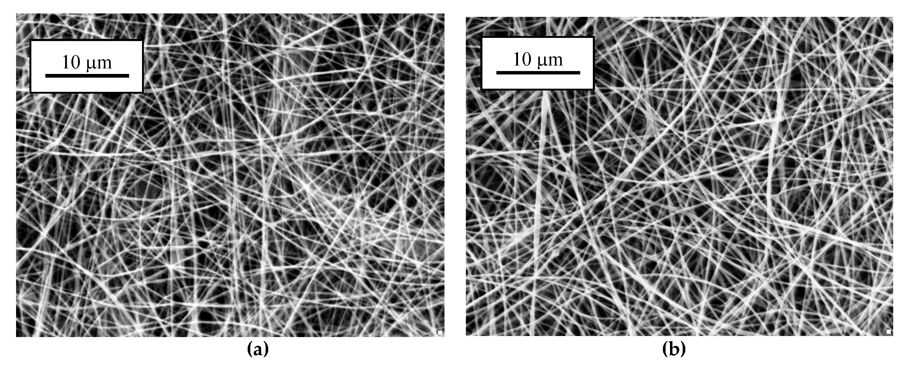
While in variation A, with a conducting plate placed behind the V-shaped cardboard substrate (i.e., no metal blades), electrospun nanofibers were laid on the surface where they formed a flat nanofibrous layer. To form a two-layered filter, the V-shaped cardboard substrate can be replaced with mini-pleated coarse filter media. This can ensure a high area of the filter media, as desired, to allow a lower pressure drop and higher loading capacity, thus increasing the useful filter life (before it gets clogged with particles), all of which can result in significant energy savings. However, as discussed, this set-up only laid nanofibers on the surface, forming a flat layer, and did not result in the desired nanofibrous 3-D structure, so other approaches (variations B, C, and D), shown in Figure 2, were tested subsequently. Typical SEM images of uniformly distributed nanofibers laid on the surface of substrate are shown in Figure 7. As can be seen, there are nanofibers with smaller diameters and broad diameter distribution when the needle to collector distance was maintained at 20 cm (193 ± 81 nm). In comparison, diameters of nanofibers created at a needle to collector distance of 15 cm are in average higher and the diameter distribution is narrower (230 ± 36 nm). The needle to collector distance certainly influences the diameters of the nanofibers, however, the difference in diameters was not significant in the present case. Numerous research groups have studied the effect of the distance between the needle tip and collector and concluded that nanofiber morphology could be easily affected by the distance. In general, defective and large-diameter nanofibers are formed when the collector-needle distance is kept small, whereas the diameter of the nanofiber is reduced as the distance is increased, as the elongation of the fluid jet occurs over a larger distance [1,7]. However, there are cases where a small or no effect on the morphology of the nanofiber was observed with a change in the distance between the metallic needle and collector [29,30]. The reason is that the effect of different needle-collector distances highly depends on the viscosity of the polymer solution, evaporation rate of the solvent, and the whipping or instability interval affected by environmental conditions such as temperature, humidity, and atmosphere composition [31].
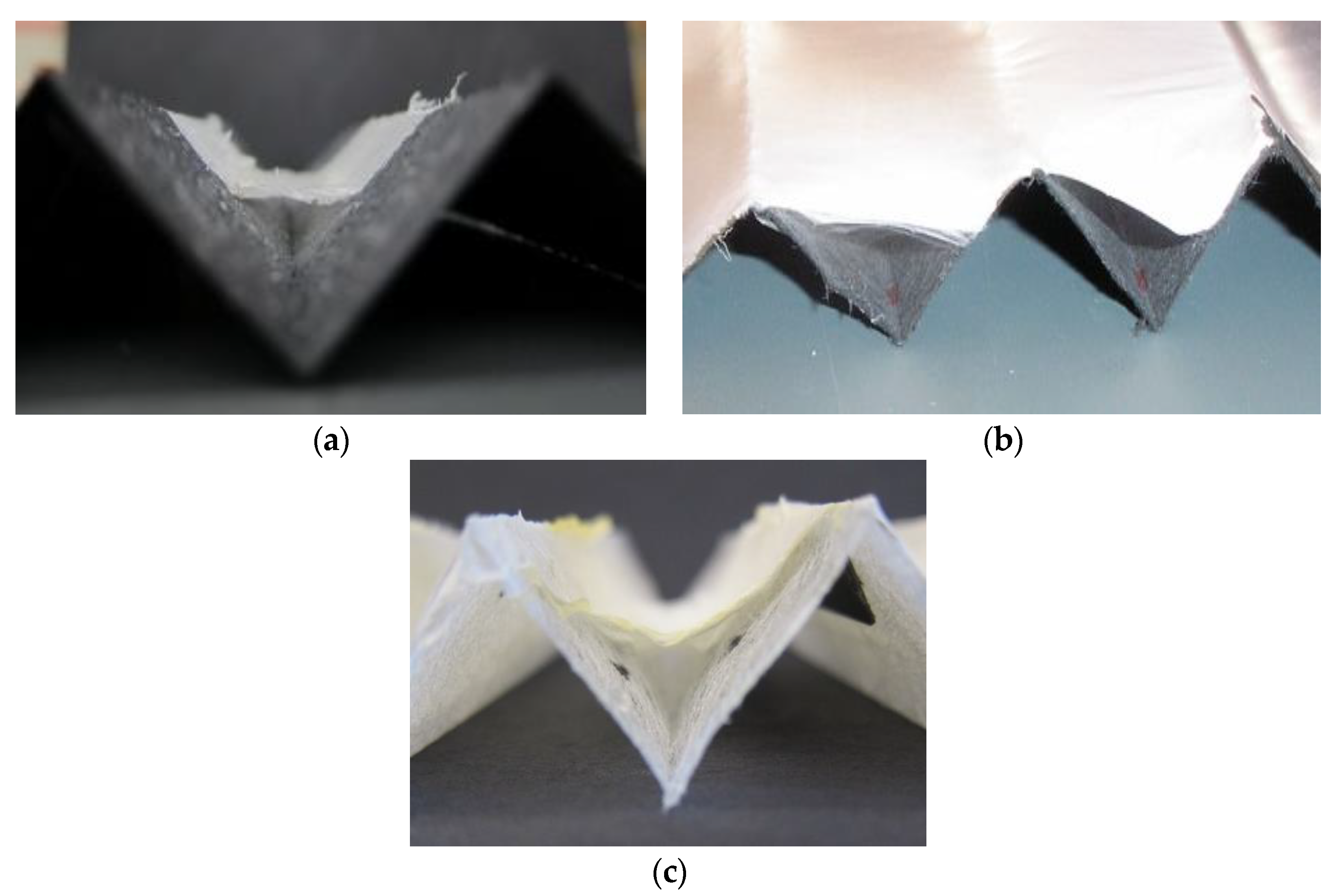
In variation B, shown earlier in the schematic in Figure 2b, metal blades were placed at the base of the ‘V’ shape. This attracts the nanofibers only towards those locations where the metal blades are in contact with the cardboard. This results in nanofibers forming a bridge between the sides of the V-shaped substrate, connecting only where the metal blades are present. Figure 8 shows different locations of the nanofiber layers formed on V-shaped cardboard (Figure 8a,b) and spun-bonded polypropylene substrates (Figure 8c). The needle to collector distance was maintained at 15 cm in all these experiments.
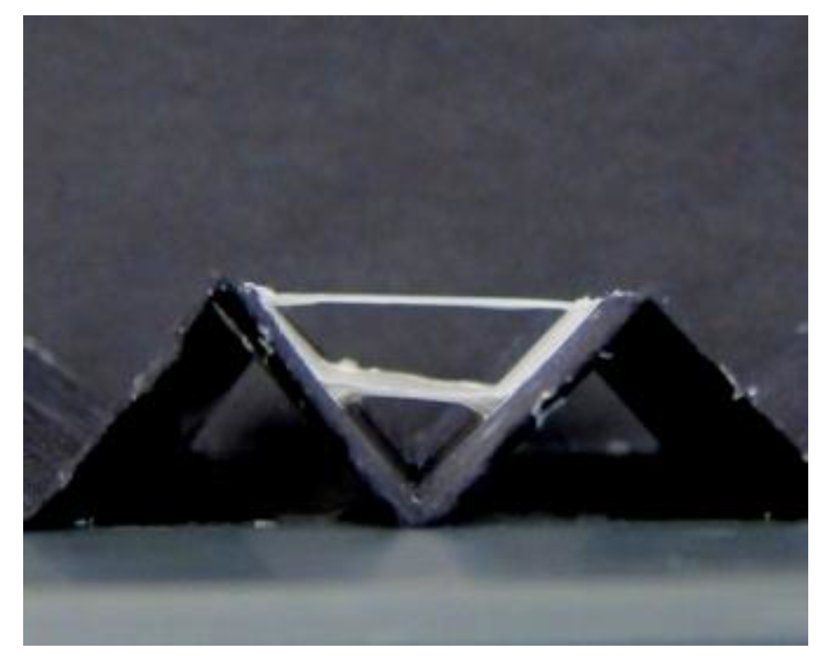
The potential of placing different nanofiber layers at desired locations (distances from the base of ‘V’ in the present case) can be clearly seen in Figure 8. This was explored further in variation C, where two bridges between the sides of the V were formed. This was easily achieved by first placing the two metal blades (5 mm) close to the middle of the V, and once that layer was formed, the metal blades were moved higher, from the base of the ‘V’, to form the second layer. Figure 9 shows two separate nanofiber bridges created between the two sides of the V-shaped cardboard using 5 mm wide metal blades.
When the distance between the needle and collector was increased from 15 to 20 cm, it was not possible to create more than one V-bridge because of the long distance between the collector and the needle. This suggests that the needle-to-collector distance can be a factor in controlling the nanofiber deposition. While this needs to be studied further, lower polymer viscosity might help in this case.
The ability of more nanofiber layers was tested further as proof-of-concept. In variation D, where three metal blade locations were used, separately, and nanofibers filled the space each time, making three separate individual layers, as was expected. The three distinct nanofiber layers are shown in Figure 10. This shows that it is possible to create many nanofiber layers simply by moving the grounded metal blades to different locations along the side walls of the V-shaped substrate. Further, the distance between the two layers can be easily controlled by placing the metal blades at desired locations, closer or further apart. Since the nanofibers get deposited only where the blades are, by moving the blades upwards while electrospinning, it should be possible to build the nanofibers continuously, rather than in separate layers. It is also intuitive from the proof-of-concept experiments discussed above that the nanofiber density (inter-nanofiber-spacing) through the space can be controlled by moving the blades at different speeds. For example, a slower blade motion can result in smaller inter-nanofiber-spacing, while a faster blade motion can give significantly higher inter-nanofiber-spacing. Since the metal blade dimensions (width and height) can be designed as small as needed, the thickness of the nanofiber layer can be controlled as well. The nanofiber layers with large spaces between them, along with the possibilities of building web structures with large thicknesses, can not only result in a low pressure drop for filters but can allow the filters to significantly increase the loading capacity and thus allow long time intervals before changing the filters and reduce significant amount of waste.
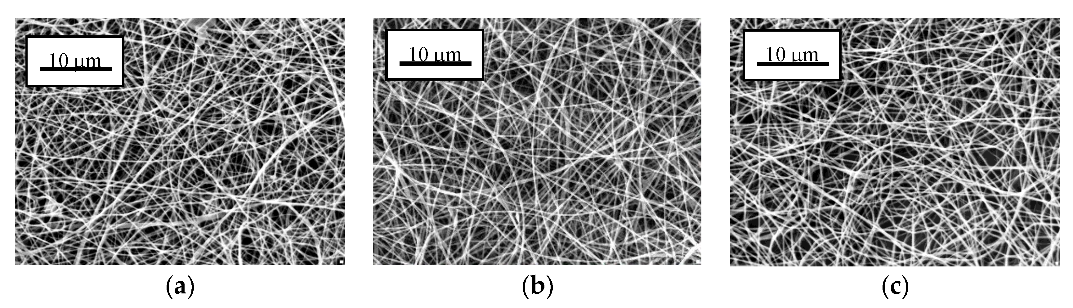
SEM images of all three bridges formed on the V-shaped substrate were taken for characterizing nanofiber diameters and distribution. Figure 11 shows typical SEM images of the three layers. All three layers looked similar with random fiber organization and the difference between their average diameters was found to be insignificant. Average nanofiber diameters and standard deviations for bottom, middle, and top bridges were 231 ± 33 nm, 233 ± 31 nm, and 236 ± 39 nm, respectively.
4. Future Possibilities and Development
4.1. Future Possibilities
It should be mentioned here that the experiments described above were done by moving the blades manually, in individual steps, to obtain variations B, C, and D. However, precise placement of the metal blades can be easily controlled by computer and precision motors, such that nanofiber bridges can be built with any desired spacing between them. Furthermore, by moving the metal blades in a continuous fashion, nanofiber formation can occur without the apparent separation of the layers. A slower movement of the metal plates will build denser nanofiber layers, whereas faster movement can build nanofibers with lower density (weight/unit space). In summary, automation in moving metal blades could easily achieve the desired nanofiber density, direction, and locations with high precision.
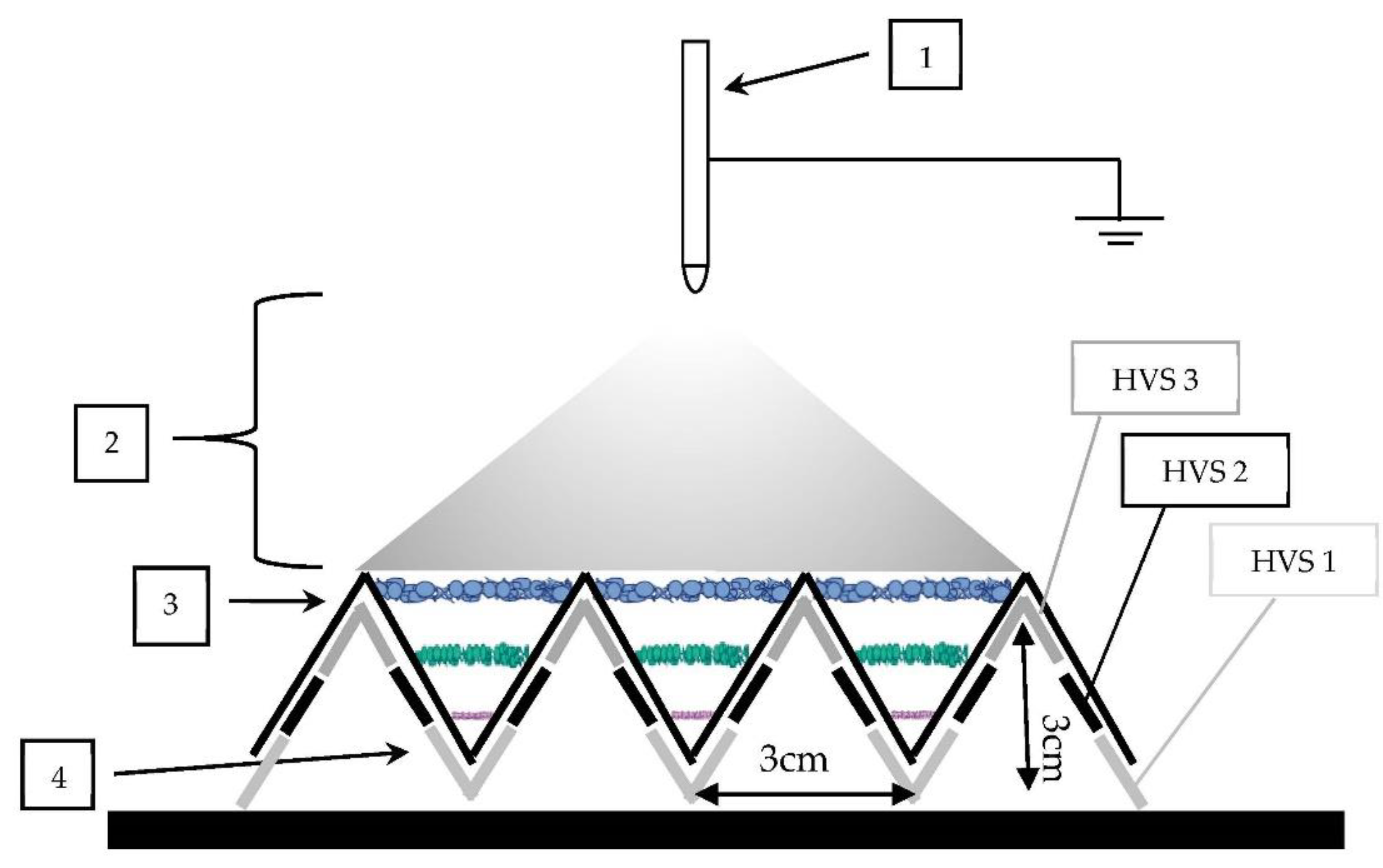
In another situation, many metal blades may be placed behind the substrate simultaneously, and by providing a sequential voltage connection to the blades on both sides of the V-shaped substrate slowly and simultaneously from the bottom to top of the ‘V’ with the help of three high voltage sources (HVSs), the nanofiber deposition location can be moved from the bottom to the top. Figure 12 shows the schematic of such an arrangement with three metal blades placed behind the V-shaped substrate. However, ideally, this may also be achieved using only 1 HVS and by using a switch that connects different metal blades.
In another refined variation, a single set of blades on either side of the V-shaped substrate can be moved upwards starting from the bottom position for a continuous buildup of nanofibrous 3-D structure. This version would require only one HVS and the blades’ movement can be computer controlled. If the blades were moved faster, lesser amount of nanofibers would get deposited (i.e., lower density) per unit area (or unit volume within the ‘V’ space) if the deposition rate (i.e., polymer flow rate) was kept unchanged. If the blades were moved slower, a higher density of nanofibers could be obtained through the same volume. The blade motion could also be varied along its upward path, as desired. Further, if the blades were to move in the opposite directions (or by moving only one blade while keeping the other at one location without moving), the nanofiber directions or angle they make with the walls of V-shaped substrate could also be changed. Thus, computer controlled blade movements could allow enormous possibilities for nanofiber laying within the substrate space.
In many cases, the fiber diameter may need to be varied through the thickness of the nanofiber web. Varying of fiber diameter may be achieved through individual layers or continuously through the thickness (layers) by changing the voltage used or by using different voltages if more than one HVSs are used. Other common variables such as the electrode to collector distance or concentration of polymer solutions could influence fiber diameter as well [32]. The nanofibrous 3-D web structure consisting of larger diameter of fibers in front and smaller diameter at the base could also be an ideal material for filtration. This may even eliminate the need for using the bilayer (substrate + nanofiber membrane) structure of the filters, as is the current practice [33,34].
The present method may also be modified where electrospinning is done using a drum as the electrode (instead of needle) but the collector system is maintained as described in the paper. A higher electrospinning speed because of the drum would make it easier to scale up this method to a commercial level to produce 3-D sheets.
4.2. Possible Applications of Nanofibrous 3-D Structures
The filter quality factor is a useful standard for comparing different types of filters and depends on many factors that include a filter’s packing density, the fiber diameter, and others [35]. Quality factors of nanofibrous filters and multi-layer fibrous filters have been examined by a few researchers [33,34,35,36,37]. For example, Podgorski et al. [34] investigated the filtration performances of some bilayer structures consisting of a microfibrous support and a nanofibrous facial collection layer. The nanofibrous layers were fabricated by the meltblown method. They found that the quality factors of the micro/nanofiber filters were significantly higher than conventional HEPA filters for 300 nm particles. They also studied the effect of adding more nanofiber mats to the bilayer structure. Results showed that the multi-nano/single-micro structure was beneficial and improved the filter quality factor significantly. Specifically, for 300 nm particles, the filter quality factor rose from 0.004 Pa−1 for one micro/nanofiber filter to 0.006 Pa−1 for an additional layer of the same nanofiber mat [34].
Zhang et al. [25] also found out that the filtration performance of nanofiber filters was significantly improved by using multiple thin layers of nanofiber mats. Stacking multiple thin layers of nanofiber mats benefited from the compensation of the inferior parts in each nanofiber mat and kept a high filter quality. The sandwiched multilayer nanofibrous media resulted in a quality factor better than the HEPA filter and military standard tested under the exact same conditions. The present study has shown a novel way of adding nanofiber layers separately or in a continuous form. Either way, the quality factor of the filters can be enhanced significantly.
Nanofibrous 3-D structures would also be ideal for tissue scaffolding, where different fiber densities and fiber diameters in different layers would mimic the tissue structures. Ki et al. [38] have discussed various 2-D and 3-D scaffolds whose cell adhesion and proliferation abilities were assessed by cultivating mouse fibroblasts. While the 2-D nanofiber mat exhibited excellent cell adhesion and proliferation abilities, significant cell migration was not possible because the spaces were too small. Authors showed that mouse fibroblast cells adhered and proliferated within 3-D nanofiber foam, having large amount of space, far better and with ease [38]. A similar porous structure can be easily built using the new 3-D method developed in this study.
5. Conclusions
This paper presents a new and facile method of electrospinning for creating nanofibrous 3-D structures and provides a proof-of-concept for the method. The new method allows electrospinning nanofibers to form 3-D web-like structures of desired thicknesses, where the fiber spacing, density (i.e., fiber volume/unit volume), as well as shape of the structure may be controlled. Additionally, it should be possible to vary the fiber diameters through the thickness of the 3-D web structure by controlling the variables such as the polymer solution (e.g., concentration, solvent evaporation), melt viscosity (e.g., temperature, molecular weight of polymer), or flow rate while building the nanofibrous 3-D structure.
The new technique presented here can also be used in a myriad of applications other than air filtration where nanofibrous 3-D structures would be highly beneficial. These include tissue scaffolding for building artificial skin and other organs, deep wound healing, ultra-light-weight insulation, hydrogel preparation, and many others.
While many variations are possible with this novel method, this paper discusses a few cases, as proof-of-concept, that illustrate how multilayered nanofibrous 3-D structures can be made, particularly for application in air filtration. The computerized automation of the method should make it possible to build a myriad of structures suitable for a variety of applications.
Author Contributions
D.L. planned and did all experiments as well as prepared the first draft of manuscript. A.N.N. did planning, supervision, and worked on the manuscript. All authors have read and agreed to the published version of the manuscript.
Funding
This research received no external funding.
Conflicts of Interest
The authors declare no conflicts of interest.
References
- Doshi, J.; Reneker, D.H. Electrospinning process and applications of electrospun fibers. J. Electrost. 1995, 35, 151–160. [Google Scholar] [CrossRef]
- Kirichenko, V.; Filatov, Y.; Budyka, A. Electrospinning of Micro- and Nanofibers: Fundamentals in Separation and Filtration Processes; Begell House Publishers Inc.: Danbury, CT, USA, 2007; pp. 1–488. [Google Scholar]
- Park, J.-S. Electrospinning and its applications. Adv. Nat. Sci. Nanosci. 2010, 1, 1–5. [Google Scholar] [CrossRef] [Green Version]
- Ramakrishna, S.; Fujihara, K.; Teo, W.; Lim, T.; Ma, Z. An Introduction to Electrospinning and Nanofibers; World Scientific: Singapore, 2005; pp. 1–396. [Google Scholar]
- Bognitzki, M.; Czado, W.; Frese, T.; Schaper, A.; Hellwig, M.; Steinhard, M.; Greiner, A.; Wendorff, J.H. Nanostructured fibers via electrospinning. Adv. Mater. 2001, 13, 70–72. [Google Scholar] [CrossRef]
- Hohman, M.M.; Shin, M.; Rutledge, G.C.; Brenner, M.P. Electrospinning and electrically forced jets. II. Applications. Phys. Fluids 2001, 13, 2221. [Google Scholar] [CrossRef] [Green Version]
- Thompson, C.J.; Chase, G.G.; Yarin, A.L.; Reneker, D.H. Effects of parameters on nanofiber diameter determined from electrospinning model. Polymer 2007, 48, 6913–6922. [Google Scholar] [CrossRef]
- Reneker, D.H.; Yarin, A.L. Electrospinning jets and polymer nanofibers. Polymer 2008, 49, 2387–2425. [Google Scholar] [CrossRef] [Green Version]
- Jun, I.; Han, H.S.; Edwards, J.R.; Jeon, H. Electrospun Fibrous Scaffolds for Tissue Engineering: Viewpoints on Architecture and Fabrication. Int. J. Mol. Sci. 2018, 19, 745. [Google Scholar] [CrossRef] [Green Version]
- Lubasova, D.; Netravali, A.N.; Parker, J.; Ingel, B. Bacterial Filtration Efficiency of Green Soy Protein based Nanofiber Air Filter. J. Nanosci. Nanotechnol. 2014, 14, 4891–4898. [Google Scholar] [CrossRef]
- Lubasova, D.; Netravali, A.N.; Mullerova, J. Water Resistant Plant Protein-based Nanofiber Membranes. J. Appl. Polym. Sci. 2015, 132, 41852–41859. [Google Scholar] [CrossRef]
- Lubasova, D.; Niu, H.; Zhao, X.; Lin, T. Hydrogel properties of electrospun polyvinylpyrrolidone and polyvinylpyrrolidone/poly(acrylic acid) blend nanofibers. RSC Adv. 2015, 5, 54481–54487. [Google Scholar] [CrossRef]
- Tian, X.; Xin, B.; Lu, Z.; Gao, W.; Zhang, F. Electrospun sandwich polysulfonamide/ Polyacrylo-nitrile/polysulfonamide composite nanofibrous membranes for lithium-ion batteries. RSC Adv. 2019, 9, 11220–11229. [Google Scholar] [CrossRef] [Green Version]
- Wright, L.D.; Young, R.T.; Andric, T.; Freeman, J.W. Fabrication and mechanical characterization of 3D electrospun scaffolds for tissue engineering. Biomed. Mater. 2010, 5, 055006. [Google Scholar] [CrossRef] [PubMed]
- Sun, B.; Long, Y.Z.; Yu, F.; Li, M.M.; Zhang, H.D.; Li, W.J.; Xu, T.X. Self-assembly of a three-dimensional fibrous polymer sponge by electrospinning. Nanoscale 2012, 4, 2134–2137. [Google Scholar] [CrossRef] [PubMed]
- Joseph, J.; Nair, S.V.; Menon, D. Integrating Substrateless Electrospinning with Textile Technology for Creating Biodegradable Three-Dimensional Structures. Nano. Lett. 2015, 15, 5420–5426. [Google Scholar] [CrossRef]
- Leong, W.S.; Wu, S.C.; Ng, K.W.; Tan, L.P. Electrospun 3D multi-scale fibrous scaffold for enhanced human dermal fibroblasts infiltration. Int. J. Bioprinting 2016, 2, 81–92. [Google Scholar] [CrossRef]
- Liu, Y.; Liu, R.; Wang, X.; Jiang, J.; Li, W.; Liu, J.; Guo, S.; Zheng, G. Electrospun Three-Dimensional Nanofibrous Structure via Probe Arrays Inducing. Micromachines 2018, 9, 427. [Google Scholar] [CrossRef] [Green Version]
- Song, J.; Zhu, G.; Gao, H.; Li, N.; Shi, X.; Wang, Y. Origami meets electrospinning: A new strategy for 3D nanofiber scaffolds. Bio-Des. Manuf. 2018, 1, 254–264. [Google Scholar] [CrossRef]
- Ma, P.X. Tissue engineering. In Encyclopedia of Polymer Science and Technology, 3rd ed.; Kroschwitz, J.I., Ed.; John Wiley & Sons, Inc.: Hoboken, NJ, USA, 2005; pp. 261–291. [Google Scholar]
- Loh, Q.L.; Choong, C. Three-dimensional scaffolds for tissue engineering applications: Role of porosity and pore size. Tissue Eng. Part B Rev. 2013, 19, 485–502. [Google Scholar] [CrossRef] [Green Version]
- Balamurugan, R.; Sundarrajan, S.; Ramakrishna, S. Recent Trends in Nanofibrous Membranes and Their Suitability for Air and Water Filtrations. Membranes 2011, 1, 232–248. [Google Scholar] [CrossRef] [Green Version]
- Barhate, R.S.; Loong, C.K.; Ramakrishna, S. Preparation and characterization of nanofibrous filtering media. J. Membr. Sci. 2016, 283, 209–218. [Google Scholar] [CrossRef]
- Tang, Z.; Qiu, C.; McCutcheon, J.R.; Yoon, K.; Ma, H.; Fang, D.; Lee, E.; Kopp, C.; Hsiao, B.S.; Chu, B. Design and fabrication of electrospun polyethersulfone nanofibrous scaffold for high-flux nanofiltration membranes. J. Polym. Sci. Part B Pol. Phys. 2009, 47, 2288–2300. [Google Scholar] [CrossRef]
- Zhang, Q.; Welch, J.; Park, H.; Wu, C.; Sigmund, W.; Marijnissen, J.C.M. Improvement in nanofiber filtration by multiple thin layers of nanofiber mats. J. Aerosol Sci. 2010, 41, 230–236. [Google Scholar] [CrossRef]
- Barhate, R.S.; Ramakrishna, S. Nanofibrous filtering media: Filtration problems and solutions from tiny materials. J. Membr. Sci. 2007, 296, 1–8. [Google Scholar] [CrossRef]
- Leung, W.W.; Hung, C.; Yuen, P. Effect of face velocity, nanofiber packing density and thickness on filtration performance of filters with nanofibers coated on a substrate. Sep. Purif. Ttechnol. 2010, 71, 30–37. [Google Scholar] [CrossRef]
- Kosmider, K.; Scott, J. Polymeric nanofibres exhibit an enhanced air filtration performance. Filt. Sep. 2002, 39, 20–22. [Google Scholar] [CrossRef]
- Zhang, C.; Yuan, X.; Wu, L.; Han, Y. Study on morphology of electrospun poly(vinyl alcohol) mats. Eur. Polym. J. 2005, 41, 423–432. [Google Scholar] [CrossRef]
- Megelski, S.; Stephens, J.S.; Bruce Chase, D.; Rabolt, J.F. Micro- and nanostructured surface morphology on electrospun polymer fibers. Macromolecules 2002, 35, 8456–8466. [Google Scholar] [CrossRef]
- Haider, A.; Haider, S.; Kang, I.-K. A comprehensive review summarizing the effect of electrospinning parameters and potential applications of nanofibers in biomedical and biotechnology. Arab. J. Chem. 2018, 11, 1165–1188. [Google Scholar] [CrossRef]
- Korycka, P.; Mirek, A.; Kramek-Romanowska, K.; Grzeczkowicz, M.; Lewińska, D. Effect of electrospinning process variables on the size of polymer fibers and bead-on-string structures established with a 23 factorial design. Beilstein J. Nanotechnol. 2018, 9, 2466–2478. [Google Scholar] [CrossRef] [Green Version]
- Wang, J.; Kim, S.C.; Pui, D.Y.H. Investigation of the figure of merit for filters with a single nanofiber layer on a substrate. J. Aerosol Sci. 2008, 39, 323–334. [Google Scholar] [CrossRef]
- Podgorski, A.; Balazy, A.; Gradon, L. Application of nanofibers to improve the filtration efficiency of the most penetrating aerosol particles in fibrous filters. Chem. Eng. Sci. 2006, 61, 6804–6815. [Google Scholar] [CrossRef]
- Hinds, W.C. Aerosol Technology: Properties, Behavior, and Measurement of Airborne Particles; John Wiley & Sons, Inc.: New York, NY, USA, 1999; pp. 183–205. [Google Scholar]
- Givehchi, R.; Li, Q.; Tan, Z. Quality factors of PVA nanofibrous filters for airborne particles in the size range of 10–125 nm. Fuel 2016, 181, 1273–1280. [Google Scholar] [CrossRef]
- Yun, K.M.; Hogan, C.J., Jr.; Matsubayashi, Y.; Kawabe, M.; Iskandar, F.; Okuyama, K. Nanoparticle filtration by electrospun polymer fibers. Chem. Eng. Sci. 2007, 62, 4751–4759. [Google Scholar] [CrossRef]
- Ki, C.S.; Kim, J.W.; Hyun, J.H.; Lee, K.H.; Hattori, M.; Rah, D.K.; Park, Y.H. Electrospun three-dimensional silk fibroin nanofibrous scaffold. J. Appl. Polym. Sci. 2007, 106, 3922–3928. [Google Scholar] [CrossRef]
Figure 1.
(a): A photograph of the experimental set-up used for electrospinning nanofibrous 2-D and three-dimensional (3-D) structures, V-shaped cardboard collectors showing the placings of the grounded metal blades: 1 (b) of 5 mm width, (c) of 10 mm width.
Figure 1.
(a): A photograph of the experimental set-up used for electrospinning nanofibrous 2-D and three-dimensional (3-D) structures, V-shaped cardboard collectors showing the placings of the grounded metal blades: 1 (b) of 5 mm width, (c) of 10 mm width.

Figure 2.
Schematic of 3-D nanofibrous layer producing setups for variations A–D (a–d).

Figure 3.
A schematic of the 1 × 1 cm (left) and 2 × 2 cm (right) V-shaped cardboard substrates.

Figure 4.
Photographs of 1 × 1 cm V-shaped collector showing collected nanofibers after: (a) 15 min, (b) 30 min, and (c) 1 h of electrospinning.
Figure 4.
Photographs of 1 × 1 cm V-shaped collector showing collected nanofibers after: (a) 15 min, (b) 30 min, and (c) 1 h of electrospinning.

Figure 5.
Photographs of 2 × 2 cm V-shaped folded collectors showing collected nanofibers after: (a) 15 min, (b) 30 min, and (c) 1 h of electrospinning.
Figure 5.
Photographs of 2 × 2 cm V-shaped folded collectors showing collected nanofibers after: (a) 15 min, (b) 30 min, and (c) 1 h of electrospinning.

Figure 6.
Photographs showing details of collected nanofibers: (a) 1 × 1 cm V-shaped cardboard substrate and (b) 2 × 2 cm V-shaped cardboard substrate after 1 h of electrospinning.
Figure 6.
Photographs showing details of collected nanofibers: (a) 1 × 1 cm V-shaped cardboard substrate and (b) 2 × 2 cm V-shaped cardboard substrate after 1 h of electrospinning.

Figure 7.
SEM images of SPC/PEO nanofibers collected on the V-shaped cardboard substrate with a different distance between the needle and collector: (a) 20 cm and (b) 15 cm.
Figure 7.
SEM images of SPC/PEO nanofibers collected on the V-shaped cardboard substrate with a different distance between the needle and collector: (a) 20 cm and (b) 15 cm.

Figure 8.
Photographic images showing nanofiber layers on cardboard and spun-bonded polypropylene (PP) substrates: (a) in the middle of the ‘V’ (location of 5 mm wide metal blades), (b) in the middle of the ‘V’ (location of 10 mm wide metal blades), and (c) nanofibers laid on the V-shaped spun-bonded PP substrate.

Figure 9.
Photographic image showing two nanofiber bridges between the two sides of the V-shaped substrate (variation C).
Figure 9.
Photographic image showing two nanofiber bridges between the two sides of the V-shaped substrate (variation C).

Figure 10.
Photographic images showing three nanofiber bridges between the two walls of V-shaped substrate (variation D): (a) directly after electrospinning and (b) after removing nanofibers in front manually using a cosmetic stick.
Figure 10.
Photographic images showing three nanofiber bridges between the two walls of V-shaped substrate (variation D): (a) directly after electrospinning and (b) after removing nanofibers in front manually using a cosmetic stick.

Figure 11.
Typical SEM images showing three nanofiber bridges between the two walls of V-shaped substrate (variation D): (a) bottom bridge, (b) middle bridge, and (c) top bridge.
Figure 11.
Typical SEM images showing three nanofiber bridges between the two walls of V-shaped substrate (variation D): (a) bottom bridge, (b) middle bridge, and (c) top bridge.

Figure 12.
The schematic set-up for the production of three nanofiber layers by sequential voltage connection of blades deposited onto V-shaped substrate: 1—needle supplying polymer solution, 2—nanofibers being formed by the elongation of an electrified fluid jet, 3—V-shaped substrate, 4—three sets of metal blades.

© 2020 by the authors. Licensee MDPI, Basel, Switzerland. This article is an open access article distributed under the terms and conditions of the Creative Commons Attribution (CC BY) license (http://creativecommons.org/licenses/by/4.0/).
Share and Cite
MDPI and ACS Style
Lubasova, D.; Netravali, A.N. A Novel Method for Electrospinning Nanofibrous 3-D Structures. Fibers 2020, 8, 27. https://0-doi-org.brum.beds.ac.uk/10.3390/fib8050027
AMA Style
Lubasova D, Netravali AN. A Novel Method for Electrospinning Nanofibrous 3-D Structures. Fibers. 2020; 8(5):27. https://0-doi-org.brum.beds.ac.uk/10.3390/fib8050027
Chicago/Turabian StyleLubasova, Daniela, and Anil N. Netravali. 2020. "A Novel Method for Electrospinning Nanofibrous 3-D Structures" Fibers 8, no. 5: 27. https://0-doi-org.brum.beds.ac.uk/10.3390/fib8050027
Note that from the first issue of 2016, this journal uses article numbers instead of page numbers. See further details here.