
Numerical and Experimental Analysis of Fire Resistance for Steel Structures of Ships and Offshore Platforms


Peter the Great St. Petersburg Polytechnic University, 195251 St. Petersburg, Russia
*
Author to whom correspondence should be addressed.
Fire 2022, 5(1), 9; https://0-doi-org.brum.beds.ac.uk/10.3390/fire5010009
Submission received: 19 December 2021
/
Revised: 12 January 2022
/
Accepted: 14 January 2022
/
Published: 16 January 2022
(This article belongs to the Special Issue Performance-Based Design in Structural Fire Engineering)
Abstract
:The requirements for the fire resistance of steel structures of oil and gas facilities for transportation and production of hydrocarbons are considered (structures of tankers and offshore platforms). It is found that the requirements for the values of fire resistance of structures under hydrocarbon rather than standard fire conditions are given only for offshore stationary platforms. Experimental studies on the loss of integrity (E) and thermal insulating capacity (I) of steel bulkheads and deck with mineral wool under standard and hydrocarbon fire regimes are presented. Simulation of structure heating was performed, which showed a good correlation with the experimental results (convective heat transfer coefficients for bulkheads of class H: 50 W/m2·K; for bulkheads of class A: 25 W/m2·K). The consumption of mineral slabs and endothermic mat for the H-0 bulkhead is predicted. It is calculated that under a standard fire regime, mineral wool with a density of 80–100 kg/m2 and a thickness of 40 to 85 mm should be used; under a hydrocarbon fire regime, mineral wool with a density above 100 kg/m2 and a thickness of 60–150 mm is required. It is shown that to protect the structures of decks and bulkheads in a hydrocarbon fire regime, it is necessary to use 30–40% more thermal insulation and apply the highest density of fire-retardant material compared to the standard fire regime. Parameters of thermal conductivity and heat capacity of the applied flame retardant in the temperature range from 0 to 1000 °C were clarified.
1. Introduction
Building structures of reservoirs, equipment and structures in an accident, accompanied by fire and explosion, are subjected to high-temperature impact due to the large number and type of fire load [1,2]. In Europe and the USA, combustion of hydrocarbons (oil, oil products) and the development of fire are considered on the hydrocarbon fire curve, at which, in the first minutes of the fire, the temperature reaches 1000 °C and higher [3,4]. In the design of structures of the oil and gas complex (O&G) in Russia, the condition of fire development on the standard (“cellulose”) curve according to ISO 834 [5] is used.
Tankers are in second place in the total transportation volume of oil and petroleum products (after oil pipes). The highest risk of formation of explosive mixtures inside the tanker occurs during tanker unloading. When the liquid level drops, the air is exhausted into the tank and mixed with petroleum product vapors [6]. As petroleum vapors are heavier than air, they can spread through tanker rooms and ignite over large areas. Ships and offshore platforms consist of decks, compartments and interior spaces that contain several systems, subsystems and components necessary for operation. Explosion, fire or flooding of compartments can damage equipment and cause a critical risk to operations [7,8,9]. In [10], an empirical method was used to calculate the compressive strength limit in the center of the deck, according to the results of which, the maximum compressive stress on the deck was 175.53 MPa; the deflection value in the middle part of the deck did not exceed the acceptable value. In [11], the design of a working barge with a displacement of 5000 tons was demonstrated. Mechanical calculation showed sufficient strength under normal loading conditions and even in an emergency. In [12], the steel deck’s behavior under different hydrocarbon ignition scenarios using ANSYS software was studied. Numerical studies of steel decks under the combined action of mechanical load and hydrocarbon fire regime are given, showing an increased deformation of the deck and reduced deck fire resistance under the considered fire scenarios. In [13,14], a fire was simulated using FDS structures of offshore platforms, and the fire risk was calculated. The authors investigated the behavior of steel structures of the upper part of an offshore platform under fire and hydrocarbon explosion and under wind load; the calculation was performed in ABAQUS software [15]. The thermophysical characteristics of the intumescent paints used as fire protection of steel structures were obtained in [16].
Steel structures in the ship’s hull and structures of cargo tanks, decks and bulkheads that separate industrial rooms are designed with certain fire-resistance classes, depending on the parameters of the fire-resistance limits and temperature exposure modes: A, B, C and H (standard regime—A, B, C classes, and hydrocarbon—H class). The same fire-resistance classes are established for oil platforms [17]. In [18], a simulation of the thermal impact on the steel structure A-60 was presented, from the results of which the temperature distribution was calculated. The analysis results allow consideration of the design and safety planning aspects of an offshore living compartment.
According to SOLAS Regulation II-2/17 [19], decks and bulkheads shall be made of non-combustible materials and are classified as follows:
- (1)
- “B” class divisions: B-15 and B-0;
- (2)
- “A” class divisions: A-60, A-30, A-15 and A-0;
- (3)
- “C” class divisions: divisions constructed of approved non-combustible materials.
Another classification of decks and bulkheads is also regulated in [17]:
- (4)
- “H” class divisions: H-120, H-60 and H-0.
Figure 1 shows the location of the H-120 deck and A-60 and B-15 class bulkheads on the tanker.
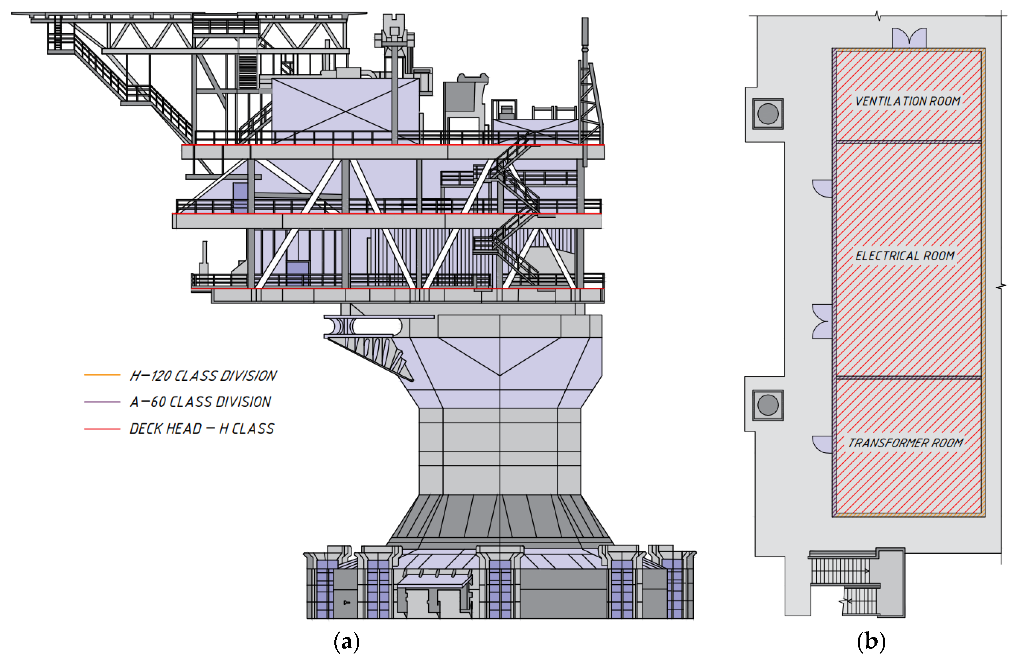
Figure 2 shows the location of the H-120 deck and A-60 and H-120 class bulkheads on an offshore platform.
Fire-resistance tests of structures for ships and offshore structures are conducted following the requirements stated in SOLAS Regulation II-2/17 [19], International Maritime Organization (IMO) resolutions and guidelines of IMO member countries, for example, American Bureau of Shipping (ABS) [20] and Russian Maritime Register of Shipping (RS) [21]. Tests for fire resistance are carried out using both methods for determining the fire resistance of structures by the standard temperature regime (curves for A, B, C), which is similar to that established in ISO 834 [5], and by the hydrocarbon fire regime (curve H) for island structures and floating platforms. In the USA, the standard UL 1709 [22] is applied, which differs from the European EN 1363-2:1999 [23] in the development of a fire in the first minutes [24,25].
According to ISO 834-75 [5], IMO Res. A.754 [26] and the Russian State Standard GOST 30247.1 “Elements of building constructions. Fire-resistance test methods. Loadbearing and separating constructions” [27] harmonized with ISO 834 [5], the following limit conditions are distinguished for fire-resistance limits of enclosure structures, which include bulkheads and decks of tankers and platforms:
- —
- Loss of integrity resulting from the formation of through cracks or openings in the structures through which combustion products or flame (E) penetrate to the unheated surface;
- —
- Loss of thermal insulating capability (I) due to an average temperature rise of more than 140 °C at the unheated surface of the structure or at any point on that surface of more than 180 °C compared with the temperature of the structure before the test or more than 220 °C regardless of the temperature of the structure before the test (additional limit conditions of structures and the criteria of their occurrence are established, if necessary, in the standards for tests of particular structures). It should be noted that the same requirements for the quantitative values of the thermal insulating capacity (I) and qualitative features of the loss of integrity (E) are established for the enclosing structures.
Minimum requirements for fire resistance of bulkheads and decks are established in [17,20,28], for example, for bulkheads in [17] (Table 1).
Insulation materials should generally be non-combustible or show low combustion spreading to ensure structural fire resistance of ships and platforms [29,30,31]. Mineral wool of various densities is widely used in passive fire protection (PFP) [32,33] and less commonly used in epoxy-based fire-retardant intumescent paints [4]. Fire protection is applied (mounted) between thin metal walls as bulkhead panels on vertical structural elements of offshore structures. Studies related to the design, calculation and modeling of decks and bulkheads include either only calculations of the compressive strength and deflection values at the center of the structure [10,11] or only modeling of hydrocarbon fire and explosion scenarios [12,13,14,15,18]. In [34], two experiments of bulkheads under standard and hydrocarbon fire regimes are given, with their subsequent modeling confirming the correlation of the obtained temperatures, from which the conclusion about the possibility of prediction and justification of the fire-resistance limits by simulation is made.
The purpose of this article is to simulate experimental data for determining the fire-resistance limit of bulkheads of different classes and deck for an offshore platform to solve the following problems: calculation of the parameters of thermal insulation of bulkheads and deck; prediction of the fire-resistance limits of the structure on the example of the H-0 bulkhead depending on the thickness of mineral wool and its density for the H-0 bulkhead under a hydrocarbon fire regime with the variant to replace the used fire protection to endothermic mat based on ceramics and basalt fibers; calculation of the H-0 bulkhead on a deflection in the center of the considered structure under thermal load; and clarification of calculated coefficients of thermal conductivity and heat capacity for mineral wool in the temperature range from 0 to 1000 °C.
2. Materials and Methods
Experimental samples of H-class bulkheads and deck were tested to determine the time of reaching the limit state during fire exposure according to IMO FTP Code Part 3 IMO Res. A.754 (18) [26] under the condition of establishing a hydrocarbon temperature regime in the fire chamber of the furnace according to EN 1363-2: 1999 [23], characterized by dependence (1):
where T means the temperature inside the furnace in °C, corresponding to the relevant time t; T0 is the temperature in °C inside the furnace prior to the start of heat impact; t is the time in minutes from the start of the test.
Experimental samples of A-class bulkheads were tested to determine the time of reaching the limit state during fire exposure according to IMO FTP Code Part 3 IMO Res. A.754 (18) [26] under the condition of creating in the fire chamber of the furnace a standard temperature regime according to ISO 834 [5], characterized by dependence (2):
The furnace temperature was determined by means of twelve thermoelectric transducers with a switching head uniformly distributed at a distance of approximately 100 mm from the exposed side of the test sample according to IMO Res. A.754 (18) [26]. The temperature in the furnace during the fire tests was maintained according to the appropriate temperature regimes [23]. The temperature on the test samples was measured by cable thermoelectric chromel–alumel thermocouples. According to the test reports of the structure, each thermocouple is inserted through a steel pipe of standard weight, and the end of the pipe from which the welded junction protrudes is to be open. The thermocouple junction protrudes ½ in (12.7 mm) from the open end of the pipe.
The ambient temperature during the tests was averaged according to the test reports and assumed 20 °C.
The software package (SP) ELCUT [35] was used to analyze the temperature distribution over the cross-section of the considered structures.
2.1. Experiments on Bulkhead and Deck Structures
The fire resistance of H-class bulkheads (H-0, H-60, H-120), A-class bulkheads (A-15, A-60) and deck (H-120) with mineral wool materials was investigated.
Fire tests of the H-0, H-60 and H-120 bulkheads were carried out at the Danish Institute of Fire and Security Technology (DIFT). The bulkheads were installed in a reinforced concrete frame and welded on four sides to the restraint frame. The dimensions of the structural core were following IMO Resolution A.754 (18). The test samples were tested with the insulation and the stiffeners toward the furnace.
The H-0 bulkhead has the following external dimensions: height 2480 mm, width 2420 mm, thickness 64.5/129.5 mm. The bulkhead consisted of a standard structural steel core insulated with Rockwool insulation (Hedehusene, Denmark), attached to the bulkhead with ø3 mm pins and ø28 mm washers. The pins on the level were located in 3 lines and a line on each of the stiffeners. The vertical center distance between the pins on the level was 400 mm along all lines. The vertical center distance between the pins on the stiffeners was 300 mm along all lines. The steel sheet thickness of 4.5 mm with the pins on the stiffeners at a distance of 600 mm was insulated with two layers of 30 mm Rockwool HC Firebatt (Hedehusene, Denmark) mineral wool with a density of 150 kg/m³.
The H-60 bulkhead has the following external dimensions: height 2480 mm, width 2420 mm, thickness 75/115 mm. The steel sheet thickness of 5 mm with the pins on the stiffeners at a distance of 600 mm was insulated with two layers of mineral wool: 40 mm Rockwool HC Wired Matt (Hedehusene, Denmark) with a density of 150 kg/m3 and 30 mm Rockwool HC Firebatt with a density of 150 kg/m3. Installation of the insulation to the bulkhead is similar to the H-0 bulkhead.
The H-120 bulkhead has the following external dimensions: height 2480 mm, width 2420 mm, thickness 95/155 mm. The steel sheet thickness of 5 mm with the pins on the stiffeners at a distance of 600 mm was insulated with two layers of mineral wool: 40 mm Rockwool HC Wired Matt with density of 150 kg/m3 and 50 mm Rockwool HC Firebatt with a density of 150 kg/m3. Installation of the insulation to the bulkhead is similar to the H-0 bulkhead.
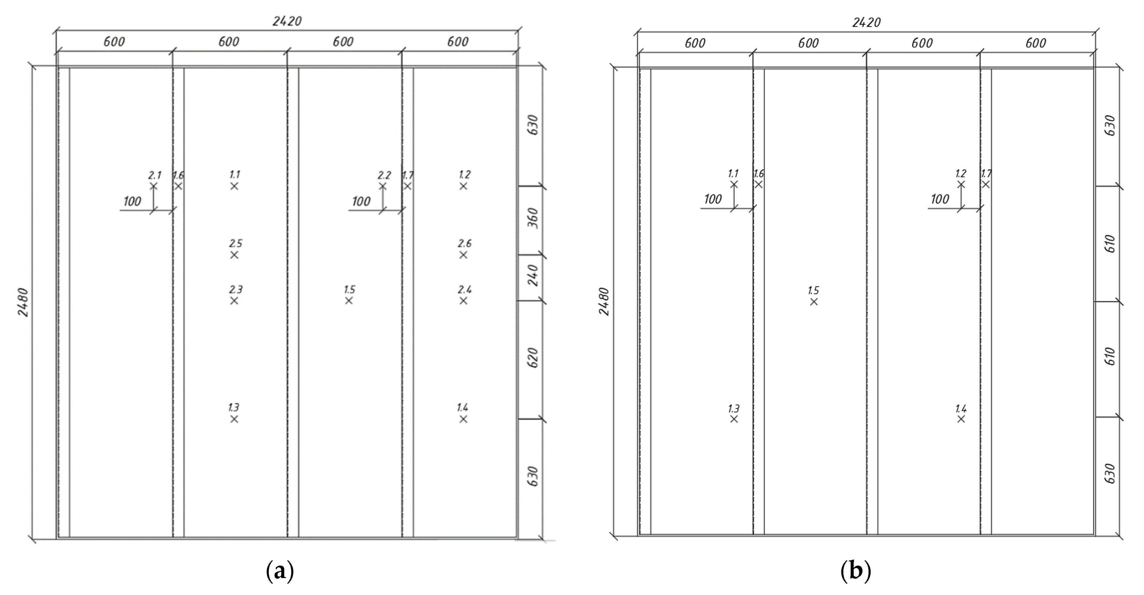
The temperature on the test samples was determined by cable thermoelectric chromel–alumel thermocouples designed as described in IMO Resolution A.754 (18) [26] and mounted on the unheated surfaces of the sample (Figure 3). The location of the thermocouples for the H-60 bulkhead is the same as on the H-120 bulkhead.
The A-15 and A-60 (sample No. 1 and sample No. 2) bulkheads were built following IMO Resolution A.754 (18) [26] and insulated on the stiffened side not exposed to the fire. The mineral wool panels are secured to the bulkhead plate through steel pins and washers welded with a pitch of 300 mm.
Fire tests of A-15 and A-60 (sample No. 1) class bulkheads were performed at RINA Services Spa (Genoa, Italy); fire test of A-60 (sample No. 2) class bulkhead was performed at FGBU VNIIPO EMERCOM of Russia (Balashikha, Moscow region, Russia). The bulkheads were tested in the vertical position exposing to the fire the uninsulated bulkhead side, mounted within a steel restraint frame having a refractory concrete lining 50 mm thick. The temperature on the test samples was measured by cable thermoelectric chromel–alumel thermocouples, installed in the amount of 7 pieces on the unheated surfaces of the sample.
The A-15 bulkhead has the following external dimensions: height 3020 mm, width 3020 mm, thickness 44.5/69.5 mm. The steel sheet thickness of 4.5 mm with the pins on the stiffeners at a distance of 600 mm was insulated with one layer of mineral wool: 40 mm PAROC Marine Fire Slab (Helsinki, Finland) with a density of 80 kg/m³.
The A-60 bulkhead (sample No. 1) has the following external dimensions: height 3020 mm, width 2420 mm, thickness 65/90 mm. The steel sheet thickness of 5 mm with the pins on the stiffeners at a distance of 600 mm was insulated with two layers of mineral wool: 60 mm and 25 mm PAROC Fire Slab (Helsinki, Finland) with a density of 100 kg/m³.
The A-60 bulkhead (sample No. 2) has the following external dimensions: height 2480 mm, width 2420 mm, thickness 54.5/79.5 mm. The steel sheet thickness of 4.5 mm with the pins on the stiffeners at a distance of 600 mm was insulated with two layers of 25 mm TIZOL-FLOT Fire (Yekaterinburg, Russia) with a density of 100 kg/m³.
Fire tests of the steel deck H-120 were carried out at the Fire Safety Scientific and Test Center of the FGBU VNIIPO EMERCOM of Russia (Balashikha, Moscow region, Russia). The temperature on the sample was measured by thermocouples, installed in the amount of 7 pieces on the unheated surface of the sample.
The H-120 deck has the following external dimensions: height 2440 mm, width 3040 mm, thickness 126/246 mm. The steel sheet thickness of 6 mm with the pins on the stiffeners at a distance of 600 mm was insulated with two layers of 60 mm Rockwool mineral wool panels with a density of 100 kg/m³.
2.2. Simulation of Bulkhead and Deck Section Heating
SP ELCUT allows solving tasks related to the heating of structures [36]. All calculations of the structures are performed by the finite element method based on the two-dimensional finite element model in the ELCUT software. To solve the task, it is necessary to specify the geometry, describe the properties of the medium and define the boundary conditions. The input of the task parameters consists of marks divided into three groups [35]:
Block marks that describe the material properties in the model;
Rib marks describing the boundary conditions on the outer and inner surfaces of the model;
Vertex marks that describe the anchoring conditions (boundary conditions) applied to certain points in the model.
In the simulation of heating, the thermal conductivity equation is used in the flat case (3) [37]:
where is the temperature in °C; is the time in seconds; means the components of the thermal conductivity tensor in W/(m·K); is the specific power of heat source in W/m3; is the specific heat capacity in J/(kg·K); and is the density in kg/m3.
A number of boundary conditions, such as temperature, heat flow, convection and radiation, are set at the outer and inner boundaries of the computational domain. The value of is given as a linear function of coordinates. The heat flow is described by the following Relations (4) and (5) [35]:
where is the normal component of the density vector of heat flow, where “+” and “−” mean “left of the border” and “right of the border,” respectively, in W/m2; is the power surface of the source for the inner border, for the outer, the known value of heat flow through the border in W/m2.
Convective heat transfer is determined according to (6) [38]:
where is the convective heat transfer coefficient in W/m2·K; is the ambient temperature in K.
The radiation condition is set at the outer border of the model; the radiation heat transfer is determined according to (7) [35]:
where is the Stefan–Boltzmann constant in W/(m2 · K4); is the surface absorption coefficient; and is the temperature of an absorbing medium in K.
Simulations were performed for bulkheads and deck under hydrocarbon and standard fire regimes.
Initial steel characteristics: steel grade D36 [39]; density 7800 kg/m3; thermal conductivity and heat capacity are variable depending on temperature (values are taken from the program reference book). The boundary conditions are presented in Table 2.
The characteristics of the mineral wool for the different bulkheads and deck are shown in Table 3. It is assumed that the density value does not change during heating. The value of heat capacity is assumed to be averaged for all types of mineral wool according to manufacturer’s website and [41]; the trend of heat capacity change with temperature is assumed according to [42]. Moreover, the main influence on the heat transfer in the solid material layer has thermal conductivity [37].
3. Results and Discussion
3.1. Experimental and Simulation Results
For the H-0 bulkhead, the fire test was stopped at 122 min according to the requirements for this class of bulkheads (the limit condition for H-0 bulkheads is loss of integrity (E)). When the required time was reached, no smoke and flame penetration to the unheated side was observed, the integrity of the sample was preserved, and the deflection of the sample in the center of the bulkhead (60 mm) and the changing of the color of the open surface to yellow were recorded. According to the test results, it was found that the H-0 bulkhead with a steel sheet thickness of 4.5 mm, insulated with mineral wool with a thickness of 60/125 mm and a density of 150 kg/m³, has fire resistance under the action of a hydrocarbon fire regime for at least 30 min before reaching the parameter of thermal insulating capacity (I) and at least 120 min before reaching the parameter of loss of integrity due to the temperature increase on the unheated surface of the structure on average more than 140 °C. According to the DIFT report, the H-0 bulkhead may also be classified as H-30 regarding the experimental data obtained.
For the H-60 bulkhead, the fire test was stopped at 123 min when the critical temperature on the unheated surface of the structure reached an average of more than 140 °C (the technical customer’s request extended the test), no smoke and flame penetration on the unheated side was observed, the integrity of the sample was preserved, and the deflection of the sample in the center of the bulkhead (42 mm) and the changing of the color of the open surface to yellow were recorded. According to the test results, it was found that the H-60 bulkhead with a steel sheet thickness of 5 mm, insulated with mineral wool with a thickness of 70/110 mm and a density of 150 kg/m³, has fire resistance under the action of a hydrocarbon fire regime for at least 120 min.
For the H-120 bulkhead, the fire test was stopped at 125 min when the critical temperature on the unheated surface of the structure reached an average of more than 140 °C (the technical customer’s request extended the test), no smoke and flame penetration on the unheated side was observed, the integrity of the sample was preserved, and the deflection of the sample in the center of the bulkhead (24 mm) and the changing of the color of the open surface to yellow were recorded. According to the test results, it was found that the H-120 bulkhead with a steel sheet thickness of 5 mm, insulated with mineral wool with a thickness of 90/150 mm and a density of 150 kg/m³, has fire resistance under the action of a hydrocarbon fire regime for at least 120 min.
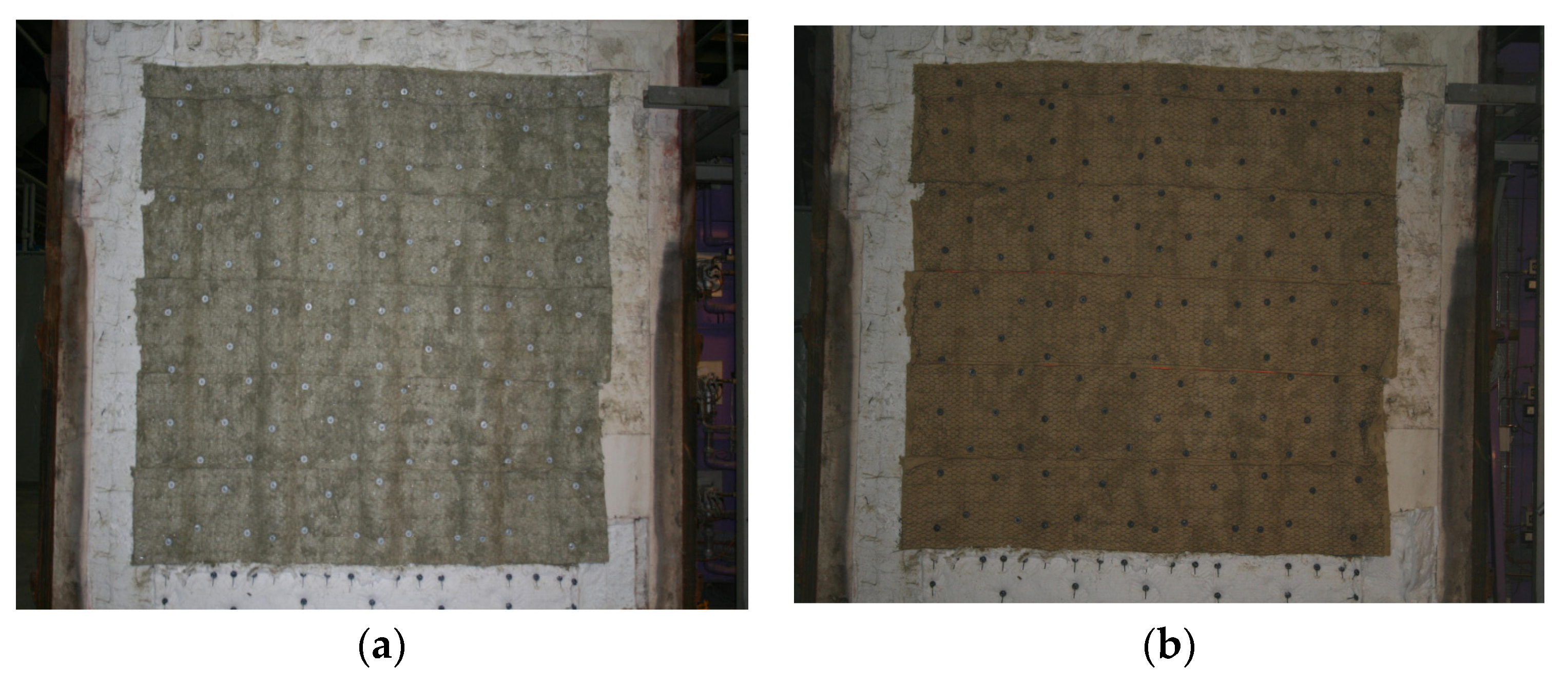
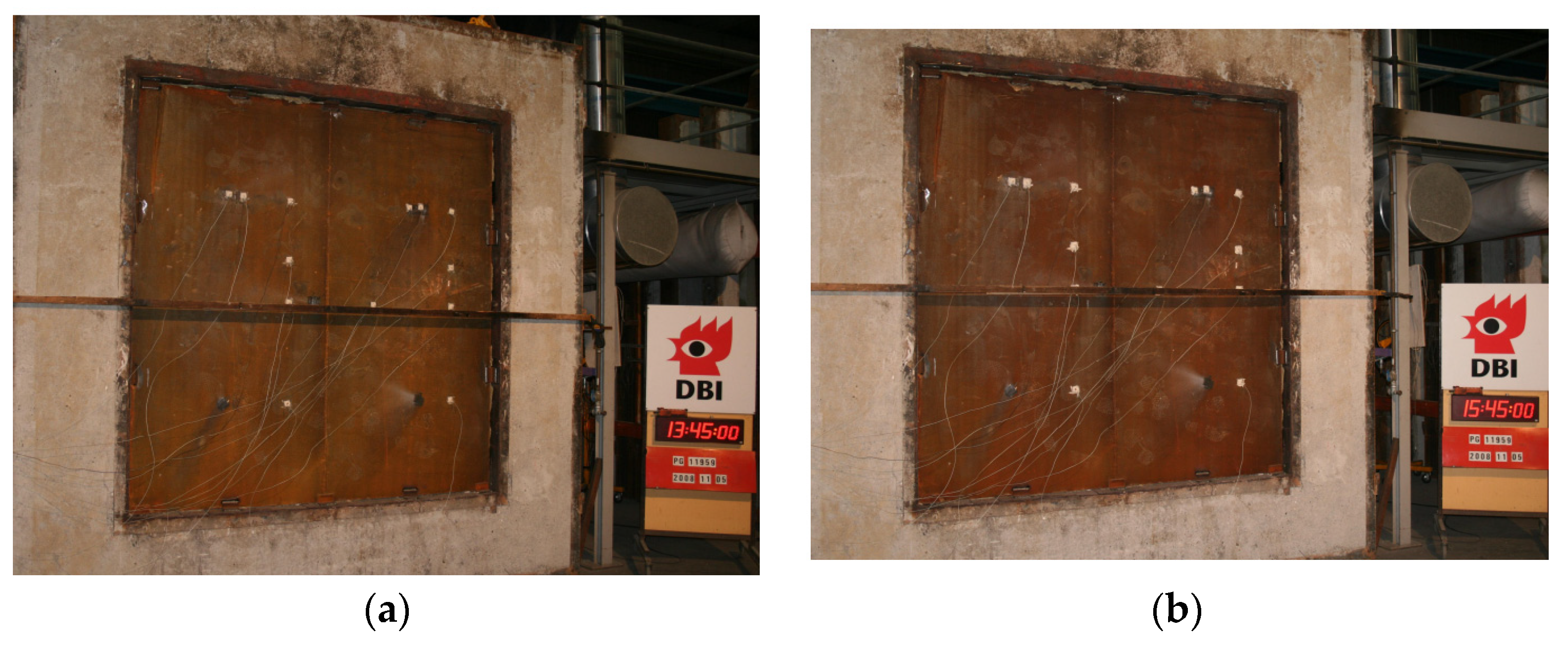
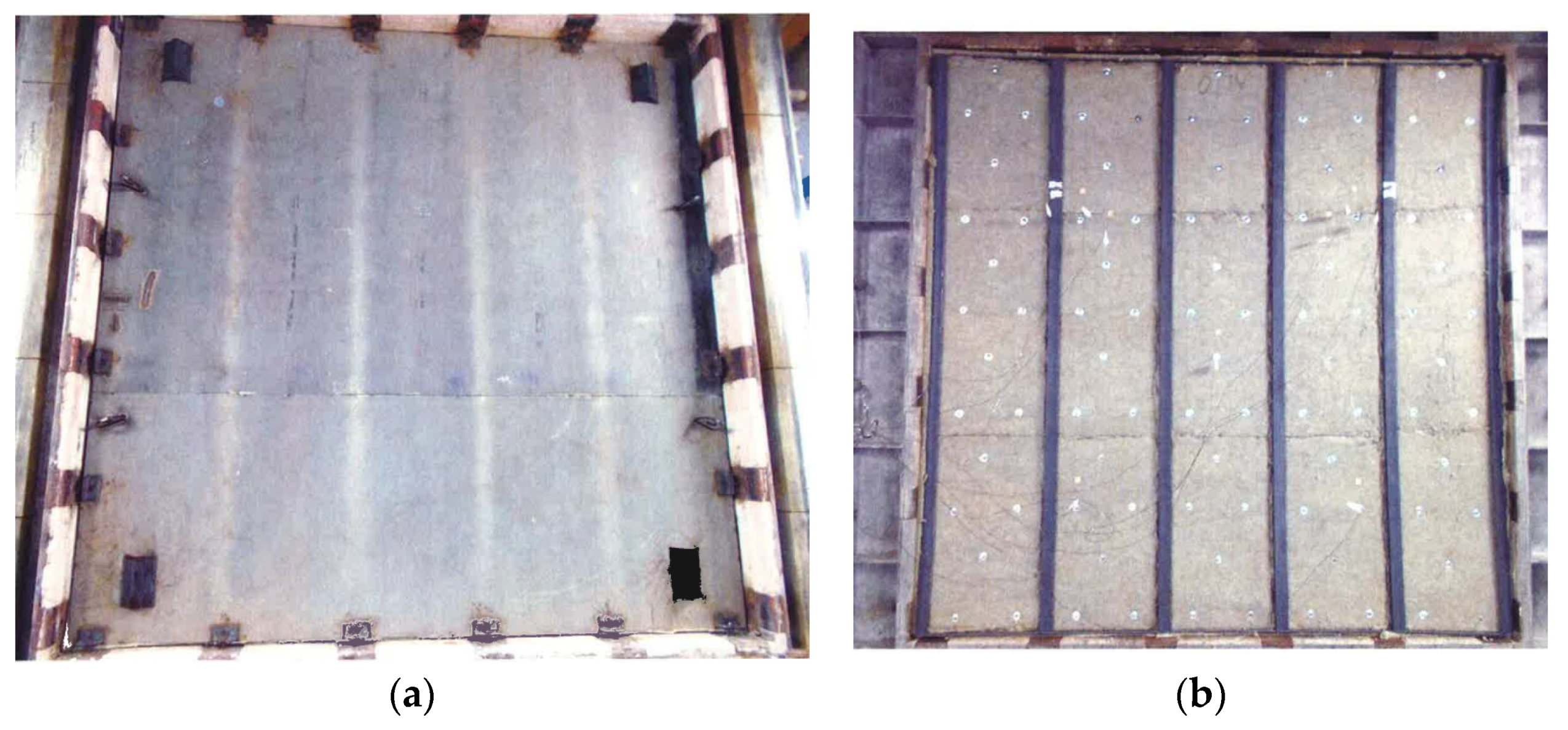
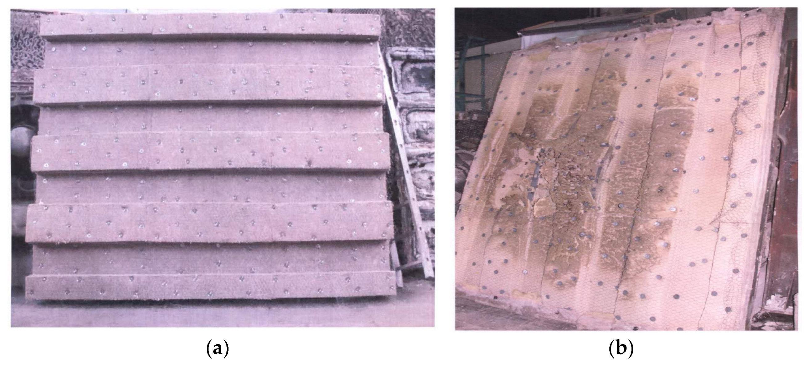
The H-class bulkheads’ appearance before and after the fire test did not change, and the deflection at the center of the bulkheads did not reach the limit value of l/20 in each test [27]. For example, the heated and unheated sides before and after the fire test of H-120 bulkheads (Figure 4 and Figure 5) and mineral wool after the fire test of H-120 and H-0 bulkheads (Figure 6) are shown.
For the A-15 bulkhead, the fire test was stopped at 30 min according to the requirements. No smoke and flame penetration on the unheated side was observed, the sample’s integrity was preserved, and the deflection of the sample in the center of the bulkhead (105 mm) was recorded. No cracks and holes in the sample were found. According to the test results, it was found that the A-15 bulkhead with a steel sheet thickness of 4.5 mm, insulated with mineral wool with a thickness of 40 mm and a density of 80 kg/m³, has fire resistance under the action of a standard fire regime for at least 15 min.
For the A-60 bulkhead (sample No. 1), the fire test was stopped at 60 min when the critical temperature on the unheated surface of the structure reached an average of more than 140 °C. No smoke and flame penetration on the unheated side was observed, the sample’s integrity was preserved, and the deflection of the sample in the center of the bulkhead (70 mm) was recorded. No cracks and holes in the sample were found. According to the test results, it was found that the A-60 bulkhead (sample No. 1) with a steel sheet thickness of 5 mm, insulated with mineral wool with a thickness of 60/85 mm and a density of 100 kg/m³, has fire resistance under the action of a standard fire regime for at least 60 min.
For the A-60 bulkhead (sample No. 2), the fire test was stopped at 60 min according to the customer’s requirements. No smoke and flame penetration on the unheated side was observed, and the integrity of the sample was preserved. No cracks, holes or other visible changes on the sample were found, and the deflection value was not measured. According to the test results, it was found that the A-60 bulkhead (sample No. 2) with a steel sheet thickness of 4.5 mm, insulated with mineral wool with a thickness of 50/75 mm and with a density of 100 kg/m³, has fire resistance under the action of a standard fire regime for at least 60 min.
Considered A-class bulkheads did not change their appearance before and after the fire test, and the deflection at the center of the bulkheads did not reach the limit value of l/20 in each test [27]. For example, the heated and unheated sides after the fire test of the A-15 bulkhead are shown (Figure 7).
For the deck H-120, the fire test was stopped at 125 min when the critical temperature on the unheated surface of the structure reached an average of more than 140 °C. No smoke and flame penetration on the unheated side was observed, and the integrity of the sample was preserved. No cracks, holes or other visible changes on the sample were found, and the deflection value was not measured (Figure 8). According to the test results, it was found that deck H-120, with a steel sheet thickness of 6 mm, insulated with mineral wool with a thickness of 120/240 mm and a density of 100 kg/m³, has fire resistance under the action of a hydrocarbon fire regime for at least 120 min.
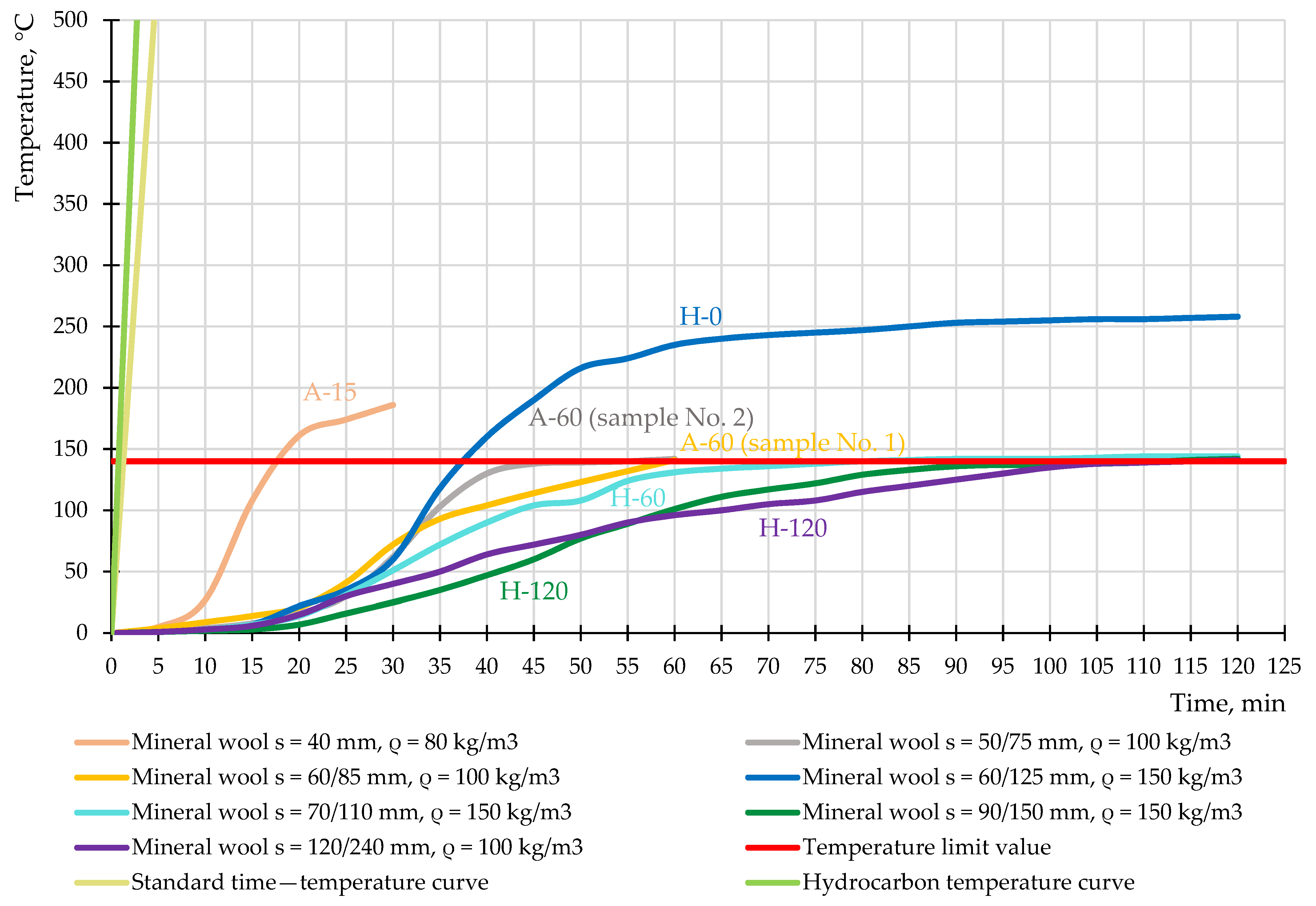
Figure 9 shows the time–temperature curves of the bulkheads and deck during the fire test. The graph shows the averaged values of the difference between the values of thermocouples located directly on the unheated surface of the sample and the initial ambient temperature (20 °C, Table 3).
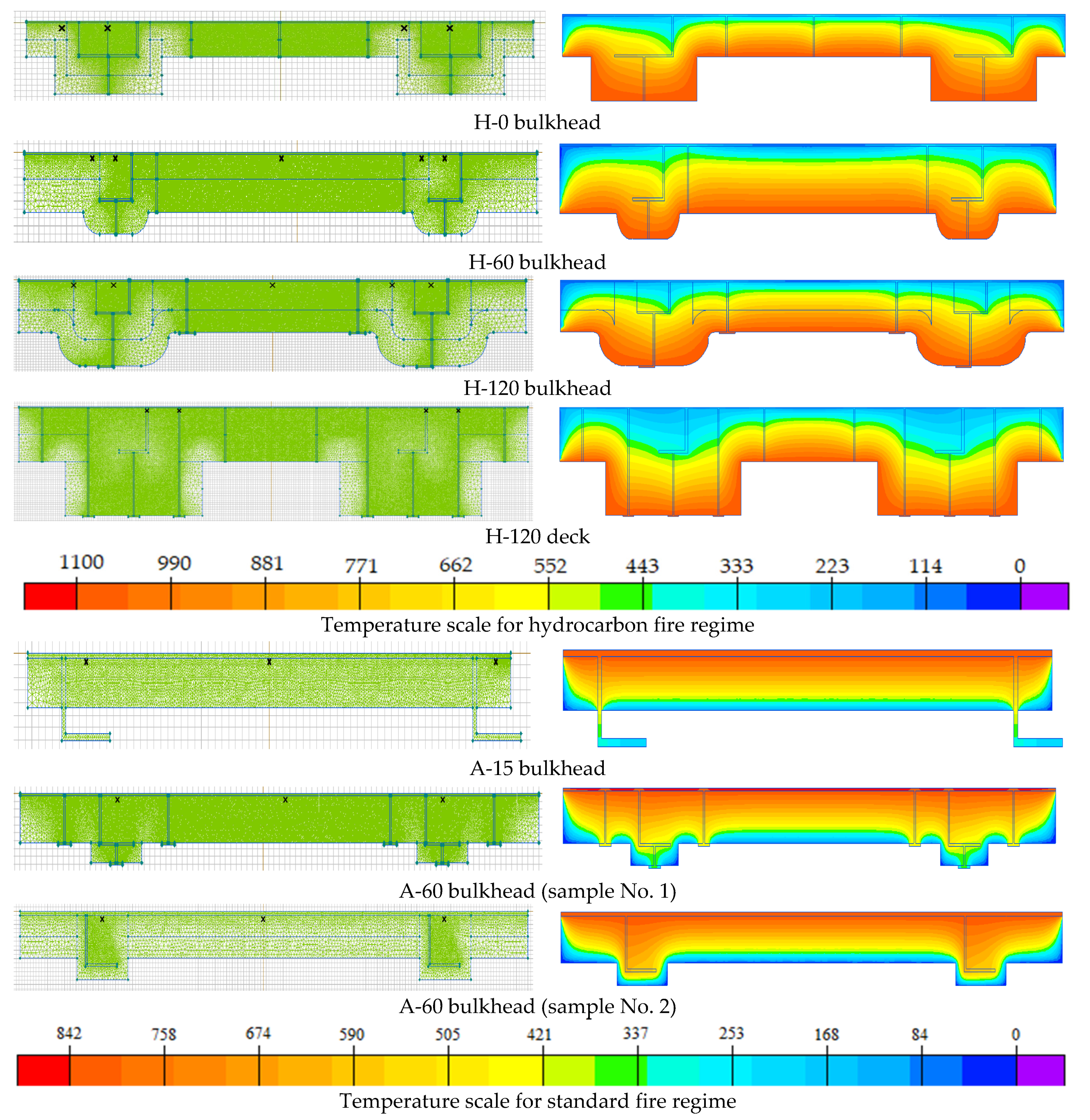
As a result of the simulation, visualizations of the heating of the experimental bulkheads and deck were obtained (Figure 10). The location of the thermocouples on the structures is shown in the analytical model. Each analytical model represents ¼ of the structure since it consists of similar and repeating fragments. For H-class bulkheads and H-120 deck, the fire exposure was from the mineral wool side, and for A-class bulkheads, from the steel plate side.
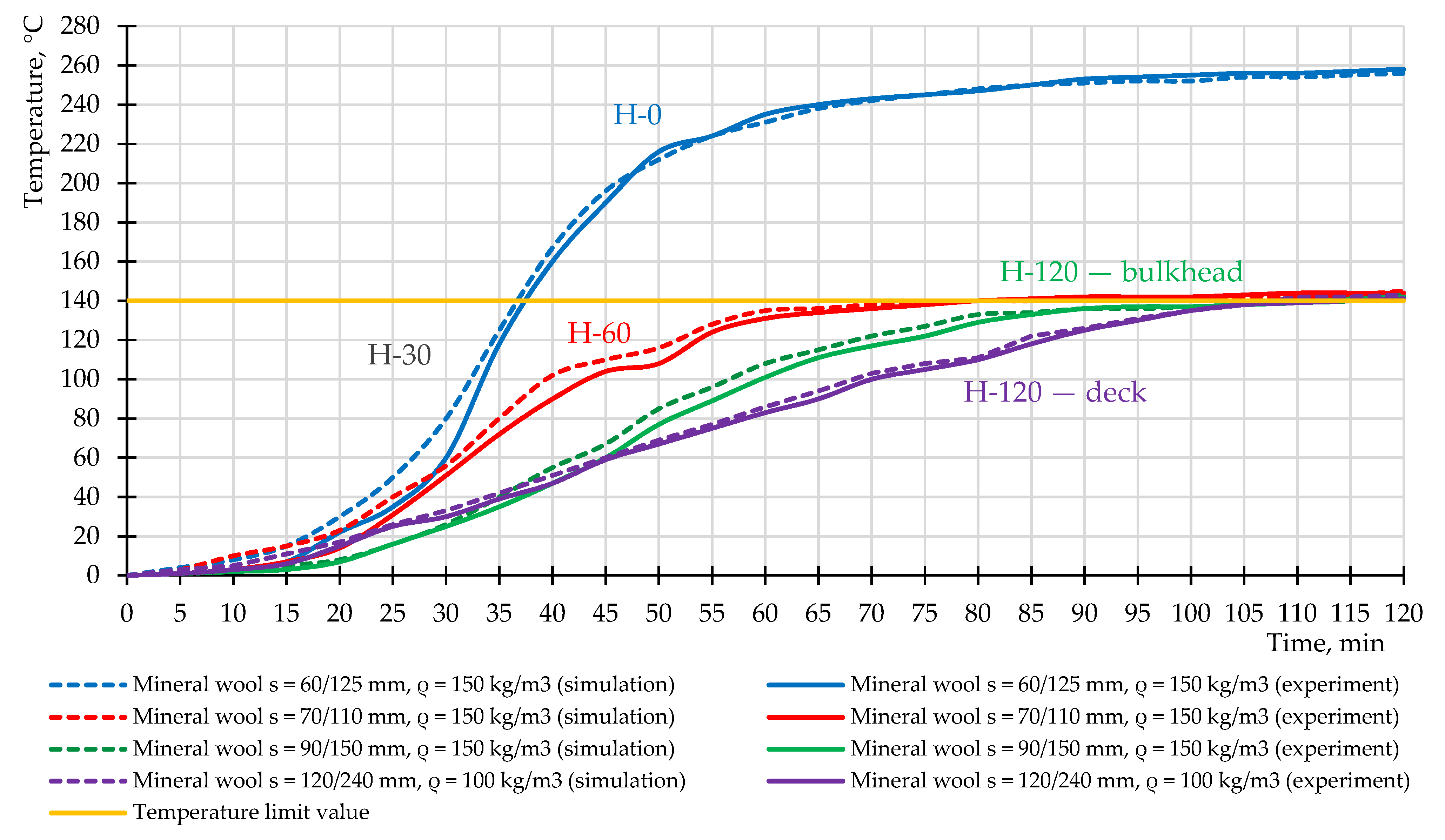
The temperature–time dependences at the thermocouple location on the unheated surface were obtained for H-class bulkheads and deck H-120 (Figure 11).
The graph shows the averaged values of the difference between the values of thermocouples located directly on the unheated surface of the sample and the initial ambient temperature (20 °C, Table 3). The different location of the thermocouples over the cross-section of the samples is shown in Figure 10. Heat and mass transfer processes were not considered in the modeling.
The results of the simulation show excellent correlation of the results (difference in values not more than 5%), except for the results for the H-0 bulkhead (25% in the range of 20 to 30 min), which has a smaller plate thickness (60 mm) compared to the other samples. Mineral wool is a dry fire retardant; however, it contains organic substances and water (Table 3). At a sharp temperature effect in the hydrocarbon fire regime in the range from 30 to 100 °C, the processes of heat and mass transfer are intensified, which may explain the excess of simulation results compared with the experimental values of temperatures.
Analysis of Figure 11 shows that the graph for the H-0 bulkhead grows more rapidly because the bulkhead warms up faster due to the fact that it has a smaller plate thickness (60/125 mm) at the same density (150 kg/m3). The graph for the deck H-120 with lower density (100 kg/m3) during the first 30 min shows higher temperature values compared to the H-120 bulkhead (150 kg/m3); after 45 min, due to the higher insulation thickness (120/240 mm), the graph for the deck H-120 shows a smoother temperature increase until the limit value is reached.
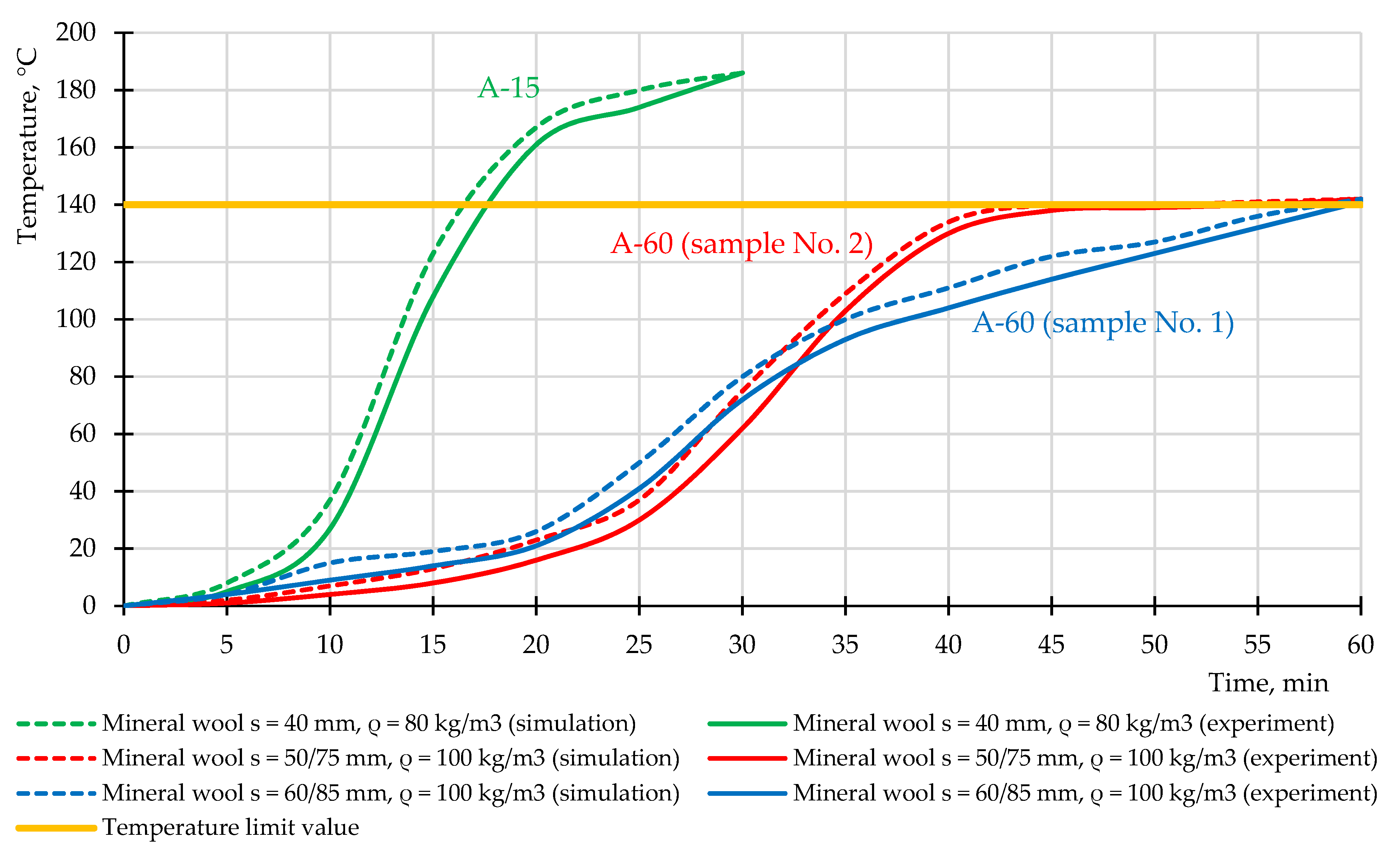
The temperature–time dependences at the thermocouple location on the unheated surface were obtained for A-class bulkheads (Figure 12).
Analysis of Figure 12 shows that the graph for the A-15 bulkhead grows more rapidly because the bulkhead warms up faster due to the fact that it has a smaller plate thickness (40 mm) and a lower density (80 kg/m3) while the A-60 bulkheads have higher values: density 100 kg/m3 and plate thickness 60/85 mm for sample No. 1 and 50/75 mm for sample No. 2. Samples No. 1 and No. 2 for A-60 bulkheads with a density of 100 kg/m3 have similar dynamics of temperature increase up to 30 min, then sample No. 1 continues to heat uniformly, while sample No. 2, which has a plate thickness of 10 mm less than the thickness of sample No. 1, increases sharply and reaches equilibrium state after 40 min of heating.
In the example of the H-0 bulkhead, the deflection in the center of the considered structure under the thermal load was calculated in SP ELCUT using the connection of tasks of unsteady heat transfer and mechanical stresses and strains, which resulted in a deformation diagram shifted by 63 mm relative to the original position (Figure 13).
According to [27], the limit value of deflection at the center of the bulkhead is determined according to (8):
Thus, the deflection value obtained during the experiment (60 mm) and from the simulation (63 mm) does not exceed the acceptable value and confirms that the H-0 bulkhead subjected to high-temperature fire exposure maintains its integrity throughout the test.
3.2. Discussion
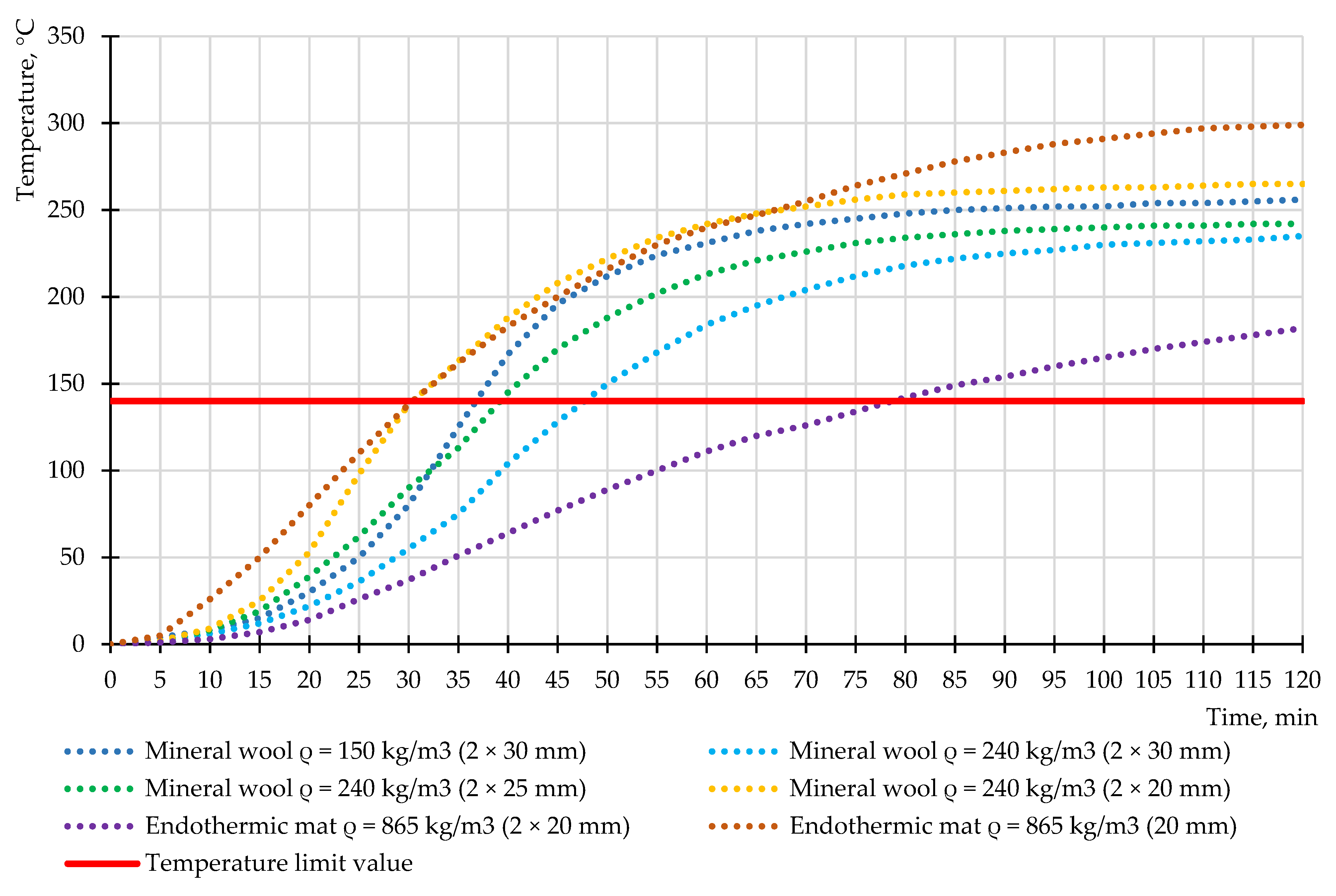
The calculated temperature values on the considered structures, obtained from the simulation results in the SP ELCUT, perfectly correlate with the experimentally obtained temperature values in any time period. In the example of the H-0 bulkhead, the thickness of used mineral wool was evaluated, and other variants of the rate of consumption of mineral wool under the hydrocarbon fire regime were presented (Figure 14). The choice of the bulkhead is justified by the maximum temperatures obtained from the experiment and simulation. The graph shows the averaged values of the difference between the values of thermocouples located directly on the unheated surface of the sample and the initial ambient temperature (20 °C, Table 3). The different locations of the thermocouples over the cross-section of the samples are shown in Figure 10. The H-0 bulkhead is also certified as H-30. According to the initial data, the H-0 bulkhead has two layers of mineral wool with a total thickness of 60 mm (2 × 30 mm) with a density of 150 kg/m³. One of the ways to reduce the consumption of mineral plates is to increase their density. For example, when choosing the density of mineral wool as 240 kg/m³ (PAROC mineral wool [43]), the temperature at 30 min is reduced by 40 °C, which shows the overconsumption of used fire protection. There are two variants to reduce the thickness of mineral wool with a density of 240 kg/m3: using two layers of thickness of 25 mm and two layers of thickness of 20 mm. At a total thickness of 40 mm (2 × 20 mm), the temperature at 30 min reaches 138 °C, which shows optimal thickness use, providing the required fire protection efficiency in hydrocarbon fire mode.
Endothermic mats with high fire-resistance limits and high cost relative to mineral wool are also used as insulation systems in O&G [44]. Thermophysical characteristics were taken for flexible endothermic mat “3M Interam” with a thickness of 20 mm with basalt fiber and endothermic ingredients (Table 4).
When using an endothermic mat with a thickness of 40 mm, the temperature at 30 min reaches 37 °C, which proves the need to reduce the consumption of the used insulation system. When reducing the thickness of the endothermic mat to 20 mm, the temperature at 30 min reaches 139 °C, which proves the use of optimal thickness, at which the required fire protection efficiency in hydrocarbon fire mode is provided.
The values of coefficients of thermal conductivity and heat capacity of mineral wool manufacturers Rockwool (1), PAROC (2) and TIZOL (3) were clarified (Table 5). The calculated values of thermophysical characteristics obtained from the simulation correlate with the values in Table 3. For temperatures above 400 °C, the obtained values require experimental confirmation but can be used in solving thermal engineering tasks with unsteady thermal conductivity.
Analysis of Table 5 shows that the best characteristics (the lowest thermal conductivity in the range from 0 to 1000 °C) to perform the functions of fire protection and thermal insulation have material 1 (Rockwool). As stated in Section 2, the heat capacity values were given the same and averaged for all types of mineral wool due to the lack of accurate data at elevated temperatures from manufacturers.
4. Conclusions
Test methods of the fire resistance of steel structures for hydrocarbon fuel transportation facilities are similar to the requirements of onshore structures of the oil and gas complex. The same parameters under different fire regimes are applied: loss of integrity and thermal insulating capacity. Based on experimental results, simulation of the fire resistance of bulkheads of different classes and decks for an offshore platform was carried out. It was found that to obtain the required fire-resistance limits of bulkheads in standard fire conditions (A-class), mineral wool with a density of 80–100 kg/m2 and fire protection material consumption of 40 to 85 mm (plate thickness) should be used; hydrocarbon mode (H-class) requires the use of the densest mineral wool (from 100 kg/m2) with a material consumption of 60–150 mm. Thus, to protect steel decks and bulkheads in a hydrocarbon fire with a structural steel thickness of 4.5–5 mm, it is necessary to use 30–40% more thermal insulation and apply the highest density of fire-retardant material compared to the standard fire.
Simulations have shown that constructing the H-0 bulkhead certified as H-30 (for loss of integrity and thermal insulating capacity) and H-0 (for loss of integrity) with mineral wool with a density of 150 kg/m3 and a thickness of 60 mm is not optimal in relation to fire protection overage.
The simulated H-0 bulkhead with mineral wool with a density of 240 kg/m3 and an insulation thickness of 40 mm and endothermic mat with a density of 865 kg/m3 and a thickness of 20 mm can reduce the consumption of fire protection by 33% and 66%, respectively, providing the required fire resistance H-30. It is expected in the future to use fire protection and thermal insulation plates containing a combination of super-thin basalt fiber and ceramic fibers, designing a high fire-resistance rating and an adequate final product cost.
The obtained values of the coefficients of thermal conductivity and heat capacity for mineral wool can be used in the calculation of structures for fire resistance with the considered type of fire protection in the temperature range from 0 to 1000 °C.
Author Contributions
Conceptualization, M.G.; data curation, D.S. All authors have read and agreed to the published version of the manuscript.
Funding
The research is partially funded by the Ministry of Science and Higher Education of the Russian Federation under the strategic academic leadership program “Priority 2030” (Agreement 075-15-2021-1333 dated 30 September 2021).
Institutional Review Board Statement
Not applicable.
Informed Consent Statement
Not applicable.
Data Availability Statement
Testing laboratories of the FGBU VNIIPO EMERCOM of Russia, Danish Institute of Fire and Security Technology and RINA Services Spa.
Acknowledgments
The authors would like to thank Nikolai Ivanovich Vatin, Peter the Great St. Petersburg Polytechnic University, St. Petersburg, Russia, for valuable and profound comments.
Conflicts of Interest
The authors declare no conflict of interest.
References
- Andryushkin, A.Y.; Kirshina, A.A.; Kadochnikova, E.N. The evaluation of the fire-retardant efficiency of intumescent coatings of steel structures exposed to high-temperature gas flows. Pozharovzryvobezopasnost/Fire Explos. Saf. 2021, 30, 14–26. [Google Scholar] [CrossRef]
- Gravit, M.; Zimin, S.; Lazarev, Y.; Dmitriev, I.; Golub, E. Fire Simulation of Bearing Structures for Natural Gas Module Plant. Adv. Intell. Syst. Comput. 2020, 365–376. [Google Scholar] [CrossRef]
- Imran, M.; Liew, M.S.; Nasif, M.S.; Gracia, E.M.; Danyaro, K.U.; Niazi, M.U. Thermal and Mechanical Response of Partially Protected Steel I-Beam under Fire. MATEC Web Conf. 2018, 203, 06009. [Google Scholar] [CrossRef]
- Gravit, M.; Gumerova, E.; Bardin, A.; Lukinov, V. Increase of Fire Resistance Limits of Building Structures of Oil-and-Gas Complex Under Hydrocarbon Fire. Adv. Intell. Syst. Comput. 2018, 692, 818–829. [Google Scholar] [CrossRef]
- ISO 834-75. Elements of Building Constructions. Fire-Resistance Test Methods. General Requirements. Available online: https://docs.cntd.ru/document/9055248 (accessed on 2 November 2021).
- Dmochowska, A. Threats related to accidental release of LPG in rail transport. Zesz. Nauk. SGSP 2020, 73, 37–54. [Google Scholar] [CrossRef]
- Aksu, S. Assessing compartment-wide damage consequences in ships and offshore vessels using Fault Trees with System Location Attribution. Ocean Eng. 2019, 192, 106510. [Google Scholar] [CrossRef]
- Zakhmatov, V.D.; Tursenev, S.A.; Mironchev, A.V.; Chernyshov, M.V.; Ozerov, A.V.; Dorozhkin, A.S. Analysis of Existing and Justification of Applying New Automatic System for Fire-and-Explosion Prevention at Vessels, Ships, Offshore Oil Platform. Pozharovzryvobezopasnost/Fire Explos. Saf. 2018, 27, 50–63. [Google Scholar] [CrossRef]
- Kim, M.; Kim, G.; Oh, M. Optimized Fire Protection for Offshore Topside Structure with 3-Sides PFP Application. In Proceedings of the International Offshore and Polar Engineering Conference, San Francisco, CA, USA, 25–30 June 2017; pp. 740–746. [Google Scholar]
- Salazar-Domínguez, C.M.; Hernández-Hernández, J.; Rosas-Huerta, E.D.; Iturbe-Rosas, G.E.; Herrera-May, A.L. Structural Analysis of a Barge Midship Section Considering the Still Water and Wave Load Effects. J. Mar. Sci. Eng. 2021, 9, 99. [Google Scholar] [CrossRef]
- Nitonye, S.; Ezenwa, O. Calculation for Hull Strength Construction in Offshore Structures (A Case Study of 5000t Work Barge). West Afr. J. Ind. Acad. Res. 2013, 8, 3–12. [Google Scholar]
- Chandrasekaran, S.; Nagavinothini, R. Behavior of stiffened deck plates under hydrocarbon fire. Mar. Syst. Ocean Technol. 2020, 15, 95–109. [Google Scholar] [CrossRef]
- Niazi, U.M.; Nasif, M.S.; Bin Muhammad, M.; Imran, M. Integrated Consequence Modelling for Fire Radiation and Combustion Product Toxicity in offshore Petroleum Platform using Risk Based Approach. MATEC Web Conf. 2018, 225, 06013. [Google Scholar] [CrossRef] [Green Version]
- Manco, M.R.; Vaz, M.A.; Cyrino, J.C.R.; Landesmann, A. Evaluation of localized pool fire models to predict the thermal field in offshore topside structures. J. Braz. Soc. Mech. Sci. Eng. 2020, 42, 1–15. [Google Scholar] [CrossRef]
- Chandrasekaran, S.; Pachaiappan, S. Numerical analysis and preliminary design of topside of an offshore platform using FGM and X52 steel under special loads. Innov. Infrastruct. Solut. 2020, 5, 1–14. [Google Scholar] [CrossRef]
- Cirpici, B.K.; Wang, Y.; Rogers, B. Assessment of the thermal conductivity of intumescent coatings in fire. Fire Saf. J. 2016, 81, 74–84. [Google Scholar] [CrossRef]
- ABS Rules for Building and Classing Facilities on Offshore Installations. Rules for Building and Classing Facilities on Offshore Installations 2021. Available online: https://ww2.eagle.org/content/dam/eagle/rules-and-guides/current/offshore/63_rulesforbuildingandclassingfacilitiesonoffshoreinstallations_2021/fac-rules-july21.pdf (accessed on 8 November 2021).
- Seo, J.K.; Lee, S.E.; Park, J.S. A method for determining fire accidental loads and its application to thermal response analysis for optimal design of offshore thin-walled structures. Fire Saf. J. 2017, 92, 107–121. [Google Scholar] [CrossRef]
- A Study of SOLAS Regulation II-2/17 on Alternative Design and Arrangements for Fire Safety. Available online: https://core.ac.uk/download/pdf/38467591.pdf (accessed on 2 November 2021).
- Bureau of Shipping, A. ABS Rules for Building and Classing Mobile Offshore Units. Available online: https://ww2.eagle.org/content/dam/eagle/rules-and-guides/current/offshore/3_mobileoffshoreunits_2021/mou-part-5-july21.pdf (accessed on 3 December 2021).
- Russian Maritime Register of Shipping. Available online: https://rs-class.org/en/ (accessed on 22 November 2021).
- UL 1709. Rapid Rise Fire Tests of Protection Materials for Structural Steel. Available online: https://nd.gostinfo.ru/print.aspx?control=27&id=4546871&print=yes (accessed on 2 November 2021).
- EN 1363-2:1999. Fire Resistance Tests—Part 2: Alternative and Additional Procedures. Available online: https://nd.gostinfo.ru/document/6239985.aspx (accessed on 22 November 2021).
- Gravit, M.V.; Golub, E.V.; Antonov, S.P. Fire Protective Dry Plaster Composition for Structures in Hydrocarbon Fire. Mag. Civ. Eng. 2018, 3, 79. [Google Scholar] [CrossRef]
- Gravit, M.; Golub, E.; Klementev, B.; Dmitriev, I. Fire Protective Glass Fiber Reinforced Concrete Plates for Steel Structures under Different Types of Fire Exposure. Buildings 2021, 11, 187. [Google Scholar] [CrossRef]
- IMO Resolution A.754 (18). Recommendation for Testing Fire Resistance of Class “A”, “B” and “F” Slabs. Available online: http://www.rise.odessa.ua/texts/A754_18.php3 (accessed on 2 November 2021).
- Russian Government Standard GOST 30247.1-94. Elements of Building Constructions. Fire-Resistance Test Methods. Loadbearing and Separating Constructions. Available online: https://docs.cntd.ru/document/9055247 (accessed on 20 November 2021).
- Palfy, J. Guidance Notes on Alternative Design and Arrangements for Fire Safety. Available online: https://ww2.eagle.org/content/dam/eagle/rules-and-guides/current/design_and_analysis/122_altdesignandarrangforfiresafety/fire_safety_guidance_e-july10.pdf (accessed on 2 November 2021).
- Imran, M.; Liew, M.S.; Nasif, M.S.; Niazi, U.M.; Yasreen, A. Hydrocarbon Fire and Explosion’s Safety Aspects to Avoid Accident Escalation for Offshore Platform. ICIPEG 2016 2017, 801–808. [Google Scholar] [CrossRef]
- Imran, M.; Liew, M.S.; Nasif, M.S.; Niazi, U.M.; Yasreen, A. Hazard Assessment Studies on Hydrocarbon Fire and Blast: An Overview. Adv. Sci. Lett. 2017, 23, 1243–1247. [Google Scholar] [CrossRef]
- Jafarov, E. Causes and Consequences of Fire Emergencies on Oil and Gas Platforms. Revista Gestão Inovação e Tecnologias 2021, 11, 1253–1258. [Google Scholar] [CrossRef]
- Park, D.K.; Kim, J.H.; Park, J.S.; Ha, Y.C.; Seo, J.K. Effects of the structural strength of fire protection insulation systems in offshore installations. Int. J. Nav. Arch. Ocean Eng. 2021, 13, 493–510. [Google Scholar] [CrossRef]
- Zhukov, A.; Konoval’Tseva, T.; Bobrova, E.; Zinovieva, E.; Ivanov, K. Thermal insulation: Operational properties and methods of research. MATEC Web Conf. 2018, 251, 01016. [Google Scholar] [CrossRef]
- Gravit, M.; Dmitriev, I. Numerical Simulation of Fire Resistance of Steel Ship Bulkheads. Transp. Res. Procedia 2021, 54, 733–743. [Google Scholar] [CrossRef]
- ELCUT. Modeling of Two-Dimensional Fields by the Finite Element Method. Available online: https://elcut.ru/free_doc_r.htm (accessed on 6 January 2022).
- Dudin, M.O.; Vatin, N.I.; Barabanshchikov, Y. Modeling a set of concrete strength in the program ELCUT at warming of monolithic structures by wire. Mag. Civ. Eng. 2015, 54, 33–45. [Google Scholar] [CrossRef]
- Markus, E.S.; Snegirev, A.Y.; Kuznetsov, E.A. Numerical Simulation of a Fire Using Fire Dynamics; St. Petersburg Polytech-Press: St. Petersburg, Russia, 2021; p. 175. [Google Scholar]
- EN 1991-1-2: Eurocode 1: Actions on Structures—Part 1–2: General Actions—Actions on Structures Exposed to Fire. Available online: https://www.phd.eng.br/wp-content/uploads/2015/12/en.1991.1.2.2002.pdf (accessed on 25 October 2021).
- Russian Government Standard GOST 52927-2015. Rolled of Normal, Increased-and High-Strength Steel for Shipbuilding. Specifications. Available online: https://docs.cntd.ru/document/1200122434 (accessed on 6 January 2022).
- Recommendations for Optimizing the Operation of Fire Extinguishing, Smoke Removal and Ventilation Systems in Fires. Available online: https://fireman.club/literature/optimizatsiya-deystviy-sistem-pozharotusheniya-dyimoudaleniya-i-ventilyatsii-pri-pozharah-2005/ (accessed on 6 January 2022).
- Code of Practice. SP 50.13330.2012. Thermal Performance of the Buildings. Available online: https://docs.cntd.ru/document/1200095525 (accessed on 11 January 2022).
- Paudel, D.; Rinta-Paavola, A.; Mattila, H.-P.; Hostikka, S. Multiphysics Modelling of Stone Wool Fire Resistance. Fire Technol. 2021, 57, 1283–1312. [Google Scholar] [CrossRef]
- PAROC Building Insulation. Available online: http://kosko.ru/sites/kosko.ru/files/files/opisanie-svojstv-paroc.pdf (accessed on 28 November 2021).
- Gravit, M.; Shabunina, D. Structural Fire Protection of Steel Structures in Arctic Conditions. Buildings 2021, 11, 499. [Google Scholar] [CrossRef]
- Product Data Sheet “3M Interam” Endothermic Mat E-5A-4. Available online: https://www.aircraftspruce.com/catalog/pdf/05-00948tech.pdf (accessed on 18 December 2021).
Figure 1.
(a) Tanker with H-120 deck location. (b) Fragment of the section of the first deck with the arrangement of the bulkheads.
Figure 1.
(a) Tanker with H-120 deck location. (b) Fragment of the section of the first deck with the arrangement of the bulkheads.

Figure 2.
(a) Offshore platform with deck location. (b) Fragment of the section of the first deck with the arrangement of the bulkheads.
Figure 2.
(a) Offshore platform with deck location. (b) Fragment of the section of the first deck with the arrangement of the bulkheads.

Figure 3.
(a) Location of thermocouples on bulkhead H-120. (b) Location of thermocouples on bulkhead H-0.
Figure 3.
(a) Location of thermocouples on bulkhead H-120. (b) Location of thermocouples on bulkhead H-0.

Figure 4.
(a) Heated side of H-120 bulkhead before fire test. (b) Heated side of H-120 bulkhead after fire test.
Figure 4.
(a) Heated side of H-120 bulkhead before fire test. (b) Heated side of H-120 bulkhead after fire test.

Figure 5.
(a) H-120 bulkhead at the beginning of fire test. (b) H-120 bulkhead at the end of fire test.
Figure 5.
(a) H-120 bulkhead at the beginning of fire test. (b) H-120 bulkhead at the end of fire test.

Figure 6.
(a) Mineral wool after fire test of H-120 bulkhead. (b) Mineral wool after fire test of H-0 bulkhead.
Figure 6.
(a) Mineral wool after fire test of H-120 bulkhead. (b) Mineral wool after fire test of H-0 bulkhead.

Figure 7.
(a) Heated side of A-15 bulkhead at the end of the fire test. (b) Unheated side of A-15 bulkhead at the end of the fire test.
Figure 7.
(a) Heated side of A-15 bulkhead at the end of the fire test. (b) Unheated side of A-15 bulkhead at the end of the fire test.

Figure 8.
(a) Deck H-120 before the fire test. (b) Deck H-120 after the fire test.

Figure 9.
Temperature curves of experimental samples during fire tests.

Figure 10.
Analytical models of structures and thermocouple locations and visualization of the heating of bulkhead and deck structures.
Figure 10.
Analytical models of structures and thermocouple locations and visualization of the heating of bulkhead and deck structures.

Figure 11.
Experimental and simulated temperature curves of samples during the fire test under the hydrocarbon fire regime.
Figure 11.
Experimental and simulated temperature curves of samples during the fire test under the hydrocarbon fire regime.

Figure 12.
Experimental and simulated temperature curves of samples during the fire test under the standard fire regime.
Figure 12.
Experimental and simulated temperature curves of samples during the fire test under the standard fire regime.

Figure 13.
Deformation diagram of H-0 bulkhead under heat load.

Figure 14.
Variations of flame-retardant application for H-0 bulkhead.


Table 1.
Fire integrity of bulkheads separating adjacent spaces/areas.
| Spaces | (1) | (2) | (4) | (4) | (5) | (6) | (7) | (8) | (9) | (10) | (11) | (12) | |
|---|---|---|---|---|---|---|---|---|---|---|---|---|---|
| Control stations including central process control rooms | (1) | A-0 | A-0 | A-60 | A-0 | A-15 | A-60 | A-15 | H-60 | A-60 | A-60 | * | A-0 |
| Corridors | (2) | C | B-0 | B-0 A-0 | B-0 | A-60 | A-0 | H-60 | A-0 | A-0 | * | B-0 | |
| Accommodation spaces | (3) | C | B-0 A-0 | B-0 | A-60 | A-0 | H-60 | A-0 | A-0 | * | C | ||
| Stairways | (4) | B-0 A-0 | B-0 A-0 | A-60 | A-0 | H-60 | A-0 | A-0 | * | B-0 A-0 | |||
| Service spaces (low risk) | (5) | C | A-60 | A-0 | H-60 | A-0 | A-0 | * | B-0 | ||||
| Machinery spaces for category A | (6) | * | A-0 | H-60 | A-60 | A-60 | * | A-0 | |||||
| Other machinery spaces | (7) | A-0 | H-0 | A-0 | A-0 | * | A-0 | ||||||
| Process areas, storage tank areas, wellhead/manifold areas | (8) | (Symmetrical) | – | H-60 | H-60 | * | H-60 | ||||||
| Hazardous areas | (9) | – | A-0 | * | A-0 | ||||||||
| Service spaces (high risk) | (10) | A-0 | * | A-0 | |||||||||
| Open decks | (11) | – | * | ||||||||||
| Sanitary and similar spaces | (12) | C | |||||||||||
Note: * The division is to be of steel or equivalent material, but is not required to be of an A-class standard.
Table 2.
Boundary conditions set in the SP ELCUT.
| Name of the Value | Value | Information Source |
|---|---|---|
| Degree of blackness of ship’s alloy steel | 0.35 | [40] |
| Degree of blackness of mineral wool | 0.92 | [40] |
| Degree of blackness of endothermic mat | 0.96 | [40] |
| Convection heat transfer coefficient at standard temperature regime, W/(m2 · K) | 25 | [38] |
| Convection heat transfer coefficient at hydrocarbon temperature regime, W/(m2 · K) | 50 | [38] |
| Surface absorption coefficient | 0.5 | [37] |
| The emissivity of steel | 0.8 | [37] |
| The emissivity of mineral wool | 0.7 | [37] |
| Initial ambient temperature, °C * | 20 | - |
| Time step for calculating the temperature gradient of the structure, second | 60 | - |
Note: * According to the test reports, the temperature measured by thermocouples in the furnace was determined as an absolute value, and the temperature on the unheated surface was recorded and displayed as the difference between the ambient temperature and the temperature on the unheated surface.
Table 3.
The main characteristics of mineral wool for structures.
| Structure/Manufacturer | ρ, KT/M3 | λ, W/(m·K) | Cp, J/(kg·K) | φ, % | Organic Substances, % | Thickness of Plates, mm | ||||
|---|---|---|---|---|---|---|---|---|---|---|
| 10 °C | 100 °C | 300 °C | 10 °C | 100 °C | 300 °C | |||||
| H-0 (Rockwool) | 150 | 0.034 | 0.045 | 0.078 | 840 | 860 | 900 | 0.24 | 1.30 | 60/125 |
| H-60 (Rockwool) | 150 | 0.034 | 0.045 | 0.078 | 840 | 860 | 900 | 0.20 | 0.40 | 70/110 |
| H-120 (Rockwool) | 150 | 0.034 | 0.045 | 0.078 | 840 | 860 | 900 | 0.20 | 0.40 | 90/150 |
| A-15 (PAROC) | 80 | 0.037 | 0.047 | 0.095 | 840 | 860 | 900 | 0.34 | 1.50 | 40/65 |
| A-60 (PAROC) * | 100 | 0.037 | 0.047 | 0.095 | 840 | 860 | 900 | 0.28 | 3.09 | 60/85 |
| A-60 (TIZOL) ** | 100 | 0.035 | 0.046 | 0.085 | 840 | 860 | 900 | 0.25 | 2.00 | 50/75 |
| H-120 (Rockwool) | 100 | 0.034 | 0.045 | 0.078 | 840 | 860 | 900 | 0.20 | 0.40 | 120/240 |
Note: * Sample No. 1; ** Sample No. 2.
Table 4.
Coefficients of thermal conductivity and heat capacity of the endothermic mat “3M Interam” as a function of temperature [45].
Table 4.
Coefficients of thermal conductivity and heat capacity of the endothermic mat “3M Interam” as a function of temperature [45].
| T, °C | 93 | 177 | 316 | 399 | 482 |
|---|---|---|---|---|---|
| λ, W/K·m | 0.151 | 0.175 | 0.100 | 0.118 | 0.140 |
| C, J/K·m | 1155 | 1155 | 1155 | 1155 | 1155 |
| ρ, kg/m3 | 865 | 865 | 865 | 865 | 865 |
Table 5.
Calculation coefficients of thermal conductivity and heat capacity of mineral wools.
| T, °C | 0 | 100 | 200 | 300 | 400 | 500 | 600 | 700 | 800 | 900 | 1000 |
|---|---|---|---|---|---|---|---|---|---|---|---|
| λ (1), W/K·m | 0.0340 | 0.0450 | 0.0595 | 0.0780 | 0.1021 | 0.1314 | 0.1669 | 0.2047 | 0.2432 | 0.2810 | 0.3195 |
| λ (2), W/K·m | 0.0370 | 0.0470 | 0.0652 | 0.0950 | 0.1384 | 0.1967 | 0.2589 | 0.3207 | 0.3826 | 0.4453 | 0.5086 |
| λ (3), W/K·m | 0.0350 | 0.0460 | 0.0729 | 0.0850 | 0.1196 | 0.1652 | 0.2222 | 0.2724 | 0.3229 | 0.3741 | 0.4269 |
| C, J/K·kg | 840 | 860 | 877 | 900 | 913 | 929 | 943 | 955 | 971 | 988 | 1004 |
Publisher’s Note: MDPI stays neutral with regard to jurisdictional claims in published maps and institutional affiliations. |
© 2022 by the authors. Licensee MDPI, Basel, Switzerland. This article is an open access article distributed under the terms and conditions of the Creative Commons Attribution (CC BY) license (https://creativecommons.org/licenses/by/4.0/).
Share and Cite
MDPI and ACS Style
Gravit, M.; Shabunina, D. Numerical and Experimental Analysis of Fire Resistance for Steel Structures of Ships and Offshore Platforms. Fire 2022, 5, 9. https://0-doi-org.brum.beds.ac.uk/10.3390/fire5010009
AMA Style
Gravit M, Shabunina D. Numerical and Experimental Analysis of Fire Resistance for Steel Structures of Ships and Offshore Platforms. Fire. 2022; 5(1):9. https://0-doi-org.brum.beds.ac.uk/10.3390/fire5010009
Chicago/Turabian StyleGravit, Marina, and Daria Shabunina. 2022. "Numerical and Experimental Analysis of Fire Resistance for Steel Structures of Ships and Offshore Platforms" Fire 5, no. 1: 9. https://0-doi-org.brum.beds.ac.uk/10.3390/fire5010009