Heat-Dissipation Performance of Nanocomposite Phase-Change Materials in a Twin-Heat-Source System


1
School of Energy and Environmental Engineering, Hebei University of Technology, Tianjin 300401, China
2
Department of Energy Sciences, Division of Heat Transfer, Lund University, SE-22100 Lund, Sweden
*
Author to whom correspondence should be addressed.
Fluids 2020, 5(4), 174; https://0-doi-org.brum.beds.ac.uk/10.3390/fluids5040174
Submission received: 28 August 2020
/
Revised: 30 September 2020
/
Accepted: 3 October 2020
/
Published: 7 October 2020
(This article belongs to the Special Issue Thermophysical Properties of Nanofluids - From Measurement to Interpretation)
Abstract
:In this paper, pure paraffin was mixed with CuO (high thermal conductivity) and Span-80 (as a dispersant). The CuO/paraffin nanocomposite phase-change materials (PCMs) were synthesized with mass fractions of 0.3%, 0.6%, and 1.2%, by a two-step method. Heat-transfer characteristics of the heat-pipe–PCMs module and effects of fan power and heating power on the performance of the cooling module in a twin-heat-source system were studied. For two heat sources under 10 W–10 W (heat source 1 with a power of 10 W and heat source 2 with a power of 10 W), the paraffin wax decreases the evaporator temperature by 14.4%, compared with cases without PCMs.
1. Introduction
Recently, phase-change materials (PCMs) have been widely used in electronics cooling due to their high heat storage capacity during phase-change processes [1]. Compared with the sensible heat storage, the latent heat storage provides higher energy density and more stable operating temperature. Paraffin wax is commonly taken as an organic phase-change material due to its advantages of stable chemical performance, high latent heat, low cost, and no supercooling [2]. However, the paraffin wax has a low thermal conductivity, which limits its application in various fields. This behavior can be improved by mixing multi-walled carbon nanotubes (CNTs), carbon nanofibers, and graphene nanoplatelets (GNPs) into the PCMs [3]. In addition, Wu et al. [4] found that paraffin with 3% CNTs showed 30.3% and 28.5% increases in thermal conductivities of the solid and liquid phases, respectively. Babapoord and Karimi [5] found that thermal conductivity of 6 wt.% Al2O3 nanocomposite PCMs increased by 141.2%, compared to paraffin wax. Arshad et al. [6] found that hybrid nano-enhanced PCMs had the highest thermal conductivity enhancement of 96% compared to pure paraffin. Li et al. [7] numerically and experimentally investigated the thermal behavior of microencapsulated PCMs saturated in a metal foam, and they found that it effectively improved the thermal conductivity of the PCMs for passive thermal management.
For the electronics cooling, Ren et al. [8] optimized pin-fin cascade microencapsulated PCMs/expanded graphite composite material, and the composite PCMs were used for thermal performance improvement of electronic equipment. Ling et al. [9] proposed an effective cooling method for electronic equipment by integrating PCMs with a three-dimensional oscillating heat pipe, and they found that the best performance was observed with a filling ratio of 34%–44%. Yang et al. [10] developed a PCM-based finned heat pipe radiator which prolonged the working duration 1.4–2.4 times compared to that of low melting point metal (Bi31.6In48.8Sn19.6). Krishna et al. [11] investigated the effect of different fan powers and heating powers on the temperature of the evaporator in a PCM cooling module. Yu et al. [12] studied heat dissipation of heat pipes with the PCM cooling in a multiple-heat-source system. It was found that phase-change material RT35 maintained temperature variations of the evaporator at a lower temperature.
In this paper, nano-CuO/paraffin composites are used to investigate heat-transfer characteristics of the heat pipe/PCM nanocomposite coupling module in a twin-heat-source system. For the finned heat pipe assisted with PCMs, effects of nanoparticle CuO on thermal properties of the paraffin have not been fully discussed in published references. A comparison of heat pipes with and without paraffin is conducted to investigate heat-transfer characteristics first, and then the effect of the nanoparticle addition is investigated by changing the mass fraction of the CuO nanoparticles. Finally, the effect of the cooling module performance is analyzed at various fan powers and heating powers.
2. Experimental Preparation
2.1. Experimental Materials and Instruments
Paraffin wax (Kmart Chemical Technology Company, Tianjin, China) has a melting temperature of 35~37 °C, and its thermal conductivity is 0.2 W/m·K. Latent heat and specific heat of paraffin wax are 172 kJ/kg and 2.1 kJ/kg·K, respectively. The nanoparticle CuO (Beijing Dekedao Gold Technology Company, Beijing, China) with an average particle size of 30 nm has a specific surface area of 13.1 m2/g, and its thermal conductivity is 37 W/m·K. The Span-80 (Kmart Chemical Technology Company, Tianjin, China) is made of sorbitan fatty acid ester. Accuracies of instruments are listed in Table 1.
2.2. Preparation of Composite PCMs
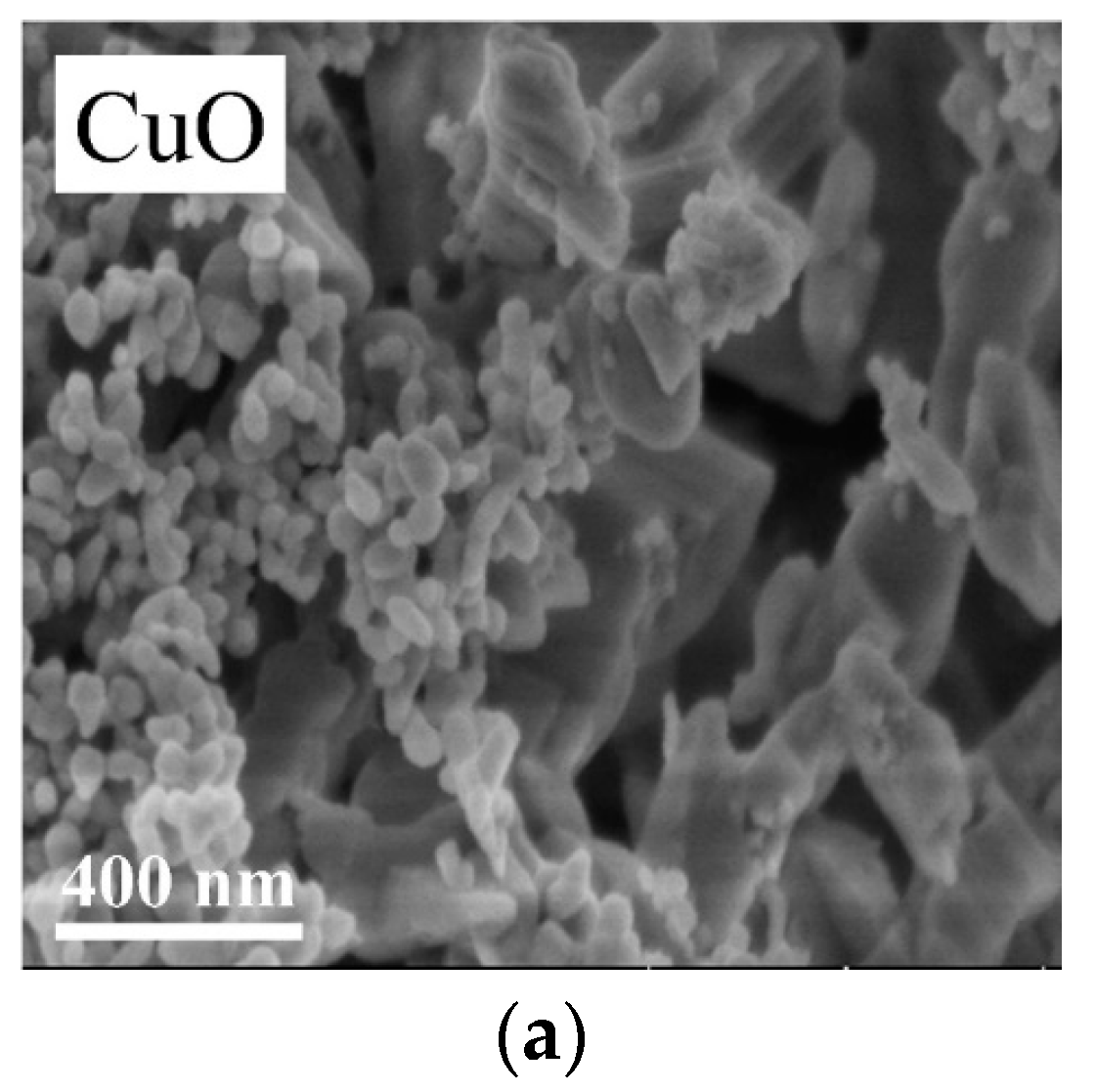
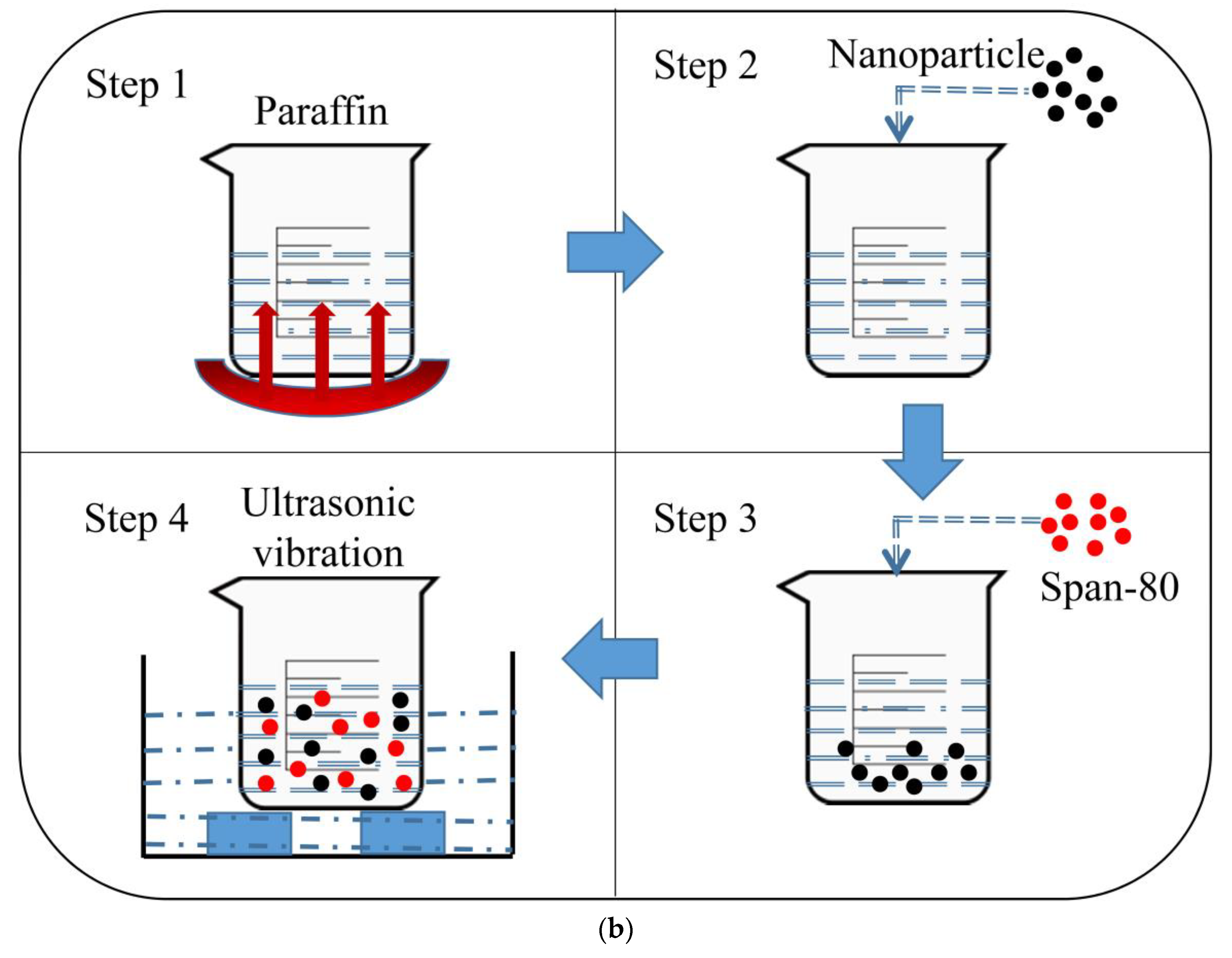
With paraffin wax as a base material, nano-CuO/paraffin composite PCMs are prepared by a two-step method. Then, 40 g of paraffin is accurately weighted by using an electronic scale (Shanghai Precision Instrument Co., Ltd., Shanghai, China) and put into a water bath (Changzhou Guohua Electric Co., Ltd., Changzhou, China). After the paraffin melts, different mass fractions of nanoparticles are mixed into the paraffin. Dispersant Span-80 and nanoparticles are mixed at a ratio of 1:1, 40 min ultrasonic oscillation at 40 kHz frequency and 70 °C were used in the preparation of the stable nanocomposite PCMs. Figure 1 shows nanoparticle images obtained by a scanning electron microscopy (SEM) and the preparation procedure of nanocomposite PCMs.
2.3. Experimental System
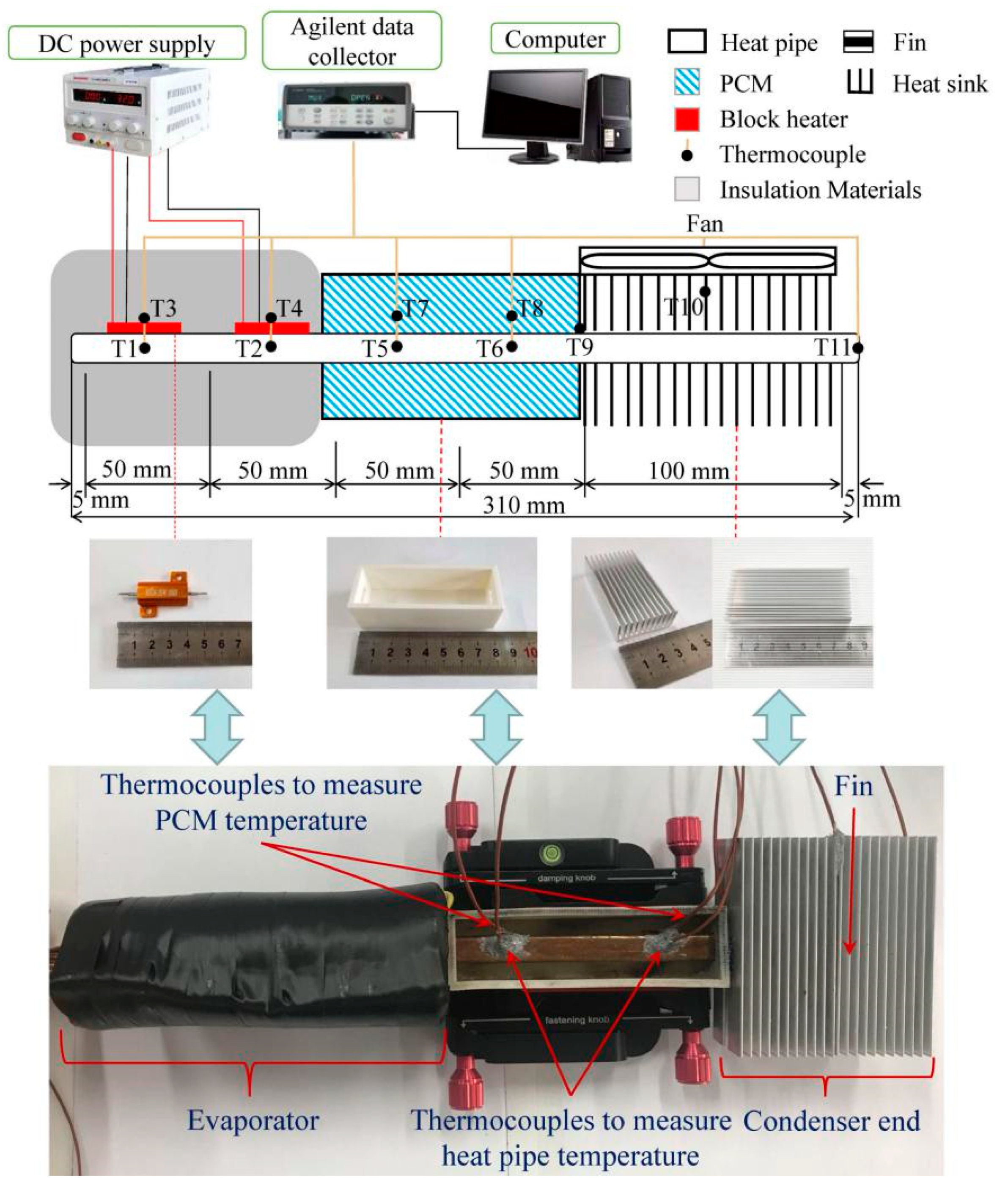
Figure 2 shows the system diagram of the device used to investigate the cooling performance of the heat-pipe–PCM module in a twin-heat-source system. The experimental setup consists of a copper heat pipe, a heat sink fin, a PCM tank, a cooling fan, two block heaters, two DC power supplies, a computer, and a data collector (Agilent Technologies Inc., California, United States). T-type thermocouples with an accuracy of ±0.5 °C were used to measure temperature values of the pipe and PCMs at different locations. The flat heat pipe made of copper has a length of 310 mm, a width of 11 mm, and a height of 2.7 mm. The thickness of the copper wall is 0.5 mm. The cooling module is divided into three parts, i.e., the evaporation end (with a length of 100 mm), the adiabatic end (with a length of 100 mm), and the condensation end (with a length of 100 mm). The heat in the experimental system is supplied to the evaporator end of the cooling module. A portion of the heat is absorbed by the PCMs filled in the PCM tank with a volume of 50 mL. The heat sink is connected to the heat pipe, using thermal conductive silica gel, and the total cooling area of the heat sink is 0.0112 m2.
2.4. Experimental Uncertainty Analysis
In order to provide a stable heat flow for the heat-pipe evaporator, an adjustable DC power supply is used. The stored thermal energy in the PCM is estimated as follows:
where Ti and Te are the initial and terminal temperatures of the PCM during the heating and cooling processes, respectively, and the corresponding values are calculated as follows:
The uncertainty of the PCM energy storage is calculated as follows:
Based on uncertainty analyses of the Agilent data collector and thermocouple instrument tests, the accuracy of the T-type thermocouple is ±0.5 °C. The accuracies of the current and voltage from the DC power supply are ±0.1 V and ±0.1 A, respectively. For the independent variables u, v, and w, the error can be calculated according to the law of the error propagation, as shown in Equation (5) [13]. The analysis of the present experimental uncertainty is shown in Table 2.
3. Results and Discussion
3.1. Effect of PCMs on the Cooling Performance
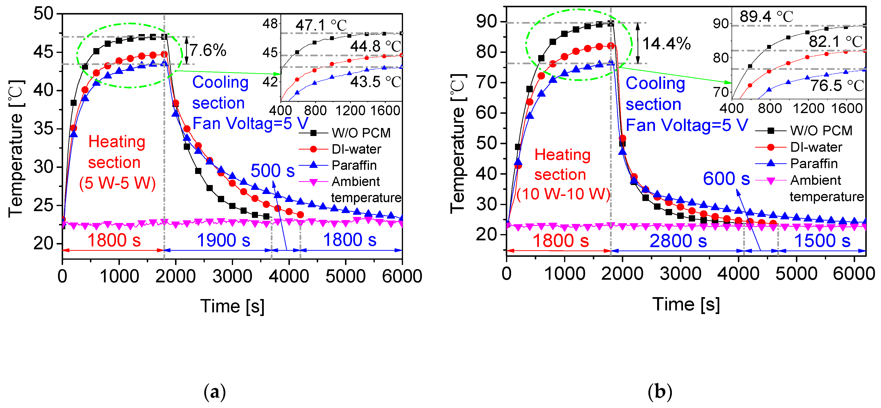
The temperature change of the evaporator end is investigated to analyze the heat-transfer intensity of the heat-pipe–PCM module in the twin-heat-source system. The evaporator temperature is calculated as the average temperature of the heat sources 1 and 2 (measured by thermocouples). Figure 3 shows variations of the evaporator temperature under different heat-source powers, using various PCMs with the same volume of 50 mL. When the heat sources 1 and 2 have the same power of 5 W, the evaporator temperature for the case without PCMs (W/O PCM) has the highest value of 47.1 °C, as compared to other cases. It is found that addition of paraffin wax into the traditional heat pipe results in a temperature reduction of 7.6%. When the heat sources 1 and 2 have the same power of 10 W, it is found that, in the case of a high heat source, the application of paraffin wax as energy storage materials reduces the temperature of the evaporator by 14.4%, compared to the case W/O PCM. This is because, for the case with a high heat source, more paraffin wax is melted and more heat is stored in the form of the latent heat.
3.2. Effect of Nanoparticle Concentration on the Performance of PCMs
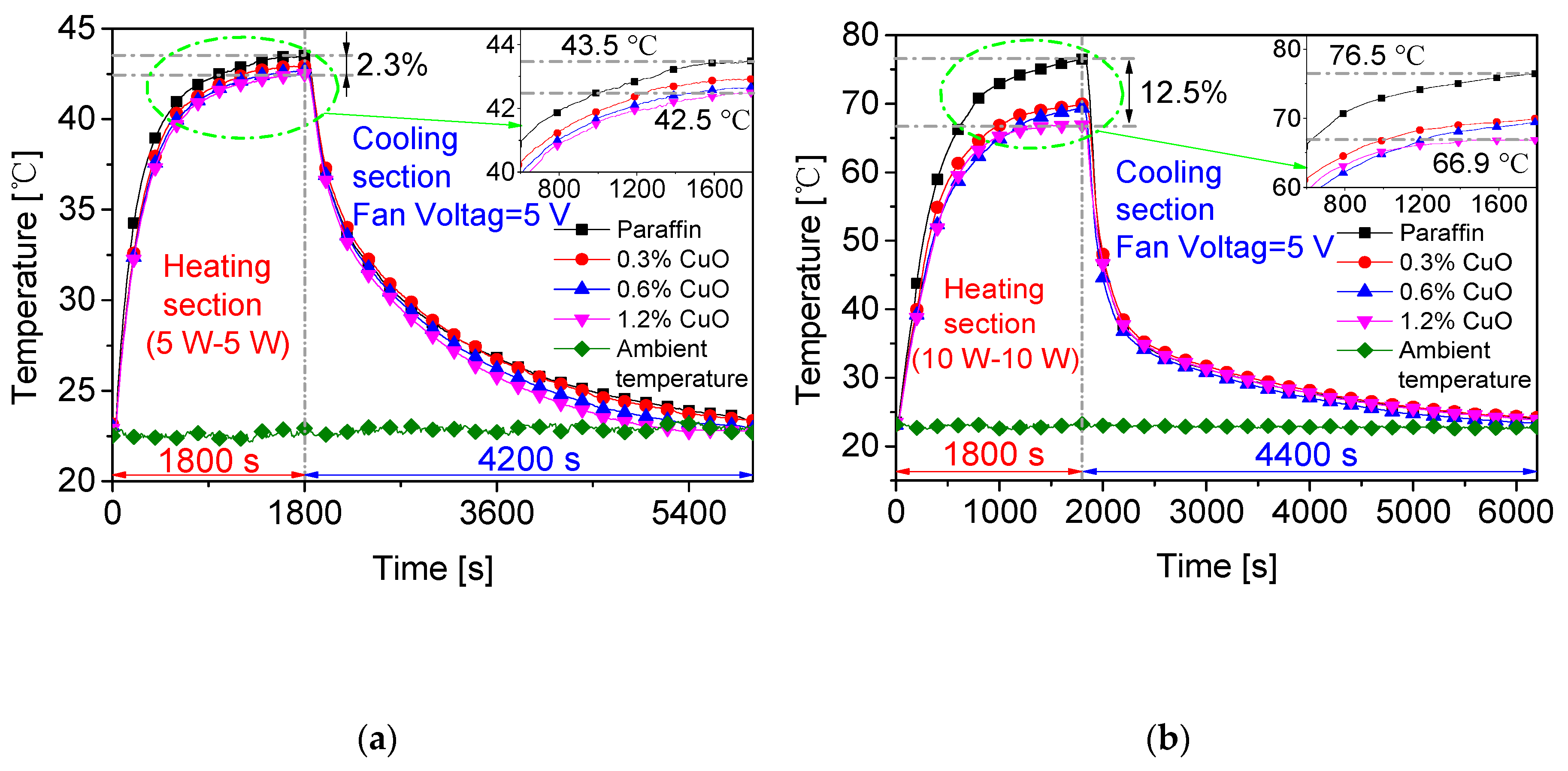
Paraffin is mixed with the nanoparticle CuO to improve the heat-transfer performance of the base material. As shown in Figure 4a, it is found that using 1.2% CuO/paraffin as the phase-change energy-storage material has the best cooling effectiveness, and the evaporator temperature is reduced by 2.3% compared with the case with paraffin wax. For the heat sources 1 and 2 under the same power of 10 W, the evaporator temperature of the heat pipe with 1.2% CuO/paraffin is 12.5% lower than that with the pure paraffin, as shown in Figure 4b. It is found that the addition of the nanoparticle CuO improves the heat-transfer characteristics of the heat pipe.
3.3. Analysis of Infrared Temperature Field
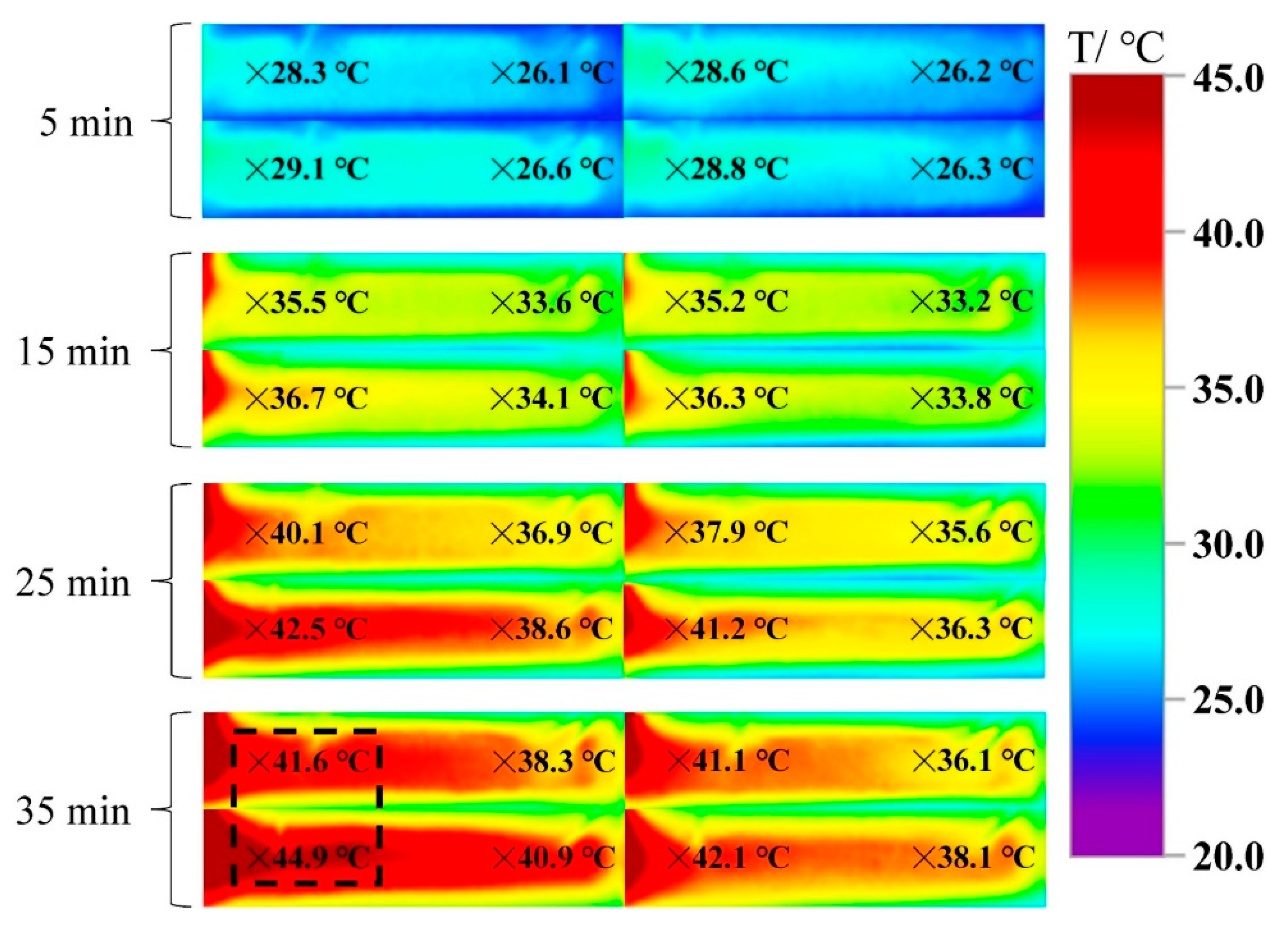
During the charging and discharging processes, when the heating power changes in an electronic component, the heat will be stored in the PCMs first and then released slowly. To simulate the same actual situation, the heat source 1 has alternate powers of 5 and 10 W every 5 min, as listed in Table 3.
During different heating stages at fan voltages of 5 and 10 V, Figure 5 shows the temperature distributions of the pure paraffin and 1.2% CuO/paraffin composites, using an infrared thermal imager (Shenzhen Meikeyi Technology Co., Ltd., Shenzhen, China). It is observed that, during 15 min heating, the temperature distribution of the 1.2% CuO/paraffin composites is somewhat different from that of pure paraffin. When the evaporator section is heated for 25 min, a portion of the pure paraffin at 5 V fan voltage reaches above 40 °C, whereas all the pure paraffin has a temperature below 40 °C at 10 V fan voltage. This result shows that the pure paraffin under 10 V fan voltage has a lower surface temperature field than that under 5 V fan voltage. In addition, during the 35 min heating process, it is easily found that the temperature distribution of the 1.2% CuO/paraffin composites is significantly higher than that of pure paraffin. Under 5 V fan voltage, the maximum temperature difference between 1.2% CuO/paraffin composites and pure paraffin at the same position is 3.3 °C. The results show that, compared with pure paraffin, the addition of the 1.2% CuO nanoparticles can effectively improve the heat dissipation at the evaporator. When the fan runs at low power, more paraffin wax will melt completely. This result indicates that the latent heat of PCMs can be fully utilized to lower the temperature of the evaporator.
4. Conclusions
In a two-heat-source system, under a constant heating power, paraffin wax can effectively reduce the temperature of the evaporator. It is found that, when the power of the heat sources 1 and 2 is 10 W, paraffin wax used as energy storage materials reduces the temperature of the evaporator by 14.4%, compared with the case without paraffin wax.
Because CuO/paraffin nanocomposites can store more heat from the heat sources to avoid affecting the normal operation of the cooling module, the CuO/paraffin nanocomposites are used to weaken temperature fluctuations on the heat sources in this research. When the heating power of the heat sources 1 and 2 is 10 W, the evaporator temperature of the heat pipe with 1.2% CuO/paraffin is 12.5% lower than that with the pure paraffin.
Author Contributions
Methodology, Y.L.; formal analysis, Y.L. and J.W.; investigation, Y.L. and J.W.; writing–original draft preparation, Y.L. and J.W.; writing–review and editing, J.W. and B.S.; funding acquisition, J.W. and L.Y. All authors have read and agreed to the published version of the manuscript.
Funding
This work is supported by the National Natural Science Foundation of China (grant number 51876161) and the Project of Innovation Ability Training for Postgraduate Students of Education Department of Hebei Province (grant number CXZZSS2019012).
Conflicts of Interest
The authors declare no conflict of interest.
References
- Wang, Q.C.; Rao, Z.H.; Huo, Y.T.; Wang, S.F. Thermal performance of phase change material/oscillating heat pipe-based battery thermal management system. Int. J. Therm. Sci. 2016, 102, 9–16. [Google Scholar] [CrossRef]
- Bose, P.; Amirtham, V.A. A review on thermal conductivity enhancement of paraffin wax as latent heat energy storage material. Renew. Sustain. Energy Rev. 2016, 65, 81–100. [Google Scholar] [CrossRef]
- Fan, L.W.; Fang, X.; Wang, X.; Zeng, Y.; Xiao, Y.Q.; Yu, Z.T.; Xu, X.; Hu, Y.C.; Cen, K.F. Effects of various carbon nanofillers on the thermal conductivity and energy storage properties of paraffin-based nanocomposite phase change materials. Appl. Energy 2013, 110, 163–172. [Google Scholar] [CrossRef]
- Wu, X.H.; Wang, C.X.; Wang, Y.L.; Zhu, Y.J. Experimental study of thermo-physical properties and application of paraffin-carbon nanotubes composite phase change materials. Int. J. Heat Mass Transf. 2019, 140, 671–677. [Google Scholar] [CrossRef]
- Babapoor, A.; Karimi, G. Thermal properties measurement and heat storage analysis of paraffin nanoparticles composites phase change material: Comparison and optimization. Appl. Therm. Eng. 2015, 90, 945–951. [Google Scholar] [CrossRef]
- Arshad, A.; Jabbal, M.; Yan, Y.Y. Preparation and characteristics evaluation of mono and hybrid nanoenhanced phase change materials (NePCMs) for thermal management of microelectronics. Energy Convers. Manag. 2020, 205, 112444. [Google Scholar] [CrossRef]
- Li, W.Q.; Wan, H.; Jing, T.T.; Li, Y.B.; Liu, P.J.; He, G.Q.; Qin, F. Microencapsulated phase change material (MEPCM) saturated in metal foam as an efficient hybrid PCM for passive thermal management: A numerical and experimental study. Appl. Therm. Eng. 2019, 146, 413–421. [Google Scholar] [CrossRef]
- Ren, Q.L.; Guo, P.H.; Zhu, J.J. Thermal management of electronic devices using pin-fin based cascade microencapsulated PCM/expanded graphite composite. Int. J. Heat Mass Transf. 2020, 149, 119199. [Google Scholar] [CrossRef]
- Ling, Y.Z.; Zhang, X.S.; Wang, F.; She, X.H. Performance study of phase change materials coupled with threedimensional oscillating heat pipes with different structures for electronic cooling. Renew. Energy 2020, 154, 636–649. [Google Scholar] [CrossRef]
- Yang, X.H.; Tan, S.C.; He, Z.Z.; Liu, J. Finned heat pipe assisted low melting point metal PCM heat sink against extremely high power thermal shock. Energy Convers. Manag. 2018, 160, 467–476. [Google Scholar] [CrossRef]
- Krishna, J.; Kishore, P.S.; Solomon, A.B. Heat pipe with nano enhanced-PCM for electronic cooling application. Exp. Therm. Fluid Sci. 2017, 81, 84–92. [Google Scholar] [CrossRef] [Green Version]
- Yu, K.; Wang, Y.; Li, Y.X.; Baleta, J.; Wang, J.; Sundén, B. Effect of phase change materials on heat dissipation of a multiple heat source system. Open Phys. 2019, 17, 797–807. [Google Scholar] [CrossRef]
- Zhao, J.T.; Qu, J.; Rao, Z.H. Thermal characteristic and analysis of closed loop oscillation heat pipe/phase change material (CLOHP/PCM) coupling module with different working media. Int. J. Heat Mass Transf. 2018, 126, 257–266. [Google Scholar] [CrossRef]
Figure 1.
SEM of the nanoparticle CuO and scheme for composite preparation: (a) CuO nanoparticles and (b) preparation procedure of nanocomposite phase-change materials (PCMs).
Figure 1.
SEM of the nanoparticle CuO and scheme for composite preparation: (a) CuO nanoparticles and (b) preparation procedure of nanocomposite phase-change materials (PCMs).


Figure 2.
Photos of the testing components and experimental system.

Figure 3.
Temperature variations under different heating powers (heat source 1 power–heat source 2 power): (a) 5 W–5 W and (b) 10 W–10 W.
Figure 3.
Temperature variations under different heating powers (heat source 1 power–heat source 2 power): (a) 5 W–5 W and (b) 10 W–10 W.

Figure 4.
Temperature variations on the evaporator with phase-change materials at the heating power of (a) 5 W–5 W and (b) 10 W–10 W.
Figure 4.
Temperature variations on the evaporator with phase-change materials at the heating power of (a) 5 W–5 W and (b) 10 W–10 W.

Figure 5.
Temperature values on the adiabatic sections covered with the pure paraffin (up) and CuO/paraffin (down) under fan voltages 5 V (left) and 10 V (right), using an infrared thermal imager.
Figure 5.
Temperature values on the adiabatic sections covered with the pure paraffin (up) and CuO/paraffin (down) under fan voltages 5 V (left) and 10 V (right), using an infrared thermal imager.


Table 1.
Accuracies of instruments.
| Equipment | Model | Instrument Range | Accuracy |
|---|---|---|---|
| Ultrasonic oscillator | SK1200H-J | – | – |
| Electronic balance | FA2004B | 0~200 g | ±0.0001 g |
| Thermostatic water bath | HH-1 | 0~99.9 °C | ±1 °C |
| Agilent data collector | 34972A | – | ±0.001 °C |
| Infrared camera | TESTO 885-2 | −20~1200 °C | ±2 °C |
Table 2.
Experimental uncertainties.
| Variable | Maximum Uncertainty |
|---|---|
| Heat input (W) | ±1.5% |
| Heat output (W) | ±3.1% |
| Thermocouple measuring temperature | ±1% |
| PCM heat storage | ±1.7% |
Table 3.
Variable powers at different stages.
| Heating Stage | Heat-Source 1 Power | Heat-Source 2 Power | Time |
|---|---|---|---|
| Heating stage 1 | 5 W | 10 W | 5 min |
| Heating stage 2 | 10 W | 10 W | 5 min |
| Heating stage 3 | 5 W | 10 W | 5 min |
| Heating stage 4 | 10 W | 10 W | 5 min |
| Heating stage 5 | 5 W | 10 W | 5 min |
| Heating stage 6 | 10 W | 10 W | 5 min |
| Heating stage 7 | 5 W | 10 W | 5 min |
© 2020 by the authors. Licensee MDPI, Basel, Switzerland. This article is an open access article distributed under the terms and conditions of the Creative Commons Attribution (CC BY) license (http://creativecommons.org/licenses/by/4.0/).
Share and Cite
MDPI and ACS Style
Li, Y.; Wang, J.; Yang, L.; Sundén, B. Heat-Dissipation Performance of Nanocomposite Phase-Change Materials in a Twin-Heat-Source System. Fluids 2020, 5, 174. https://0-doi-org.brum.beds.ac.uk/10.3390/fluids5040174
AMA Style
Li Y, Wang J, Yang L, Sundén B. Heat-Dissipation Performance of Nanocomposite Phase-Change Materials in a Twin-Heat-Source System. Fluids. 2020; 5(4):174. https://0-doi-org.brum.beds.ac.uk/10.3390/fluids5040174
Chicago/Turabian StyleLi, Yanxin, Jin Wang, Li Yang, and Bengt Sundén. 2020. "Heat-Dissipation Performance of Nanocomposite Phase-Change Materials in a Twin-Heat-Source System" Fluids 5, no. 4: 174. https://0-doi-org.brum.beds.ac.uk/10.3390/fluids5040174