
Natural Convection Melting Influence on the Thermal Resistance of a Brick Partially Filled with Phase Change Material


Laboratory on Convective Heat and Mass Transfer, Tomsk State University, 634050 Tomsk, Russia
*
Author to whom correspondence should be addressed.
Fluids 2021, 6(7), 258; https://0-doi-org.brum.beds.ac.uk/10.3390/fluids6070258
Submission received: 31 May 2021
/
Revised: 9 July 2021
/
Accepted: 12 July 2021
/
Published: 14 July 2021
(This article belongs to the Special Issue Heat Transfer and Fluid Dynamics in Energy Systems)
Abstract
:The constant growth of urban agglomerations with the development of transport networks requires the optimal use of energy and new ways of storing it. Energy efficiency is becoming one of the main challenges of modern engineering. The use of phase change materials in construction expands the possibilities of accumulating and storing solar energy, as well as reducing energy consumption. In this study, we consider the problem of the effect of natural convection on heat transfer in a building block containing a phase change material. Heat transfer, taking into account melting in brick, was analyzed at various temperature differences. The mathematical model was formulated in the form of time-dependent equations of conjugate natural convection using non-dimensional stream function, vorticity, and temperature. The equations describing melting, taking into account natural convection, were solved using the finite difference method. Smoothing parameters were used to describe phase transitions in the material. As a result of calculations, local characteristics of heat and mass transfer at various points in time were obtained, as well as changes in temperature profiles on the side surfaces. It is shown that with a large volume of melt, natural convection increases heat loss by more than 10%.
1. Introduction
Energy efficiency of building structures is one of the paramount tasks of the modern construction industry, due to the constantly growing requirements for reducing heat loss. The use of new building materials and technologies has led to significant savings in the subsequent operation of buildings. The use of phase change materials is one of the new trends in increasing the thermal resistance of building structures. The inclusion of such materials in the outer walls of buildings and attic floors allows a reduction in the impact of external temperature fluctuations during the day due to the latent energy of phase transitions [1,2,3,4,5,6].
Recently, a lot of attention has been paid to the problems of using phase change materials in the design of building structures; quite a lot of numerical studies have been published on this topic, in most of which a one-dimensional problem is solved. This approach does not take into account the effect of melt motion.
Stirring of the melt due to natural convection leads not only to uneven melting, but also contributes to the intensification of heat exchange between the structure and the environment.
Paraffins and fatty acids in a wide range of melting points are used as phase change materials. These organic materials have a high latent energy of melting and are not subject to hypothermia or corrosion. The efficiency of using such materials is determined by many factors, such as the geometry of the structure, the thermophysical properties of the materials, as well as the climatic conditions of operation [7,8]. The melting point of the material should be selected not only in accordance with the daily changes in the ambient temperature, but it is also worth taking into account the seasonal changes in weather conditions and the temperature maintained indoors [2].
The inclusion of PCM in blocks of walls, roofs, and exterior or interior decoration allows the temperature fluctuations in the structure to smooth out [9,10,11]. In a pilot study [12], peak heat flux reductions of 51.3% and 29.7% were obtained for walls facing south and west, respectively. Kosny et al. [10] found a 63% reduction in heat transfer with the inclusion of PCM in roofs and walls.
Memarian et al. [13], using a one-dimensional thermal conductivity model, estimated energy costs for a room with a size of 3.65 m × 4.87 m × 2.4 m, and with a PCM embedded window depending on the melting point. For the Tehran climate, a 15% reduction in energy consumption was obtained with the inclusion of a PCM with a melting point of 29 degrees in the design. A reduction in temperatures under extreme heat loads for multi-PCM construction was evaluated in [14]. There was a greater cooling effect in the roof than in the walls. Temperature fluctuations decreased to 46% in July. In addition, there was a 6% decrease in peak maximum temperatures in July and a 24% increase in minimum temperatures in October. The use of phase change materials in the Latvian climate showed a decrease in peak temperatures by 3–4 degrees [15].
In the study [16], a one-dimensional problem of thermal conductivity in a multilayer wall with a PCM layer with a melting point of 29 degrees was considered. It was shown that the location of the material on the outside of the wall has the greatest effect on the intensity of cooling, while the reduction in energy losses can reach 13.4%.
Another way to incorporate PCM into a design is to make PCM embedded bricks [9,17,18,19]. The most common construction includes a load-bearing railing and an outer layer of insulation. The rest of the layers, including decorative finishes for heat loss calculations, can be disregarded.
In the roof structure, where the highest heat transfer and absorption of solar radiation are usually observed, the phase change material restrains the temperature head and absorbs a large amount of energy during the day [11,20] in its structure, which is a layer of material with a changed phase state. Bhamare et al. [20] analyzed the effect of the slope angle of the PCM layer in a concrete roof from 0° to 4°. It has been shown that a small slope of 2° provides the most efficient thermal management and reduces heat loss by 16% compared to a roof without PCM. Other interesting results on PCM applications can be found in [21,22,23].
The purpose of this study is to evaluate the contribution of natural convection to the thermal performance of a structure with PCM inclusions, and also to determine under what parameters the hydrodynamics in the melt can be neglected. As a result, the effect of convective mixing of the melt on the thermal resistance of the structure was estimated, taking into account unsteady thermal external conditions at various Rayleigh numbers. A rectangular brick block with rectangular inserts filled with phase change material was considered as a model. The brick was heated from the left wall by air convection.
2. Materials and Methods
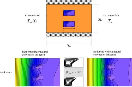
A rectangular brick with inserts of phase change material was considered (Figure 1). The condition of thermal insulation was established on the horizontal walls. On vertical walls, the conditions of air convective heat transfer with constant heat transfer coefficients were considered. From the side of the left wall the air temperature changed according to the harmonic law Tout(t) = T0 + ∆T·sin(2πt/P)) and to the right of the region the air had a constant temperature Tin. At the initial moment of time, the material was in a solid state. When the region was heated, a melt was formed in the cavities, the movement of which is considered to be laminar. Buoyancy is described using the Boussinesq approximation.
Energy transfer inside a brick block is described by the heat conduction equation:
To describe the heat and mass transfer inside a cavity filled with paraffin, the equations of natural convection taking into account melting for the melt and the equation of thermal conductivity for solid non-molten material are used.
The energy equations for PCM are written in an enthalpy formulation. The enthalpy function takes into account the latent energy of melting and depends on temperature as follows:
To make the Equations (1)–(6) dimensionless, the following relations were used:
As a result, the following equations of natural convection in non-primitive stream function and vorticity variables were obtained:
The enthalpy at the boundary of the phase transition has a discontinuity by an amount equal to the latent heat. To pass to a unified energy equation in the solid and liquid phases, the smoothing function φ [24] was used:
Here, η is the smoothing parameter and is equal to 0.01.
The auxiliary functions ξ(φ) and ζ(φ) describe a smooth transition of the thermophysical properties of the material at the interface.
The energy equation for PCM, taking into account phase transitions and natural convection, takes the form:
Heat transfer inside the block will be described by the equation:
At the time τ = 0, the temperature in the block, including the paraffin inserts, was below the melting point of the material, and since the material was in the solid state, the values of the stream function and vorticity were zero Ψ = 0, Ω = 0. Boundary conditions in the dimensionless form for the presented formulation of the problem were as follows:
- At the boundaries between paraffin and brick:
- 2.
- On the right border:
where ;
- 3.
- On the left border:
where
- 4.
- At the upper and lower boundaries:
The boundary conditions for the Poisson equation for the stream function and the vorticity dispersion equation Ψ = 0 were used for all solid boundaries of the melt region, including the interface.
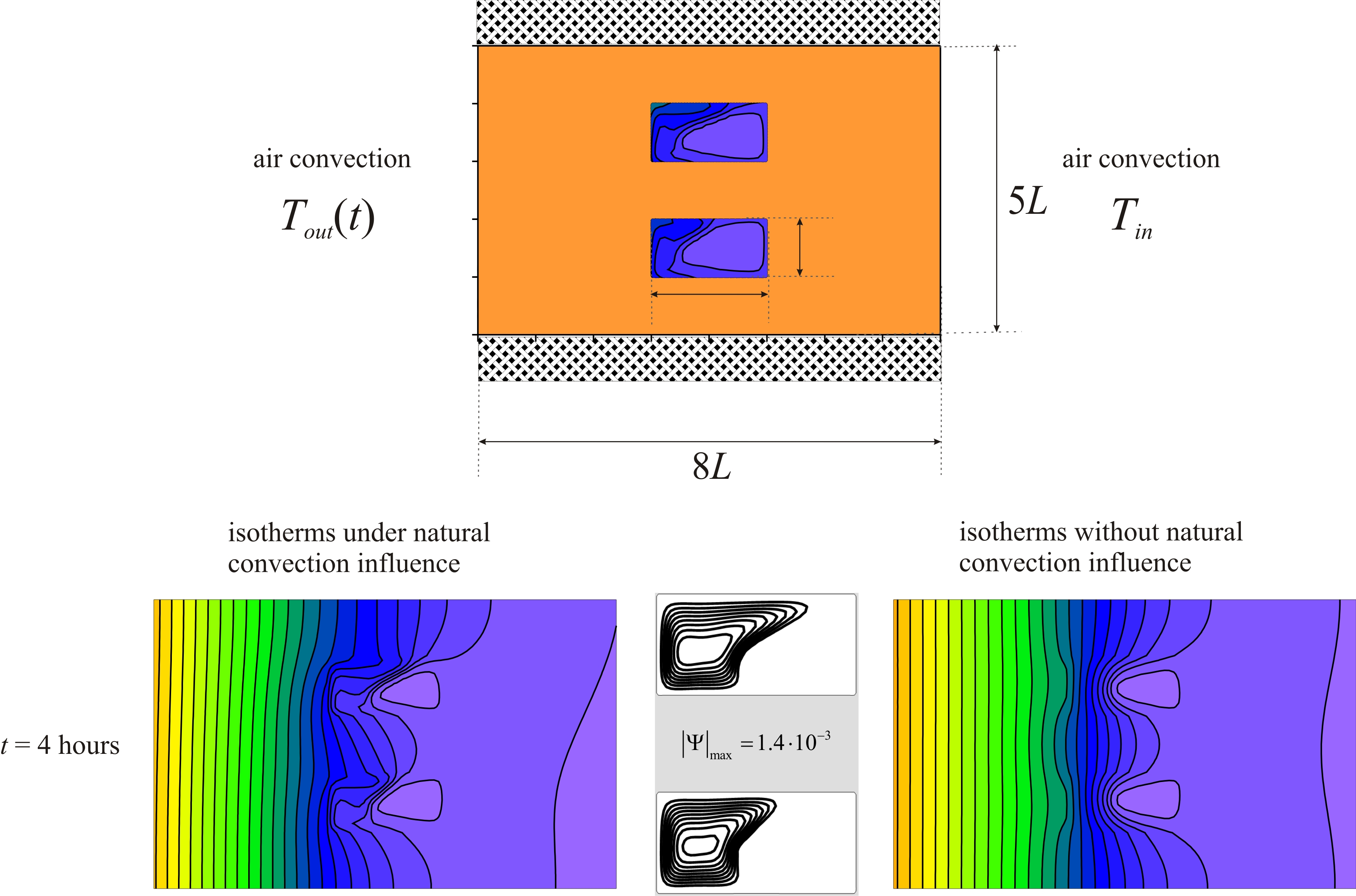
The resulting dimensionless differential equations were solved by the finite difference method on an orthogonal uniform grid. The Poisson equation for the stream function was solved using the successive over-relaxation method. The energy equations for paraffin and brick material, as well as the vorticity dispersion equation were solved using the locally one-dimensional Samarsky scheme. Convective and diffusive terms were approximated by finite differences of a second order accuracy. The numerical model was tested on the experimental problem of melting gallium inside a parallelepiped heated and cooled from vertical opposite walls. Figure 2 shows a comparison of the positions of the melting front at times 2, 6 and 10 and 17 min.
The analysis of the influence of the grid parameters was carried out for three different grids and time steps. Figure 3 shows the isotherms and isolines of the stream function at the time t = 6 h for the cavity height L = 0.02 m, and the temperature difference ∆T = 20°. The convergence of the solution largely depends on the time step. For three grids of 161 × 101 nodes, 281 × 176 nodes, and 401 × 251 nodes, time steps of 0.03, 0.01, and 0.005 were chosen. It can be seen that there is convergence in the grid and the time step, and the solutions on the grids of 281 × 176 and 401 × 251 nodes practically coincide. For greater accuracy, all further calculations were performed for a uniform grid of 401 × 251 nodes.
3. Results and Discussion
As a result of the calculations, the distributions of the temperature fields and the stream function were obtained at different times during heating of the material at different Rayleigh numbers. In dimensional variables, the differences in external temperature from 5 to 20 degrees were considered at L = 0.01 m and L = 0.02 m, which corresponds to the ranges of Rayleigh number 2.27·105 ≤ Ra ≤ 5.9·106 and Stefan number 4.48 ≤ Ste ≤ 14.65. Thermal properties of used materials are presented in Table 1.
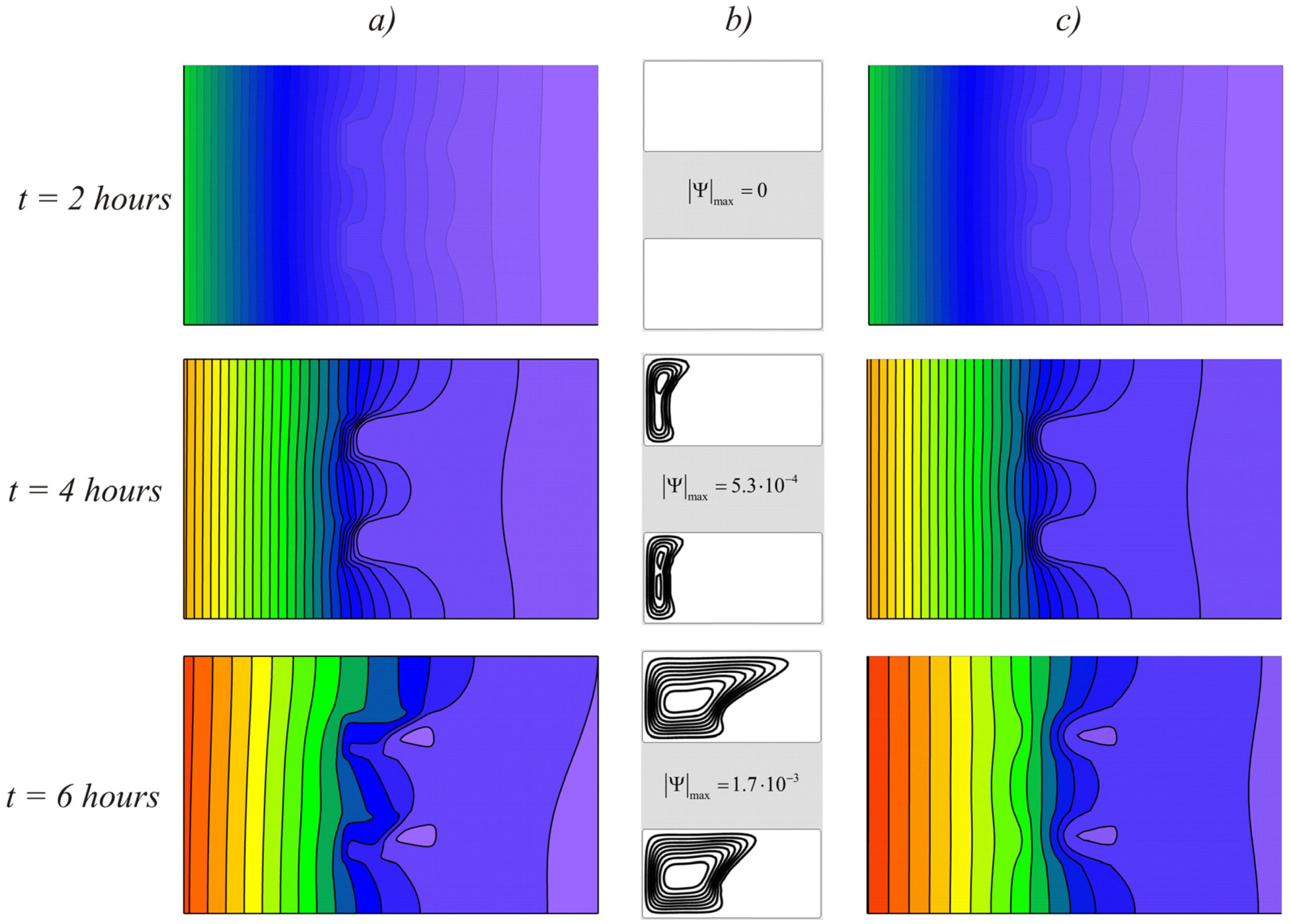
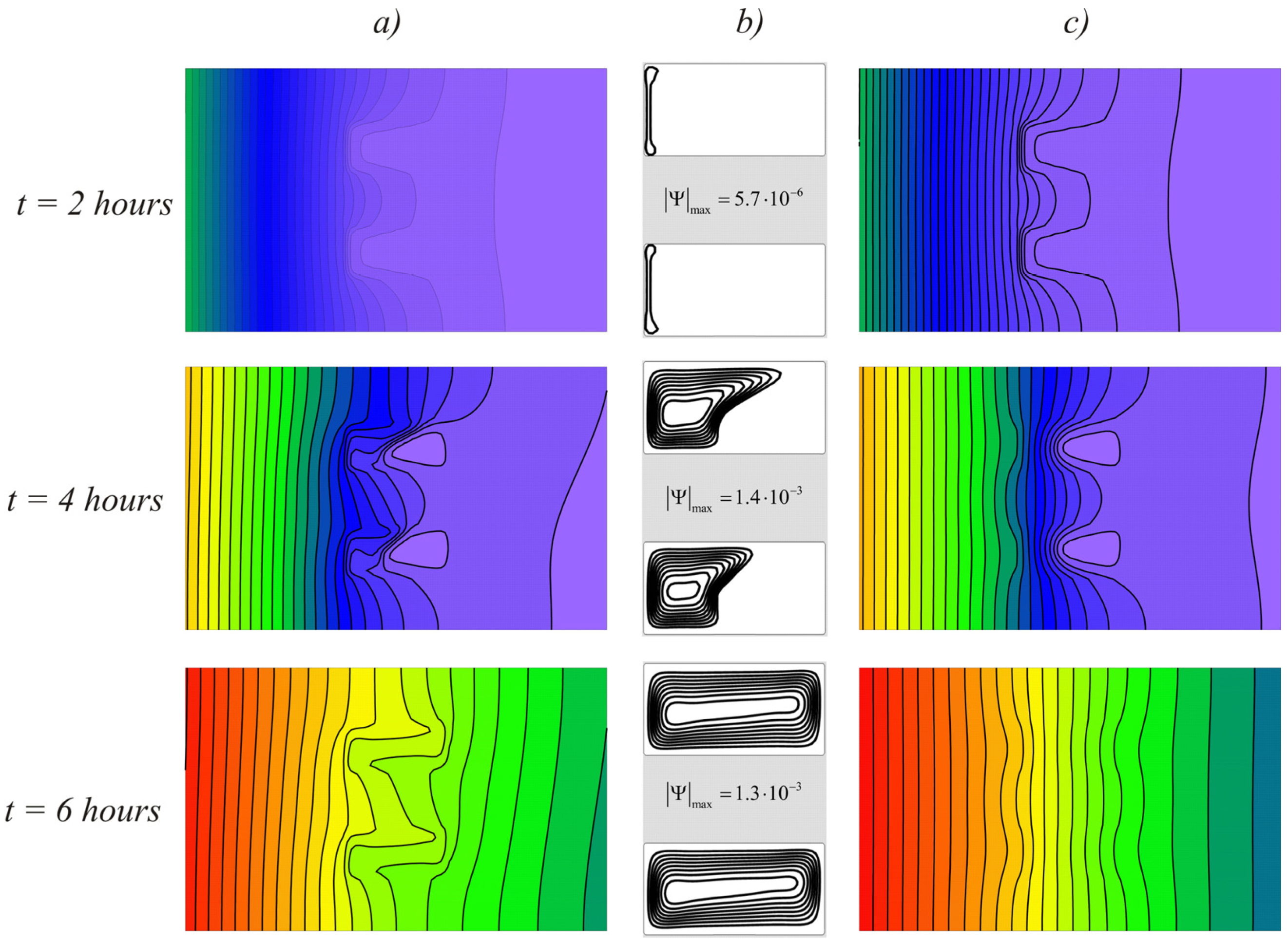
Figure 4 shows the temperature fields (a) and streamlines (b) for the case L = 0.01 and ∆T = 10, taking into account natural convection in the melt and temperature distributions obtained without taking into account natural convection (c) at different times, this case corresponds to the Rayleigh number Ra = 4·105 and the Stephan number Ste = 8.33. After two hours of heating, the material had not yet begun to melt and the temperature distributions for both cases looked the same. At the time instant of 4 h, a weak convective flow appeared in the cavity, rising along the left boundary. Already at this stage, it was clear that the isotherms were condensed to the left of the PCM enclosures, and almost the same temperature was observed on the right side of the brick block. This distribution indicates that the phase change material prevented the passage of heat to the right side of the area, converting it into latent energy. With an increase in the volume of the melt and further heating of the brick, the isotherms in the upper part were shifted to the right wall, as a result of which the upper part of the region was heated more intensively.
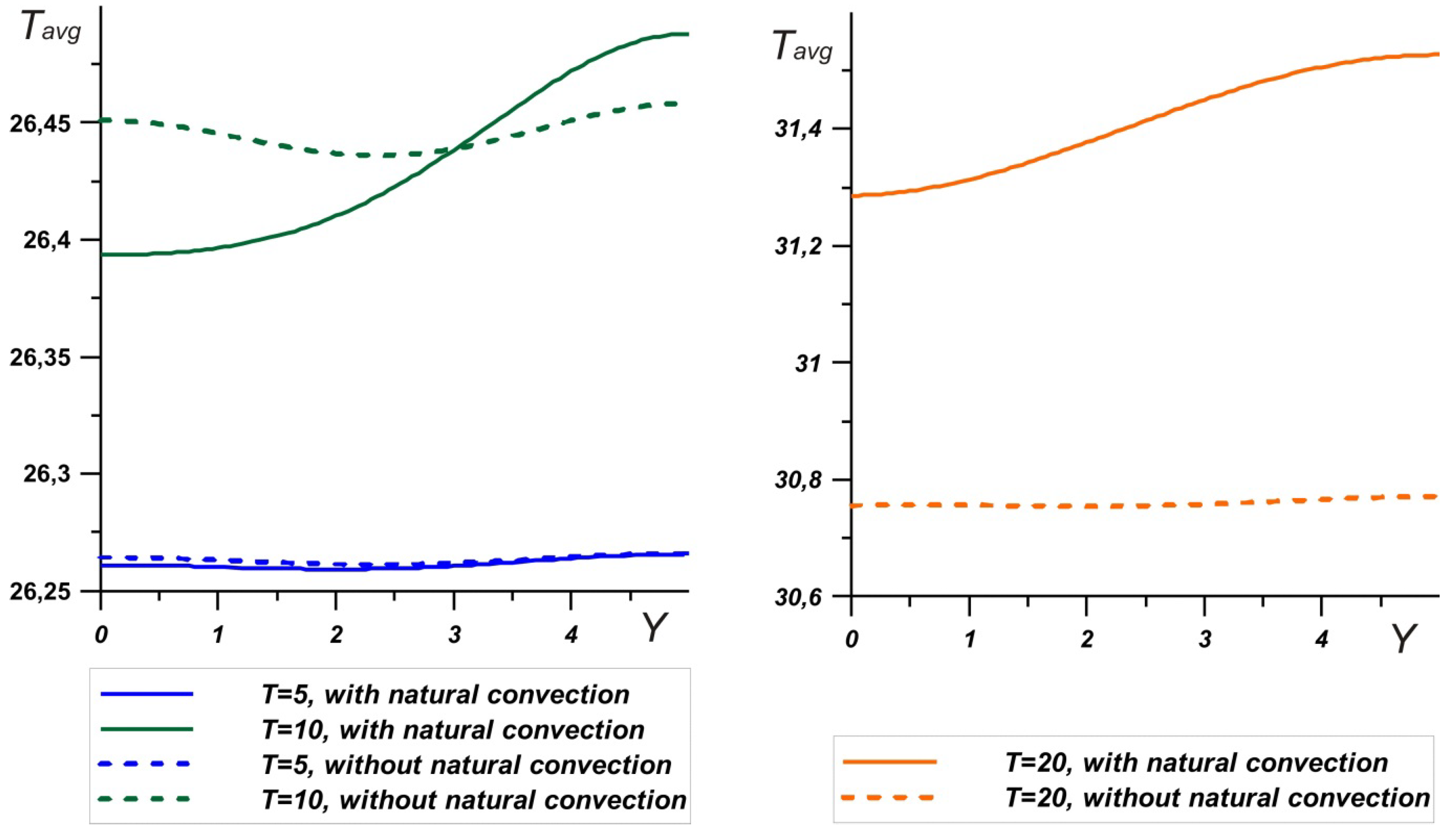
It can also be seen that on the right boundary of the brick, the temperature was slightly higher for the case with natural convection taken into account. Figure 5 shows the temperature profiles on the right wall adjacent to the indoor environment. It can be seen that for ∆T = 10°, as in the case of ∆T = 5°, the temperature on the right wall in cases with natural convection and without convection differed by less than 0.1 degrees, while for a temperature head of ∆T = 20° it exceeded 0.7 degrees. Thus, taking into account the constant heat transfer coefficient on the right wall and the temperature of indoor Tin = 25°, the heat transfer rate increased by more than 10% when the convection effect is taken into account. In this case, as expected, the temperature was higher for the case of natural convection in the melt.
Figure 6 shows the melting process at a temperature difference ∆T = 20° (Ra = 7.4·105 and Ste = 4.48). In this case, the melting process was faster. Along with an increase in the temperature of the external environment, the intensity of convective heat transfer in the region increased with an increase in the melt volume. At the moment of time t = 6 h, the material was already completely melted, and it can be seen that the right wall heated up more intensively for the case taking into account convective heat transfer.
The hydrodynamics are reflected in more detail by the fields of the velocity vector presented in Figure 7. It can be seen that in the process of melting, narrow liquid flows ascend along the vertical wall and descend along the interface; here the highest velocity values are observed. A large heat flux at the interface, caused by the absorption of the energy of the phase transition, enhanced convective heat transfer. When the volume of the solid material completely left and the convective vortex expanded over the entire region, the velocities along the vertical walls decreased, and therefore there was a slight decrease in the maximum value of the stream function .
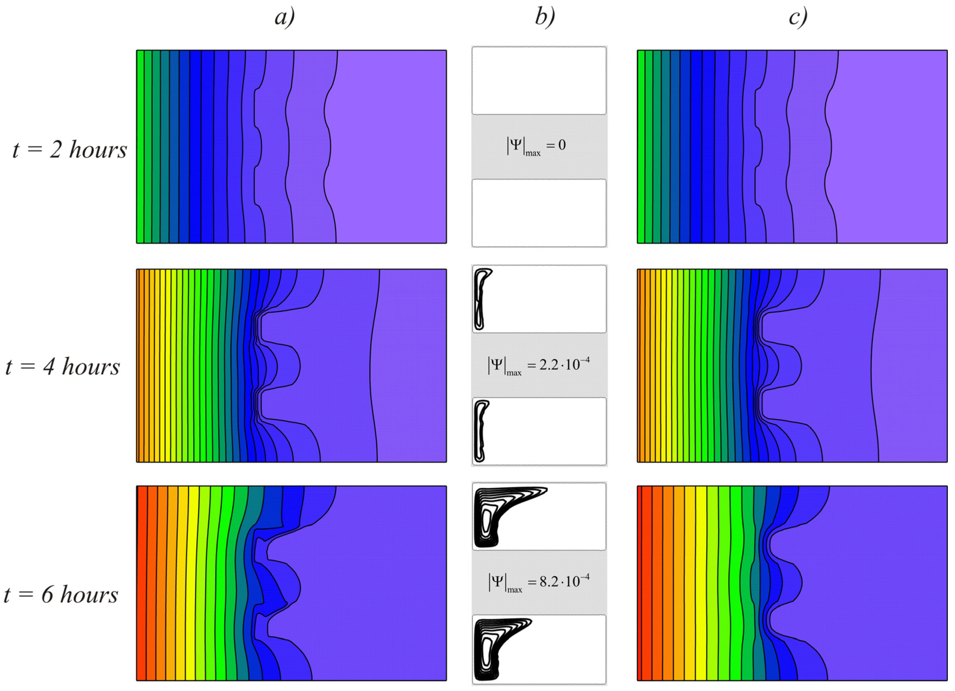
At larger scales of the model, the material did not have time to melt completely, even at high temperature drops (Figure 8). This figure shows the temperature fields and streamlines for the case L = 0.02 m and ∆T = 20° (Ra = 5.9·106 and Ste = 4.48). As in the previous cases, the temperature fields were the same at the initial stages of melting. Since the thermal conductivity of the RT25 was lower than in the brick, the heat was distributed unevenly and the isotherms were bent. With large volumes of material at the time t = 4 h, a small volume fraction of the material melted, while the differences in the temperature fields were insignificant. After six hours of heating, the melt volume remained insignificant in comparison with the volume of unmelted material and the right part of the brick remained unheated both in the case of natural convection and without it.
At the same time, considering the temperature profiles on the left wall (Figure 9a), it should be noted that natural convection reduced the brick temperature by mixing the melt. In the upper part, the brick, as expected, heated up more, while the temperature of the left wall was 0.3 degrees lower over the entire height during convective heat and mass transfer. Hence, it can be concluded that natural convection makes a significant contribution to the charging process: by enhancing heat exchange with the outdoor, the phase change material absorbs more energy by increasing the temperature difference with the environment. On the other hand, with such a volume of PCM, there was practically no temperature change on the right wall. At ∆T = 10°, the difference did not exceed 0.01 degrees, for ∆T = 20°, and the presence of convective heat transfer reduced the temperature by no more than 0.04 degrees. It should be noted that in this case, the melting point had a greater effect on the heat transfer between the brick and the interior. Thus, even at large temperature drops, stirring the melt did not significantly reduce the temperature at the right boundary, but promoted greater energy absorption.
4. Conclusions
The influence of natural convection and the efficiency of using PCM in brick for cooling building structures were analyzed. The addition of PCM to a structure has been shown to increase its thermal resistance by absorbing a large amount of energy. It is shown that, at small temperature differences from 5 to 10 degrees from the outer side, convective heat transfer has little effect on the temperature of the inner surface. The temperature difference on the surface does not exceed 0.1 degrees. With an increase in temperature by 20 degrees, more intense melting is observed, while the temperature of the inner surface is 0.7 degrees higher than in the case without natural convection. With a large volume of PCM, if the proportion of molten material is not significant, the temperature change on the inner surface does not exceed 0.04 degrees. However, due to the mixing of the melt, the temperature on the outer surface decreases, increasing heat transfer with the environment. Thus, the influence of natural convection manifests itself in the intensification of heat transfer between the ambient and the interior. With sufficient PCM volume, the effect of natural convection can be neglected. However, a small volume of material and high temperatures contribute to the intensification of convective heat transfer in the structure, which can cause heating of the brick in the upper part and increase heat loss by more than 10%.
Author Contributions
Conceptualization, N.S.B. and M.A.S.; methodology, N.S.B.; software, N.S.B.; validation, N.S.B.; investigation, N.S.B. and M.A.S.; writing—original draft preparation, N.S.B. and M.A.S.; writing—review and editing, N.S.B. and M.A.S. Both authors have read and agreed to the published version of the manuscript.
Funding
This work was supported by the Russian Science Foundation (Project No. 19-79-00308).
Data Availability Statement
All necessary data can be found in this paper.
Conflicts of Interest
The authors declare no conflict of interest.
Nomenclature
| Bi | Biot number |
| C | specific heat, J K−1 kg−1 |
| g | gravitational acceleration, m s−2 |
| h | enthalpy, J kg−1 |
| k | thermal conductivity, W K−1m−1 |
| L | cavity height, m |
| LF | fusion energy or latent heat of melting, J kg−1 |
| p | pressure, Pa |
| P | dimensionless half-cycle equivalent to 12 hours in dimensional time |
| Pr | Prandtl number |
| Ra | Rayleigh number |
| Ste | Stefan number |
| t | time, s |
| T | temperature, °K |
| TF | melting temperature |
| u, v | velocity components in Cartesian coordinate along x and y, m s−1 |
| U, V | dimensionless velocity components |
| x, y | Cartesian coordinate, m |
| X, Y | dimensionless Cartesian coordinates |
| Greek symbols | |
| α | thermal diffusivity, m2 s−1 |
| β | coefficient of thermal expansion, K−1 |
| γ | heat transfer coefficient, W K−1 m−2 |
| Θ | dimensionless temperature |
| μ | dynamic viscosity, Pa s |
| ν | kinematic viscosity, m2 s−1 |
| ρ | density, kg·m−3 |
| τ | dimensionless time |
| ψ | stream function, m2 s−1 |
| Ψ | dimensionless stream function |
| ω | vorticity, s−1 |
| Ω | dimensionless vorticity |
| Subscripts | |
| b | brick |
| l | liquid |
| PCM | phase change material |
| s | solid |
References
- Barreneche, C.; Navarro, M.E.; Fernández, A.I.; Cabeza, L.F. Improvement of the thermal inertia of building materials incorporating PCM. Evaluation in the macroscale. Appl. Energy 2013, 109, 428–432. [Google Scholar] [CrossRef]
- Pasupathy, A.; Velraj, R. Effect of double layer phase change material in building roof for year round thermal management. Energy Build. 2008, 40, 193–203. [Google Scholar] [CrossRef]
- Mourid, A.; El Alami, M. Thermal behavior of a building provided with phase-change materials on the roof and exposed to solar radiation. J. Sol. Energy Eng. 2017, 139, 1–10. [Google Scholar] [CrossRef]
- Gounni, A.; El Alami, M. The optimal allocation of the PCM within a composite wall for surface temperature and heat flux reduction: An experimental approach. Appl. Therm. Eng. 2017, 127, 1488–1494. [Google Scholar] [CrossRef]
- Guarino, F.; Dermardiros, V.; Chen, Y.; Rao, J.; Cellura, M.; Mistretta, M. PCM thermal energy storage in buildings: Experimental study and applications. Energy Procedia 2015, 70, 219–228. [Google Scholar] [CrossRef] [Green Version]
- Souayfane, F.; Henry, P.; Fardoun, F.; Achard, P. Energy performance and economic analysis of a TIM-PCM wall under different climates. Energy 2019, 169, 1274–1291. [Google Scholar] [CrossRef]
- Lagou, A.; Kylili, A.; Šadauskiene, J.; Fokaides, P.A. Numerical investigation of phase change materials (PCM) optimal melting properties and position in building elements under diverse conditions. Constr. Build. Mater. 2019, 225, 452–464. [Google Scholar] [CrossRef]
- Evers, A.C.; Medina, M.A.; Fang, Y. Evaluation of the thermal performance of frame walls enhanced with paraffin and hydrated salt phase change materials using a dynamic wall simulator. Build. Environ. 2010, 45, 1762–1768. [Google Scholar] [CrossRef]
- Souci, Y.O.; Houat, S. Numerical study of building materials filled by PCM for thermal energy storage. Silic. Based Compos. Mater. 2018, 70, 123–127. [Google Scholar] [CrossRef]
- Kosny, J.; Miller, W.A.; Yarbrough, D.; Kossecka, E.; Biswas, K. Application of Phase Change Materials and Conventional Thermal Mass for Control of Roof-Generated Cooling Loads. Appl. Sci. 2020, 10, 6875. [Google Scholar] [CrossRef]
- Li, D.; Zheng, Y.; Liu, C.; Wu, G. Numerical analysis on thermal performance of roof contained PCM of a single residential building. Energy Convers. Manag. 2015, 100, 147–156. [Google Scholar] [CrossRef]
- Lee, K.O.; Medina, M.A.; Raith, E.; Sun, X. Assessing the integration of a thin phase change material (PCM) layer in a residential building wall for heat transfer reduction and management. Appl. Energy 2015, 137, 699–706. [Google Scholar] [CrossRef]
- Memarian, S.; Kari, B.M.; Fayaz, R.; Asadi, S. Single and combined phase change materials: Their effect on seasonal transition period. Energy Build. 2018, 169, 453–472. [Google Scholar] [CrossRef]
- Berardi, U.; Soudian, S. Experimental investigation of latent heat thermal energy storage using PCMs with different melting temperatures for building retrofit. Energy Build. 2019, 185, 180–195. [Google Scholar] [CrossRef]
- Sinka, M.; Bajare, D.; Jakovics, A.; Ratnieks, J.; Gendelis, S.; Tihana, J. Experimental testing of phase change materials in a warm-summer humid continental climate. Energy Build. 2019, 195, 205–215. [Google Scholar] [CrossRef]
- Saafi, K.; Daouas, N. Energy and cost efficiency of phase change materials integrated in building envelopes under Tunisia Mediterranean climate. Energy 2019, 187, 115987. [Google Scholar] [CrossRef]
- Kant, K.; Shukla, A.; Sharma, A. Heat transfer studies of building brick containing phase change materials. Sol. Energy 2017, 155, 1233–1242. [Google Scholar] [CrossRef]
- Saxena, R.; Rakshit, D.; Kaushik, S.C. Experimental assessment of Phase Change Material (PCM) embedded bricks for passive conditioning in buildings. Renew. Energy 2019, 149, 587–599. [Google Scholar] [CrossRef]
- Saxena, R.; Rakshit, D.; Kaushik, S.C. Phase change material (PCM) incorporated bricks for energy conservation in composite climate: A sustainable building solution. Sol. Energy 2019, 183, 276–284. [Google Scholar] [CrossRef]
- Bhamare, D.K.; Rathod, M.K.; Banerjee, J. Numerical model for evaluating thermal performance of residential building roof integrated with inclined phase change material (PCM) layer. Build. Eng. 2020, 28, 101018. [Google Scholar] [CrossRef]
- Talebizadehsardari, P.; Mahdi, J.M.; Mohammed, H.I.; Moghimi, M.A.; Eisapour, A.H.; Ghalambaz, M. Consecutive charging and discharging of a PCM-based plate heat exchanger with zigzag configuration. Appl. Therm. Eng. 2021, 193, 116970. [Google Scholar] [CrossRef]
- Zadeh, S.M.H.; Mehryan, S.A.M.; Ghalambaz, M.; Ghodrat, M.; Young, J.; Chamkha, A. Hybrid thermal performance enhancement of a circular latent heat storage system by utilizing partially filled copper foam and Cu/GO nano-additives. Energy 2020, 213, 118761. [Google Scholar] [CrossRef]
- Saleh, H.; Siri, Z.; Ghalambaz, M. Natural convection from a bottom heated of an asymmetrical U-shaped enclosure with nano-encapsulated phase change material. J. Energy Storage 2021, 38, 102538. [Google Scholar] [CrossRef]
- Bondareva, N.S.; Sheremet, M.A. Effect of nano-sized heat transfer enhancers on PCM-based heat sink performance at various heat loads. Nanomaterials 2019, 10, 17. [Google Scholar] [CrossRef] [Green Version]
- Gau, C.; Viskanta, R. Melting and solidification of a pure metal on a vertical wall. J. Heat Transf. 1986, 108, 174–181. [Google Scholar] [CrossRef]
Figure 1.
The considered model.

Figure 2.
Comparison of obtained numerical data (solid line) and experimental data [25].
Figure 2.
Comparison of obtained numerical data (solid line) and experimental data [25].

Figure 3.
Isotherms Θ and streamlines Ψ for L = 0.02 m and ∆T = 20° obtained for different grids: solid black line—161 × 101 nodes, solid red line—281 × 176 nodes, dashed line—401 × 251 nodes.
Figure 3.
Isotherms Θ and streamlines Ψ for L = 0.02 m and ∆T = 20° obtained for different grids: solid black line—161 × 101 nodes, solid red line—281 × 176 nodes, dashed line—401 × 251 nodes.

Figure 4.
Temperature fields (a) and streamlines (b) for the case L = 0.01 and ∆T = 10 taking into account natural convection in the melt and temperature distributions obtained without natural convection (c) at different times.
Figure 4.
Temperature fields (a) and streamlines (b) for the case L = 0.01 and ∆T = 10 taking into account natural convection in the melt and temperature distributions obtained without natural convection (c) at different times.

Figure 5.
Temperature profiles on the right wall at L = 0.01m.

Figure 6.
Temperature fields (a) and streamlines (b) for the case L = 0.01 m and ∆T = 20° taking into account natural convection in the melt and temperature distributions obtained without natural convection (c) at different times.
Figure 6.
Temperature fields (a) and streamlines (b) for the case L = 0.01 m and ∆T = 20° taking into account natural convection in the melt and temperature distributions obtained without natural convection (c) at different times.

Figure 7.
Dimensionless velocity field at times t = 4 h and t = 6 h for the case of L = 0.01 m and ∆T = 20°.
Figure 7.
Dimensionless velocity field at times t = 4 h and t = 6 h for the case of L = 0.01 m and ∆T = 20°.

Figure 8.
Temperature fields (a) and streamlines (b) for the case L = 0.02 m and ∆T = 20° taking into account natural convection in the melt and temperature distributions obtained neglecting natural convection (c) at different times.
Figure 8.
Temperature fields (a) and streamlines (b) for the case L = 0.02 m and ∆T = 20° taking into account natural convection in the melt and temperature distributions obtained neglecting natural convection (c) at different times.

Figure 9.
Temperature profiles on the left wall for ∆T = 20° (a) and on the right wall for ∆T = 10° and ∆T = 20° (b) at L = 0.02 m.
Figure 9.
Temperature profiles on the left wall for ∆T = 20° (a) and on the right wall for ∆T = 10° and ∆T = 20° (b) at L = 0.02 m.


Table 1.
Properties of materials.
| Properties | k, W/(m∙K) | c, J/(kg∙K) | ρ, kg/m3 | μ, Pa∙s | Lf, J/kg | |||
|---|---|---|---|---|---|---|---|---|
| Solid | Liquid | Solid | Liquid | Solid | Liquid | |||
| Brick | 0.7 | 840 | 1600 | |||||
| RT25HC (Tf = 26.6 °C) | 0.19 | 0.18 | 1800 | 2400 | 785 | 749 | 0.00375 | 232,000 |
Publisher’s Note: MDPI stays neutral with regard to jurisdictional claims in published maps and institutional affiliations. |
© 2021 by the authors. Licensee MDPI, Basel, Switzerland. This article is an open access article distributed under the terms and conditions of the Creative Commons Attribution (CC BY) license (https://creativecommons.org/licenses/by/4.0/).
Share and Cite
MDPI and ACS Style
Bondareva, N.S.; Sheremet, M.A. Natural Convection Melting Influence on the Thermal Resistance of a Brick Partially Filled with Phase Change Material. Fluids 2021, 6, 258. https://0-doi-org.brum.beds.ac.uk/10.3390/fluids6070258
AMA Style
Bondareva NS, Sheremet MA. Natural Convection Melting Influence on the Thermal Resistance of a Brick Partially Filled with Phase Change Material. Fluids. 2021; 6(7):258. https://0-doi-org.brum.beds.ac.uk/10.3390/fluids6070258
Chicago/Turabian StyleBondareva, Nadezhda S., and Mikhail A. Sheremet. 2021. "Natural Convection Melting Influence on the Thermal Resistance of a Brick Partially Filled with Phase Change Material" Fluids 6, no. 7: 258. https://0-doi-org.brum.beds.ac.uk/10.3390/fluids6070258