1. Introduction
Manuscript B was written by Leonardo da Vinci between 1487 and 1490 [
1], during his Milanese period. It is preserved in the library of the
Institut de France as a part of the Paris Manuscripts and contains drawings of several subjects, from flying and war machines to centrally planned churches. The architectural drawings contained in the manuscript are very dissimilar rom other coeval architects’ project drawings and differ from the drawings produced by architects illustrating codices and treatises [
2]. In fact, among the centrally planned churches depicted in the manuscript, sixteen buildings were represented by Leonardo using an original technique, a pairing of a plan and a perspective view, instead of the traditional technique made of a plan coupled with an elevation [
3]. Moreover, these churches are characterized by some elements so far not well investigated due to the very small size of the drawings and to the inability of traditional analysis techniques (graphic, calligraphic, historical, etc.) to give an accurate explanation of their aim, of the representation technique used and of subject’s depicted features.
This paper aims to investigate the advantages that 3D parametric modeling can offer to the analysis of these small drawings and to define an objective method for conducting this process. The development of a tailored technique for the analysis of these edifices through their hypothetical reconstruction is particularly useful since it could also be extended to other Renaissance case studies. In fact, the issues that one must consider when dealing with the reconstructive process of the centrally planned churches of Ms. B are a superset of the problems that one usually faces in any similar process dealing with unbuilt architecture documented just by drawings.
The study is part of a fruitful line of research, which, starting from the 1980s, has addressed the issue of formulating reconstructive hypotheses, both in the architectural and archaeological fields, of disappeared or destroyed buildings, sites and cities or only designed, and therefore never built. The archaeologist John D. Wilcock recognized the great potential of the computer-generated reconstructions of historical monuments for use in his field of research back in 1973 [
4]. One of the first scientific digital reconstructions of a historical building comes from archeology, when between 1985 and 1989, Mathrafal, an early medieval castle complex in Wales, Great Britain, destroyed in the 13th Century, was digitally reconstructed [
5]. A milestone in the history of the digital reconstruction of historical architecture with art-historical objects is the project on Cluny III realized by Manfred Koob [
6]. The result was a four-minute film that captured both the exterior and the interior of the church. At the end of the last century, within a wide range of initiatives, we saw the institution of the Cultural Virtual Reality Laboratory (CVRLab) at the University of California in Los Angeles (UCLA), founded by Bernard Frischer and Diane Favro, which lead for example to the production of the extensive project of Rome Reborn [
7,
8]. The use of information technologies showed how they can offer new possibilities for investigation, not only as they allow the modeling of buildings in their entirety and the simulation of environmental or dynamic conditions (i.e., light, materials, etc.), but above all because they allow researchers to investigate the formal and compositional rules that characterize some architecture. Exemplary in this context is the fruitful legacy generated by Stiny and Mitchel’s studies on the grammar of form in the case of the Palladian villas [
9], which gave rise to the strand of the reconstruction as
instauratio suggested by Howard Burns during the year 1990 [
10], and to subsequently arrive at the semantic modeling developed from the end of the last century [
11,
12].
Besides, the development of increasingly refined and sophisticated parametric and procedural modeling systems has given rise, within this broad riverbed, to a specific field of research, which, by exploiting the possibility made available by these design and modeling tools, tries to give responses to the many points of interest that characterize this theme: e.g., the possibility of exploring multiple alternative solutions, as well as allowing the formal study of classical architecture [
13,
14], defining a method for reconstruction in the form of a three-dimensional analysis and construction rules [
15,
16,
17], assuring the transparency of analytical methods and criteria used throughout the reconstructive process, showing the related level of uncertainty obtained, etc. [
18].
Therefore, many reasons, which are now pointed out in detail, make the subject ideal to be studied and classified through a 3D reconstruction. First, the churches depicted in the drawings were never realized, so it is particularly useful to translate them into a 3D form to make them more immediate to understand. In fact, the digital reconstruction of unbuilt architecture constitutes a powerful instrument for the analytical process since it increases our ability to understand the features of the drawings and makes us able to notice more elements [
19]. Three-dimensional models therefore assume the value of a “research method, transfer of knowledge and new forms of memory” [
20], showing a great potential thanks to a profound interpretation of the sources and an extensive understanding of the object obtained, creating a hypothetical reproduction [
21]. On the other hand, the field of hypothetical reconstruction of unbuilt architecture, which was explored through several case studies [
20,
22,
23], has some peculiarities, for instance a possible lack of information for some parts and a varying degree of accuracy in the sources, that should be addressed when trying to define a clear digitization methodology [
20].
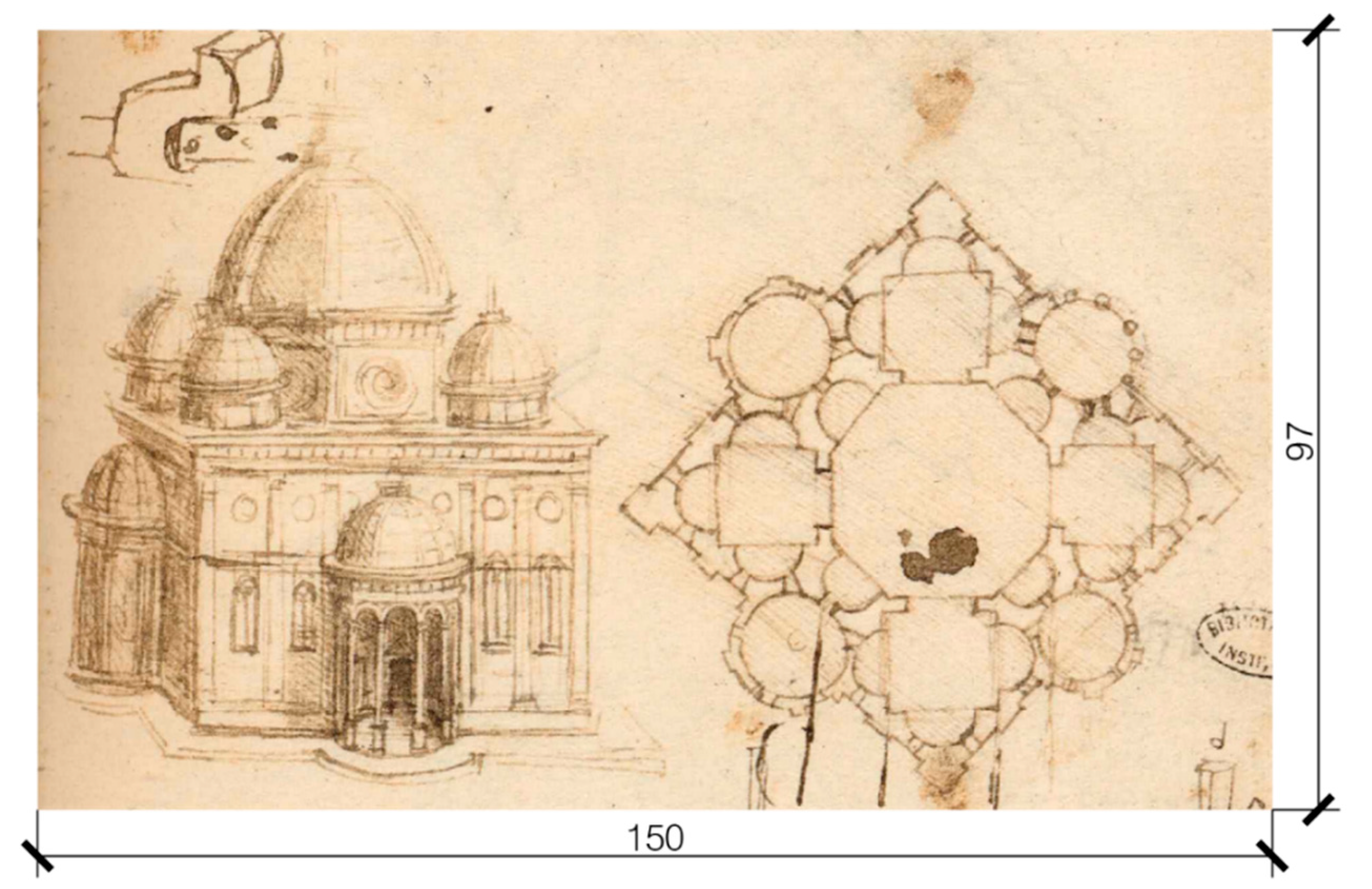
In this case, 3D reconstruction is possible thanks to the depiction technique used by Leonardo, which uses a plan view paired with a perspective view. The latter is a bird’s-eye view that almost resembles a cavalier perspective, so that, if we take a cube as a reference, we have two faces that are parallel to the picture frame and that are consequently in true form [
24]. In this way, Leonardo takes advantage of the capacity of axonometric representation to give immediate information about the volumetric layout, combining it with the plan view to specify the interior distribution of space. This enables us to measure the plan and the façade of the edifices and to also know the disposition of volumes. In fact, the presence of four axes of symmetry makes it possible to infer the exterior characteristics of all the façades of the buildings. Of course, the limited size of the drawings just gives us information regarding the overall dimension and the relative proportional ratios of the architectural elements, and not about the detail of architectural orders; therefore, in order to proceed in a rigorous way, we decided to model the building through essential shapes without specifying them in a detailed way.
Moreover, the two kinds of representation used by Leonardo give enough information regarding the exterior of the buildings but require us to make hypotheses regarding the interiors. In fact, this representational approach entails a lack of information regarding the interior development of the elements in height. These uncertainties imply the need to make multiple assumptions about the interior spaces of the churches. Thus, to maintain a rigorous approach, it is necessary to use coeval or related architectural references as examples. This necessity derives also from another important feature of the drawings that we anticipated: their sizes are extremely limited, since they are contained in folios that measure approximately 16 cm × 23 cm, so they do not contain any architectural detail. Moreover, the churches’ drawings are not accompanied by any information regarding their dimension and scale. To overcome this difficulty, it was necessary to find some elements that could give hints about the extension of the building. Doors and windows are useful to achieve this goal, since it is possible to refer to their usual dimension in coeval edifices and infer an approximate range of dimensions. This value was then used to infer an extension of the building that could give to all the openings a plausible width and height. The production of multiple possible models from fragmentary pieces of information constitutes a core topic in digital heritage research [
21], making this case study particularly useful to understand the casuistry of sources that need to be considered.
Another feature emerging when considering the whole corpus of drawings is that a set of recurring compositive rules is clearly visible in it. In fact, the churches’ layouts have several common elements, and the corpus appears to be an exploration of all the aggregative possibilities of a given form around a central space, or, as was defined by Francesco Paolo di Teodoro, a “geometric play” [
25]. Moreover, the plans appear to be a variation on the theme of the octagon and octagonal stars [
26]. This opens the possibility of creating a complete classification of the layouts, which was tried in the past by two contributions that will be briefly presented [
27,
28], but most importantly, this makes the architecture particularly suitable for a parametric modeling.
In order to use a parametric modeling method based on Leonardo’s rules and not on the authors’ subjective rules (a typical error in historical reconstruction using 3D techniques), the digital reconstruction starts from an analysis of the aggregative features of the complete set of drawings, aimed at extrapolating all the recurrences. Then, the extracted rules are used to define a script potentially able to automatically model all the possible combinations of shapes following those rules, and therefore also the churches of Manuscript B.
The result of this procedure involves two different levels. First, as will be presented in
Section 2, the parametric modeling becomes a means for extracting and reasoning on the geometrical variations and aggregative rules behind the whole
corpus. A similar approach, aimed at studying the possible parametric variations of Palladio’s Villa
La Rotonda, was carried out in the past [
13]. The aggregative study, other than a goal, is also useful to take advantage of all the recurrences between the churches in the 3D modeling process. Starting from it, we will define a system for the classification of the churches, based on the combination of volumetric elements around a central, octagonal space. The churches’ layouts, in fact, share a common taste for the combination of elements, almost like a geometric play. This makes it possible to use the results of the aggregative study as the theoretical basis for the definition of a script for the first stage in the three-dimensional modeling. The nature of the layouts, in fact, is ideal for a parametric and procedural study, which could potentially resemble all the churches starting from the same rules. This step was achieved using Grasshopper, a visual programming language for Rhino, and customizing some components through GhPython.
Then, in
Section 3, the churches are considered one by one: first, the drawings will be analyzed in their proportions, deconstructing the plan view in its components to define a possibility for the geometric process behind its creation. A relation between the geometric elements in plan and elevation will be searched in the related bird’s-eye views. Then, this information will be used to set specific values of height and width in the 3D parametric model. In many cases, the presence of inconsistencies between plan and perspective views will require us to make multiple hypotheses. Then, the 3D parametric model becomes the means to make explicit the multiple possibilities for the drawings’ interpretation and the inconsistencies, which the digital representation process well clarifies and shows. As was anticipated, when dealing with the churches one by one, the absence of an interior view, the small dimension of the drawings and the absence of a dimensional scale require us to also make hypotheses about certain elements to complete the digitization. Therefore, we previously conducted a thorough analysis of the historical context of the manuscript to identify the architectural examples that could be used as references for the assumptions that have to be made for the architectural details, for the interiors and for the building’s dimension.
Finally, the obtained results are described and discussed.
2. Analysis and Parametric Modeling of the Corpus of Drawings as a Whole
In this section, the first part of the method, the one that considers the whole corpus of drawings, is described in its phases.
First, the aggregative rules behind the churches’ designs are extrapolated, considering the attempts made in the past in this direction. Those aggregative rules will be used to classify the churches’ layouts. In order to do so, every feature is catalogued as a variable that is defined by a certain value so that the design of every church can be defined by the entirety of them and vice versa. In fact, the result of this process will be a classification code made up by all the values characterizing the variables.
Second, this identification code is used as a base for the creation of a Grasshopper script that embeds the possibilities of each variable. This script is able to create basic 3D models for all the churches through procedural modelling, since the values of the variables involve a precise set of geometric operations.
2.1. A Proposal for a New Classification Method Based on an Identification Code
The churches of Ms. B are based on a common set of aggregative and dimensional rules. However, defining those rules uniquely is not easy, as the classification of the elements of the buildings can be done according to different points of view. In fact, different authors proposed different classifications based on their idea about the final purpose of Leonardo’s drawings in Ms. B and the kind of approach—planimetric or volumetric—they carry out in the analysis of the drawings.
Among the various studies that considered the churches of Ms. B, e.g., the ones made by Ludwig H. Heydenreich [
29], Luigi Firpo [
30] and Carlo Pedretti [
31], which are certainly useful to analyze Leonardo’s
ouvre, we focus here on the works developed by Jean Paul Richter [
27] and Jean Guillaume [
28], who analyzed the churches through their classification, collecting in a schematic way their features. These classification methods are particularly useful to understand what are the core elements that define the churches layouts, and then become the starting point for the development of a new proposal.
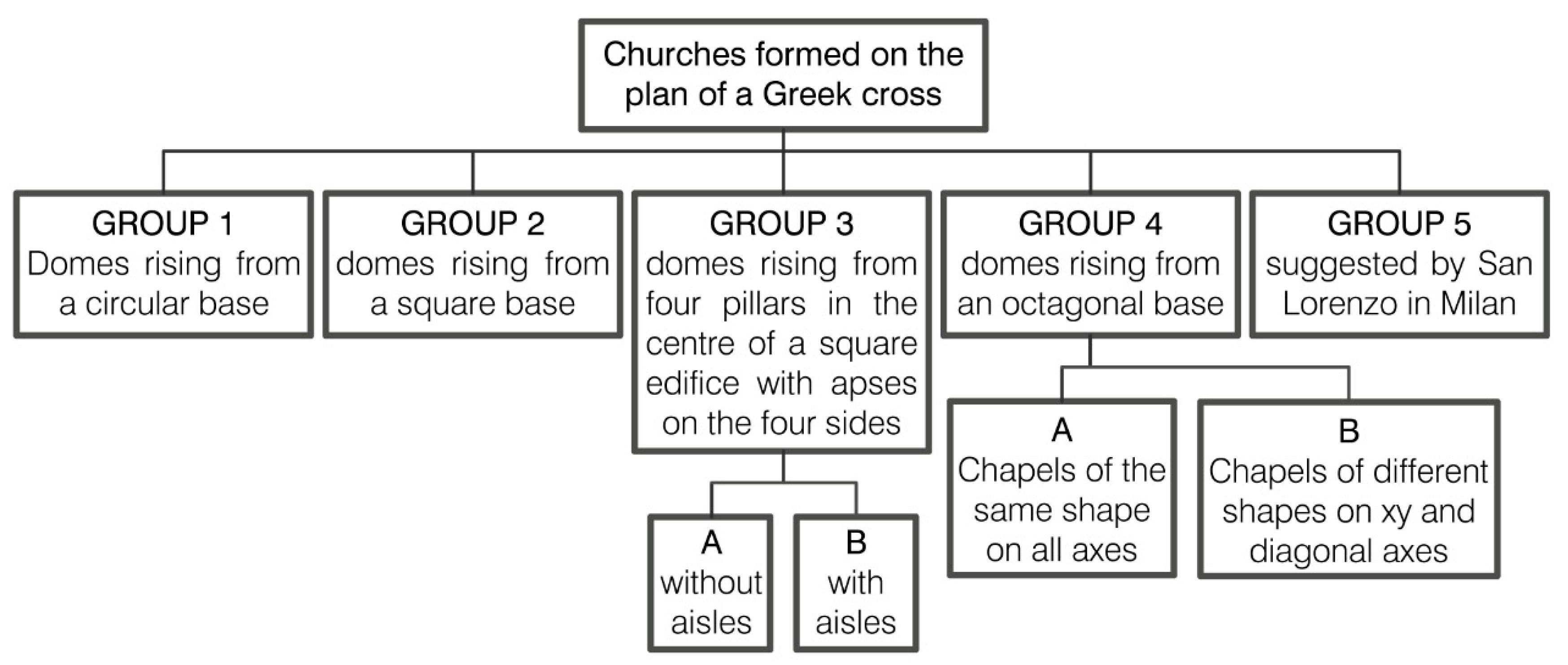
The classification made by Richter [
27] is based on the theory that the drawings of churches were aimed at the realization of a treatise on domes and do not refer to the construction of any building. For this reason, his study is focused on the planimetric classification of the connection between domes and the remaining part of the construction, rather than the aggregative rules behind the composition of the churches (
Figure 1). In his work, J.P. Richter did not pair plan and perspective views, considering them as separate designs. The churches inserted in the various groups then are taken both from plan and perspective views, so that, in case of inconsistency between them, two drawings referred to the same building could be classified into different groups. Moreover, in this study, the author considered the sacred edifices drawn by Leonardo in his entire production, and not only the ones depicted in Ms. B. Some of those churches are not centrally planned, so the first division he operated was between churches “formed on the plan of a Greek cross” and churches coming from longitudinal plan schemes. According to our aims, only the first macro-group was considered and analyzed, as can be seen in
Figure 1, since it is the only one that involves the churches depicted in Ms. B.
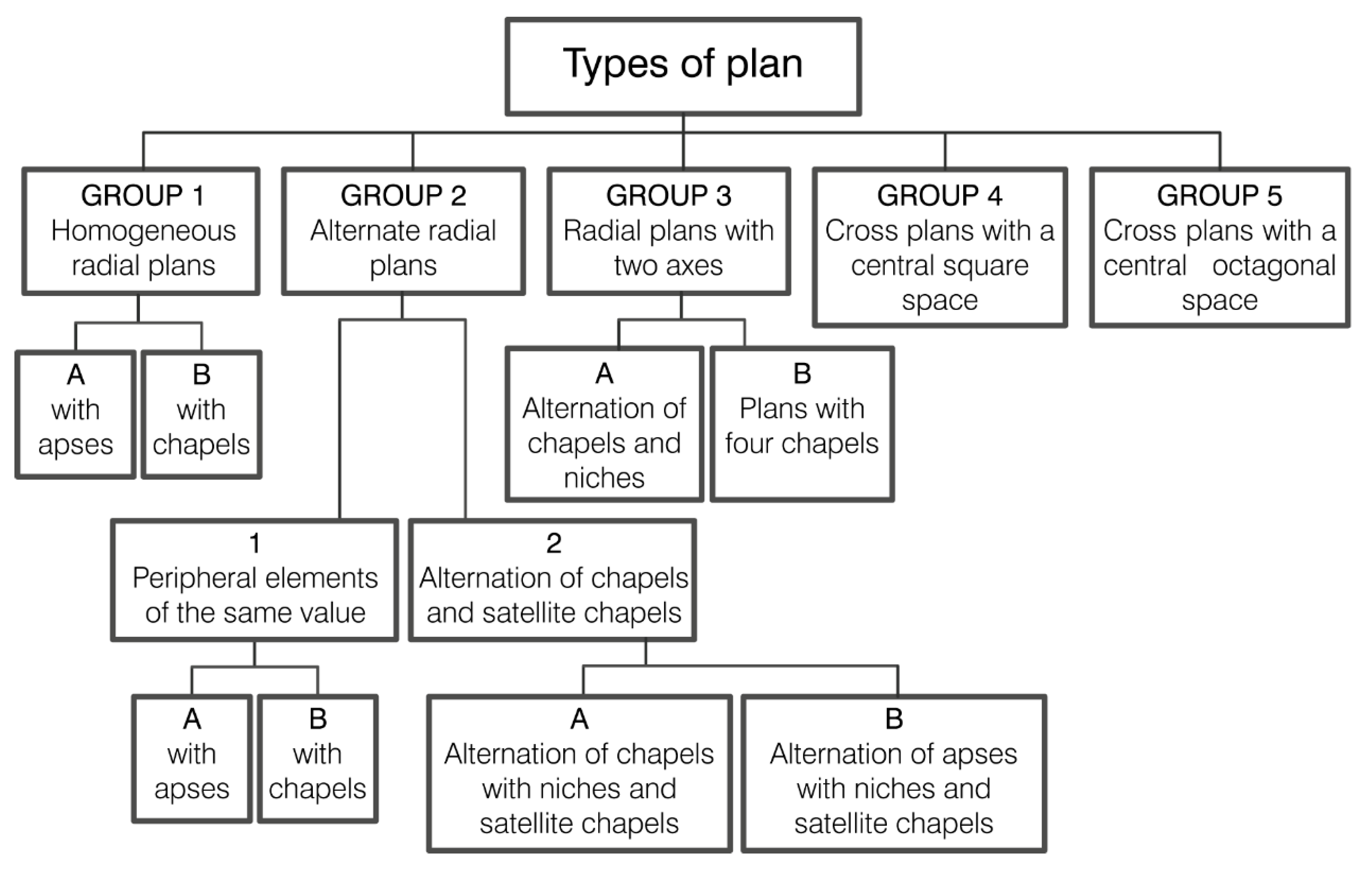
The second classification considered was carried out by Jean Guillaume in 1987 [
28], in the occasion of the exhibition that took place in the
Musée des Beaux-arts of Montreal about Leonardo, architect and engineer. In this case, the point of view of the author was different and focused more on the elements and their aggregations around the central space. Moreover, Guillaume tried, after an analysis in plan (
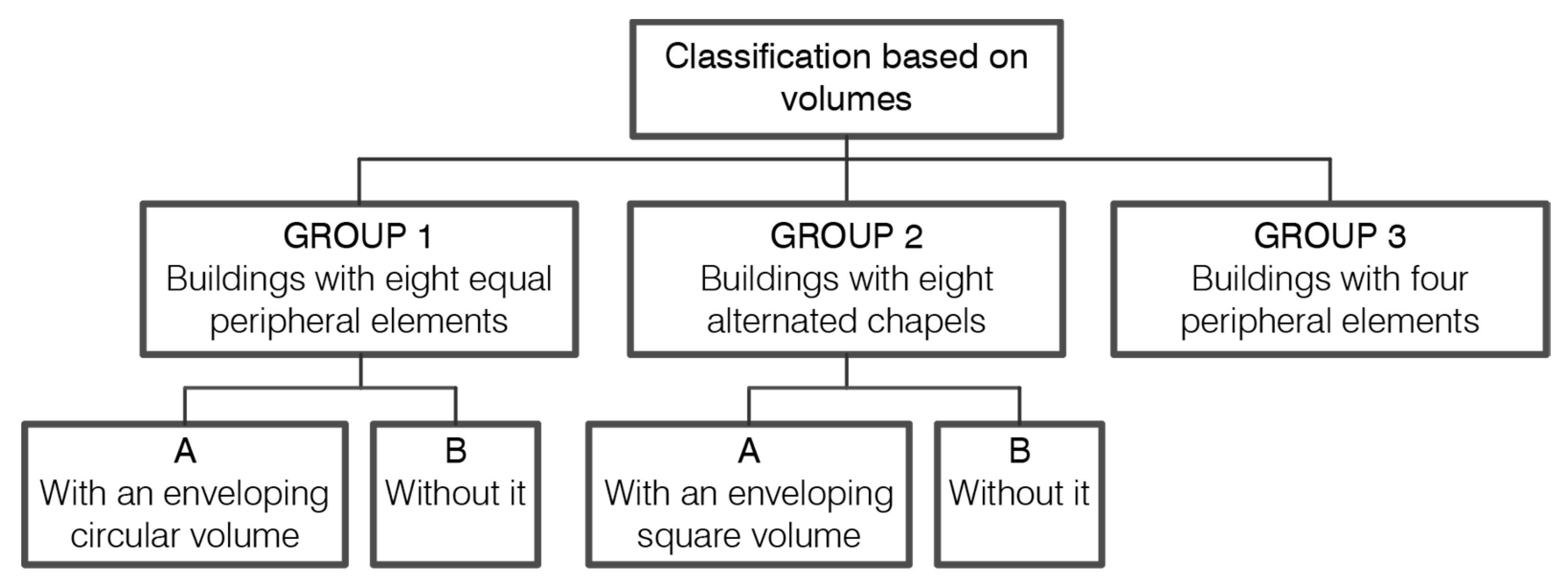
Figure 2), to carry out a volumetric approach that considered the information contained in the perspective views drawn by Leonardo (
Figure 3).
Richter and Guillaume’s works, starting from the same churches, defined two different methods for their classification into groups. As can be seen in the previous schemes, these methods are both based on a subsequential subdivision into groups, which is a hierarchical tree structure. However, even though both of them show several elements of interest, the use of this kind of logical structure to classify this corpus shows some problems due to the limited number of churches in the manuscript combined with the great amount of combinatorial possibilities for their layout. First, there will inevitably be branches containing only one or few elements, and second, the use of this kind of subsequent subdivision, and thus imposing a hierarchy, implies giving more importance to the variation of certain features over others.
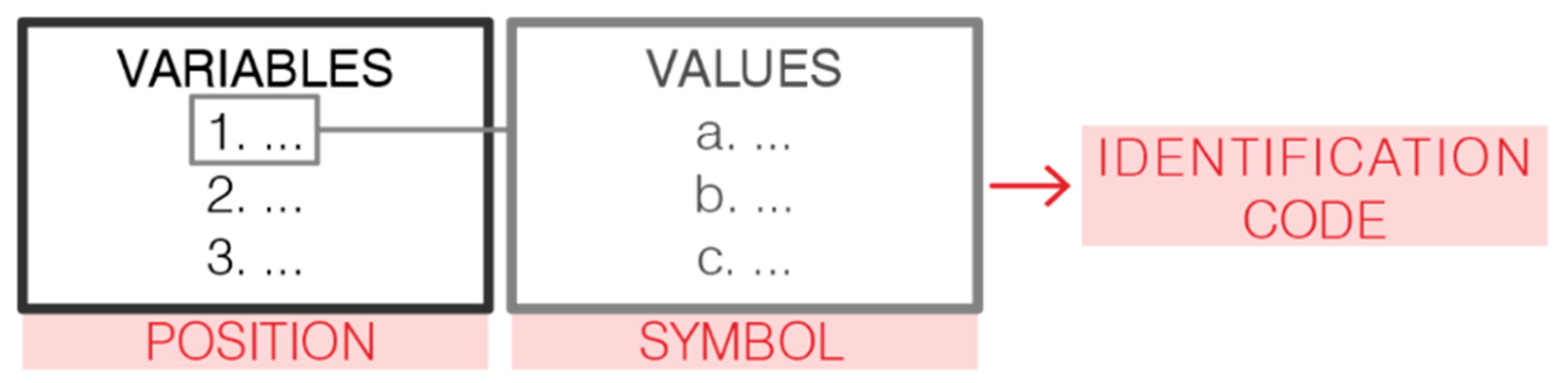
Thus, the idea is to use a classification code, based on the association of values with the defined variables (
Figure 4), rather than grouping the churches into a tree logical structure. The decision to operate in this way comes also from the observation of a characteristic of these layouts: they are, in fact, the recombination of a group of elements around a central space, like in geometric play, and they can thus be studied through a script (at least in a simple way, as we will see). Therefore, the use of a classification code has a further advantage: it notably simplifies the process of the creation of a parametric model able to resemble the churches.
On the other hand, the classifications made by Richter and Guillaume are useful to define what the core characteristics of the churches’ layouts that we consider necessary to fully describe the layout itself are. The hints taken from their works, however, are referred just to the characteristics of the planimetric organization and not the development in height. For instance, the distinction used by both of them between alternate or equal peripheral elements on the XY/diagonal axes (
Figure 1,
Figure 2 and
Figure 3) or the distinction made by Guillaume between the churches with and without an enveloping volumes (
Figure 3) is an example of two important elements that should be featured in our identification code. The features that we consider in our classification method constitute the “variables”, while the possible configurations that a variable can have constitute the “values” (
Figure 4); e.g. considering the previous examples of the elements of their classifications that we should maintain, in the first case (i.e., the distinction between alternate or equal peripheral elements on the XY/diagonal axes), the variables are represented by “shape of the chapels in the XY axes” and “shape of the chapels on the diagonal axes”, while the values that each of them can assume, as we will describe, are many and are represented by all the shapes in the casuistry of the churches in the manuscript. The information about their equality or their difference, thus, is directly inferred from the values assigned to these two variables. Regarding the second example instead (i.e., the distinction between the churches with and without an enveloping volume), the variable is constituted by the “presence of an enveloping volume”, while the possible values that it can assume are two: yes (y) or no (n).
We will now list in detail all the variables that we decided to consider. However, before proceeding with the selection of the variables and with the definition of the identification code, it was necessary to operate a first distinction between two macro-groups of edifices that could not be defined through the same set of variables:
It is interesting to notice that the second group is itself part of a category of chapels that Leonardo uses as peripheral elements for the churches of the first group, so the analysis of the layout of the second group is in fact part of the first one. The difference is that in one case, the four lobed layout is used as an independent system that stands alone as an edifice, while in the other, it becomes the shape of the chapel of a bigger system.
Therefore, the idea is to start from the first group of churches and define a set of variables (in our case, both topological and geometrical) that can define their layout uniquely. Then, for each variable, all the possibilities that Leonardo explores are listed: these are the values of our variable. Afterwards, we decided on an arbitrary order for the variables to be listed and defined a conventional symbol/initial for each value. In this way, our classification system is completely explicated through an identification code.
2.1.1. Churches with a Central Octagonal Space
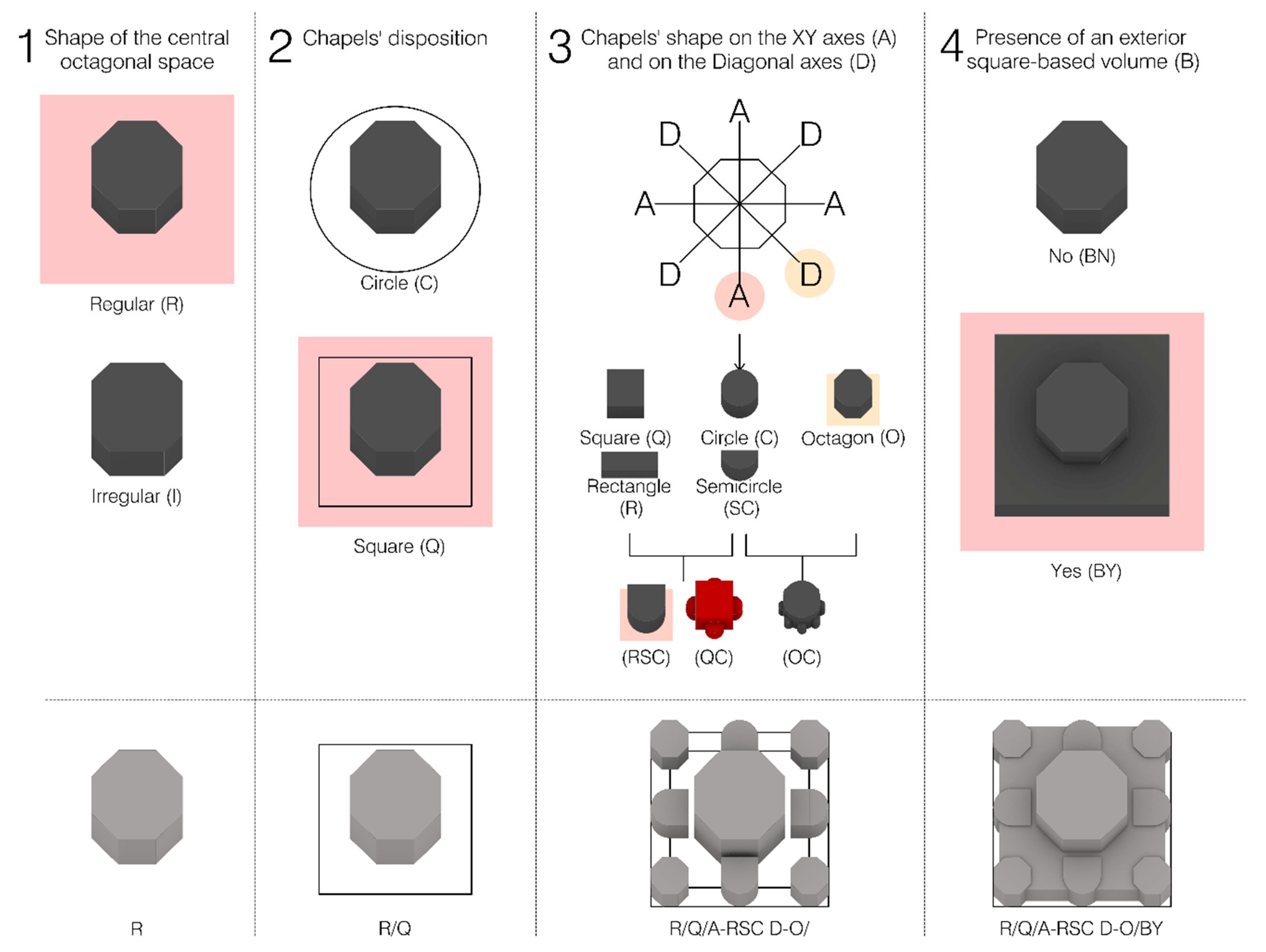
We will now list, in order, the variables and their possibilities. The scheme is presented graphically in
Figure 5.
The first variable is represented by the type of octagonal space, Regular (R) or Irregular (I). Therefore, a church with a central space shaped in plan as a regular octagon will have as the first part of the identification code “R/...”.
The second variable depends on the disposition of chapels or niches around the central space. This disposition can be along a Circle (C) or along a square (Q). Therefore, if the same church of the previous example has the chapels placed along a square, its code will become “R/Q/...”.
The third variable depends on the morphology of the chapels on the XY Axes (A-) and on the Diagonal axes (D-). In this way, we can classify both churches that have chapels of the same shape on all axes and chapels of different shapes on the XY and diagonal axes (i.e., the distinction made by J.P. Richter in Group 4, A and B, that we describe in
Figure 1). This definition also incorporates the distinctions made by J. Guillaume in the five types of plan (
Figure 2) and in the three types of volumes (
Figure 3).
The possible values, thus the shapes that can be assumed, are several and vary from simple ones to ones obtained through a combination of the first. The simple shapes are represented by Octagonal (-O), Circular (-C), Semicircular (-SC), square (-Q) and Rectangular (-R) chapels. From the combination of the previous shapes, we obtain chapels that are made by the Combination of more Circles (-CC), by the combination of a square and Circles (four lobed chapel) (-QC) and by a Rectangular shape combined with a Semicircular one (-RSC). Thus, following the previous example, which can also be seen in
Figure 5, a church with chapels made up of a rectangle combined with a circle on the XY axes and circular chapels on the diagonal ones will be classified as “R/Q/A-RSC D-C/...”. As we anticipated, the four lobed chapel (labeled -QC) will be better explained and subdivided into a further classification (A, B, C) in the next subsection, since Leonardo also used it as an independent edifice in Ms. B, f. 93 v.
The last variable depends on the presence (-Y, Yes) or absence (-N, No) of an exterior square-based volume (B-, Box) that envelops some of the chapels. This distinction is made according to that made by J. Guillaume in his classification based on volumes (
Figure 3). Therefore, the previous example, if characterized by an enveloping volume, will be defined as “R/Q/A-RSC D-C/BY”.
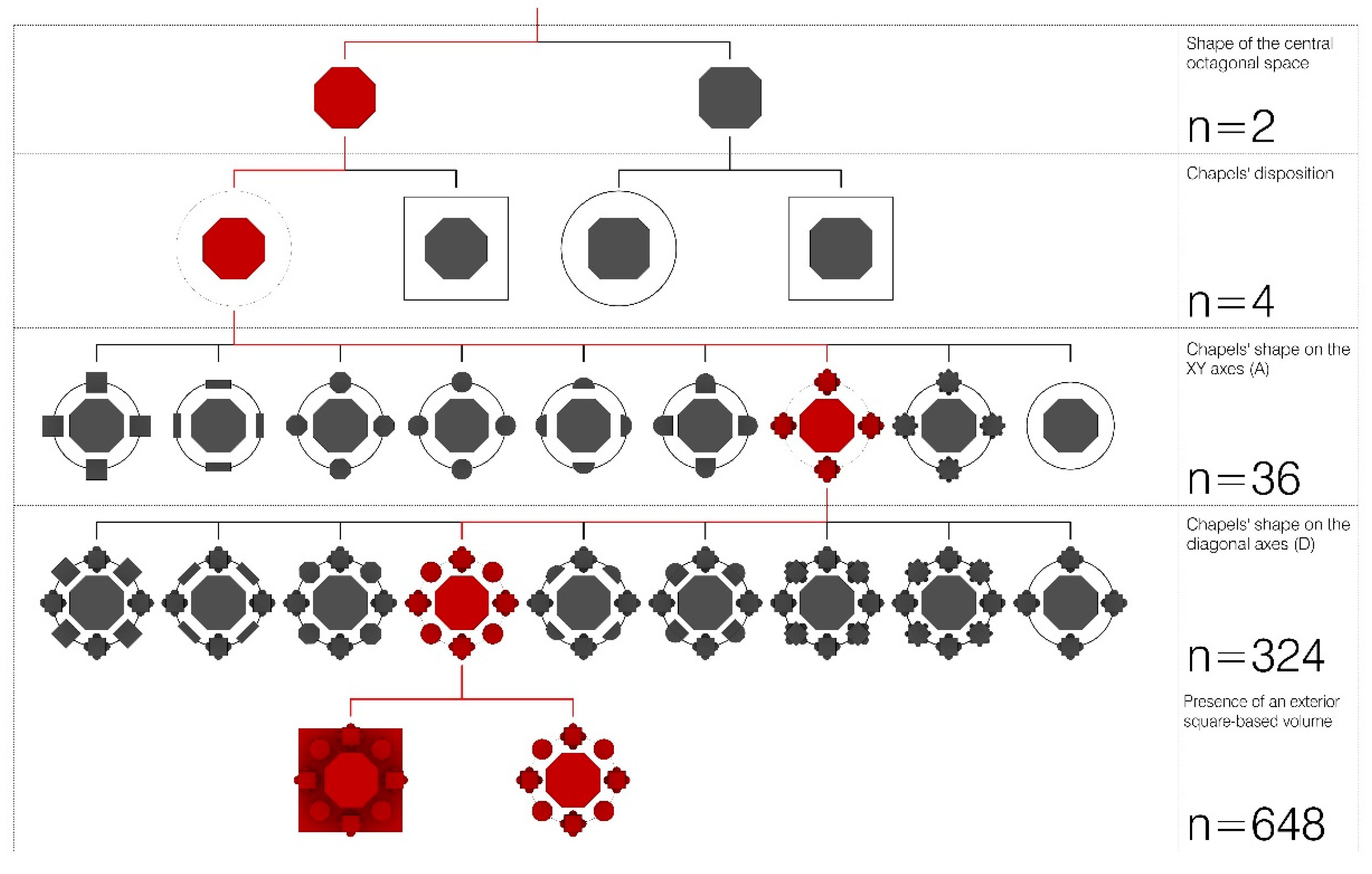
Following this classification method, a total of 648 combinations can be obtained (
Figure 6).
2.1.2. Four Lobed Churches (QC Chapel)
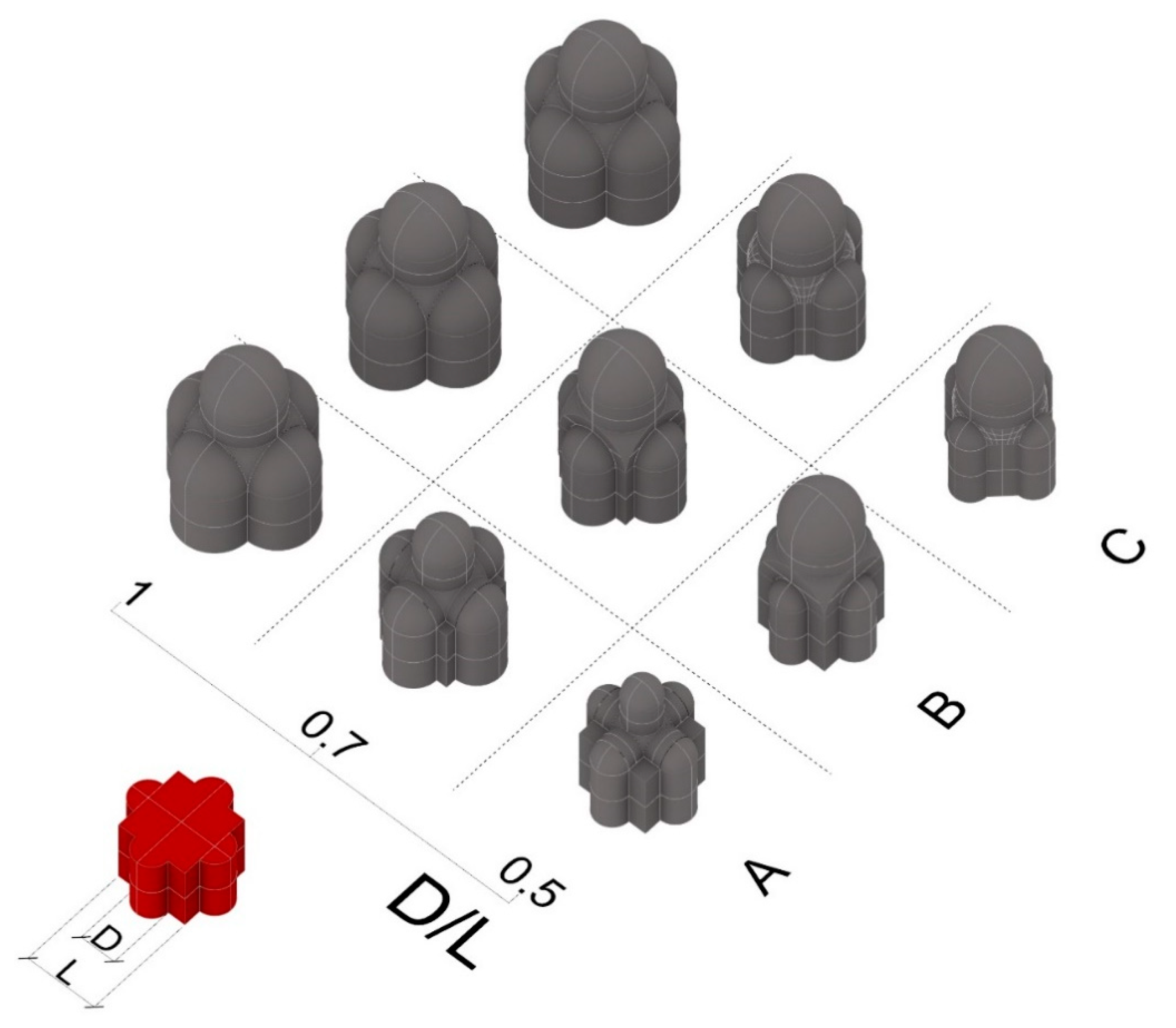
As we have seen, one of the possible shapes for the chapels is the one that comes from the combination of a square with four semicircular apses, named QC in the diagram seen before. Unlike what was done before by Richter and Guillaume, we will try to define a unitary discussion for all the chapels that are four lobed, including the ones that have a dome rising from four pillars, from a square base or from an octagonal one. The idea is to try and include all these three possibilities in the same reasoning and use them in order to develop a unitary parametric model, as we will see in the next section. The elements to consider in our classification are two: the first one is the type (A, B, or C) and the second one the ratio D/L (
Figure 7).
Type A is the one where there are four pillars inside the main square space. There are different possibilities for its realization in detail, since the ceiling in the corners can assume different shapes (groin vault, sailing vault or flat), but this will not be considered at this low Level of Detail (LoD) aggregative analysis (while it will be fundamental in the later stage of three-dimensional reconstruction). The reference here is the Sacello Carolingio (Ninth Century) in the Church of Santa Maria presso San Satiro (1478–1483), in Milan.
Type B instead has the four spherical pendentives leaning on the sides of the square central space and can be referred, for example, to Cappella Pazzi (1441–1478), Santa Maria delle Grazie (1463–1497) in Milan and the Sacrestia Vecchia (1421–1428) in the church of San Lorenzo at Florence.
In Type C, the endpoints of the semicircular apses are joined to form an octagon, and its oblique sides become the basis for the pendentives, as it is done in Cappella Chigi (1512–1656) in Santa Maria del Popolo in Rome.
The ratio D/L gives us information about the Diameter (D) of the apses in comparison with the Length (L) of the sides of the central square space. In this case, we decided to consider a range of values from 0.5 (since we cannot find any example below it in either the references or Ms. B drawings) to one. A value of D/L equal to one is in fact the borderline case, where Type B and Type C coincide, as can be seen in
Figure 6. Nevertheless, the most correct way to consider it would be Type B, since topologically, the central space is a square and not an octagon, and in Type A, the pilasters would end in the corners of the square space, bringing us back to Type B.
2.2. Definition of a Parametric Model Based on the Identification Code
Given all the previous observations, we built a parametric model (embedding some Python code in specific nodes in Grasshopper) that could potentially resemble all the churches of the manuscript, at least as simple volumes. The idea is to turn our classification system into a system of toggles and sliders that can construct the basic shape of the church by just choosing between them. This way, not only could it represent the basic shape of a church of the manuscript by selecting the values identified in its identification code, but it could also represent all the possible church layouts that are defined by the same set of aggregative rules.
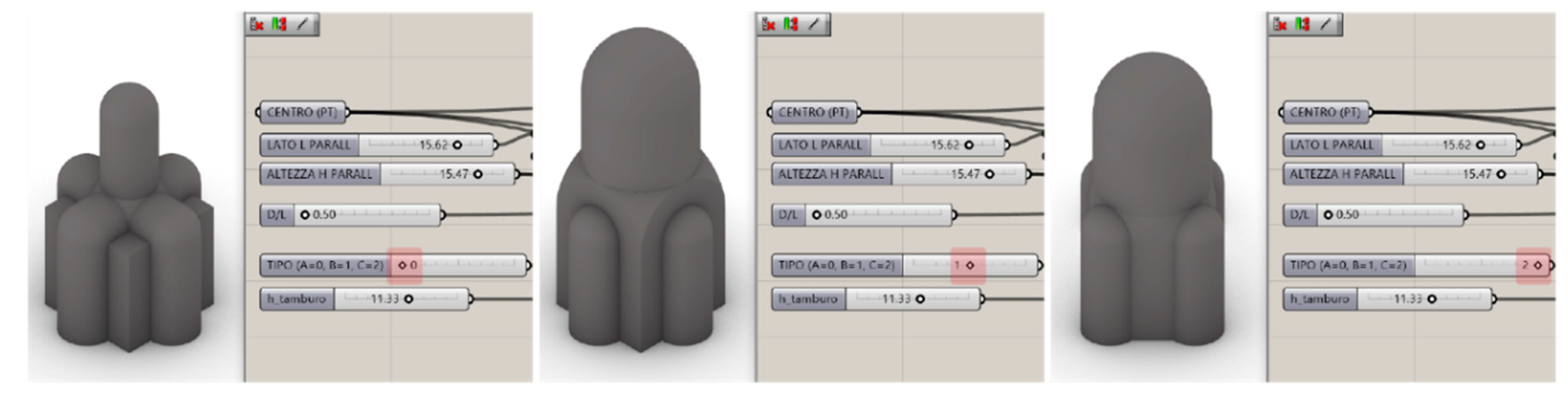
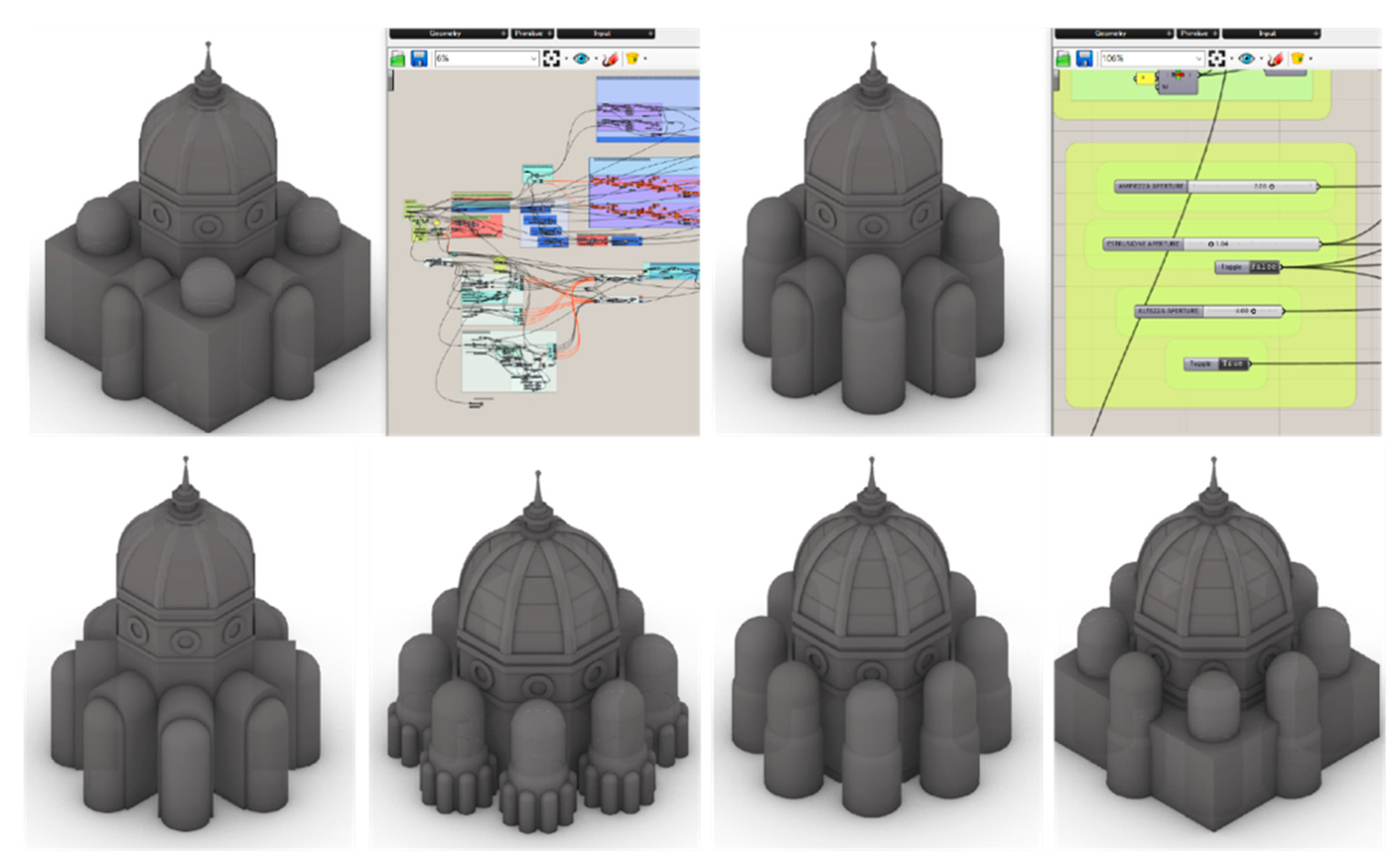
The creation of this tool was fully obtained for the QC chapels, whose level of relatively low complexity makes it possible to easily create a script able to model all their possibilities. In particular, the D/L value is defined through a slider, as well as the height of the elements, while a toggle regulates the choice between the types, A, B and C (
Figure 8).
At a theoretical level, this could be done also for the churches with a central octagonal space, but the computational complexity in this case is higher and would require deeper research and greater accuracy in the development of the script. An attempt was made, and for now, it can represent all the churches that have square, circular and rectangular chapels or chapels made up by a rectangle and a semicircle (-RS chapels). The script also allows regulating the distance of the chapels, the features of the central drum and the type of dome: pavilion (pointed or round, umbrella or spherical) (
Figure 9).
As the first step, the architectural details were kept at a low LoD, sticking mainly to the level of information contained in the drawings, which sometimes appear to be small and schematic. However, in the model we defined, it is possible to regulate the height and protrusion of various architectural elements, like the lantern, the moldings and the window frames and diameter on the drum. This was particularly useful in the subsequent phase of manual modeling in order to speed up and simplify the process.
3. Analysis and 3D Modeling of Each Church
In this section, the second phase of digitization is described. Following the analysis made in the previous step, the churches were considered one by one, and the possible geometrical process for drawing them was researched. This was done by drawing the fundamental lines of the drawings and trying to redraw them through a geometrical process in a CAD environment.
Lastly, the base model produced with the parametric approach was defined in its details, combining it with the considerations made in the plan and elevation analysis. It was often necessary to produce more solutions for each church, either for a lack of information or for inconsistencies between plan and perspective views.
3.1. Plan and Elevation Analysis
Carlo Pedretti was the first to study the proportions of one of Leonardo da Vinci’s buildings with the study he conducted on Drawing No. 238 v of the Academy of Venice, deducing the floor plan from an external perspective view [
32].
On the other hand, Scholfield studied the relation between the octagonal star scheme related to the Pell series and silver ratio and the church depicted in f. 95v of Ms. B [
33]. It is interesting to note that Leonardo seems to reason frequently on eight pointed stars in Ms. B, as he uses this geometric construction both by itself and inside the plan of a church (f. 95 v, Ms. B). These considerations are especially useful because this geometric construction is not only present in f. 95 v, but is widely used in many buildings of the manuscript, which are often constructed starting from a sequence of octagons. The geometrical figure of the octagon is strictly related to Pell numbers and the silver ratio. In fact, given a regular octagon with a unitary side, the in-radius of the octagon equals 1+√2, which is the silver ratio. The silver ratio can be obtained also by dividing two consecutive numbers of the Pell series, and those numbers can also be retrieved by drawing an eight-pointed star from the first octagon and then joining the points.
Then, a systematic study of the drawings in Ms. B was made by Jean Guillaume for the exhibition “
Léonard de Vinci, ingenieur et architecte” for the Montreal Museum of Fine Arts [
28,
34]. Guillaume’s study, in addition to reconstructing in three dimensions some of the churches of Ms. B, developed a complex categorization of the buildings, focused on the chapels and on the apses that surround the central octagonal space.
Francesco P. Di Teodoro then made his contribution in the study of the proportions both of plans and elevations [
25]. One of the elements noticed in his article is that many of the churches in Ms. B are impossible to model with a perfect consistency between plan and perspective view. This problem is probably related to the fact that the drawings Leonardo made in Ms. B are—in Di Teodoro’s opinion —intended as personal notes and do not present yet the characteristics of real-life projects, but this is also frequent when dealing with the digital reconstruction of drawn architecture regarding section and plan view [
20]. The inconsistencies between plan and bird’s-eye view will be constantly considered in our work, since we will evaluate them for each church and try to understand the reasons behind these differences in the drawings.
The proportional and geometrical analysis described in this section considers these contributions. The approach is thus aimed at systematically comprehending the proportions and the recurring elements. For this purpose, understanding the previous classifications of the churches was fundamental as it constituted the starting point for the geometrical analysis and for the addition of features to the 3D model.
In order to better explain the process, the case of the church depicted in f. 22r (
Figure 10) is reported and described. The church consists of a central regular octagonal space, with niches on its oblique sides, connected with eight chapels, alternated in shape, that are disposed around it along a square and that are enveloped by a square-based volume. The chapels on the diagonal axes are circular, while the ones on the XY axes are a variant of the four lobed chapel analyzed in
Figure 7. However, as will be explained in the next subsection, it is not clear whether they should be classified as Type B (i.e., a square central space with niches in its sides and the drum leaning on spherical pendentives) or Type C (i.e., an octagonal space with niches on the major sides of the octagon and a drum that leans on pendentives, which are modeled as the example of
Cappella Chigi in Rome and solve the transition between the octagon and the circumference). For all these reasons, this church can be classified as R/Q/A-QC(b) D-C/BY and R/Q/A-QC(c) D-C/BY (depending on the type of chapel, QC is considered on the main axes).
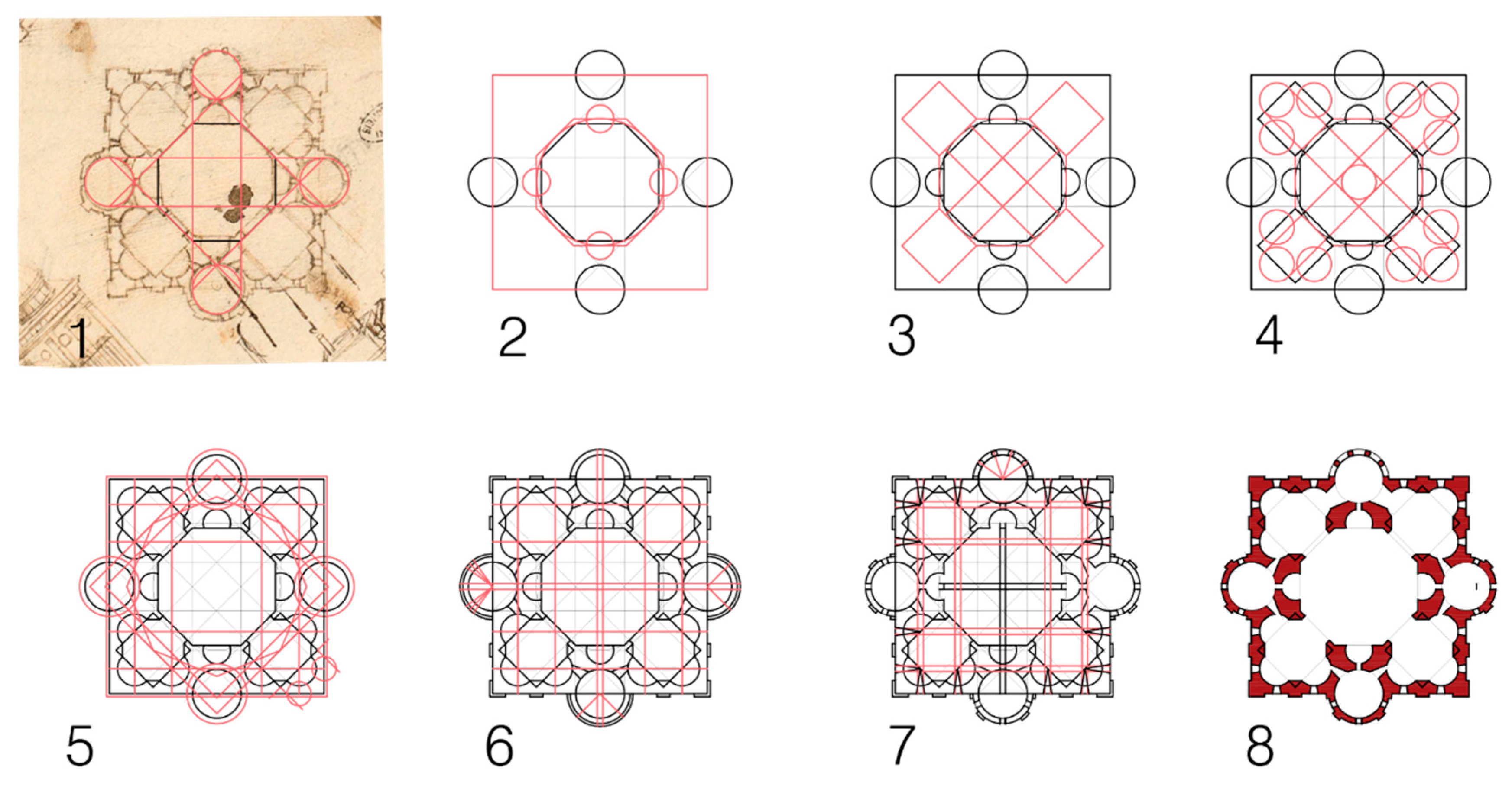
The process starts with the representation of the plan and its deconstruction, in order to define the geometric process that Leonardo could have used to design the church (
Figure 11). In this case, starting from the central octagon and lengthening its sides and diameters (i.e., following the construction of the octagonal star of the Pell series), it is possible to find the extremes of the circular chapels’ diameters (1). With a succession of geometrical operations (2–4), the other chapels’ shapes are defined. Then, based on the geometries defined, it is possible to trace the interior and exterior openings (5–7) and to finally hatch the masonry portions (8).
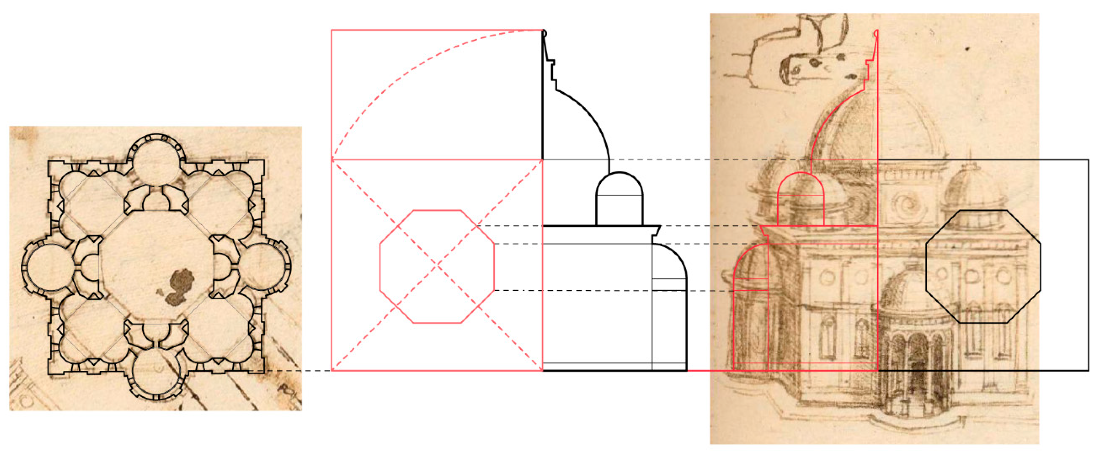
Then, the elevation is analyzed, trying to find a relation between the dimensions of the elements in the plan and their height (
Figure 12). In order to do so, first, it is necessary to scale the bird’s-eye view drawing based on the plan. The fact that the perspective views are almost cavalier projection represents a useful characteristic to derive the measures of objects, since the façade is almost an orthographic elevation. In the example reported here, the height of the different elements was put in relation with the width of the square in plan and with the octagon. Moreover, the total height of the edifice can be related to the golden ratio of the square itself.
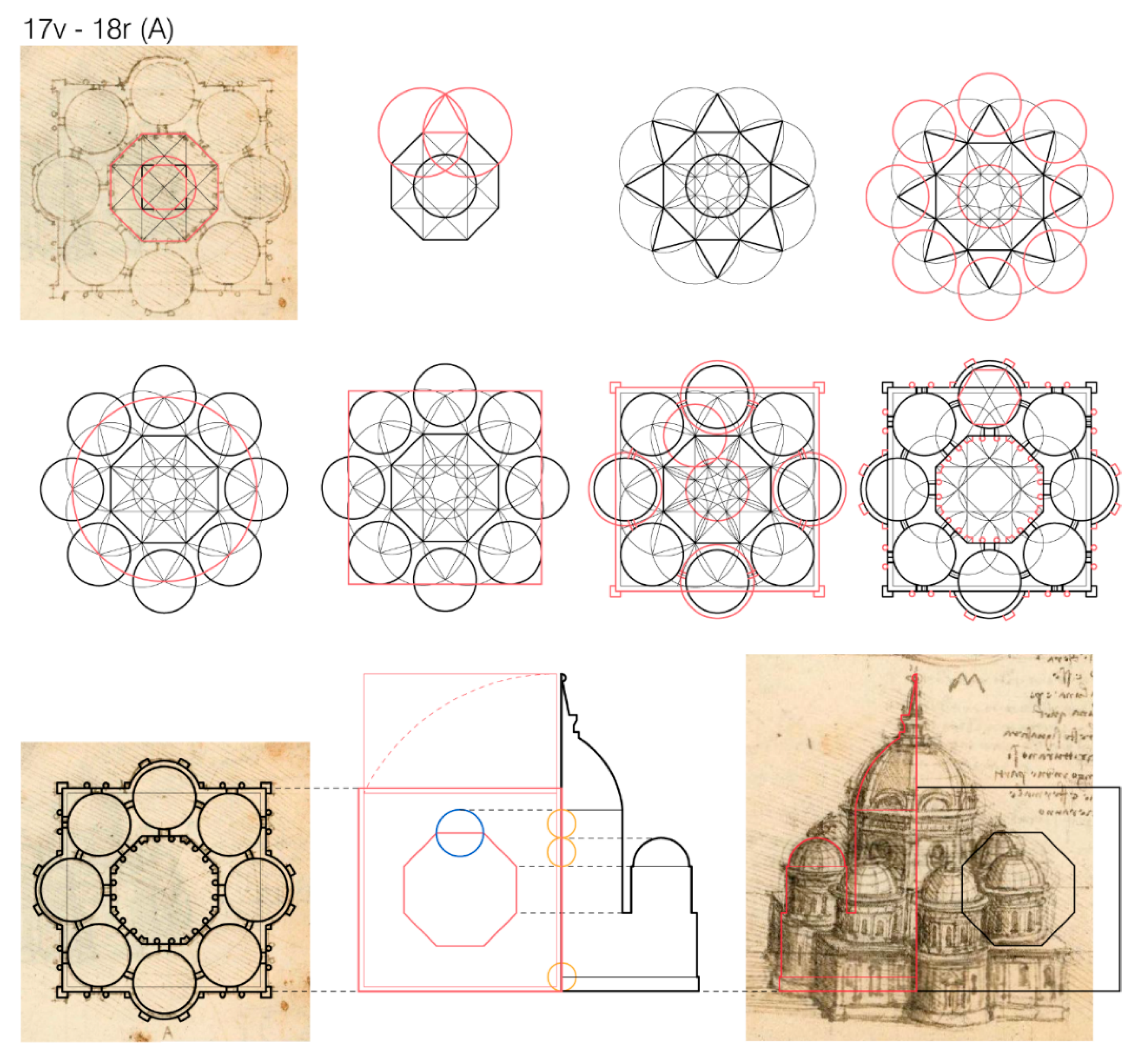
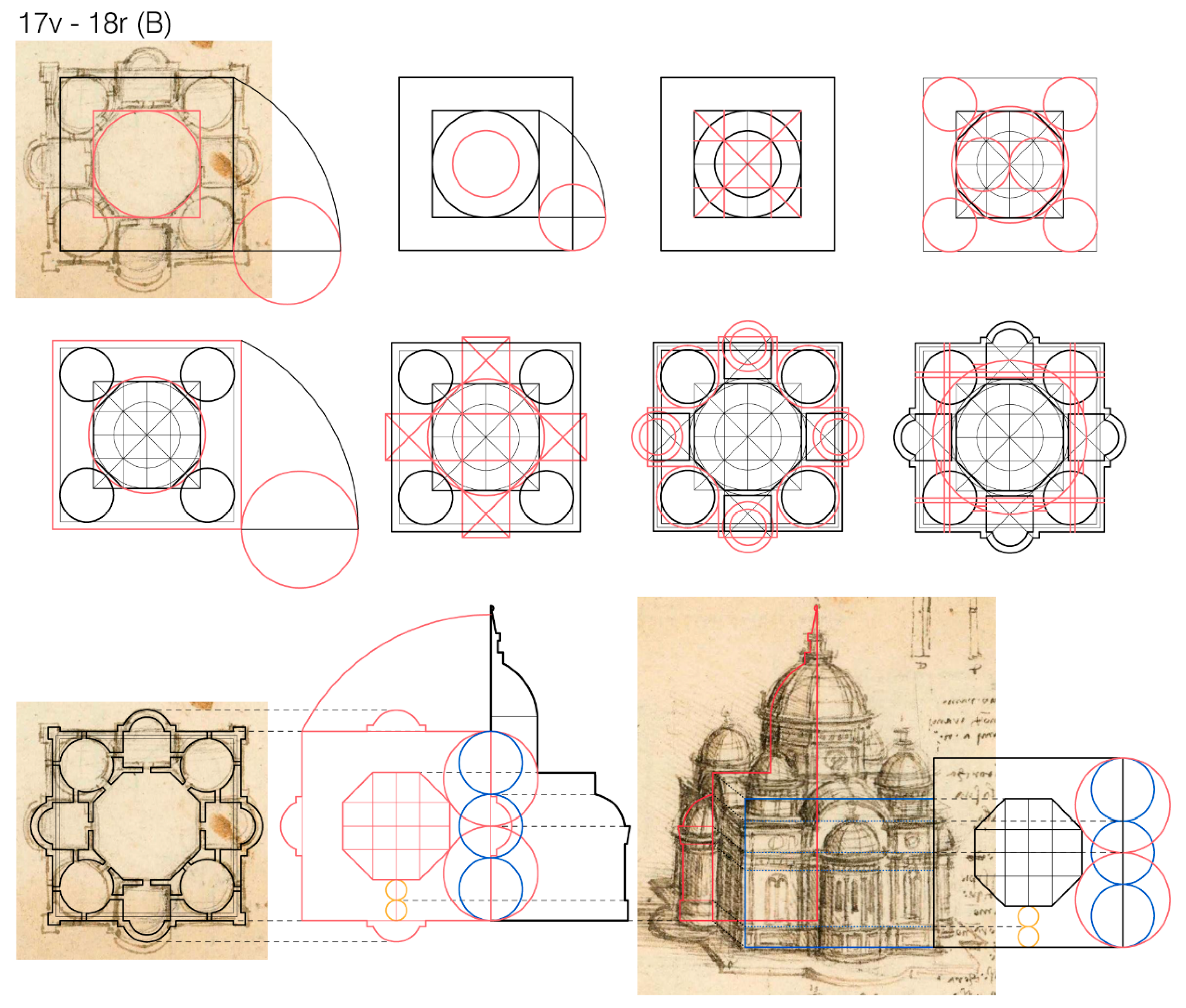
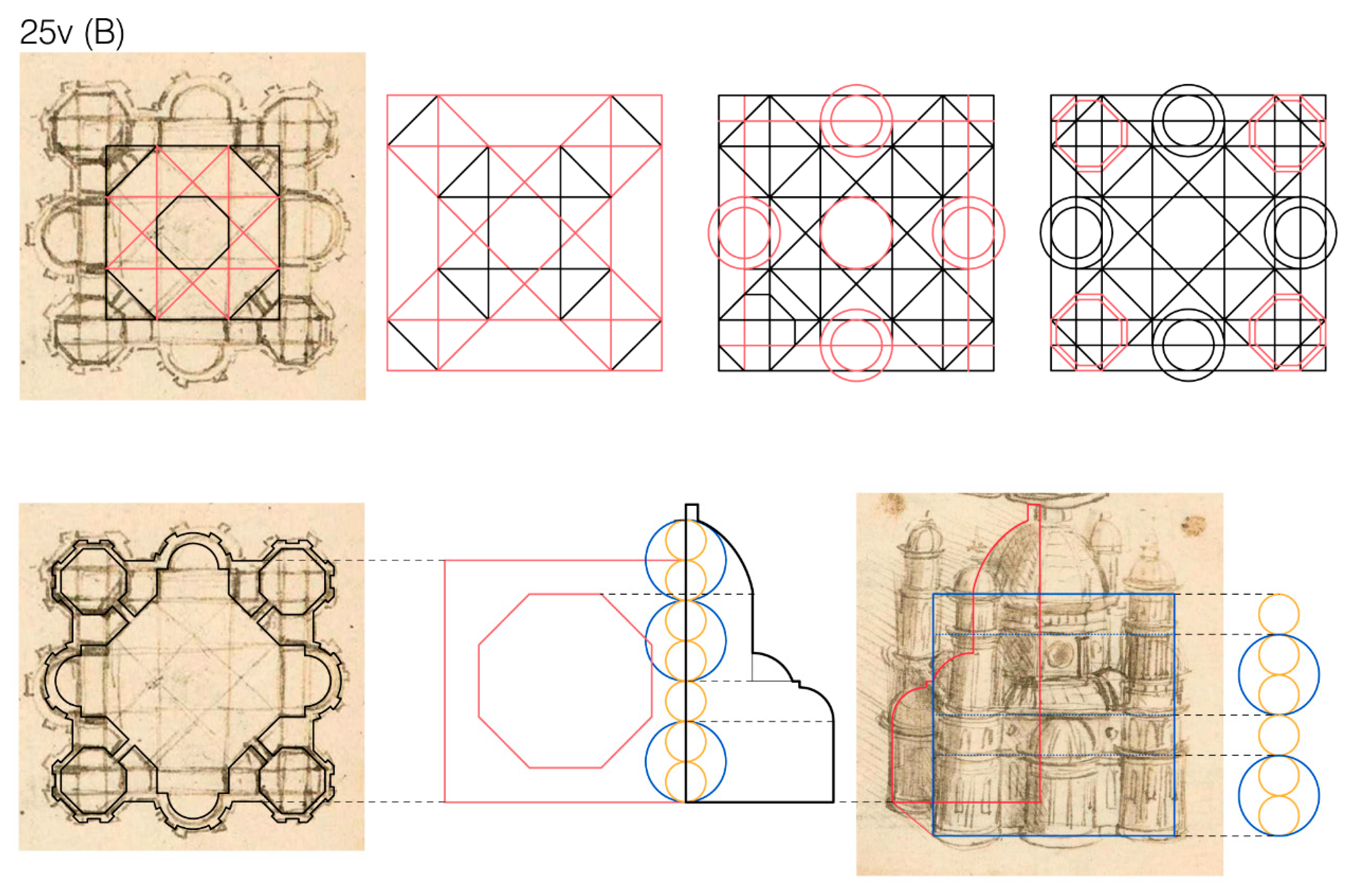
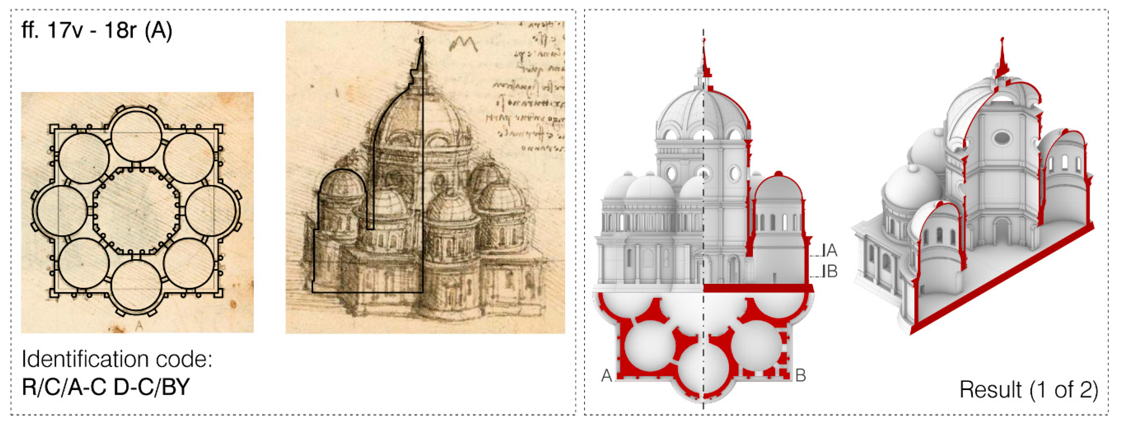
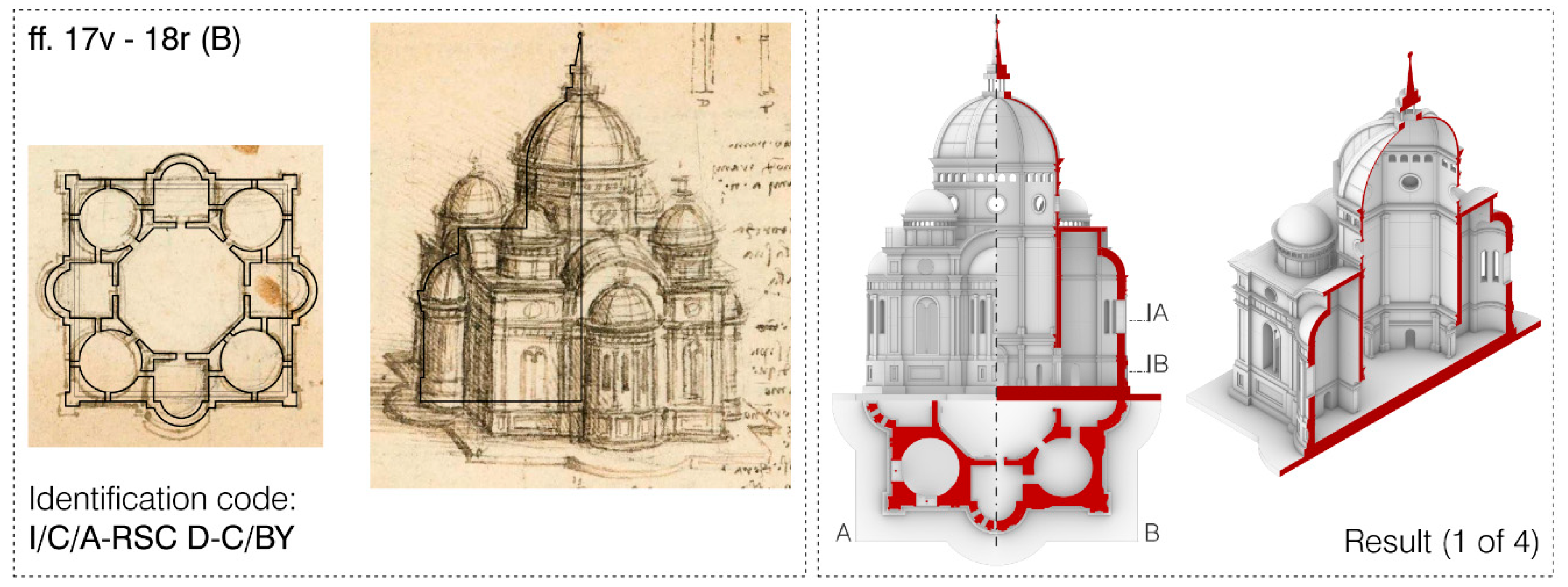
The same process was conducted for all the churches, and a recurrence in the use of the golden and silver ratio in plan—and sometimes also in elevation—could be noticed. Three more examples are reported here showing the results obtained for the two churches represented in ff. 17v-18r (called here A and B) and for one of the two churches depicted in f. 25 (
Figure 13,
Figure 14 and
Figure 15).
In the church depicted in ff. 17v18r (A) (
Figure 13), the use of the silver ratio through the construction of a smaller octagon inside the central one allows us to find the diameter of the eight circular chapels, while the golden ratio can be used to retrieve the total height of the building.
In the church labeled as (B) in the same folios, ff. 17v and 18r (
Figure 14), the golden ratio can be used to relate the width of the central octagon and that of the enveloping square-based volume. In turn, the same relation can also be used to find the sides of the irregular octagon. Furthermore, in this case, the total height of the building can be put in relation with the square-based volume and its golden ratio.
In one of the churches depicted in f. 25v, here labelled as B (
Figure 15), Leonardo uses once again the Pell series through the construction of a sequence of two octagons. The extension of these guiding lines can be used to define the dimension of the chapels. In this case, the elevation can be put in relation with fractions of the enveloping square-based volume width.
Therefore, as can be seen from the previous examples, the churches show a certain regularity in plan, and the geometric process for this can be obtained relatively easily, also thanks to the presence in some cases of guiding lines (visible for example in
Figure 15). The façades, on the other hand, are not so easily analyzable, and even though a specific study for them could be developed in the future, we just focused on looking for the relations between the main architectural elements’ height and the geometries used for the construction of the plan.
3.2. Final Modeling of Multiple Results
At this stage, all the churches were digitized one by one using a manual approach in a 2D and 3D CAD environment, starting from a proportional study and using the results of the parametric approach, explored in the previous section. In fact, once having defined the classification code and the proportions between the elements’ heights and width, it was possible to insert them into the Grasshopper script and to bake a low LoD model from which to start.
Then, for each inconsistency between plan and perspective views, a different 3D model was created. Then, more variants were modeled also in the case where Leonardo draws different solutions in the same drawing, varying the architectural elements. Moreover, the absence of a section view sometimes makes it impossible to have certainties about the structure of the interior. To overcome this issue, in the case of uncertainty, more solutions were explored, referring to the architectural examples that Leonardo might have seen during and before the writing of Ms. B.
For instance, regarding the example of f. 22 r, it was necessary to consider three elements of variability, each one corresponding to one of the categories described above:
- (a)
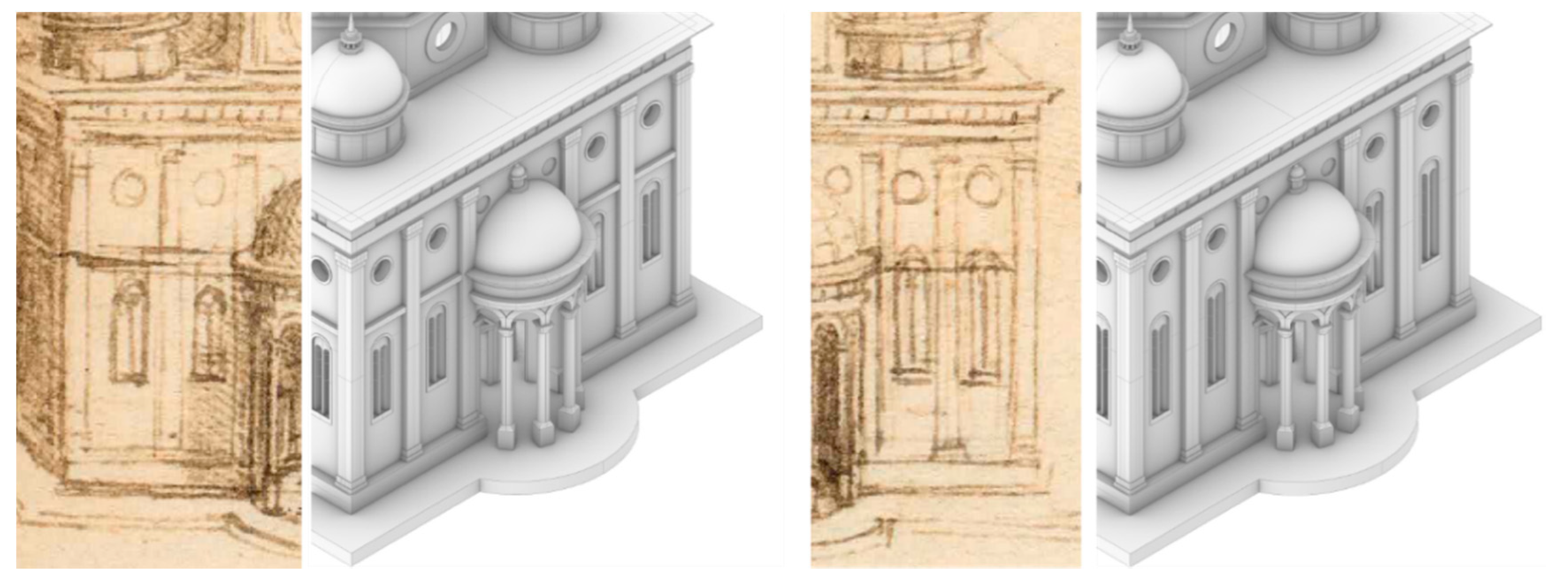
The inconsistency between plan and perspective view regarding the width of the pilasters and the position of the double arched windows (
Figure 16).
- (b)
The difference between the right-hand side and the left-hand side of the façade in the height of the double arched windows (
Figure 17).
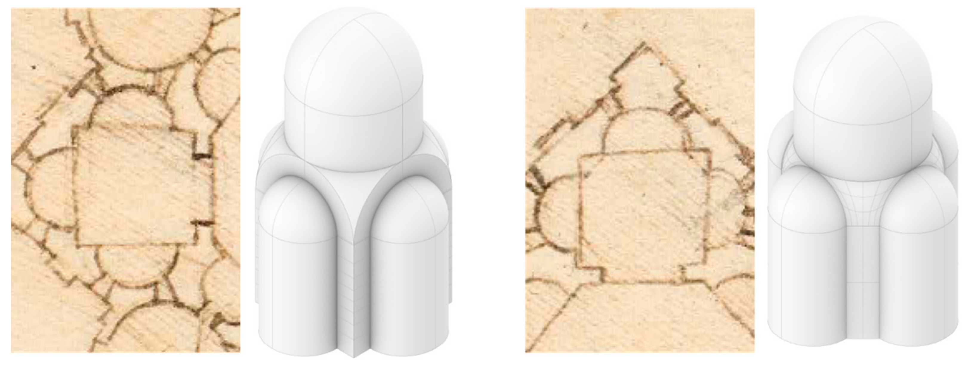
- (c)
The interior shape of the QC chapels in plan, since it is not clear whether they should be classified as Type B (i.e., a square central space with niches in its sides and the drum leaning on spherical pendentives) or as Type C (i.e., an octagonal space with niches on the major sides of the octagon and a drum hat leans on pendentives, modeled according to the reference of
Cappella Chigi in Rome) (
Figure 18).
Therefore, the overall number of solutions produced in this case is eight (i.e., 2
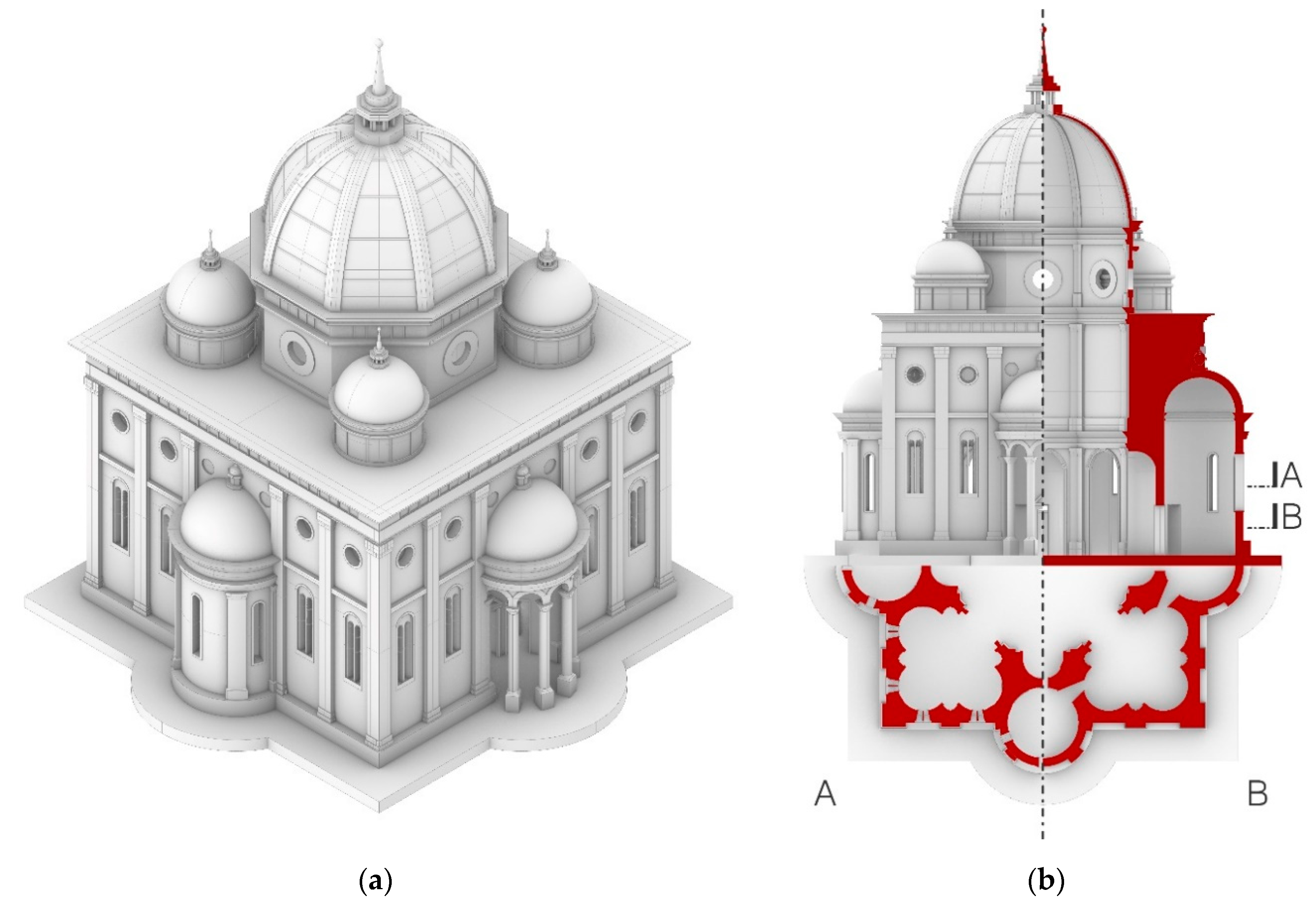
3), each one related to the modification of one of the elements listed above. This example is emblematic of the great number of results that were necessary to create in order to digitize sixteen churches. One of these solutions can be seen in
Figure 19.
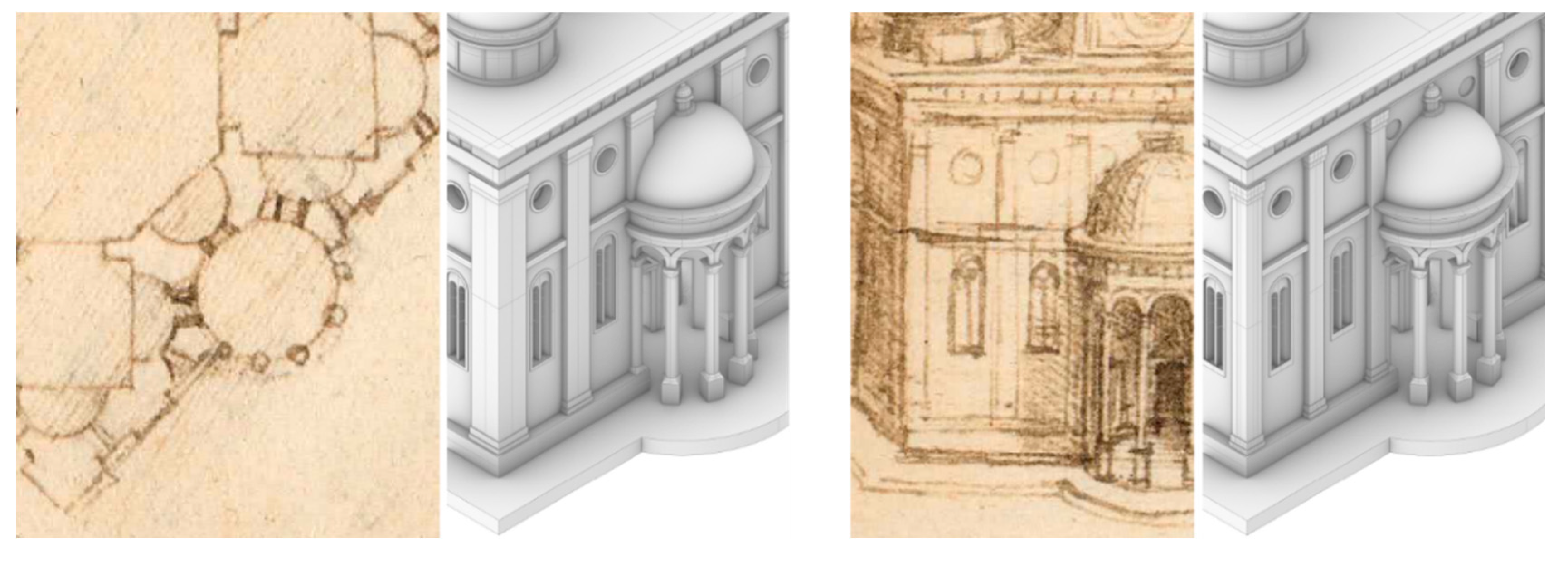
As we mentioned above, the small dimension of the drawings and the lack of information about the interior required us to use references as a guide for the 3D reconstruction. Several sources were collected specifically for the architectural elements that Leonardo repeats in the layouts of the churches of Ms. B, i.e., the octagonal drum with an upper entablature divided into three parts and the circular windows, the ribbed octagonal dome, the apses with an alternation of pilasters and single arched windows and the façade’s architectural details. Therefore, for each of these elements, we collected a list of edifices coeval to the drawings of Ms. B and relevant to it (for instance, for their similarities to Ms. B’s churches, because they were also centrally planned, or for the contacts that Leonardo may have had with their authors).
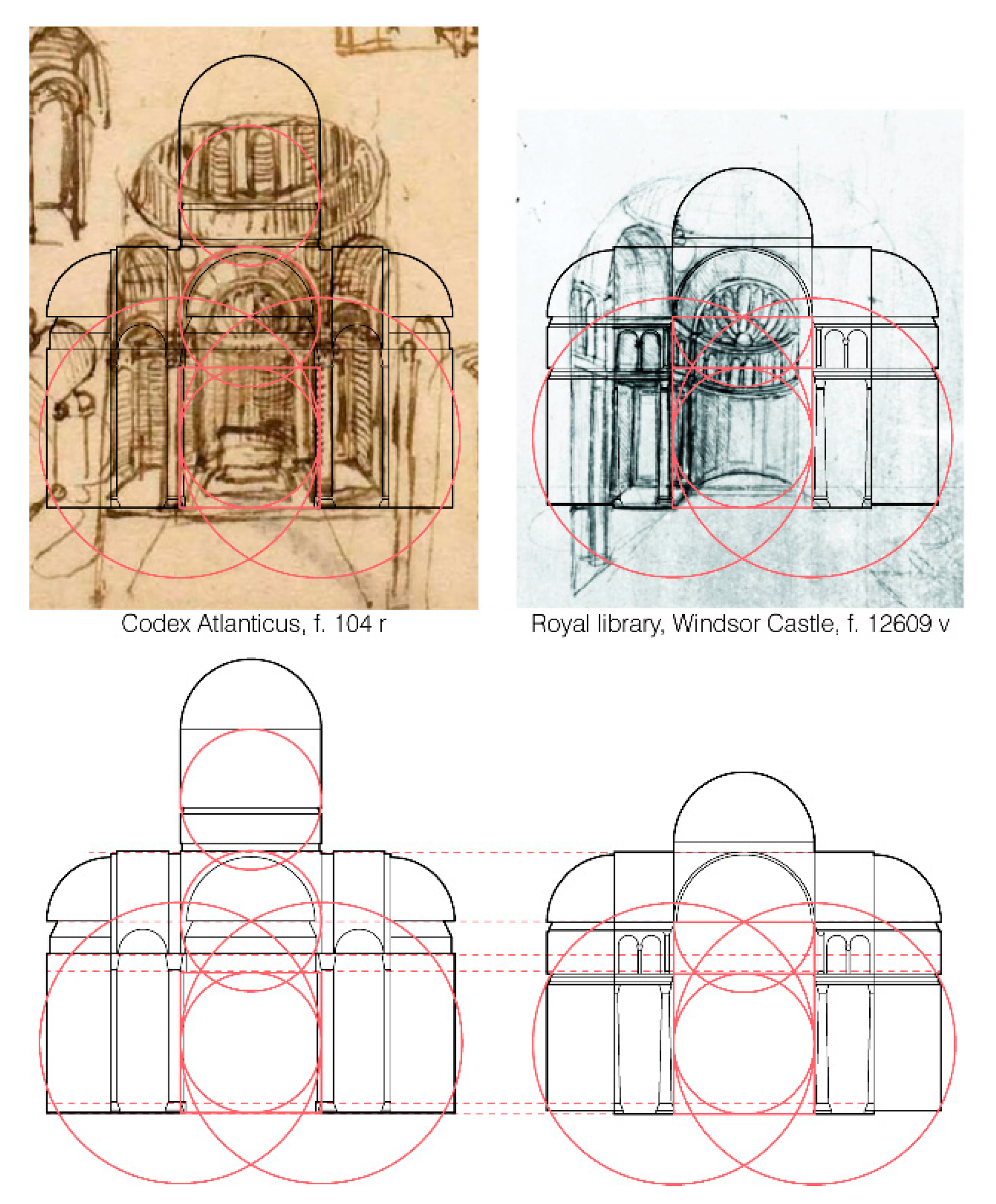
In order to make assumptions about the interiors of the buildings among Leonardo’s drawings, at this time, only the two perspective sections drawn by Leonardo, CA, f.104 r, and RL, f. 12609 v [
35], are possible references. However, these perspective sections refer to the four lobed plan layout and, then, in the case of f. 22r, are useful to model the interiors of the chapels placed on the diagonal axes and not the interior of the central octagonal space. The proportions between the elements of these perspective sections are, interestingly, the same (
Figure 20).
Regarding the hypotheses we can make for the interior of the octagonal space of all the churches, the references that could be considered are, among the coeval ones previously collected, the ones that show a semi-pilaster in their corners between two columns or semi-columns that give access to the chapels, since this is a feature that Leonardo draws in the most accurate drawings of Ms. B, like f. 95v and others.
For all the solutions, we attempted to make a hypothesis about the dimension of the building, based on the architectural elements’ width. The typical dimensions of the different kinds of openings—single and double arched windows, circular windows, interior and exterior doors—collected from coeval and relevant architectural references, were used to scale the 3D object and try to find the solution that could make the dimensions of all these elements realistic at the same time. To obtain a likely range of width and height values, the dimensions of these five elements were extracted from an existing traditional survey of the reference architecture previously collected.
For the sake of clarity, one variant for each of the churches previously analyzed in their geometry and proportions is reported here along with its identification code.
4. Results
The work described in
Section 2 led to a classification method and a tool for modeling the churches in a low LoD, which helps in the visualization of the aggregative rules behind the churches. Moreover, the script is useful to appreciate the great number of combinations that could respond to these rules. The highest difficulty found in this process was the computational time: it would be necessary to redesign the script with a higher efficiency before adding the other chapels’ shapes, but we think this could be an interesting element to develop in the future. In particular, the time that was necessary to compute a single model and modify its parameters in Grasshopper differs from church to church, depending on its complexity, but spans approximately from a few seconds to about half a minute (with reference to a machine running Rhino 6 and Grasshopper on Windows 10 Pro 64 bit on one 2.8 GHz Intel Core i7 7700HQ CPU with two cores and 8 GB of DDR4 RAM); e.g., regarding the churches analyzed in the previous sections, this is on average equal to 8.5 s for f. 22r, 13.5 s for ff. 17v 18r (A), 33.0 s for ff. 17v 18r (B) and 10.8 s for f. 25 v (B).
Then, in
Section 3, the results are represented on the one hand by the extrapolation of a possible geometric process for the reconstruction of the drawings and, on the other, by several possible 3D solutions for each church (
Figure 21,
Figure 22 and
Figure 23).
Another result emerging from the study of the drawings is that there is a recurrent use of the golden and silver ratio in the construction of plan views and that the fundamental elements of this process are almost always related in some way to the height of the parts in the perspective view. This also shows the presence of a relatively complex geometrical construction behind the designs, which are apparently very simple and sketchy. It is interesting to see how all these peculiarities could not have been noticed without a thorough work of combined analysis and the deconstruction of the two views.
As we anticipated, one of the most interesting results that we could observe from the digitization work is that for the majority of the churches, it was necessary to produce more than one three-dimensional solution (in particular, the total amount of solutions that were realized for the sixteen churches is equal to sixty-seven). This is related to two different kinds of variables:
The first variable is deeply related to the fact that these drawing are personal annotations, and this proves that by drawing, Leonardo is exploring solutions and testing them. The fact that these drawings were meant for personal annotations is also proven by the lack of accuracy in many of them; in fact, the more the churches are characterized by a simple layout, the more their representation is just schematic.
The second variable concerns both previous elements. In fact, as emerged from the digitization process, there are some inconsistencies that are evident and are related to the exploration of different solutions, while others are due to problems of imprecision or schematism in the drawings.
Therefore, this practical work shows its utility also in gaining information about the drawings and drawing historical and artistic conclusions and hypotheses.
As regards the layout of the churches, we could notice how Leonardo does not converge, through the pages of the manuscript, on a solution. Instead, he explores multiple possibilities in a nearly combinatory work. This, along with the other results previously pointed out, weighs in favor of the theories that want this speculation not to be meant for the design of any church. It is in fact more likely, in our opinion, that a work of this kind could constitute the basis for a later creation of a treatise on centrally planned churches.
Lastly, all these results enable us to make some considerations about the representation techniques used in the manuscript. The use of a plan and a bird’s-eye view is in contrast with what was claimed by L.B. Alberti [
36] and Raffaello [
37] regarding the representation tools for architecture, and we will try to give an explanation to this difference. First, it is interesting to notice that the method used by Leonardo could in turn show some affinities to the drawing instruments listed by Vitruvio:
ichnographia,
orthographia and
scaenographia [
38]. In fact, Leonardo’s bird’s-eye views could be considered as a combination of the two last instruments, since they show a façade that is almost an orthographic view of the elevation (
orthographia) together with a perspective view that gives information about the volumes (
scaenographia), and those are paired with a plan view (
ichnographia). Of course, as was claimed, the perspective on which Vitruvio writes might be different from that of Leonardo, and it may be a central perspective with the observer placed at a lower height. However, with this disposition, Leonardo manages to also add information about the roof in the same drawing.
It is reasonable to think that the graphical decision of Leonardo ultimately must be related to the purpose of the drawings, and thus to the information they are able to convey, and to the features of the edifices. First, the bird’s-eye view enables obtaining a synthetic overview of the whole, with attention to the way the volumes are spatially assembled, and this is particularly fitting for the recurrent layout of the churches, which is made by the aggregation of elements around a central space. Then, as we anticipated, the drawing is also able to give information about the roof and about the proportional measures in the façade, while the associated plan is fundamental to know about the circulation inside the edifice. Moreover, the final effect is very similar to that of a model placed on a table, as was noticed by Pedretti [
31], and we know that the combined use of a plan view with a wooden model was not something rare in terms of architectural communication in the Renaissance. Moreover, L.B. Alberti also claimed the importance of the creation of a model in order to be aware of the problems of a project [
36], and our analysis showed once again that Leonardo was using the drawings as a reasoning instrument.
To conclude, the representation technique developed by Leonardo appears to be, on the one hand, extremely effective for rapidly annotating ideas and testing solutions and, on the other, a powerful tool to convey immediate volumetric information along with measurable, orthographic views.


