
Performance of a Salt-Accumulating Substitution Lime Render for Salt Laden Historic Masonry Walls


1
GeoBioTec, Department of Geociences, University of Aveiro, 3810-193 Aveiro, Portugal
2
Buildings Department, National Laboratory for Civil Engineering, 1700-066 Lisboa, Portugal
3
Risco, Department of Civil Engineering, University of Aveiro, 3810-193 Aveiro, Portugal
*
Author to whom correspondence should be addressed.
Heritage 2021, 4(4), 3879-3891; https://0-doi-org.brum.beds.ac.uk/10.3390/heritage4040212
Submission received: 14 September 2021
/
Revised: 8 October 2021
/
Accepted: 18 October 2021
/
Published: 21 October 2021
(This article belongs to the Special Issue Built Heritage Conservation and Climate Change)
Abstract
:Salt crystallization is one of the main decay processes in historic masonry mortars, and climate change can worsen the salt weathering effects on those materials as result of, e.g., more often rain falls, more intense solar radiation and sea level rise. In this paper, the effectiveness and durability of a substitution “ventilated render” system (a two-layer render, with base and outer layer and “vertical grooves” in the base layer) on a full-scale salt laden masonry wall to reproduce conditions that may be found in real cases was investigated. The crystallization at the interface between render layers and in vertical grooves and the effect of the porous structure on salt crystallization were thoroughly investigated. It was highlighted the reliability of the results of the salt crystallization testing procedure on a full-scale masonry wall to attest the efficiency and durability of the render system. Finally, it was proven that the ventilated render system with water repellent in the outer layer is durable and efficient enough to be used as a substitution render on salt laden historical masonries, acting as a salt accumulation render where salts preferably crystallize in, delaying the damage on the outer surface without introducing harmful effects in the masonry.
1. Introduction
Salt crystallization is one of the main decay processes of mortars (porous construction materials) [1,2,3,4,5,6], and it is especially relevant in old buildings, i.e., those built before the use of independent Portland cement concrete structures. This decay process, in historic masonry mortars, results from the interaction between mortars composition and external conditions, such as temperature and relative humidity. Climate change can worsen the salt weathering effects on those materials as result of, e.g., more frequent rain falls, more intense solar radiation and sea level rise [2].
When salt decay happens and mortars need to be substituted, laboratorial salt weathering tests on substitution mortars can be performed to evaluate their durability and efficiency, although a commonly accepted protocol on those tests does not yet exist [7].
In historic masonry walls, both rising damp and soluble salts are often present. The salty solution may be transported to the porous network of renders and masonry materials through the foundations. In these materials they may crystalize as result of solution supersaturation, mainly due to changes in the evaporation rate and temperature. A necessary condition for salt damage to occur is the presence of moisture, although practice shows that even when preventing moisture ingress in the porous materials, salts may still cycle due to relative humidity changes [8,9]. If salt crystallization happens inside the material, as subflorescences, the volume and pressure in the porous structure increase and may induce severe damage. As a result, render detachment or loss of cohesion may occur at the evaporation zone [10], and the renders may need to be fully replaced.
Transport and accumulation systems are being proposed as replacement renders to provide a more durable solution for salt laden historic masonries in the presence of water capillary rise [8,11,12]. The major benefit of both systems is to prevent crystallization within the masonry, while accumulation systems seem to be more durable when compared with other renders existing in the market [8]. Moreover, they are easier to execute, more effective and reversible, in case they need to be substituted they are easily removed, when compared other techniques used to reduce rising damp uptake, such as chemical, electroosmotic and physical barrier solutions [13], mainly due to historic masonry’s great heterogeneity, both in terms of materials and thickness.
The existing salt crystallization tests may result in damage patterns different from those observed in practice and, as result, a commonly accepted protocol does not exist [7]. Most of the renders that contain water repellent additives show slow absorption and drying ([14] and references therein). Previous experiments have shown that, in crystallization tests, damage appears only after several months of testing in laboratory conditions, and in case of specimens contaminated with NaCl, a discrepancy between the limited damage patterns observed in laboratory and the severe damage occurring in practice has been observed [7,15]. The use of a NaCl concentration similar to seawater could be a more realistic approach for testing the durability of renders in coastal environments [16]. Additionally, the use of small-scale specimens is being proposed to save materials and speed up the tests, as absorption and drying time is reduced, although it may result in damage patterns different from those observed in practice [7].
In this article the results of an extensive research on an innovative accumulating render (denominated “ventilated render”) to be used as a replacement render for historic masonry walls submitted to rising dampness levels of sodium chloride solution are discussed. The render system was especially designed to allow the accumulation of salts within it and its performance is discussed considering the masonry and outer layer salt accumulation and its durability and protection ability, compared with traditional lime renders, after testing on a full-scale masonry wall (in laboratory).
The innovation of this study is the investigation of the influence of the developed substitution render systems applied on a full-scale masonry wall on salt distribution between masonry and render layers and on the damage patterns resulting from the crystallization cycles with a sodium chloride solution. Although very time-consuming, the experimental work was developed on a full-scale masonry wall to be representative of common practice in historic masonry walls, with a more realistic combination of materials (masonry and render systems). The ventilated render system that shows the best behavior is expected to be used in practice for salt laden historic masonry walls showing active salt cycling. As a result, the present paper intends to be a step forward in relation to the previous research [11], as explained in Section 2.
2. Background and Research Aims
In the preliminary experimental procedure developed by the authors [11], the salt resistance of the developed lime-based render systems in small scale specimens was developed under laboratorial controlled conditions. The procedure was developed as follows:
- Six small scale specimens, four with vertical grooves in base layer (to induce salt crystallization in those grooves) and outer layer without grooves and two without grooves, composed by four different formulations, were applied to traditional solid bricks in both larger sides. After curing for 3 months, six crystallization cycles were performed using a sodium chloride solution. Each cycle comprised an absorption stage (by partial immersion during approximately 7 days at 20 °C and 65% RH) and a drying stage (in a ventilated oven over almost a week) until constant weight.
- From this research [11], it was concluded that the “ventilated render system”, with vertical grooves (to induce salt crystallization inside them) and brick powder in the base layer and water repellent in the outer layer, seemed to be durable and efficient for application on salt laden walls. This render system seemed to work as an accumulating render system, enabling salt accumulation at the vertical grooves of the base layer and delaying the damage at the outer surface, when compared with the other tested solutions, and seemed to prevent salt accumulation in the substrate. At the interface, salt accumulation was not observed that might result in the premature detachment of the outer layer.
Based on those preliminary results, in the present investigation, a new experimental campaign was performed considering some key advances:
- A full-scale masonry wall is used instead of small-scale single brick specimens to validate the results from the accelerated tests considering the interaction of the different materials in the masonry, as observed in practice.
- The “ventilated render system”, a second render system similar to the previous one but without water repellent in the outer layer and another two render systems, with the same composition as the two previous ones but without grooves, were tested to compare their performance.
- Two weathering cycles were carried out instead of six, as similar damage at the end of those cycles was observed in the render systems tested in both experimental campaigns, although these two weathering cycles in the full-scale masonry took longer than the six previous ones in small-scale bricks.
The present investigation aimed to assess the durability of the “ventilated render system” submitted to salt weathering on salt laden masonries and calibrate and prove the efficiency of the laboratory method previously implemented [11] to test renders under those conditions, taking into consideration the results obtained in the present work in more realistic conditions.
3. Materials and Methods
The experimental research program was performed in the laboratory, concerning the simulation of severe action of salt laden water on the rendered full-scale masonry wall.
In real walls, salt solutions typically migrate from the interior of the masonry towards the outer surface of the plaster/render. Salt crystallization tests are absorption and drying tests performed on the full-scale masonry wall by submitting the wall to rising damp with a salty solution. They are in fact artificial ageing tests that simulate the actual severe action, as they evaluate salt damage and not only moisture transport. For these tests, high concentrations of salt solution and repeated contaminations and changeable environmental conditions were used in order to achieve damage.
To test the render systems, an experimental program was developed in the laboratory in non-conditioned environment, simulating real conditions of salt laden water in a historic masonry wall.
3.1. Render Systems and Full-Scale Masonry Wall
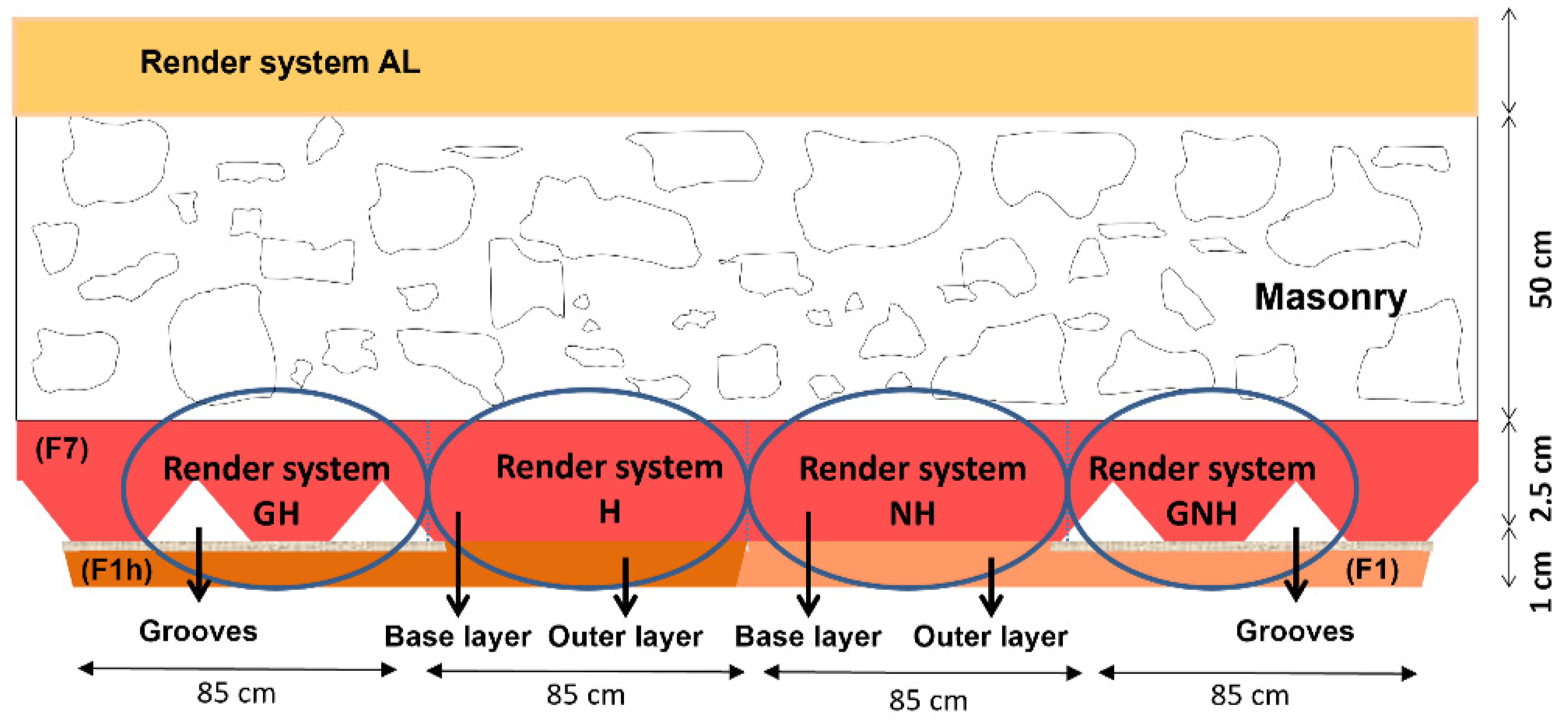
The render systems are a two-layer render system (base and outer layer) that intends to work as a salt accumulating render. The vertical grooves of the base layer were executed with a metallic comb, and a glass fiber grid was used between the base and outer layers to avoid filling the grooves during the application of the subsequent mortar layer (Figure 1).
The render systems with grooves (GH and GNH) were selected from a previous work [11], and new developed renders without grooves (NH and H) were tested in the masonry wall. A traditional lime render (AL) already existent on the masonry [17] wall was also used for comparison purposes. The GNH render system is similar to GH but without water repellent in the outer layer; NH and H are similar to GNH and GH, respectively, although without grooves in the base layer.
The tested render systems mortars composition and layers formulation and their main characteristics are described in Table 1 and Table 2.
The admixture used in F7 (Table 1) render layer is a mineral addition used to increase the pozzolanic reaction velocity. Water uptake takes place by capillarity through the connected pores mainly between 0.01 and 10 µm (the capillary range pores dimension) [10]. The samples show a range of the porosity between 15.9% and 24.7%.
The full-scale masonry wall (350 cm × 270 cm × 50 cm) is composed by calcareous stone and lime bedding mortar rendered on larger side A with the traditional lime render (AL) 2 cm thick (1:3 binder: aggregate dosage by volume). The bedding mortars have the same composition as the traditional lime render (AL). The wall was erected on a plastic tray to make it possible to submit it to salty water capillary rise through the base of the masonry.
The render systems GH, H, NH and GNH were applied on the full-scale masonry wall (larger side B), with 3.5 cm of total thickness, 1.8 m height and approximately 85 cm large (each one). The lateral (right and left) sides of the wall were rendered with water repellent within the render (H) to avoid preferential moisture transport and evaporation in this direction.
The render systems were carefully applied by experimented workers to reduce problems due to inadequate workmanship. Water spraying twice a day during the first five days of curing was performed to enable the pozzolanic reaction to happen before carbonation [15] to allow better mechanical and physical performance of those mortars.
A schematic representation of the four render systems (GH, H, NH and GNH) can be found in Figure 2.
3.2. Salt Crystallization Tests
After 3 months of curing, an experimental program was performed in the laboratory in a non-conditioned environment to simulate real conditions of salt laden capillary water rise on a real masonry wall. The wall was contaminated by partial immersion in an NaCl aqueous solution (concentration 27 g/L—similar to sea water [16] with a 10 cm level that remained constant during capillary rise). The two cycles of capillary rise with NaCl aqueous solution and subsequent drying were performed to study the durability (salt damage) and efficiency (masonry protection ability) of the studied render systems when moisture and salts are present due to capillary rise. Each cycle was performed during 2 months of partial immersion to allow capillary rise with salt laden water until constant height, followed by 6 months of drying. The drying front in render systems was observed until 0.9 m of height in the outer surface of the render systems.
3.3. Render Systems Characterization
Pull-off tests were performed following European standard for pull-off tests on renders EN–1015-12:2000: Methods of test for mortar for masonry and determination of adhesive strength of hardened rendering and plastering mortars on substrates [18]. This test is based on the tensile stress that is necessary to pull out a metallic disc with a coat of mortar from the substrate and is related to the mortar’s tensile adhesion strength. To execute this semi-destructive test, a metallic disc was glued to the surface of the outer layer. A tensile force is produced and exerted on the area where the metallic disc is glued. For external renders of old buildings, as is the case here, the minimum value of adherence is 0.1 N/mm2 or the cohesive rupture of the mortar [19]. The objective of the test was to evaluate the type of rupture and if it happens between the outer layer of render systems and the base layer (GH and GNH render system) or between the render and the support (H and NH render systems). Pull off tests were performed before the cycles. The tests were carefully executed on the wall, to avoid damaging GNH and GH render systems with grooves.
Before experiments and at the end of 1st and 2nd cycles, samples were removed from render systems to enable chlorides quantification by potentiometric titration following NT BUILD 208: Concrete, hardened: Chloride content by Volhard titration [20]. This method determines the total chloride (in %) through extraction with diluted nitric acid using the specimens reduced to powder (ϕ 100 µm) by direct potentiometry with a chloride-sensitive electrode. The samples were removed from each render system at wall by drilling at different heights (30, 60 and 120 cm), taking into consideration the whole thickness (from the external layer until the substrate), at low rotations per minute to prevent the disaggregation of the sample. The different layers of each sample (outer and base render layers) were taken into consideration.
At the end of 2nd cycle, damage in the outer surface was visually evaluated in terms of severity of damage and efflorescence quantity.
Complementary analyses were carried out at the end of 2nd cycle: The stereomicroscope observations were performed on the substrate and inside the grooves at low magnification (×70) to detect special features; the Scanning Electron Microscopy (SEM) observations were performed on samples removed by drilling at 0.30 m height from damaged and non-damaged zones of each render systems, considering the whole thickness (from the external layer until the substrate), to better understand the different damage patterns and salt accumulation on render systems. SEM was performed using a Joel JSM-6400 SEM, with 15 kV of acceleration voltage, coupled with an Oxford energy dispersive (EDS) X-ray spectrometer, for microstructure examination on freshly fractured surfaces of different hardened mortars that were sputtered with gold. The pressure in the SEM chamber varied between 0.3 and 1.0 Torr, corresponding to a RH of 1.7–5.7% at 20 °C. This means that with dry samples introduced in the SEM, no change in the structure of the salt would occur during the SEM investigation.
4. Results
4.1. Visual Observations after Salt Crystallization Tests
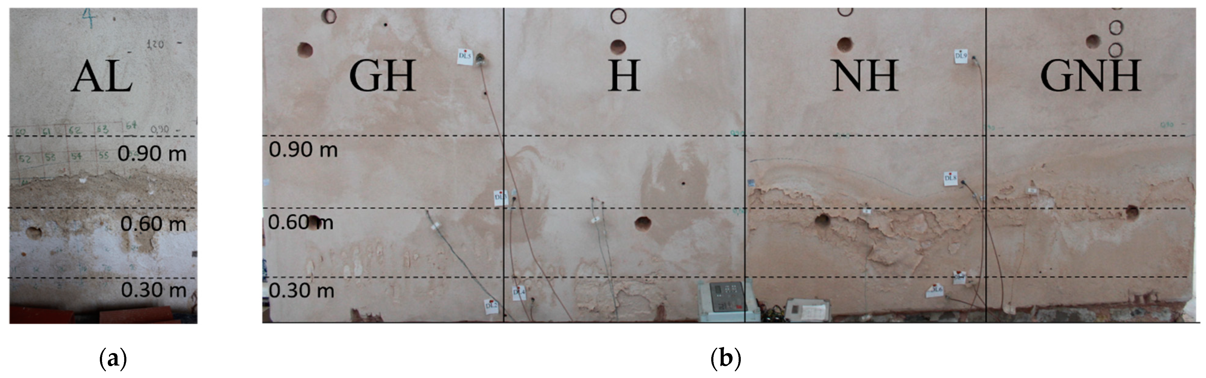
Salt damage was observed on the outer surface of the render systems and on the traditional lime render. The damage on the tested renders at the end of the second cycle (6 months drying), in terms of seriousness of damage, according to the ICCOMOS Glossary [21], and efflorescence quantity is presented in Figure 3.
The seconds cycle simulates a very aggressive stage with severe degradation for the render systems, especially GNH, NH and AL (Figure 3). The surface damage in each render system corresponds to the zones where moisture stains were noticed during the absorption stage in each cycle.
As seen from the results in Figure 3, AL, NH and GNH allow for salt transport towards the outer surface, where damage due to salt crystallization is observed in the form of generalized bulging of the surface and the loss of cohesion (sanding) on the zone that corresponds to the drying front. In contrast, GH prevents outer layer damage, appearing just in small zones on the outer surface near the grooves. In addition, comparing render systems GNH and NH, both without water repellent in the outer layer, it was concluded that, in this case, the presence of vertical grooves does not seem to influence the severity of surface damage at the end of the tests. Observing render systems GH and H (both with water repellent in the outer layer), the surface damage is reduced in the presence of water repellent and even more reduced when water repellent is associated with vertical grooves, as is the case in the GH render system, working in this last case as a salt-accumulating render system.
4.2. Pull-Off Tests
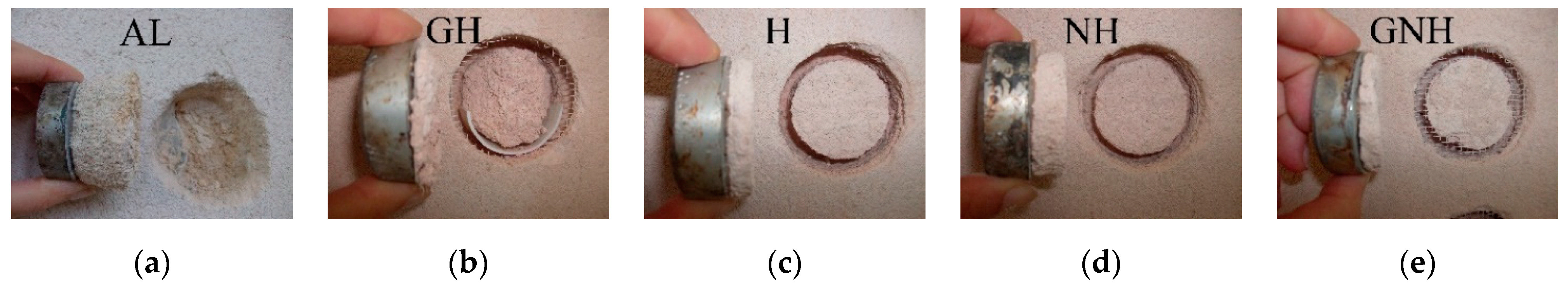
The pull-off tests were performed before absorption/drying tests. On AL, H and GNH render systems, the pull-off tests of some samples were broken during perforation. Figure 4 describes the type of rupture observations in the samples after the pull-off tests.
In the GH, H, H and GNH renders, adhesive ruptures were observed between the outer and base layers, meaning that the adherence to the masonry is higher than the adherence between render layers. In GH and GNH (renders with grooves in the base layer), it was not possible to determine a pull-off test value due to a low area connecting the base and outer layers in the testing zone, while in H and NH, the values were between 0 and 0.15 MPa and 0 and 0.10 MPa, respectively. In the AL render system, the adhesive rupture was observed between the render and the masonry, showing that the adherence to the substrate is lower than the adherence between render layers. The result obtained for pull-off test in AL render was found between 0 and 0.10 MPa, thus the adherence of this render to the masonry can be considered the lowest among the tested renders, as GH, H, NH and GNH have all the same base layer composition.
4.3. Materials Characterization
4.3.1. Chlorides Quantification and Distribution
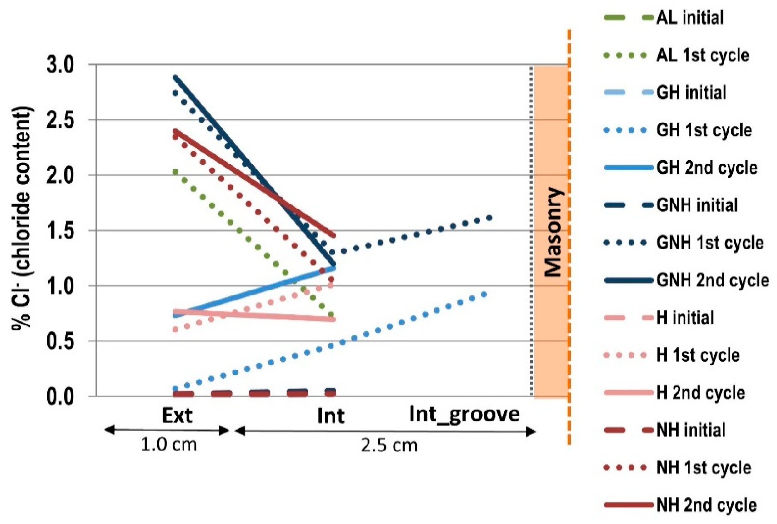
The quantification of chlorides was measured in the render systems (Figure 5) on samples removed by drilling at 0.30 m, to better understand the influence of the vertical grooves on the salt crystallization on the render’s outer and base layer, considering the different render systems. In AL, the chlorides were determined to allow for comparison with a traditional lime render. The chlorides content was measured on each render system. After the first and second cycles, chloride contents measured in the substrate and the render layers were uptakes from the solution, as the initial chloride content is assumed to be close to zero.
The vertical grooves in GH render system reduce the chloride content in the outer layer (Ext) at the end of the first cycle compared with the render system without groves H, although at the end of the second cycle, this is not so evident. In addition to the interpretation of the results from the chloride content, it was observed (Figure 3) that the evaporation front (where salt crystallization occurs and consequent damage appears) on the outer surface of GH render system (with grooves and water repellent) is localized in some vertical grooves, while the H render system (without grooves but with water repellent) is more generalized through the outer surface of the outer layer. As a result, the presence of vertical grooves associated with the presence of water repellent in the outer layer reduces the damage due to salt crystallization of outer surface on the render system GH.
On the base layer (Int) of the render system GH, formulated with brick powder, considerably higher salt accumulation was found compared with outer layer (Ext) formulated with water repellent; in this case, the base layer allows the transport of the salt solution until the vertical grooves where salts crystallize.
The base layer of render systems GH, H, NH and GNH shows higher chlorides content than base layer of AL as a result of the base layer formulation with brick powder that allows salt accumulation in its structure. The vertical grooves in base layer associated with water repellent in the outer layer (GH) induce salt crystallization in the vertical grooves (Int-groove). Comparing GH and GNH render systems the performance of the vertical grooves is highly influenced by the presence of water repellent in outer layer.
A higher difference in the chloride content was found in the NH and GNH render systems than in the GH and H systems in the outer and base layers, both in the first and second cycles.
Based on the results obtained by visual observations and chlorides quantification, the render system GH shows the best performance, that is, the least superficial damage. This render system was chosen to be the object of further research to test the durability and efficiency of the render system when applied on salt laden walls submitted to rising damp with soluble salts. The H render system (without vertical grooves and with water repellent in the outer layer) was also selected for comparison. Both renders show less damage due to salt crystallization when submitted to the severe action of salt laden water, compared with the other tested render systems. The type and location of crystallization was deeply investigated in the outer layer surface, in the middle of the outer layer, in the vertical grooves in GH render system and at the interface between the outer and base layers.
4.3.2. Scanning Electron Microscopy and Stereomicroscope Observations
- Vertical grooves in base layer: GH render system
Optical microscope observations in the vertical grooves of GH render system shows salt crystallization accumulation inside the grooves where evaporation is induced (Figure 6) on samples removed at 0.3 m and 0.6 m from the base of the masonry. Additionally, the presence of water repellent in the outer layer induces salt accumulation in the grooves, preventing salt solution transport to the outer layer.
The vertical grooves in the base layer allow salt crystallization inside them. They also allow ventilation and consequent evaporation of moisture. Due to this last effect, the reduction in moisture permanence in the substrate, referred in the literature [12,22] when water repellent is used in the outer layer, does not happen with the render system GH.
- Interface between base and outer layer: GH and H render systems
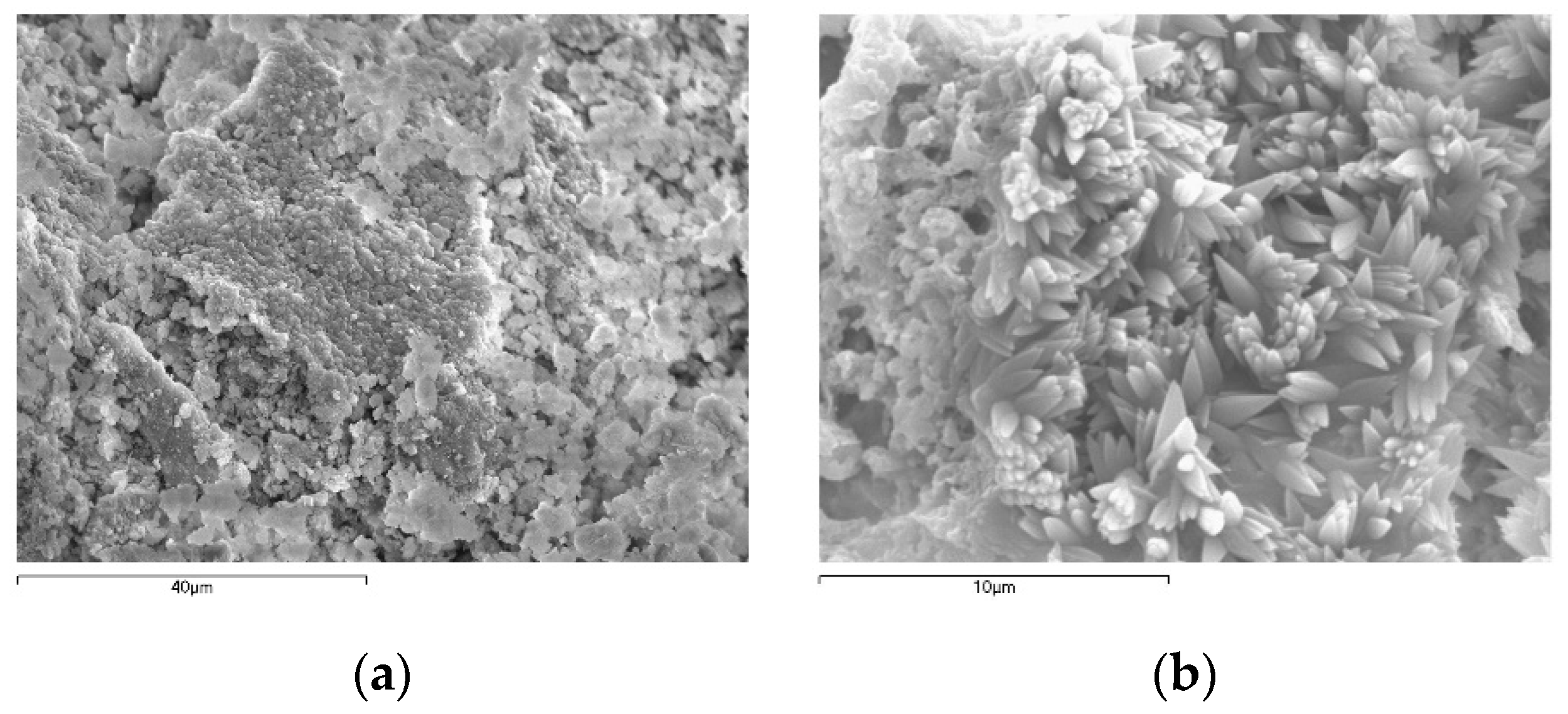
At the interface between the outer and base layer in the GH and H render systems, no NaCl crystallization was observed. There is a generalized presence of carbonate crystals denoting a well-carbonated paste (Figure 7). At the end of the second cycle, the detachment of the outer layer was not observed in none of the render systems (Figure 3).
- Outer layer: GH and H render systems
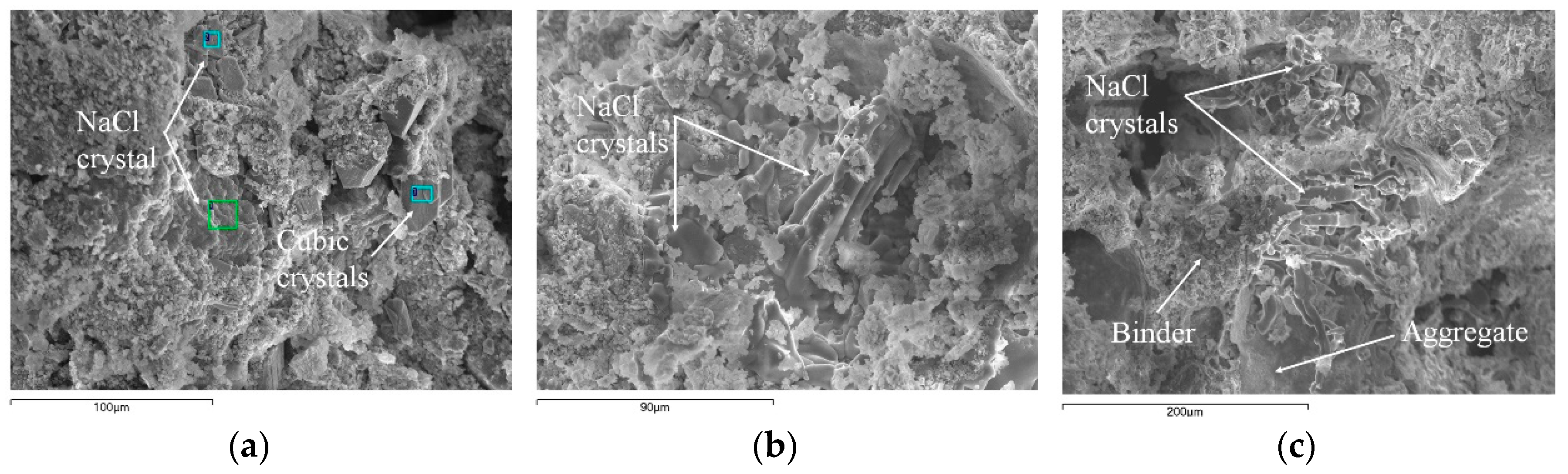
In the GH render system, at a depth of 3 mm from the surface, in a damaged zone, SEM observations (Figure 8a) show evidence of salt filling the pores of the binder matrix. Cubic crystals are present; this NaCl crystallization shape has already been referred in the literature [9] and has been associated to salt crystallization that results from salty solution intake. Around 5 mm from the surface of the outer layer of the H render system, the salts have crystallized in the form of needles at the binder/aggregate interface (in non-damaged zones) (Figure 8b), and later, they seem to have caused the de-cohesion of the binder (in damaged zones) (Figure 8c). The presence of NaCl with needle shape has already been referred in literature [9] due to repeated RH cycles (in this case, associated to repeated drying–absorption cycles) on a restoration plaster, leading later to the detachment of the aggregate particles. In the surface of the GH render system, in damaged zones, there seems to be a lower concentration of NaCl crystals than in H render system; in both render systems, a structure of salt and de-cohesive binder is present (Figure 8), confirming damage in localized zones. Analyzing these samples, a variety of morphologies of NaCl crystals can be observed with SEM.
5. Discussion of the Results
This paper explored the performance of this innovative render in terms of its effect on salt crystallization damage on a full-size masonry wall. The tested render systems behave very differently with respect to sodium chloride in terms of damage evolution, decay extent and deterioration patterns. In renders, salt crystallization generally induces a loss of material in the form of sanding, detachment and scaling.
The artificial ageing tests simulated the severe action of salt laden water in the real-size masonry, allowing the study of salt damage and testing the durability and efficiency of the render systems. Traditional lime render (AL) proved to have a rapid damage evolution and consequent early-stage failure. The GH render system shows the least superficial damage with localized scaling and efflorescence, followed by the H render system. The GNH and NH render systems show generalized damage through the outer surface, although to a lesser extent compared with the traditional AL render. The tested render systems show higher adherence to the substrate than the AL render. From the experiments performed, differentiated behaviors were observed on the various render systems, concerning the seriousness of damage, amount of efflorescence and location of salt accumulation. The influence of the varying factors is summarized as follows.
5.1. Influence of the Distance to the Ground
- The surface damage in each render system corresponds to the zones with moisture stains, noticed during the absorption stage in each cycle, mainly close to the drying front. The damage extent was different among render systems: Render systems without water repellent in the outer layer (GNH and NH) show generalized crumbling and sanding between 0.30 m and 0.90 m; Al (reference render system) shows even higher damage at the end of the tests; in the render systems with water repellent (GH and H) localized scaling and efflorescence, between 0.30 and 0.60 m, were observed; at 1.2 m, there is no evidence of salt crystallization in any of the studied render systems.
5.2. Influence of Render Composition
- Using a water repellent admixture in the outer layer of the render system with grooves (GH) transformed the salt-transporting render system GNH into a salt-accumulating render system.
- The existence of a water repellent admixture in the outer layer render systems (GH and GNH) reduced the surface salt damage compared with the other tested render systems. Considering the superficial outer layers salt damage on tested specimens, GH showed the best behavior.
- In the GH render system, at the interface between the base and outer layers, a significant crystallization of NaCl was not observed. The detachment of the outer layer was not observed in any tested render system.
- Brick powder additive in base layer (formulation F7) seems to increase salt transport preferentially in this layer (Figure 3) and, as a result, salt crystallization accumulation in the masonry is not expected. In addition, the base layer was observed to be very salt-resistant without damage and shows high strength noticed by the difficulty associated to sample removal.
- The base layer with brick powder as an additive promotes adequate adherence to the substrate and allows salt crystallization inside the pore system, as well as salt solution transport until the vertical grooves (in GH and GNH render systems) and to the outer surface where salt crystallization occurs as efflorescence (in GNH render system).
- The similar connected porosity found in the outer layer of GNH (F1h), NH (F1) and AL (Al) render systems (Table 1) can be a possible cause for the similar damage observed on their outer layer (although AL render a slightly higher) due to salt crystallization (disintegration, detachment, lacunae and efflorescence). The capillary coefficient of AL render can contribute this traditional render damage.
5.3. Influence of the Grooves
- The contribution of the grooves for the reduction of salt damage was observed in render system GH where damage was observed just in small zones on the outer surface near the grooves, while in the H render system, a greater damaged area on the outer surface was observed. In render systems, GNH and NH, the vertical grooves does not show great influence on surface damage, and both render systems show high and similar surface damage degree.
- The contribution of the grooves in the base layer and water repellent in the outer layer was observed to reduce salt damage in the render solution GH, where, at the end, only some damage was observed just in small zones in the outer surface near the grooves; in the H render system, a greater damage zone in the outer surface was observed compared with GH render system; in render systems GNH and NH, the vertical grooves have no significant influence on surface damage and both render systems show high surface salt damage.
- Hence, an important consequence of the grooves is to enable the use of a water-repellent on the outer layer and in this way reduce the damage on the surface, without risking the accumulation of salts within the substrate.
The contribution of the grooves to the reduction of salt damage was observed. The ventilated render system GH, compatible with historic masonries, was especially designed to allow for the accumulation of salts in the vertical grooves existent in the base layer, without creating damage in the external surface of the outer layer (with water repellent). The results from salt crystallization testing procedure on renders systems using a full-scale masonry wall are in accordance with the results obtained in a previous investigation [11] using small-scale specimens.
6. Conclusions
This work shows an extensive investigation on the development of a substitution render for salt laden historic masonries in built heritage by testing render systems on a full-scale masonry wall and evaluating their performance through salt crystallization tests.
Significant influence of the composition of the render system on the behavior of the wall concerning rising damp and salts crystallization was observed. From the outlined experimental results, on render systems tested in a full-scale masonry wall, the following conclusions can be drawn: (i) the vertical grooves increase the durability due to the high amount of salts crystallization inside them and do not allow crystallization on the outer surface when water repellent is used (comparing the render systems with and without grooves); (ii) the water repellent in the outer layer does not allow the salts crystallization on the outer surface (no visual de-characterization), when compared with the solution without water repellent in the outer layer; (iii) none of the tested render systems seems to contribute to salt crystallization inside the wall as salt solution transport was allowed through the render systems, mainly due to the presence of the F7 formulation (with brick powder) in the base layer; and (iv) the traditional lime render (AL) showed early-stage failure and was less durable than the tested renders systems (with brick powder in base layer formulation) under the same salt crystallization testing conditions.
This investigation has clearly established the positive influence of the grooves (in base layer) by allowing preferential salt crystallization within them, especially when water repellent is used in the outer layer. Hence, the grooves enable the use of a water-repellent on the outer layer and as consequence less damage is observed on the surface and does not seem to induce salt crystallization in the substrate. It was proven that the results from salt crystallization testing procedure on a full-scale masonry and on small-scale specimens from a previous work [11] are reliable and coherent.
The present work proved that ventilated render system GH (with vertical grooves and water repellent in the outer layer) is the most durable and efficient to be used as a substitution render on salt laden historic masonry walls, delaying the damage on the outer surface, without additional harm to the masonry.
Author Contributions
Conceptualization A.F. and R.V.; methodology, A.F.; validation, A.F., R.V. and A.V.; formal analysis, A.F., R.V. and A.V.; investigation, A.F.; writing—original draft preparation, A.F.; writing—review and editing, A.F., R.V. and A.V.; supervision, A.F., R.V. and A.V.; funding acquisition, A.F. All authors have read and agreed to the published version of the manuscript.
Funding
This research was supported by GeoBioTec Research Centre (UID/GEO/04035/2019 + UIDB/04035/2020), funded by Portuguese Foundation for Science and Technology (FCT), FEDER funds through the Operational Program Competitiveness Factors COMPETE and by national funds (OE), through FCT in the scope of the framework contract foreseen in the numbers 4, 5 and 6 of the article 23, of the Decree-Law 57/2016, of August 29, changed by Law 57/2017, of July 19 and grant number SFRH/BDE/33800/2009.
Institutional Review Board Statement
Not applicable.
Informed Consent Statement
Not applicable.
Data Availability Statement
Not applicable.
Acknowledgments
The experimental work described in this paper was conducted at the Wall Covering Unit (NRI) of National Laboratory for Civil Engineering (LNEC). Fradical Lda Company is gratefully acknowledged for proving the render materials, and for its contribution for systems conception and execution in the masonry wall. The authors wish to thank the technicians of NRI for their support on the execution of the tests and the technicians of Metallic Materials Unit (NMM) of LNEC for their help with the Scanning Electron Microscope observations.
Conflicts of Interest
The authors declare no conflict of interest.
References
- Veiga, M.R. Air lime mortars: What else do we need to know to apply them in conservation and rehabilitation interventions? A review. Constr. Build. Mater. 2018, 157, 132–140. [Google Scholar] [CrossRef]
- Veiga, M.R.; Silva, A.S. Mortars. In Woodhead Publishing Series in Civil and Structural Engineering, Long-Term Performance and Durability of Masonry Structures; Ghiassi, B., Lourenço, P.B., Eds.; Woodhead Publishing: Cambridge, UK, 2019; pp. 169–202. [Google Scholar] [CrossRef]
- Fragata, A.; Velosa, A.L.; Veiga, M.R. Salt crystallization in substitution renders for historical constructions. In Historic Mortars and RILEM TC 203-RHM Final Workshop HMC2010. In Proceedings of the 2nd Conference and of the Final Workshop of RILEM TC 203-RHM, Prague, Czech Republic, 22–14 September 2010; Válek, J., Groot, C., Hughes, J.J., Eds.; RILEM Publications S.A.R.L.: Paris, France, 2010; pp. 983–992. Available online: https://www.rilem.net/publication/publication/82?id_papier=3316 (accessed on 30 July 2021).
- Granneman, S.J.C.; Lubelli, B.; Hees, R.P.J. Mitigating salt damage in building materials by the use of crystallization modifiers—A review and outlook. J. Cult. Herit. 2019, 40, 183–194. [Google Scholar] [CrossRef]
- Scherer, G. Internal stress and cracking in stone and masonry. In Measuring, Monitoring and Modeling Concrete Properties; Konsta-Gdoutos, M.S., Ed.; Springer: Dordrecht, The Netherlands, 2006; pp. 633–641. [Google Scholar] [CrossRef]
- Fragata, A.; Ribeiro, J.; Candeias, C.; Velosa, A.; Rocha, F. Archaeological and Chemical Investigation on the High Imperial Mosaic Floor Mortars of the Domus Integrated in the Museum of Archaeology D. Diogo de Sousa, Braga, Portugal. Appl. Sci. 2021, 11, 8267. [Google Scholar] [CrossRef]
- Lubelli, B.; Cnudde, V.; Diaz-Goncalves, T.; Franzoni, E.; Hees, R.P.J.; Ioannou, I.; Menendez, B.; Nunes, C.; Siedel, H.; Stefanidou, M.; et al. Towards a more effective and reliable salt crystallization test for porous building materials: State of the art. Mater. Struct. 2018, 51, 55. [Google Scholar] [CrossRef]
- Fragata, A. Compatible Renders for Historical Masonries Submitted to the Severe Action of Water. Ph.D. Thesis, University of Aveiro, Aveiro, Portugal, 2013. Available online: https://ria.ua.pt/handle/10773/11678 (accessed on 30 July 2021).
- Lubelli, B. Sodium Chloride Damage to Porous Building Materials. Ph.D. Thesis, Delft University of Technology, Delft, The Netherlands, 2006. Available online: https://repository.tudelft.nl/islandora/object/uuid%3Ac8d72659-ca2f-4a82-aa5c-b4a39b6daaf8?collection=research (accessed on 30 July 2021).
- Veiga, M.R.; Velosa, A.L.; Magalhães, A.C. Experimental applications of mortars with pozzolanic additions: Characterization and performance evaluation. Constr. Build. Mater. 2009, 23, 318–327. [Google Scholar] [CrossRef]
- Fragata, A.; Veiga, M.R.; Velosa, A.L. Substitution ventilated render systems for historic masonry: Salt crystallization tests evaluation. Constr. Build. Mater. 2016, 102, 592–600. [Google Scholar] [CrossRef]
- Gonçalves, T. Salt Crystallization in Plastered or Rendered Walls. Ph.D. Thesis, Technical University of Lisbon, Lisbon, Portugal, 2007. [Google Scholar]
- Massari, G.; Massari, I. Damp Buildings, Old and New; ICCROM: Rome, Italy, 1993. [Google Scholar]
- Veiga, M.R.; Fragata, A.; Velosa, A.L.; Magalhães, A.C.; Margalha, G. Lime-Based Mortars: Viability for Use as Substitution Renders in Historical Buildings. Int. J. Archit. Herit. 2010, 4, 177–195. [Google Scholar] [CrossRef]
- Hees, R.P.J. Repair mortars for historic masonry. From problem to intervention: A decision process. RILEM TC 203-RHM: Repair mortars for historic masonry. Mater. Struct. 2012, 45, 1295–1302. [Google Scholar] [CrossRef]
- Auger, F. World Limestone Decay under Marine Spray and Conditions. In The Conservation of Monuments in the Mediterranean Basin. In Proceedings of the 1st International Symposium on the Influence of Coastal Environment and Salt Spray on Limestone and Marble, Bari, Italy, 7–10 June 1989; Fulvio, Z., Ed.; Grafo: Brescia, Italy, 1990; pp. 65–69. [Google Scholar]
- Vilhena, A.; Matias, L.; Magalhães, A.; Santos, P.; Veiga, R. Thermographic Analysis to Visualize the Saline Water Absorption and the Drying of a Stone Masonry Wallet—Capillarity Test; LNEC: I&D Edifícios, NRI Report 241/2007; LNEC: Lisbon, Portugal, 2007. (In Portuguese) [Google Scholar]
- NP EN 1015-12:2016. Methods of Test for Mortar for Masonry—Part 12: Determination of Adhesive Strength of Hardened Rendering and Plastering Mortars on Substrates; European Committee for Standardization: Brussels, Belgium, 2016. [Google Scholar]
- Veiga, M.R.; Aguiar, J.; Silva, A.S.; Carvalho, F. CED 9—Conservation and Renovation of wall Renders from Old Buildings, 1st ed.; LNEC: Lisbon, Portugal, 2004; p. 126. (In Portuguese) [Google Scholar]
- NT Build 208. Concrete Hardened: Chloride Content, 3rd ed.; Nordtest: Lisbon, Finland, 1996. [Google Scholar]
- Vergès-Belmin, V. (Ed.) Illustrated Glossary on Stone Deterioration Patterns; Monuments and Sites XV; ICOMOS: Paris, France, 2008. [Google Scholar]
- Petković, J.; Huinink, H.P.; Pel, L.; Kopinga, K.; Hees, R.P.J. Moisture and salt transport in three-layer plaster/substrate systems. Constr. Build. Mater. 2010, 24, 118–127. [Google Scholar] [CrossRef]
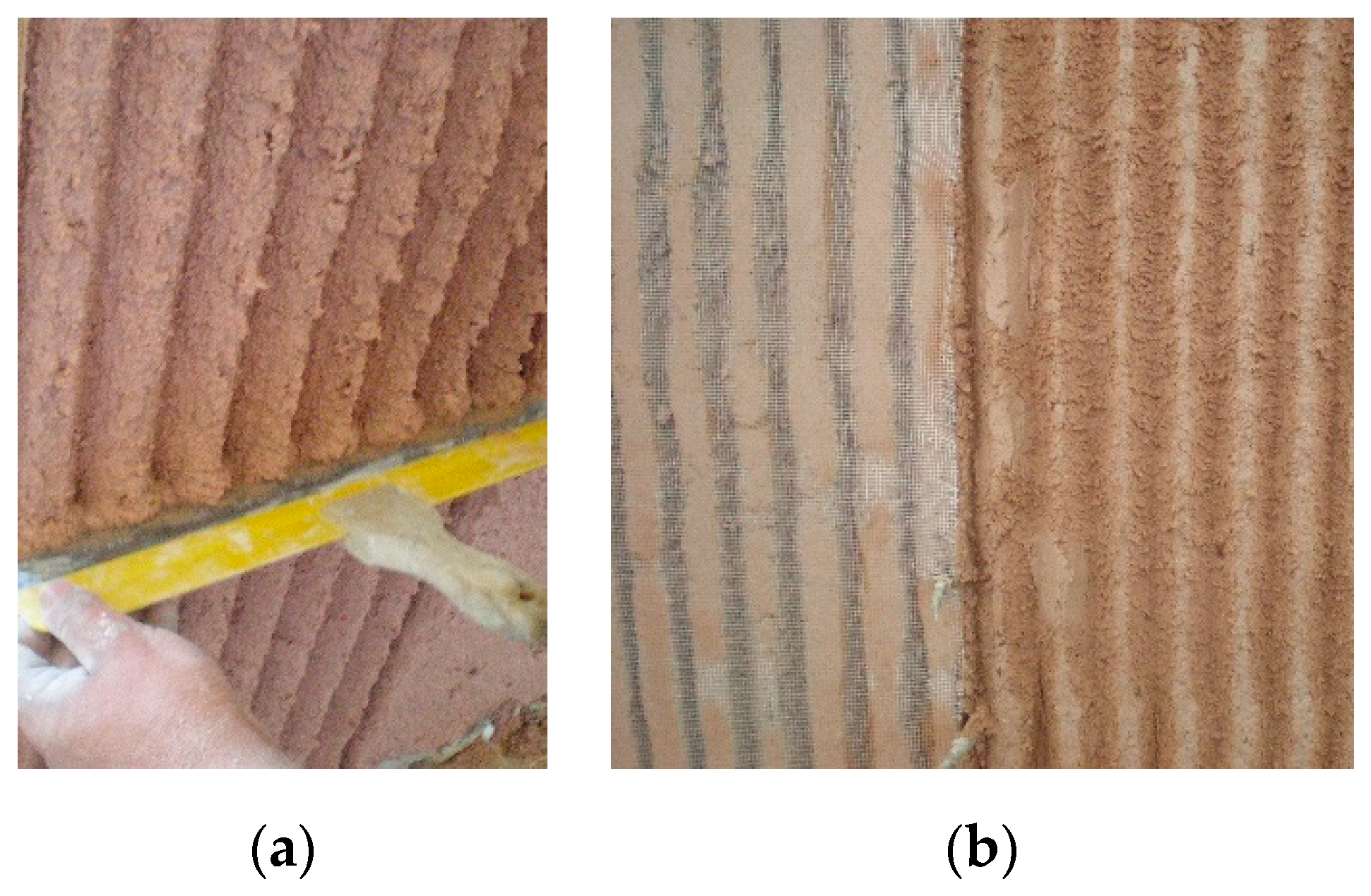
Figure 1.
Render systems GH and GNH base layer: (a) grooves execution; (b) grid application.

Figure 2.
Schematic representation of the render systems (GH, H, NH and GNH) in the full-scale masonry wall—upper view.
Figure 2.
Schematic representation of the render systems (GH, H, NH and GNH) in the full-scale masonry wall—upper view.

Figure 3.
Damage observation [ and efflorescence quantity on the renders of the full-scale masonry wall after 6 months drying on the second cycle: (a) traditional lime render: AL (until 0.80 m): very much efflorescence, very serious damage—generalized sanding and crumbling (b) render systems: GH (localized between 0.20 and 0.40 m: some efflorescence, moderate damage—loss of cohesion; H (until 0.40 m): much efflorescence, intense damage—delamination/scaling; NH (until 0.70 m): very much efflorescence, serious damage—sanding and generalized delamination/scaling; GNH (until 0.70 m): very much efflorescence, serious damage—sanding and generalized delamination/scaling.

Figure 4.
Pull-off tests on render systems on the full-scale masonry wall: (a) AL—Adhesive rupture between render and the support (values between 0 and 0.10 MPa); (b) GH—Adhesive rupture between outer and base layer (in the glass fiber mesh) (values not determined—n.d.); (c) H—Adhesive rupture between outer and base layer (values between 0 and 0.15 MPa); (d) NH—Adhesive rupture between outer and base layer (values between 0 and 0.10 MPa); (e) GNH—Adhesive rupture between outer and base layer (in the glass fiber mesh) (values not determined—n.d.).

Figure 5.
Results of chloride content in render systems GH, H, GNH, NH and AL in 1st and 2nd cycles, at 0.30 m of height.
Figure 5.
Results of chloride content in render systems GH, H, GNH, NH and AL in 1st and 2nd cycles, at 0.30 m of height.

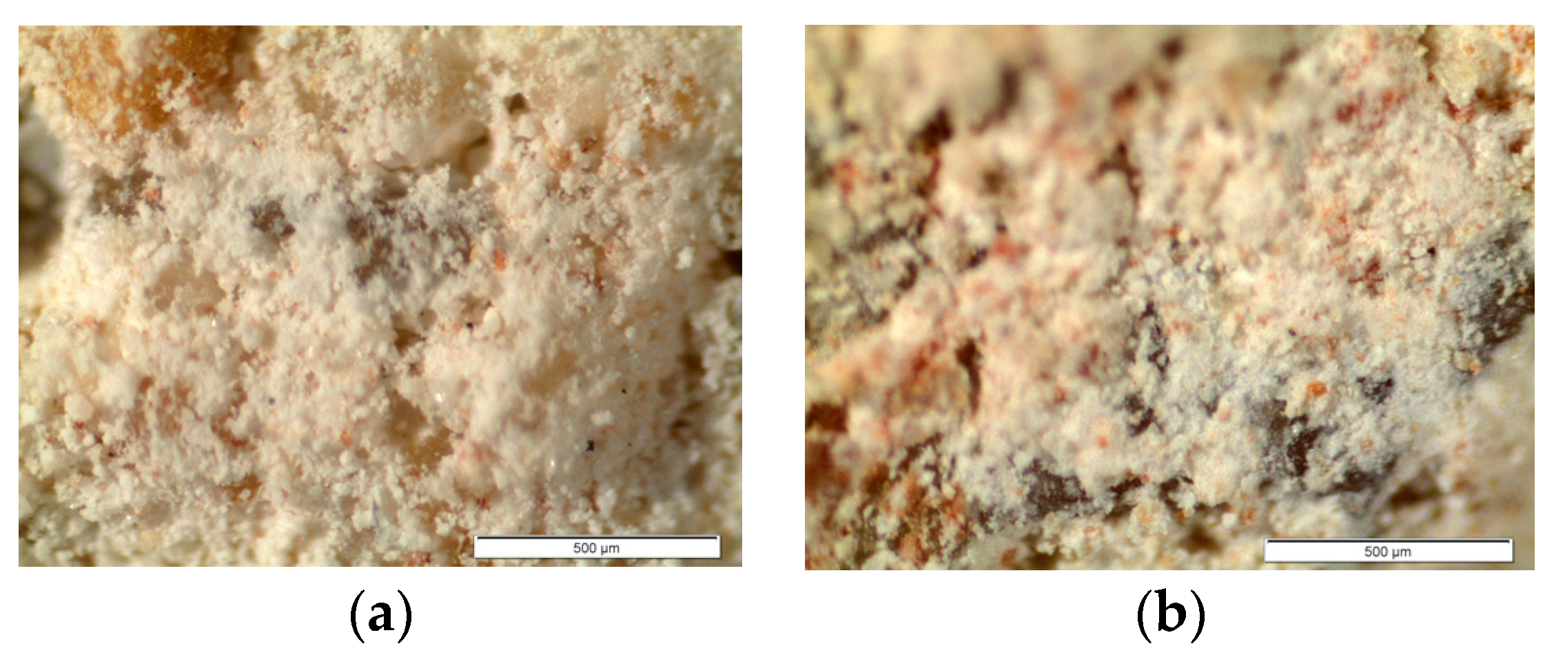
Figure 6.
Optical microscope observations of GH render systems inside the vertical grooves at the end of the 2nd dissolution/crystallization cycle (magnification ×70; scale bar 500 µm): (a) at 0.30 m—crystallization as “hair crystals and dense crust” (pulverulent appearance); (b) at 0.60 m—generalized crystallization.

Figure 7.
SEM photograph of the interface between outer and base layers: (a) (magnification ×1500) in GH, carbonate crystals (in damaged zone); (b) (magnification ×6000) in H render system not so much carbonation is observed, the carbonate crystals seem like flowers (in non-damaged zone).
Figure 7.
SEM photograph of the interface between outer and base layers: (a) (magnification ×1500) in GH, carbonate crystals (in damaged zone); (b) (magnification ×6000) in H render system not so much carbonation is observed, the carbonate crystals seem like flowers (in non-damaged zone).

Figure 8.
SEM photograph of outer layer (3/5 mm from the surface): (a) GH render system (magnification ×500): NaCl and carbonate crystals disperse in the middle of the binder (in damaged zone); (b) H render system (in damaged zone) (magnification ×650): NaCl crystals dispersed in the middle of the binder (damage zone); (c) H base layer (magnification ×300): NaCl crystals in voids; seems that the aggregates have drop down from the voids (in non-damaged zone).


Table 1.
Render layers mortars composition and physical and mechanical characteristics.
| Render Layer | Formulation | Volumetric Dosage | Density (kg/m3) | Pc (%) | C (Kg/m2.min1/2) | Sd (m) | Rt (MPa) | Rc (MPa) |
|---|---|---|---|---|---|---|---|---|
| Al | Air lime; siliceous sand | 1:3 | 1720 * | 15.9 | 6.50 * | 0.06 * | - | - |
| F1 | Lime putty; artificial pozzolanic addition; mixture of fine and medium size calcareous sand (1 + 3) | 1:0.2:(1 + 3) | 1590 | 19.1 | 1.26 | 0.07 | 0.41 | 0.78 |
| F1h | Lime putty with water repellent additive in the putty; artificial pozzolanic addition; mixture of fine and medium size calcareous sand (1 + 3) | 1:0.2:(1 + 3) | 1620 | 17.3 | 0.06 | 0.08 | 0.4 | 1.3 |
| F7 | Lime putty; artificial pozzolanic addition; brick powder; medium size calcareous sand | 1:0.5:(1 + 3) | 1580 | 24.7 | 1.41 | 0.07 | 0.52 | 1.81 |
C—Capillary coefficient between 0 and 30 min at 90 days; Sd—Air thickness of equivalent diffusion to 0.10 m of mortar; Rt—Flexural stress 90 days (MPa); Rc—Compressive stress as 90 day (MPa); Pc—connected porosity. * Vilhena et al. 2007 [17].
Table 2.
Render system constitutions.
| Render System | Base Layer (2 cm) | Vertical Grooves | Layer between Base and Outer Layer | Outer Layer (1.5 cm) |
|---|---|---|---|---|
| AL | Al | No | - | Al |
| GH | F7 | Yes | Composed by lime putty and fine sand | F1h |
| GNH | F7 | Yes | - | F1 |
| H | F7 | No | - | F1h |
| NH | F7 | No | - | F1 |
Publisher’s Note: MDPI stays neutral with regard to jurisdictional claims in published maps and institutional affiliations. |
© 2021 by the authors. Licensee MDPI, Basel, Switzerland. This article is an open access article distributed under the terms and conditions of the Creative Commons Attribution (CC BY) license (https://creativecommons.org/licenses/by/4.0/).
Share and Cite
MDPI and ACS Style
Fragata, A.; Veiga, R.; Velosa, A. Performance of a Salt-Accumulating Substitution Lime Render for Salt Laden Historic Masonry Walls. Heritage 2021, 4, 3879-3891. https://0-doi-org.brum.beds.ac.uk/10.3390/heritage4040212
AMA Style
Fragata A, Veiga R, Velosa A. Performance of a Salt-Accumulating Substitution Lime Render for Salt Laden Historic Masonry Walls. Heritage. 2021; 4(4):3879-3891. https://0-doi-org.brum.beds.ac.uk/10.3390/heritage4040212
Chicago/Turabian StyleFragata, Ana, Rosário Veiga, and Ana Velosa. 2021. "Performance of a Salt-Accumulating Substitution Lime Render for Salt Laden Historic Masonry Walls" Heritage 4, no. 4: 3879-3891. https://0-doi-org.brum.beds.ac.uk/10.3390/heritage4040212