1. Introduction
In Italy, residential buildings are characterized by different construction types. In particular, the Italian historic centres are often characterized by a large presence of masonry buildings. Over time and due to technological progress, the urbanized areas have expanded their borders, and the new residential structures were built mostly using reinforced concrete as the basic material.
This paper focuses on masonry buildings, which represent the most widespread construction technology not only in Italy but all over the world, whose erections were also made several centuries ago. The masonry type varies according to the geographical area; in fact, the choice of materials was mainly influenced by the in situ availability to minimize the transport costs.
By analysing the masonry from a mechanical point of view, it is possible to observe that it is an inhomogeneous, anisotropic and elastic material. It has a good compressive strength but a poor tensile one. Therefore, considering that masonry walls are also stressed under tensile actions under earthquakes, it is always very important to assess the seismic vulnerability of existing masonry buildings in order to foresee and limit their seismic damages. Indeed, the usual poor mechanical characteristics of masonry do not help the structures against an earthquake, which could be damaged even if subjected to low seismic excitation [
1,
2,
3,
4,
5,
6]. In addition, these kinds of buildings were built in most cases in historical periods when no seismic design was required. Finally, it is necessary to evaluate both the global and local behaviour of masonry structures. In fact, during a seismic event, firstly, local collapse mechanisms can be activated, such as the total or partial overturning of facades [
7,
8,
9] and, secondly, global mechanisms involving the whole masonry apparatus can occur when good connections among walls and between walls and floors are detected.
In order to reduce seismic vulnerability and to make the buildings seismic-resistant structures, many retrofitting techniques have been designed over the time, according to the specific interventions [
10,
11,
12,
13,
14,
15] (global or local). Many effective, but invasive, traditional techniques [
16,
17,
18] have been overtaken by technological progress, especially after the introduction of FRP (Fibre-Reinforced Polymers) materials [
19,
20,
21,
22,
23].
Generally, in past applications, the seismic retrofit interventions were generally decoupled from those of energy modernization. In recent decades, reducing energy consumption has become an indispensable attitude for two fundamental and closely linked reasons: limiting the depletion of fossil fuels and reducing pollution by combating climate change. Therefore, integrated designs aimed to improve the buildings from both energy and seismic viewpoints have been developed [
24,
25,
26]. This combined design approach is also used in this paper, where the retrofitting and upgrading of the ecologic-seismic system represented by the novel seismic coat produced by the Italian company DUO System is proposed and presented. It is an anti-seismic external coating composed of CFS (Cold Formed Steel) frames on which OSB (Oriented Strand Board) panels are applied to act as a seismic shear wall. Insulating material is inserted between the CFS structure and the OSB panels in order to have an energetic benefit used to improve the building’s thermal dispersions through a decrease of 70% to 90% of its thermal transmittance value. From a seismic point of view, the DUO system improves the masonry structure both globally, allowing to attain at least the seismic upgrading of the construction if appropriately connected to the foundation, and locally, preventing the perimetral wall from overturning. Furthermore, other than for masonry buildings, this system is also suitable for RC ones. Thanks to its versatility and the combined seismic and thermal improvement, the DUO system is an ideal solution for the government initiatives that provide financial benefits aimed at improving existing structures. One example is the current Superbonus 110% financial measure provided by the Italian Relaunch Decree (law 19 May 2020, n.34) [
27], which raises the deduction rate for expenses incurred to 110% for specific interventions, including those aimed at seismic and energy efficiency. The deduction was originally due to expenses incurred from 1 July 2020 to 31 December 2021, but as a result of subsequent regulatory changes (law 30 December 2020, n.178—budget law 2021 and, lastly, decree law 6 May 2021, 59), the 110% Superbonus applies to expenses incurred by 2022 or 2023, depending on the type of buildings considered (public or private).
The case study is a masonry building located in the municipality of Torre Annunziata, in the district of Naples, Italy. The state of conservation of the building is poor, and some structural problems are detected. For this reason, the building is unusable and is not actually occupied by people. In order to make the structure usable again, the seismic upgrading of the structure through the use of the DUO system seismic coating is designed. Moreover, in order to achieve a satisfactory level of safety, in addition to the seismic coating, other intervention techniques, such as the replacement of existing floors, are proposed.
2. The Case Study
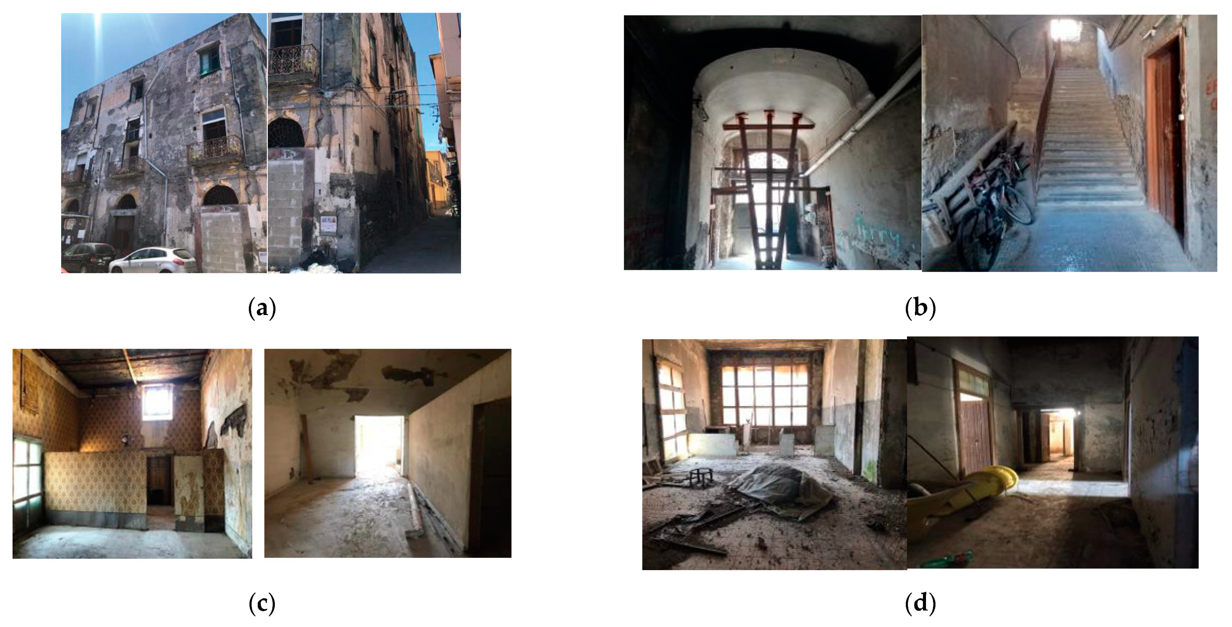
The case study is a masonry building located in the municipality of Torre Annunziata, a city in the district of Naples (Italy). It was built in 1758 and it was used by the Royal Arms Factory founded by Charles of Bourbon. This building, which was probably used as a warehouse by the Royal Weapons Factory, was developed on two vaulted floors. The building maintained this function until 1857. Later on, it changed its use and was subjected to a vertical addition with the erection of a third floor characterized by a slightly different wall texture and technology of floors and roof in comparison to the other levels. Therefore, the structure was erected in two different historical periods. First, the ground and first floors were built with the same masonry type. The orthogonal walls are well clamped to each other and have no discontinuities. The same behaviour was detected for masonry walls of the second floor, which was built in a more recent time.
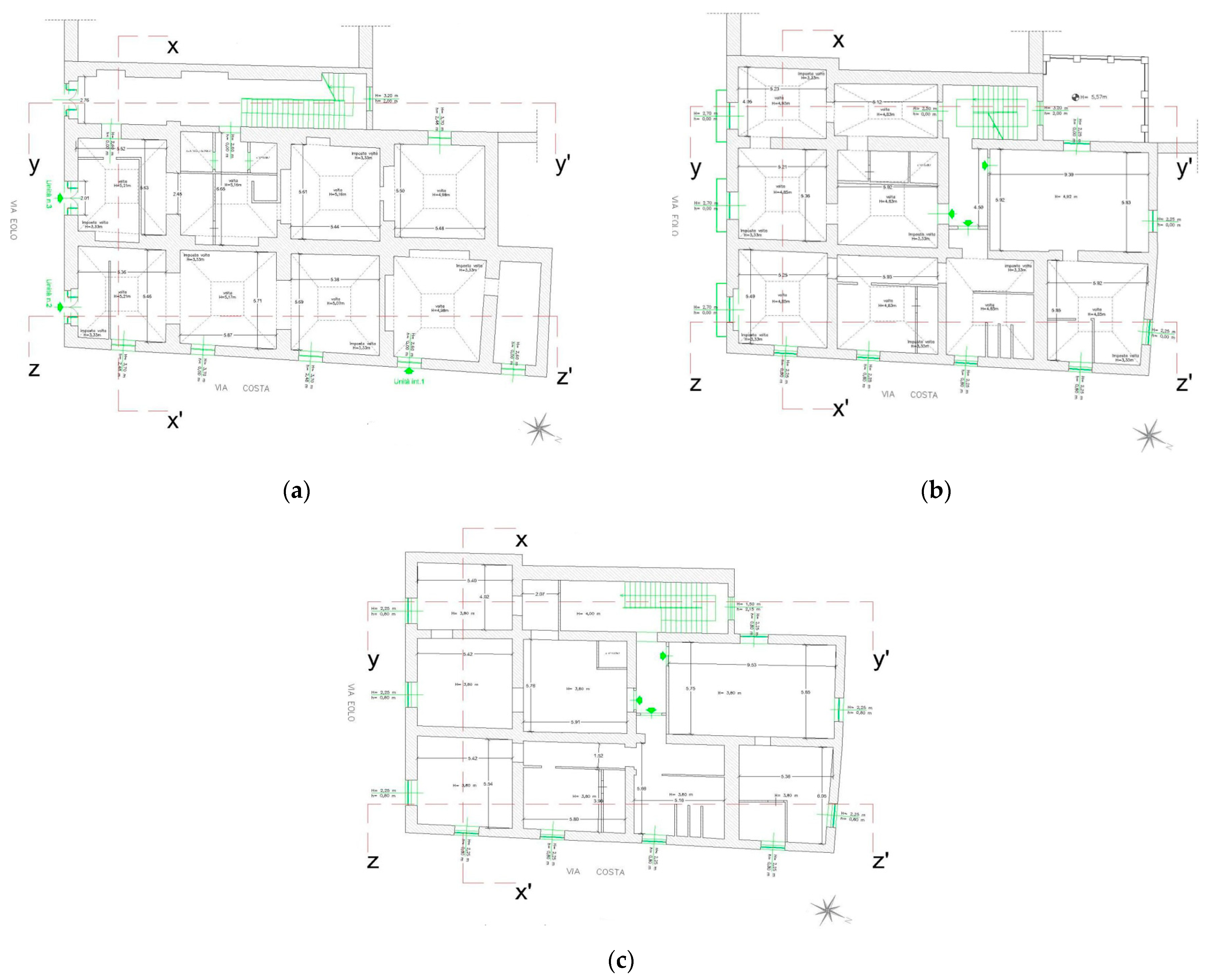
The building plan configuration has an irregular shape inscribed in a rectangle measuring 29.5 × 16.72 m actually used for residential purpose and developed on an overall height of 15.07 m. The building presents different floor types: the first and second floors are made up of vaulted floors, the second ones and roof are composed by the alternation vaults and wooden floors, the latter in some cases reinforced by steel profiles.
Figure 1 shows the photographic survey of the construction, while the plan configuration layouts, external views and sections are depicted in
Figure 2,
Figure 3 and
Figure 4, respectively.
The examined building is an optimal case for a seismic-energy integrated retrofit study. It is a historic building having a poor conservation status. Due to its historical value, the demolition and reconstruction of a new structure is not feasible. Furthermore, there are no strict provisions from local authorities that can prohibit certain upgrading techniques. The only requirement concerns the conservation of the masonry vaults, which have historical value. Therefore, it is possible to use the considered seismic upgrading techniques aimed at reinforcing the existing walls and floors.
3. Mechanical Characterization of Materials
The building masonry is characterized by stones made of tuff, which is a material obtained from the cutting of volcanic rocks, whose use is widespread in the geographical area under investigation.
Several on-site tests are carried out to determine the mechanical characteristics of masonry. First of all, flat jack tests are performed. This type of test is regulated by the American Society for Testing and Materials (ASTM) by means of the C1196 [
28] and C1197 [
29] standards. In order to carry out these tests, one or two horizontal cuts, corresponding to the location of mortar layers, are executed. Three different tests can be executed:
- -
A single jack test in order to identify the stress values acting on masonry. The on-site stress is:
where p is the pressure value measured by the hydraulic pump pressure; K
a is a coefficient taking into account the ratio between the jack surface and the cut one; K
m is a coefficient considering the jack stiffness.
- -
Double jacks test to determine the compressive strength and the elastic modulus of masonry. Pressing the two jacks simultaneously, a state of uniaxial tensile on the portion of masonry between them is generated, thus reproducing a test under conditions similar to those of the conventional uniaxial experiment. The pressure applied by the two jacks on the masonry is calculated as follows:
where p is the pressure value recorded by the pressure of the hydraulic pump; K
m is the average value of the two calibration coefficients of the jacks; A
m is the jack area; A
t is the average value of the two cutting areas.
The vertical elastic modulus is obtained by the following equation:
where ε
v is the deformation measured at the median stress axis between the two jacks.
- -
A test with the application of two vertical jacks and a horizontal one, in order to estimate the shear resistance of the masonry.
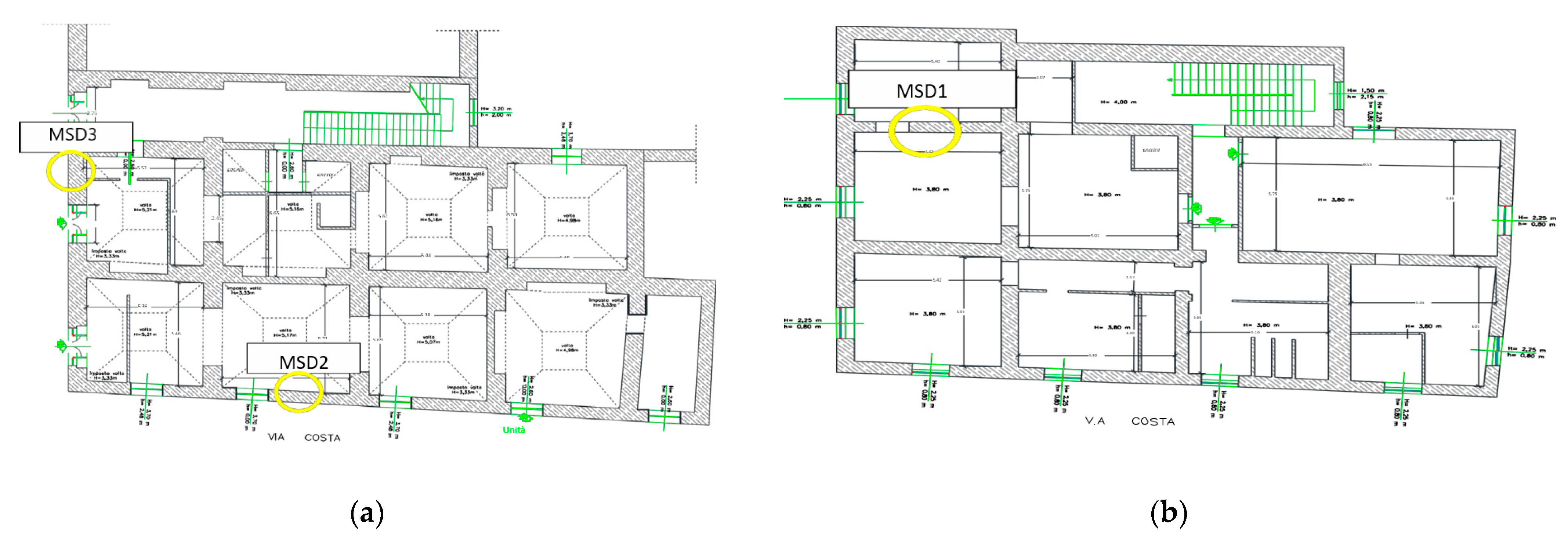
Three on-site flat jack tests followed by double jack ones (named MSD1, MSD2 and MSD3) are conducted by the CSW Engineering s.r.l. company(Salerno, Italy). The test equipment consists of a semi-circular jack having diameter of 34.5 cm and thickness of 4 mm, a low-flow manual hydraulic pump, an AEP precision transducer and a precision mechanical deformometer having base of 300 mm. The positions of performed tests are illustrated in
Figure 5.
Table 1 shows the test data, while the on-site test results are visible in
Table 2.
According to the Italian standards [
30,
31], a confidence factor, understood as an indicator of the knowledge level reached, is used to reduce the values of the mechanical parameters of the materials. In this work, an intermediate level, named LC2, is attained. This level is reached because the historical-critical analysis, the complete geometric survey and extensive material investigations are carried out. Therefore, the corresponding confidence factor, FC, is equal to 1.2.
As prescribed by Italian standard, the resistances to be adopted for the analysis refer to the average values of the intervals found in Table C8.5.I [
31]. In addition, for the elastic modulus, the average value of the interval showed in the same table must be adopted. So, based on the standard provisions, a compressive strength of 1.8 MPa and an elastic modulus of 1080 MPa should be considered for masonry mechanical characterization.
As it is seen from
Table 2, the values obtained from the on-site tests are lower than those suggested by [
31]. Therefore, the minimum values of experimental tests, represented by a compressive strength of 0.82 MPa and an elastic modulus of 840 MPa (see
Table 2), are adopted as material features.
4. Numerical Model of the Case Study
The 3D model of the case study is implemented by using the SAP2000 software ver. 20.0.0. The equivalent frame model approach, which is used in the scientific literature [
32,
33,
34,
35,
36,
37,
38,
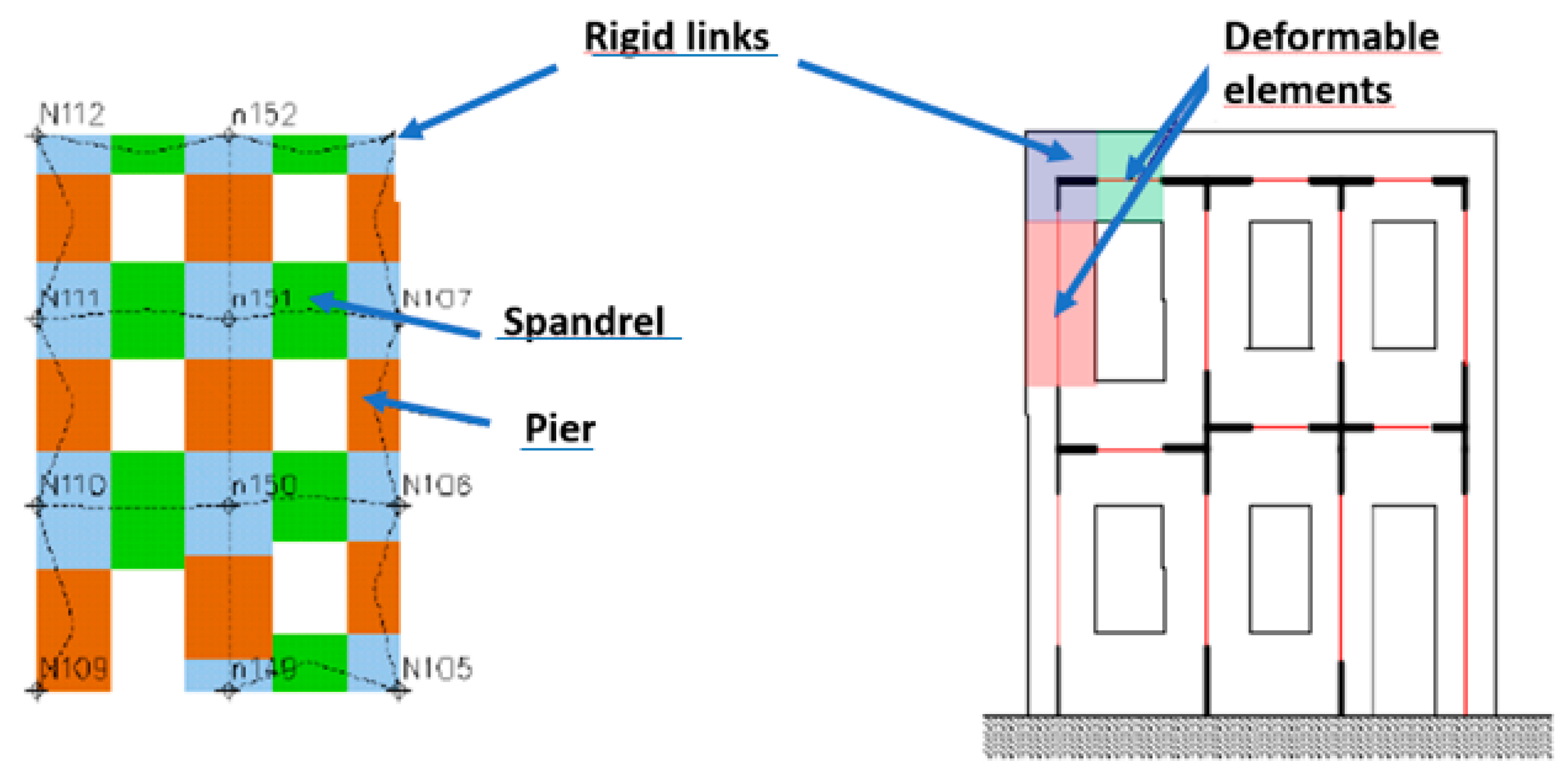
39], is herein adopted as a possible technique for masonry modelling. This analysis approach is the result of the study of recurrent crack patterns characterizing existing buildings. In fact, from the analysis of the damage mechanisms of masonry structures, it emerged that lesions are concentrated in some weaker areas of the walls, while other areas, schematised as rigid links, remain substantially intact. In particular, weak masonry parts are spandrels and piers, which are one-dimensional elements with deformability under axial and shear stresses. These elements are connected to each other at their ends by nodal panels, which represent the masonry parts undeformed under seismic actions and schematized as rigid links (
Figure 6). Spandrels are represented by frame elements with a horizontal axis. It is assumed that the pier deformable part corresponds approximately to the opening length, and the remaining parts at the ends are modelled with infinitely rigid elements.
In the SAP 2000 software model, the first step is to discretize the wall into spandrels and piers, which are modelled as beam elements. Each element is represented by its barycentric axis, delimited by nodes positioned at the floor level. In particular, each pier consists of a deformable part with finite resistance and two infinitely rigid parts at the extremities are positioned. The effective height or the deformable one of piers can be defined according to the following expression [
40]:
where 𝐻
𝑒𝑓𝑓 is the piers deformable height;
H is the inter-floor height;
D is the masonry wall width; and
h′ is the wall height.
The 3D equivalent frame is fixed to the base to simulate the presence of the superficial foundations.
Figure 7 shows the building’s numerical model setup with the used software.
As far as the plastic hinges are concerned, in the equivalent frame model, it is assumed that piers have an elastic-plastic behaviour with the following collapse mechanisms:
- -
Failure due to bending-overturning caused when the ultimate bending-moment value is reached;
- -
Shear failure with diagonal crack following the achievement of the shear ultimate value;
- -
Failure due to shear-sliding: This failure occurs in the case of horizontal cracks due to the poor mechanical quality of the mortar joints or in the case of reduced vertical load at the masonry top part.
In the absence of tensile-resistant elements, such as reinforced concrete tie-beams or steel tie-rods, the spandrels’ resistant contribution in terms of both tensile actions and bending moment is neglected. In such conditions, the masonry walls are not coupled and have a shelf behaviour. In the opposite case, spandrels and piers are jointly connected to make a frame.
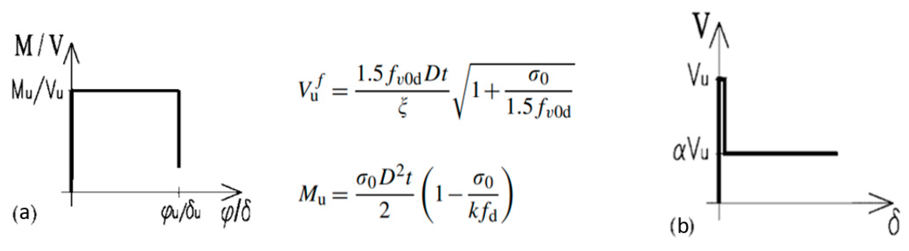
Figure 8 shows the behaviour of plastic hinges [
41] having ultimate bending and shear drifts equal to 0.8% and 0.4%, respectively.
The non-linear analysis results of the un-retrofitted structure in terms of the force–displacement curves obtained from the SAP2000 software are depicted in
Figure 9.
5. Seismic Upgrading
This work is aimed to improve the actual building behaviour under seismic actions. To this purpose, seismic interventions by applying both traditional and innovative solutions are considered, as shown in the next sections.
5.1. Steel Tie-Beams
Tie-beams create a continuous connection between floors and/or the roof and the walls on which they insist. In addition, they allow for a containment action against thrusts of the roof-inclined beams on the walls to distribute vertical loads in static conditions, to connect orthogonal walls each to other and to favour the building’s box-like behaviour.
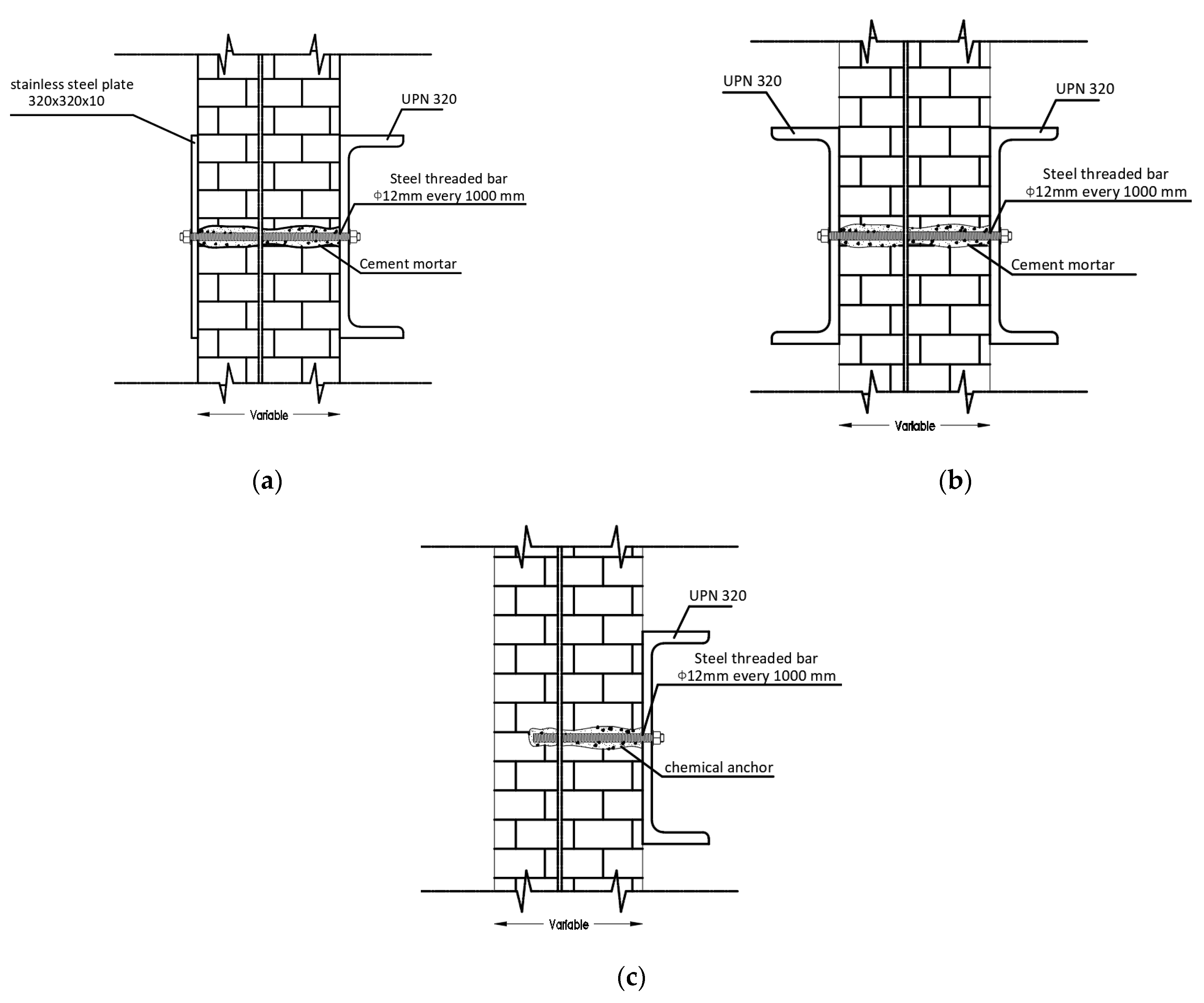
In this work, external steel (S355 type) tie-beams are designed. In particular, three different configurations depending on the wall position, namely, on the perimeter (
Figure 10a), internal (
Figure 10b) or in aggregate with other structural units (
Figure 10c), are considered.
5.2. Replacement of Floors
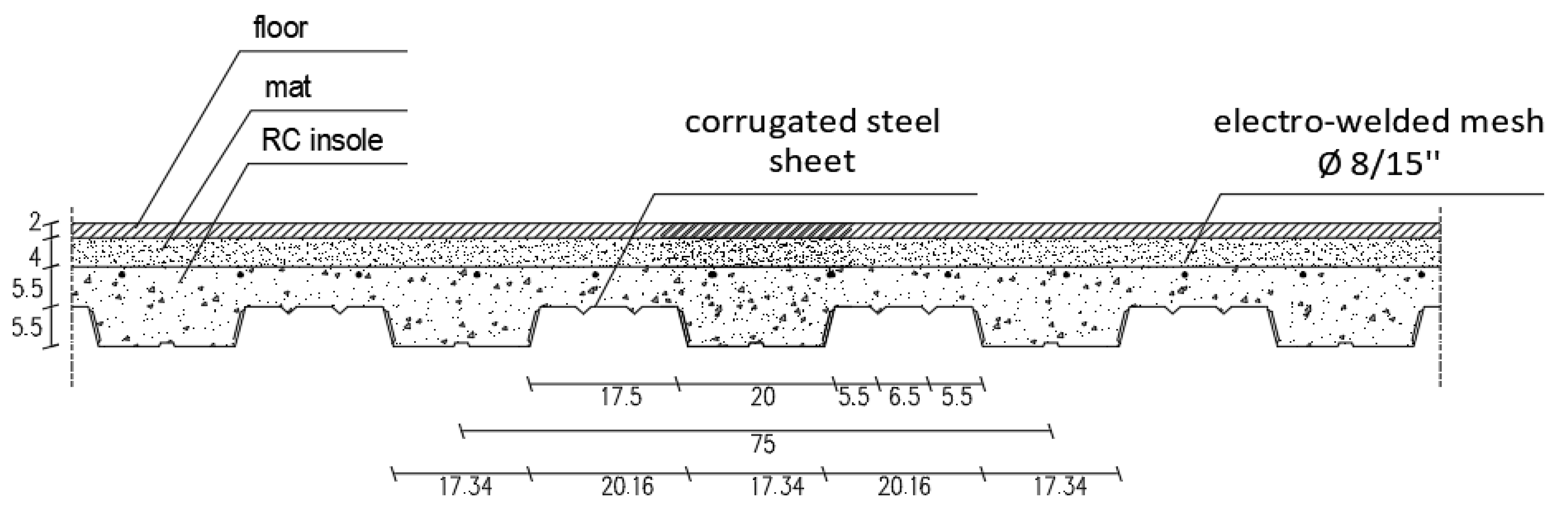
The role of the floors is to transfer both vertical and horizontal actions to the walls. With reference to seismic forces, if rigid floors are present, the actions are transferred uniformly to the masonry walls. On the other hand, deformable floors transfer the horizontal loads to the load-bearing elements (walls) in a non-uniform way. In the case under study, to obtain a uniform distribution of the horizontal loads on the load-bearing elements, it is necessary to have an RC slab with a thickness of at least five cm. For this reason, all existing (deformable) wooden floors are replaced with mixed steel-concrete ones, as illustrated in
Figure 11. IPE 270 steel beams made of S275 steel are placed each 2.5 m as a supporting structure of the mixed steel–concrete floor. Steel beams are connected with bolted joints to the steel tie-beams depicted in
Figure 10.
As for the existing vaults, the bottom part is kept unaltered. Above, an emptying of the filling material is performed. Afterwards, reinforcement of the vault at the extrados is made using the innovative technique of a highly resistant galvanized steel fibre mesh impregnated with a cementitious matrix. The filling of the vault at extrados to have a horizontal floor is made with low specific weight material, such as expanded clay.
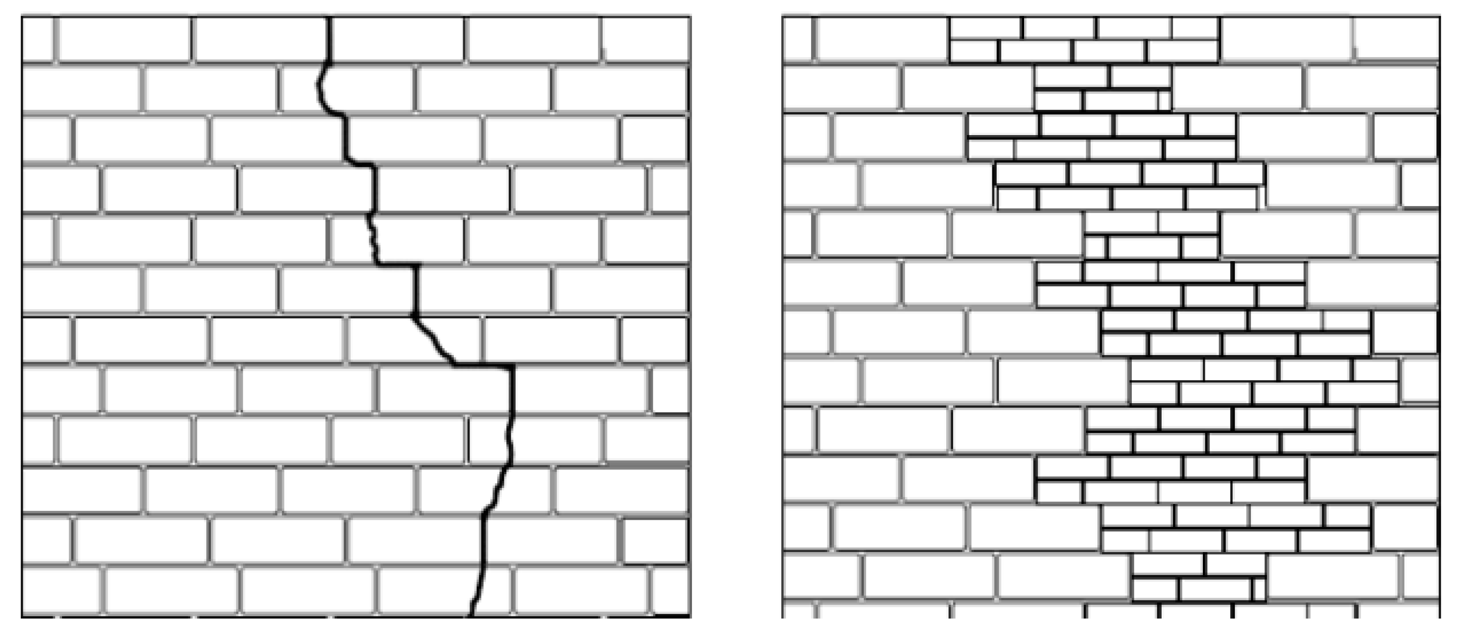
5.3. Reinforcement of Masonry Walls Using the “Scuci and Cuci” Technique
This technique consists of the local demolition of the damaged wall parts and of the subsequent reconstruction of the masonry apparatus (
Figure 12). This technique requires caution during the demolition phase, taking care to avoid shocks and vibrations and providing protective devices on the masonry to be replaced. The wall facing is washed with low pressure water, and finally, the previously removed wall segments are reconstructed using solid bricks laid with mortar having physical-mechanical characteristics similar to the pre-existing one. The solid bricks will be clamped on both sides to the old masonry, taking care to leave space between the new and old masonry for the insertion of special wedges.
For this intervention, for the sake of the conservation of the masonry fabric, it has been decided to use a new tuff block masonry with M15 mortar.
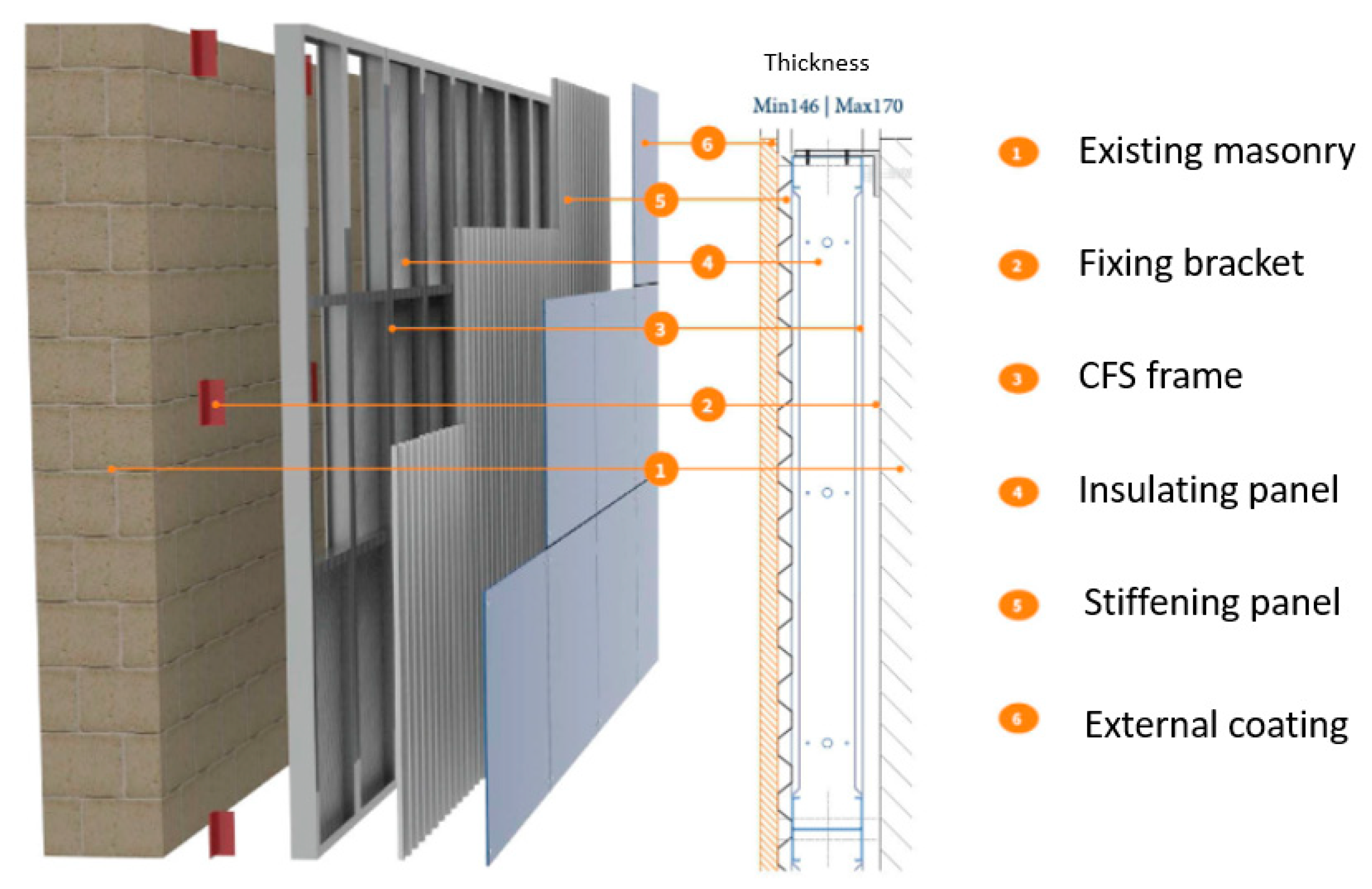
5.4. The DUO System Seismic Envelope
The DUO System seismic coating is a dry system for the seismic and energy retrofitting of existing buildings. It has numerous advantages, such as low transport costs, easy handling and quick assembly. It consists of three main parts:
A CFS (Cold Formed Steel) framed structure (
Figure 13), made up of mullions, having upper and lower guides, and transoms connected to each other by rivets.
OSB (Oriented Strand Board) panels, which absorb seismic actions, also offering an excellent thermal insulation. These seismic-tolerant systems are connected by screws to the CFS frame.
A final layer having the role of energy insulation system, which is inserted between the CFS frame and OSB panels. It can be made of ultra-thin and heat-reflecting layers composed of atomised aluminized polyethylene, sheep wool or wadding and polyurethane foams.
Figure 14 shows the assembly of components of the DUO System seismic envelope.
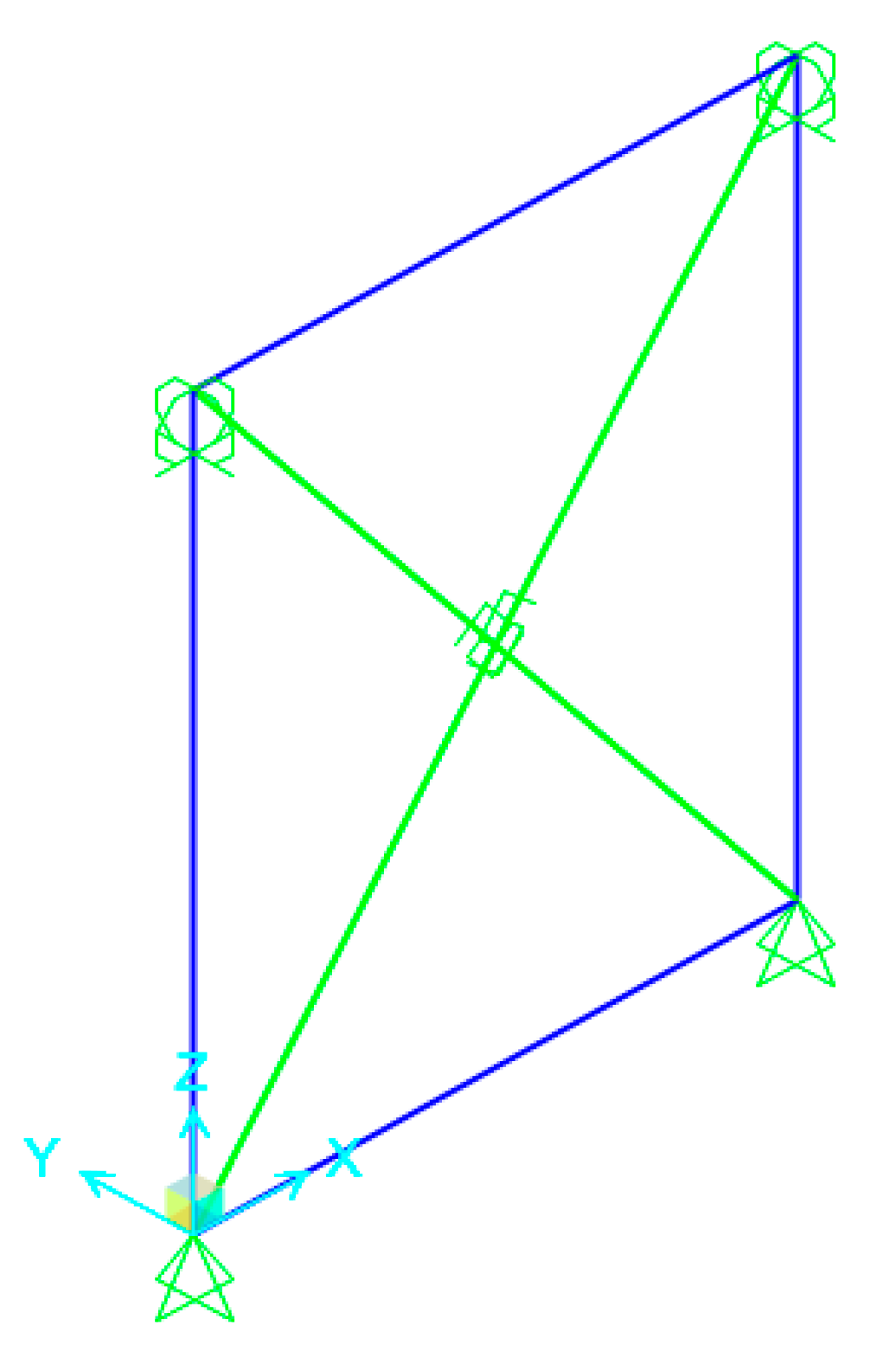
5.5. Numerical Analyses
The reinforcement system used herein consists in the application of the DUO System seismic envelope, composed of a CFS frame covered with 15 mm thick OSB panels. In the numerical model, the OSB panel is schematized by two diagonals, whose force-displacement behaviour has been calibrated in the SAP2000 software starting from the experimental test presented in [
42]. A body constraint guarantees the connection between the CFS frame and the equivalent frame structure made of piers and spandrels.
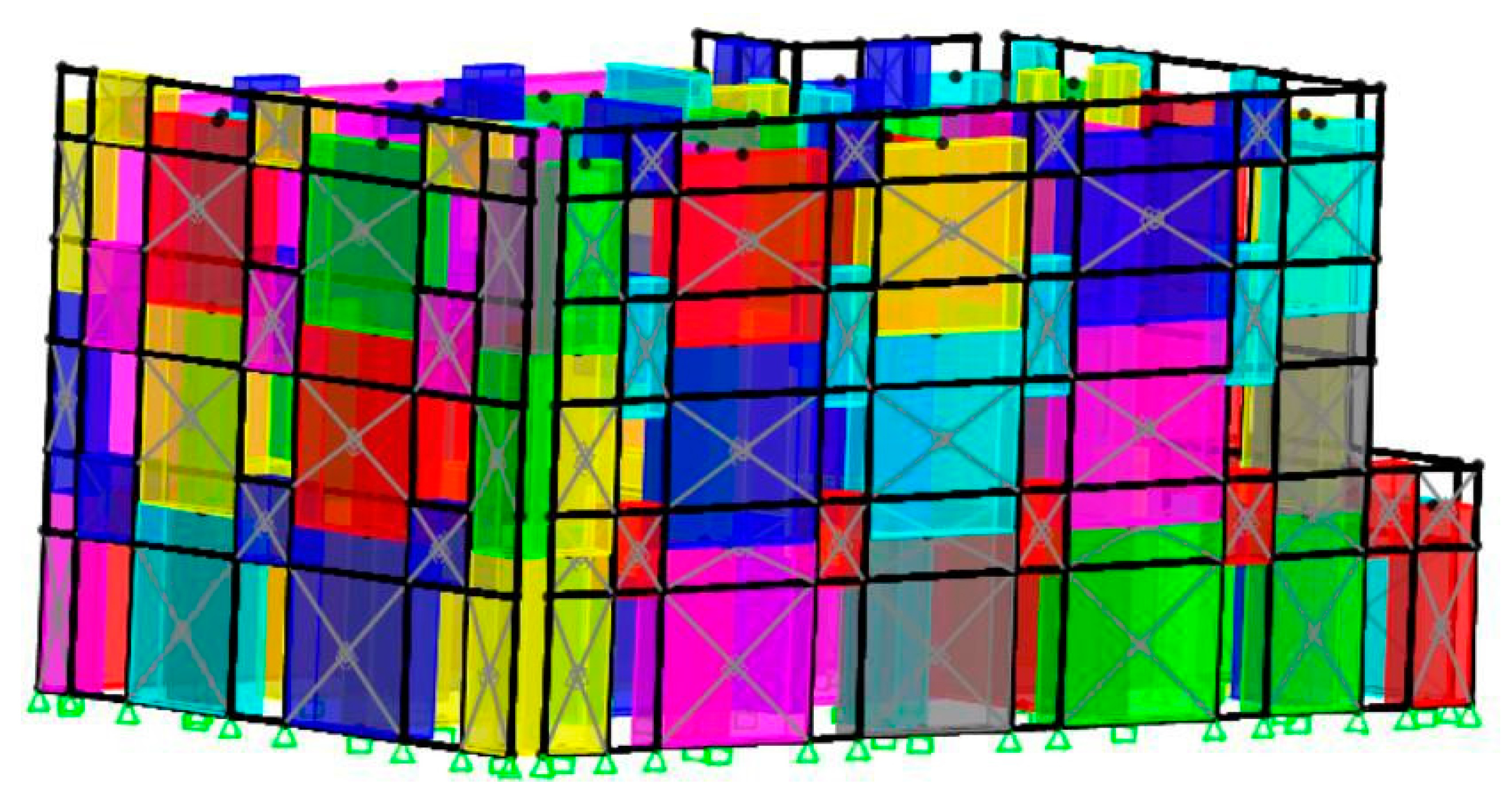
Figure 15 shows a single module representative of the CFS frame–OSB panel composite system. The DUO System seismic envelope is applied on all the perimeter walls, as reported in
Figure 16.
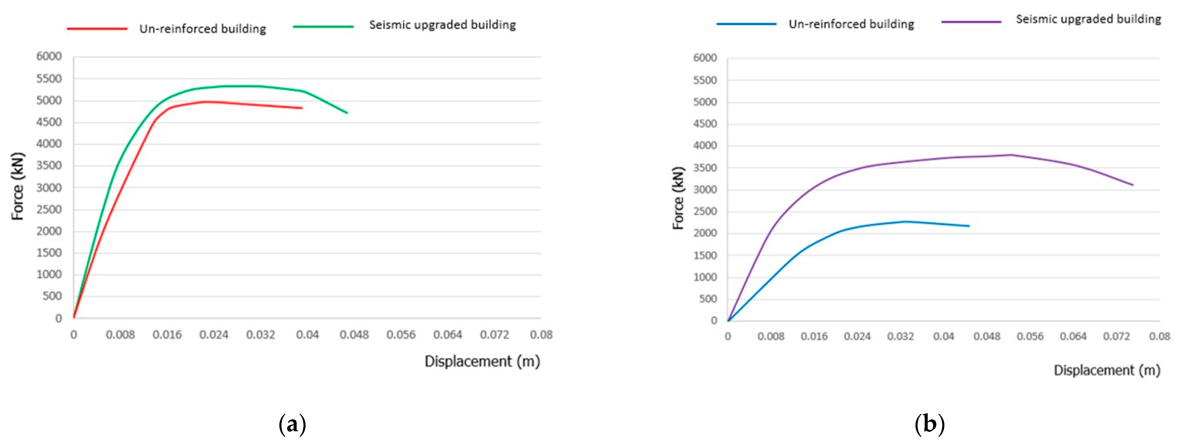
Figure 17a,b show the pushover curves of the upgraded building. The comparisons between the un-reinforced masonry building and the seismically upgraded one in terms of their force–displacement curves are depicted in
Figure 18a,b.
A further comparison between the performances of the un-retrofitted structure and the retrofitted one is reported in
Figure 19 in terms of final failure state in both analysis directions.
From the comparisons in
Figure 19, it is apparent that the insertion of the new seismic protection system reduces the number of plastic hinges in the bare building, so to be effective in reducing the earthquake damages of the masonry structure.
As it is seen from the curves of
Figure 18, the seismic envelope significantly improves the ductility, strength and stiffness of the existing building.
Ductility is evaluated according to the following formula:
where
dy is the elastic limit displacement and
du is the ultimate one. The greater
du is than
dy, the more the building is able to exhibit a behaviour in the plastic field, avoiding brittle crisis.
Stiffness is evaluated by considering the ratio between force and displacement at the elastic limit, as shown in the following equation:
The results of the comparison between the ante-operam (un-reinforced) building and the post-operam (upgraded) one in terms of ductility, strength and stiffness are depicted in
Table 3,
Table 4 and
Table 5, respectively, where it is worth of noticing that the building has smaller strength capacity in the y-direction. More in detail, in the x-direction, the post-operam building shows an increase of 64%, 7% and 25% in term of ductility, strength and stiffness, respectively, with respect to the ante-operam one. Instead, in the y-direction, the ductility, strength and stiffness of the post-operam building are greater than 41%, 66% and 107% of the ante-operam building ones, respectively.
6. Conclusions
In this paper, the seismic upgrading of a masonry building located in the municipality of Torre Annunziata, a city in the district of Naples (Italy), is proposed by applying mainly the innovative DUO system seismic envelope. The building has an irregular shape and is currently used for residential purposes. Over the years, this building underwent several transformations. Actually, it was developed on three floors, and it is unusable. The floors are made of vaults and wooden floors, the latter in some cases reinforced by steel profiles. First, the mechanical features of masonry were determined by on-site tests. Later on, the seismic behaviour of the building was assessed in the non-linear field through the SAP 2000 software. The detected seismic deficiencies allowed setting up and designing a series of seismic upgrading interventions, whose effectiveness was always evaluated by pushover curves in the SAP 2000 software environment. The proposed interventions were the insertion of steel tie-beams, the replacement of the existing deformable floors with rigid ones, the replacement of damaged masonry and the insertion of the DUO System seismic envelope on perimeter walls. The latter is an innovative, low-cost, sustainable and reversible envelope system having the aim to reach the energetic and seismic improvement of existing buildings.
The combined use of the above-mentioned seismic interventions with the application of the DUO System seismic envelope allowed the upgraded structure under examination to have a seismic behaviour in both analysis directions better than that of the un-reinforced one. In particular, in the x-direction, increases of 64%, 7% and 25% in terms of the ductility, strength and stiffness, respectively, are achieved, whereas, in the y-direction, the ductility, strength and stiffness increases are 41%, 66% and 107% larger than those of the ante-operam building, respectively.
As a conclusion, by obtaining the seismic upgrading of the building, the DUO System seismic envelope allows overcoming one seismic risk class according to the provisions of the Italian Superbonus Law, thus allowing the achievement of the 110% tax deduction of the costs of the proposed interventions.
Author Contributions
Conceptualization, A.F.; methodology, A.F.; software, G.V.; validation, A.F., formal analysis, G.V.; investigation, A.F. and G.V.; resources, A.F. and G.V.; data curation, A.F. and G.V.; writing—original draft preparation, G.V.; writing—review and editing, A.F.; visualization, A.F. and G.V.; supervision, A.F.; project administration, A.F. All authors have read and agreed to the published version of the manuscript.
Funding
This research received no external funding.
Institutional Review Board Statement
Not applicable.
Informed Consent Statement
Not applicable.
Data Availability Statement
Not applicable.
Acknowledgments
The authors would like to acknowledge the DUO System S.r.l. company, in the person of Alfonso Mastantuoni and his technical staff, for collaboration in the implementation of the DUO System seismic envelope.
Conflicts of Interest
The authors declare no conflict of interest.
References
- Lagomarsino, S. Seismic assessment of rocking masonry structures. Bull. Earthq. Eng. 2015, 13, 97–128. [Google Scholar] [CrossRef]
- Lourenço, P.B.; Mendes, N.; Ramos, L.F.; Oliveira, D.V. Analysis of masonry structures without box behavior. Int. J. Archit. Herit. 2011, 5, 369–382. [Google Scholar] [CrossRef]
- Sorrentino, L.; Cattari, S.; Da Porto, F.; Magenes, G.; Penna, A. Seismic behaviour of ordinary masonry buildings during the 2016 central Italy earthquakes. Bull. Earthq. Eng. 2019, 17, 5583–5607. [Google Scholar] [CrossRef] [Green Version]
- Clementi, F.; Gazzani, V.; Poiani, M.; Mezzapelle, P.A.; Lenci, S. Seismic assessment of a monumental building through nonlinear analyses of a 3D solid model. J. Earthq. Eng. 2018, 22, 35–61. [Google Scholar] [CrossRef]
- Fonti, R.; Borri, A.; Barthel, R.; Candela, M.; Formisano, A. Rubble masonry response under cyclic actions: Experimental tests and theoretical models. Int. J. Mason. Res. 2017, 2, 30–60. [Google Scholar] [CrossRef]
- Valente, M.; Milani, G. Effects of Geometrical Features on the Seismic Response of Historical Masonry Towers. J. Earthq. Eng. 2017, 22, 1–33. [Google Scholar] [CrossRef]
- Formisano, A.; Chieffo, N.; Milo, B.; Fabbrocino, F. The influence of local mechanisms on large scale seismic vulnerability estimation of masonry building aggregates. AIP Conf. Proc. 2016, 1790, 130010. [Google Scholar] [CrossRef]
- Formisano, A.; Vaiano, G.; Fabbrocino, F.; Milani, G. Seismic vulnerability of Italian masonry churches: The case of the Nativity of Blessed Virgin Mary in Stellata of Bondeno. J. Build. Eng. 2016, 20, 179–200. [Google Scholar] [CrossRef]
- Livesley, R.K. Limit analysis of structures formed from rigid blocks. Int. J. Numer. Methods Eng. 1978, 12, 1853–1871. [Google Scholar] [CrossRef]
- Calvi, G.M. Choices and Criteria for Seismic Strengthening. J. Earthq. Eng. 2013, 17, 769–802. [Google Scholar] [CrossRef]
- Thermou, G.E.; Pantazopoulou, S.J.; Elnashai, A.S. Design Methodology for Seismic Upgrading of Substandard Reinforced Concrete Structures. J. Earthq. Eng. 2007, 11, 582–606. [Google Scholar] [CrossRef]
- Caterino, N.; Iervolino, I.; Manfredi, G.; Cosenza, E. Multi-Criteria Decision Making for Seismic Retrofitting of RC Structures. J. Earthq. Eng. 2008, 12, 555–583. [Google Scholar] [CrossRef]
- da Porto, F.; Valluzzi, M.R.; Munari, M.; Modena, C.; Arêde, A.; Costa, A.A. Strengthening of stone and brick masonry buildings. In Strengthening and Retrofitting of Existing Structures; Springer: Berlin/Heidelberg, Germany, 2018; pp. 59–84. [Google Scholar]
- Babatunde, S.A. Review of strengthening techniques for masonry using fiber reinforced polymers. Compos. Struct. 2017, 161, 246–255. [Google Scholar] [CrossRef]
- Corradi, M.; Di Schino, A.; Borri, A.; Rufini, R. A review of the use of stainless steel for masonry repair and reinforcement. Constr. Build. Mater. 2018, 181, 335–346. [Google Scholar] [CrossRef]
- Formisano, A.; Vaiano, G.; Fabbrocino, F. Seismic and energetic interventions on a typical South Italy residential building: Cost analysis and tax detraction. Front. Built Environ. 2019, 5, 1–15. [Google Scholar] [CrossRef] [Green Version]
- Pierdicca, A.; Clementi, F.; Isidori, D.; Concettoni, E.; Cristalli, C.; Lenci, S. Numerical model upgrading of a historical masonry palace monitored with a wireless sensors network. Int. J. Mason. Res. 2016, 1, 74–99. [Google Scholar] [CrossRef]
- Quagliarini, E.; Maracchini, F.; Clementi, F. Uses and limits of the equivalent frame model on existing un-reinforced masonry buildings for assessing their seismic risk: A review. J. Build. Eng. 2017, 10, 166–182. [Google Scholar] [CrossRef]
- La Manna Ambrosino, G.; Brigante, D.; Mauro, A.; Formisano, A. Concept, prototyping and application of a tensioning system for FRP ties into masonry structures. Key Eng. Mater. 2017, 747, 298–304. [Google Scholar] [CrossRef]
- Milani, G.; Shehu, R.; Valente, M. Possibilities and limitations of innovative retro-fitting for masonry churches: Advanced computations on three case studies. Constr. Build. Mater. 2017, 147, 239–263. [Google Scholar] [CrossRef]
- Ramaglia, G.; Lignola, G.P.; Fabbrocino, F.; Prota, A. Numerical investigation of masonry strengthened with composites. Polymers 2018, 10, 334. [Google Scholar] [CrossRef] [Green Version]
- Micelli, F.; Cascardi, A.; Marsano, M. Seismic strengthening of a theatre masonry building by using active FRP wires. In Brick and Block Masonry, Proceedings of the 16th International Brick and Block Masonry Conference, Padua, Italy, 26–30 June 2016; CRC Press: Padova, Italy, 2016; pp. 753–761. [Google Scholar]
- Longo, F.; Lassandro, P.; Moshiri, A.; Phatak, T.; Aiello, M.A.; Krakowiak, K.J. Lightweight geopolymer-based mortars for the structural and energy retrofit of buildings. Energy Build. 2020, 225, 110352. [Google Scholar] [CrossRef]
- Longo, F.; Cascardi, A.; Lassandro, P.; Aiello, M.A. Energy and seismic drawbacks of masonry: A unified retrofitting solution. J. Build. Rehabil. 2021, 6, 1–24. [Google Scholar] [CrossRef]
- Caprino, A.; Lorenzoni, F.; Canieletto, L.; Feletto, L.; De Carli, M.; da Porto, F. Integrated Seismic and Energy Retrofit Interventions on a URM Masonry Building: The Case Study of the Former Courthouse in Fabriano. Sustainability 2021, 13, 9592. [Google Scholar] [CrossRef]
- Mastroberti, M.; Bournas, D.A.; Vona, M.; Manganelli, B. Combined Seismic Plus Enery Retrofitting for the Existing RC Buildings: Economic Feasibility; European Association for Earthquake Engineering: Tokyo, Japan, 2018; 16ECEE. [Google Scholar]
- Law 19th May 2020, n.34. Italian Relaunch Decree Related to the Application of the Superbonus to Residential Buildings; General series n. 180; Official Gazette of the Italian Republic: Rome, Italy, 2020. (In Italian)
- ASTM International. ASTM C1196-20. Standard Test Method for In Situ Compressive Stress within Solid Unit Masonry Estimated Using Flat Jack Measurements; ASTM International: West Conshohocken, PA, USA, 2020. [Google Scholar]
- ASTM International. ASTM C1197-20e1. Standard Test Method for In Situ Measurement of Masonry Deformability Properties Using the Flat Jack Method; ASTM International: West Conshohocken, PA, USA, 2020. [Google Scholar]
- NTC. Ministerial Decree, D.M. 20.02.2018 Updating of Technical Standards for Construction; NTC: Quezon City, Philippines, 2018. [Google Scholar]
- Ministry of Infrastructure and Transport. Instructions for the Application of the New Technical Code for Constructions, n. 35; Ministry of Infrastructure and Transport: Rome, Italy, 2019.
- Roca, P.; Molins, C.; Marí, A.R. Strength capacity of masonry wall structures by the equivalent frame method. J. Struct. Eng. 2005, 131, 1601–1610. [Google Scholar] [CrossRef]
- Belmouden, Y.; Lestuzzi, P. An equivalent frame model for seismic analysis of masonry and reinforced concrete buildings. Constr. Build. Mater. 2009, 23, 40–53. [Google Scholar] [CrossRef]
- Berti, M.; Salvatori, L.; Orlando, M.; Spinelli, P. Un-reinforced masonry walls with irregular opening layouts: Reliability of equivalent-frame modelling for seismic vulnerability assessment. Bull. Earthq. Eng. 2017, 15, 1213–1239. [Google Scholar] [CrossRef]
- Lagomarsino, S.; Penna, A.; Galasco, A.; Cattari, S. TREMURI program: An equivalent frame model for the nonlinear seismic analysis of masonry buildings. Eng. Struct. 2013, 56, 1787–1799. [Google Scholar] [CrossRef]
- Addessi, D.; Mastrandrea, A.; Sacco, E. An equilibrated macro-element for nonlinear analysis of masonry structures. Eng. Struct. 2013, 70, 82–93. [Google Scholar] [CrossRef]
- Penna, A.; Lagomarsino, S.; Galasco, A. A nonlinear macroelement model for the seismic analysis of masonry buildings. Earthq. Eng. Struct. Dyn. 2014, 43, 159–179. [Google Scholar] [CrossRef]
- Penna, A.; Senaldi, I.E.; Galasco, A.; Magenes, G. Numerical simulation of shaking table tests on full-scale stone masonry buildings. Int. J. Architect. Herit. 2016, 10, 146–163. [Google Scholar] [CrossRef]
- Mandirola, M.; Galasco, A.; Penna, A.; Magenes, G. Nonlinear macroelement modelling of experimental tests on masonry buildings with rigid diaphragms. In Proceedings of the 16th International Brick and Block Masonry Conference, Padova, Italy, 2–5 June 2013. [Google Scholar]
- Dolce, M. Schematization and modeling by actions in the plan of the walls. In Course on Consolidation of Masonry Buildings in Seismic Zone; Order of Engineers: Potenza, Italy, 1989. (In Italian) [Google Scholar]
- Pasticier, L.; Amadio, C.; Fragiacomo, M. Non-linear seismic analysis and vulnerability evaluation of a masonry building by means of the SAP2000 V.10. Earthq. Eng. Struct. Dyn. 2007, 37, 467–485. [Google Scholar] [CrossRef]
- Liu, X.; Wu, H.; Sang, L.; Sui, L.; Xu, C. Estimation of Inelastic Interstorey Drift for OSB/Gypsum Sheathed Cold-Formed Steel Structures under Collapse Level Earthquakes. Adv. Mater. Sci. 2019, 2019, 2896938. [Google Scholar] [CrossRef] [Green Version]
Figure 1.
Case study photographic survey: (a) street view; (b) interior of the ground floor; (c) interior of the first floor; (d) interior of the second floor.
Figure 1.
Case study photographic survey: (a) street view; (b) interior of the ground floor; (c) interior of the first floor; (d) interior of the second floor.
Figure 2.
Case study plan layout: (a) ground floor; (b) first floor; (c) second floor.
Figure 2.
Case study plan layout: (a) ground floor; (b) first floor; (c) second floor.
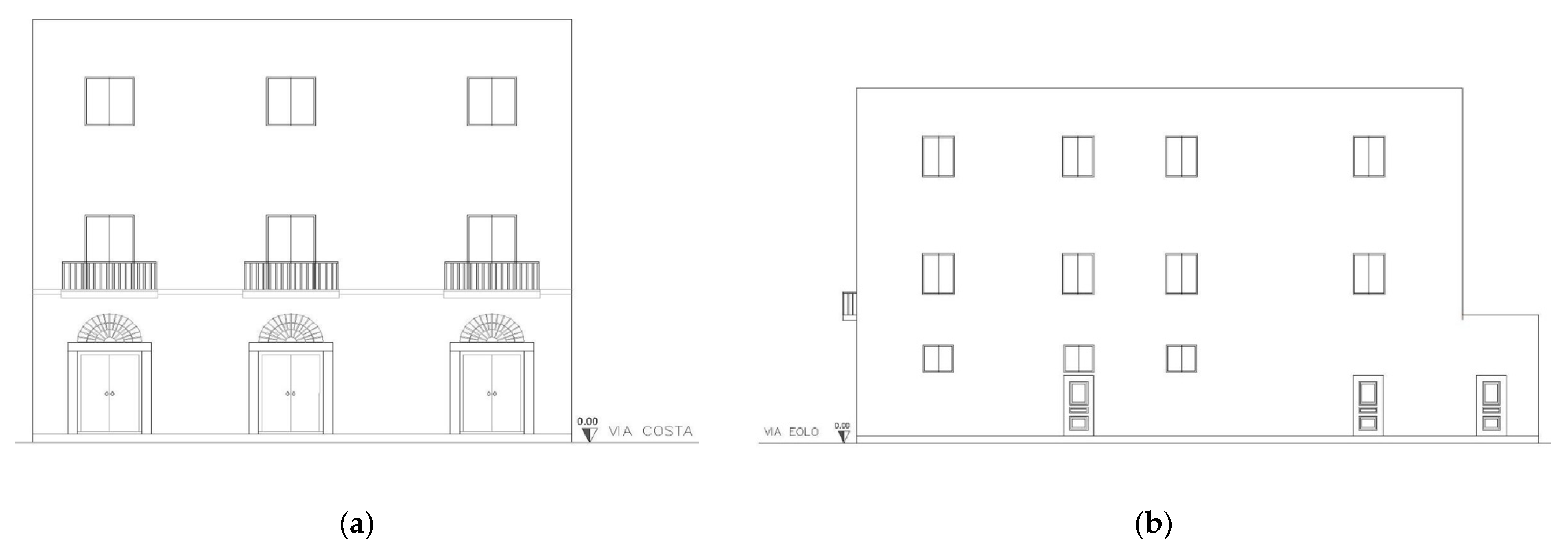
Figure 3.
External views: (a) south side; (b) east side.
Figure 3.
External views: (a) south side; (b) east side.
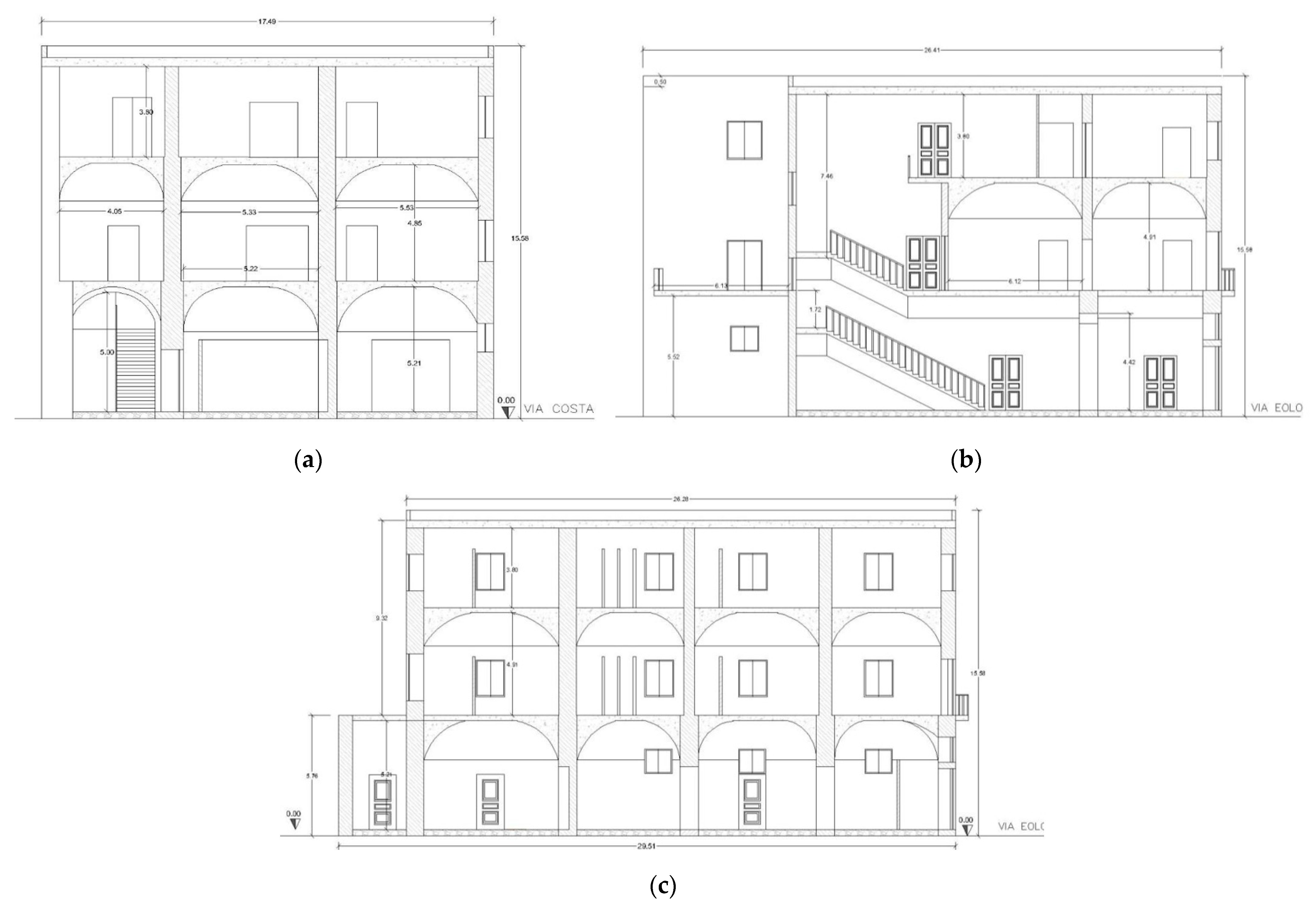
Figure 4.
Building sections (positions in
Figure 2): (
a) x-x’; (
b) y-y’; (
c) z-z’.
Figure 4.
Building sections (positions in
Figure 2): (
a) x-x’; (
b) y-y’; (
c) z-z’.
Figure 5.
Location of on-site tests: (a) ground floor; (b) second floor.
Figure 5.
Location of on-site tests: (a) ground floor; (b) second floor.
Figure 6.
The equivalent frame model approach.
Figure 6.
The equivalent frame model approach.
Figure 7.
The building’s 3D model developed by the SAP2000 analysis software.
Figure 7.
The building’s 3D model developed by the SAP2000 analysis software.
Figure 8.
Behaviour of plastic hinges for piers (a) and spandrels (b).
Figure 8.
Behaviour of plastic hinges for piers (a) and spandrels (b).
Figure 9.
Pushover curves of the un-retrofitted structure: (a) x-direction; (b) y-direction.
Figure 9.
Pushover curves of the un-retrofitted structure: (a) x-direction; (b) y-direction.
Figure 10.
External steel tie-beams applied on (a) perimetral walls, (b) internal walls and (c) aggregate walls.
Figure 10.
External steel tie-beams applied on (a) perimetral walls, (b) internal walls and (c) aggregate walls.
Figure 11.
Mixed steel–concrete floor used to replace the wooden one.
Figure 11.
Mixed steel–concrete floor used to replace the wooden one.
Figure 12.
The “scuci and cuci” technique.
Figure 12.
The “scuci and cuci” technique.
Figure 13.
Cross-section of the basic CFS profile used in the DUO system seismic envelope.
Figure 13.
Cross-section of the basic CFS profile used in the DUO system seismic envelope.
Figure 14.
The DUO System seismic envelope.
Figure 14.
The DUO System seismic envelope.
Figure 15.
Single module representative of the CSF frame-OSB panel system modelled in the SAP2000 software.
Figure 15.
Single module representative of the CSF frame-OSB panel system modelled in the SAP2000 software.
Figure 16.
SAP 2000 3D model of the building externally reinforced with the DUO System seismic envelope.
Figure 16.
SAP 2000 3D model of the building externally reinforced with the DUO System seismic envelope.
Figure 17.
Pushover curves of the seismic upgraded building: (a) x-direction; (b) y-direction.
Figure 17.
Pushover curves of the seismic upgraded building: (a) x-direction; (b) y-direction.
Figure 18.
Comparisons between the un-reinforced building and the seismic upgraded one in term of force–displacement curve: (a) x-direction; (b) y-direction.
Figure 18.
Comparisons between the un-reinforced building and the seismic upgraded one in term of force–displacement curve: (a) x-direction; (b) y-direction.
Figure 19.
Damage distribution of the un-reinforced building in x (a) and y (b) directions and of the reinforced building in x (c) and y (d) directions.
Figure 19.
Damage distribution of the un-reinforced building in x (a) and y (b) directions and of the reinforced building in x (c) and y (d) directions.
Table 1.
On-site test data.
Table 1.
On-site test data.
| Jack surface | 715.34 cm2 |
| Jack thickness | 4.0 mm |
| Diameter | 34.70 cm |
| Km | 0.90 |
| Cut surface | 796 cm2 |
| Ka | 0.915 |
Table 2.
On-site test results in term of compressive strength and elastic modulus values.
Table 2.
On-site test results in term of compressive strength and elastic modulus values.
| On-Site Test | Compression Strength [MPa] | Elastic Modulus
[MPa] |
|---|
| MSD1 | 0.82 | 852.66 |
| MSD2 | 0.99 | 840.58 |
| MSD3 | 0.82 | 920.99 |
Table 3.
Comparison between the un-reinforced building and the seismically upgraded one in terms of ductility.
Table 3.
Comparison between the un-reinforced building and the seismically upgraded one in terms of ductility.
| | dy,X
[cm] | du,X
[cm] | dy,Y
[cm] | du,Y
[cm] | μ
X-Direction | μ
Y-Direction |
|---|
| Un-reinforced building | 0.54 | 2.19 | 0.74 | 3.36 | 3.05 | 3.54 |
Upgraded
building | 0.51 | 3.06 | 0.88 | 5.29 | 5.00 | 5.01 |
Table 4.
Comparison between the un-reinforced building and the seismically upgraded one in terms of strength.
Table 4.
Comparison between the un-reinforced building and the seismically upgraded one in terms of strength.
| | Fmax,X
[kN] | Fmax,Y
[kN] |
|---|
| Un-reinforced building | 4969 | 2282 |
| Upgraded building | 5325 | 3797 |
Table 5.
Comparison between the un-reinforced building and the seismically upgraded one in terms of stiffness.
Table 5.
Comparison between the un-reinforced building and the seismically upgraded one in terms of stiffness.
| | dy,X
[cm] | Fy,X
[kN] | dy,Y
[cm] | Fy,Y
[kN] | Kx
[kN/cm] | Ky
[kN/cm] |
|---|
| Un-reinforced building | 0.54 | 2129 | 0.74 | 904 | 3942 | 1222 |
Upgraded
building | 0.51 | 2522 | 0.88 | 2228 | 4945 | 2532 |
| Publisher’s Note: MDPI stays neutral with regard to jurisdictional claims in published maps and institutional affiliations. |
© 2021 by the authors. Licensee MDPI, Basel, Switzerland. This article is an open access article distributed under the terms and conditions of the Creative Commons Attribution (CC BY) license (https://creativecommons.org/licenses/by/4.0/).


