Article

A New Method of Gold Foil Damage Detection in Stone Carving Relics Based on Multi-Temporal 3D LiDAR Point Clouds

Beijing University of Civil Engineering and Architecture, NO. 1, Zhanlanguan Road, Xicheng District, Beijing 100044, China
*
Author to whom correspondence should be addressed.
ISPRS Int. J. Geo-Inf. 2016, 5(5), 60; https://0-doi-org.brum.beds.ac.uk/10.3390/ijgi5050060
Submission received: 11 January 2016 / Revised: 20 April 2016 / Accepted: 3 May 2016 / Published: 9 May 2016
(This article belongs to the Special Issue Bridging the Gap between Geospatial Theory and Technology)

Abstract

:
The timely detection of gold foil damage in gold-overlaid stone carvings and the associated maintenance of these relics pose several challenges to both the research and heritage protection communities internationally. This paper presents a new method for detecting gold foil damage by making use of multi-temporal 3D LiDAR point clouds. By analyzing the errors involved in the detection process, a formula is developed for calculation of the damage detection threshold. An improved division method for the linear octree that only allocates memory to the non-blank nodes, is proposed, which improves storage and retrieval efficiency for the point clouds. Meanwhile, the damage-occurrence regions are determined according to Hausdorff distances. Using a triangular mesh, damaged regions can be identified and measured in order to determine the relic’s total damaged area. Results demonstrate that this method can effectively detect gold foil damage in stone carvings. The identified surface area of damaged regions can provide the information needed for subsequent restoration and protection of relics of this type.

1. Introduction

Stone carvings embody the history of ancient people and are an important part of cultural relics, especially large stone Buddha statues and stone inscriptions on precipices [1]. In some stone carvings, gold is overlaid on the surface to highlight its status and luxury. For example, some of the large gold-overlaid stone relics in China include the Tongnan Buddha and the Thousand-Hand Bodhisattva Statue in Chongqing. They are decorated with gold foil to protect the base against weathering (fading, flaking, chalking, contamination, etc.) and increase the sense of prestige and mystique while catering to people’s admiration of gold.
However, the third survey of cultural relics in China at the end of 2011 showed that nearly one-fourth of these relics, especially stone carvings, are in poor condition. For example, an on-site survey found that the Thousand-Hand Bodhisattva Statue in Chongqing is seriously damaged and that gold foil had fallen off due to weathering and other factors. This has resulted in two kinds of damage: (1) surface integrity changes (such as fall-off, curling, and delamination cracking) and (2) surface morphology changes (such as bending and bulging, as shown in Figure 1). The maintenance of gold foil is difficult, complicated, and requires a large amount of resources. For example, maintenance of the Thousand-Hand Bodhisattva Statue in Chongqing required 20 steps, 6 years, and millions of Chinese Yuan Renminbi (CNY). Therefore, the timely detection and maintenance of gold foil damage in gold-overlaid stone carvings would not only greatly reduce repair costs, but also avoid further damage of the internal rock mass.
Protection of stone carvings started late in China. In the beginning, research on damage investigation was primarily carried out in an effort to record and summarize damage types, distributions, causes, severities, etc. However, this type of investigation does not study the subtle changes of the damage. In some instances, damage could be non-superficial, and further damage could easily be caused by touching the surface. Furthermore, such methods also require a large labor commitment [1]. Hence, some scholars have suggested adopting a method of close-range photogrammetry to detect stone relic damage [2,3,4]. The plane and elevation graphs prepared using close-range photogrammetry can be accurate to millimeters. However, climatic conditions, viewing angle, and lighting have a significant impact on close-range photogrammetry. Furthermore, image interpretation is complicated, and, even though some damage can be detected, multi-temporal image data are not overlaid to reflect damage development conditions. As a result, this method is not completely effective.
The emergence of 3D laser scanning technology has provided a new way to detect damage in stone relics. The most important advantage of this technology is the direct acquisition of dense 3D point cloud data, which can reflect details on the surface of detected objects [5,6]. In recent years, several researchers have successfully taken advantage of 3D laser scanning technology in monitoring and studying structures, landslides, and surface subsidence [7,8,9]. Girardeau-Montaut et al. proposed contrasting 3D point clouds in different temporal points to detect changes in stone carvings and proposed a false change problem in the detection process [10]. Wawrzyniec et al. regularly observed cliff conditions using 3D laser scanning technology and proposed that changes could be accurately detected to within sub-centimeter accuracy through point cloud contrast [11]. Zhao et al. adopted point cloud data to detect changes in building walls. By directly comparing point-to-point distances using the Hausdorff distance calculation method, the range of change was determined according to a set threshold, adding to the existing false change method [12].
Stone relics are invaluable resources of great historical, artistic, and scientific value. Therefore, relic surveys and information retention is not only a basic but also a technical task for protection. Due to the irregular geometric shape and complex structure of stone carvings, 3D laser scanning technology is usually adopted. This provides for non-destructive evaluation, high accuracy, speed, and other prominent properties to acquire fine and comprehensive data. Up to now, scholars have applied 3D laser scanning technology for information retention [13], stability estimation [14], virtual restoration [15], and even archaeological survey [16]. However, little effort has been made in using 3D laser scanning technology for detecting changes in gold foil.
This study focuses on the variational area of gold foil damage in stone carving relics and takes advantage of 3D laser scanning technology to identify and accurately measure the damaged area through contrast of collected multi-temporal point clouds. Such data can provide support for the subsequent restoration and protection of cultural relics. This paper is organized as follows. After the introduction, which has here provided a review of existing methods and the corresponding problems, Section 2 presents the proposed method used to detect changes in gold foil. This is followed by details of the parameter determination. Section 3 describes the experimental area and data processing steps. Section 4 focuses primarily on analyzing the results obtained using the proposed method, including retrieval efficiency, damaged area determination, and area calculation. Finally, Section 5 concludes the paper with directions for further study.

2. Study Method

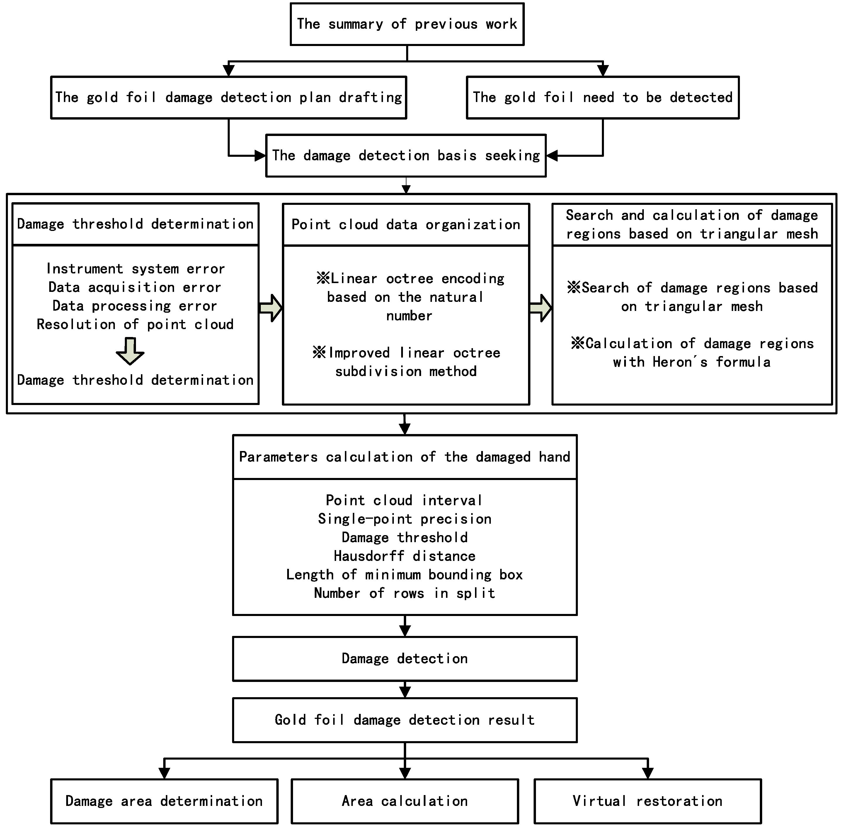
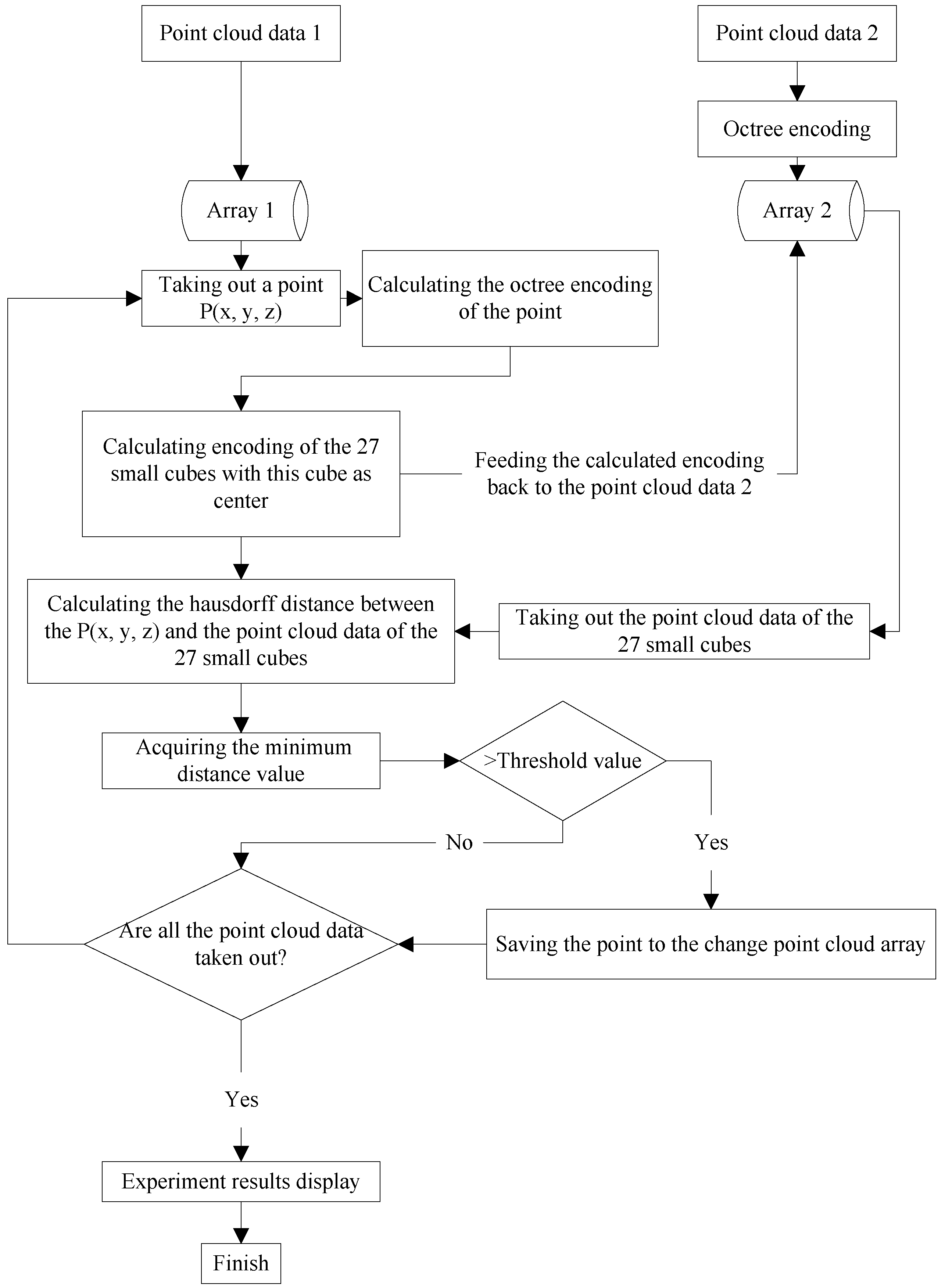
2.1. The Proposed Method

As restoration work is difficult, complex, time-consuming, and costly, it is highly important to find an effective restoration technique for future relic protection. With this as a starting point, a method for using a linear octree to organize point clouds is proposed in this paper. On the basis of this linear octree, an encoding scheme is modified which allows for a conversion of the octal number of the octants in the tree to a natural number, thereby improving the retrieval efficiency. A method for splitting with higher memory utilization is simultaneously established, which could significantly reduce costs. Finally, an algorithm is developed for searching the affected area using the triangular mesh model, in which Heron’s formula is used to calculate the surface area of the region of interest. The paper is organized as shown in Figure 2.

2.2. Gold Foil Damage Detection Based on an Improved Linear Octree

2.2.1. Damage Threshold Determination

(1) Error Analysis 

There are three types of errors that can occur in the collection and processing of point cloud data. The first type is instrument system error, which is mainly constrained by range errors, angle errors [17], point cloud data resolution, and even properties of the laser beam itself. The instrument error in a 3D laser scanner is normally given by the manufacturer but still must be calibrated to reduce inaccuracies. The second type of error is generated during the point cloud data collection process, including errors caused by the external environment (e.g., barometric pressure, temperature, and humidity). This includes errors caused by surface reflection of the target object (e.g., tilt level, texture, color, roughness, and marginal effects) and errors caused by scanner orientation. Among these, the precision of the scanner orientation directly affects the precision of the detection results [12]. The third type of error is caused by coordinate registration. During the data collection process, a single station may not be able to accomplish the collection of all object data. Therefore, several stations are required for data collection. The connection between any two stations depends on the common points scanned at both locations, in order to acquire conversion coefficients. The precision and distribution of the common points can directly affect the precision of the point cloud registration [12].

(2) Damage Threshold Determination 

Through error analysis, we can determine the threshold for the sum of multiple errors, which is used to determine whether damage is occurring or not. Furthermore, the resolution of point cloud data, which can also be called the scanning interval, needs to be considered as well. Therefore, the damage threshold can be determined using the following formula:
δ = α + β + γ + η
where δ is the damage threshold, α is the instrument system error, β is the point cloud data collection error, γ is the coordinate registration error, and η is the resolution of the point cloud data.

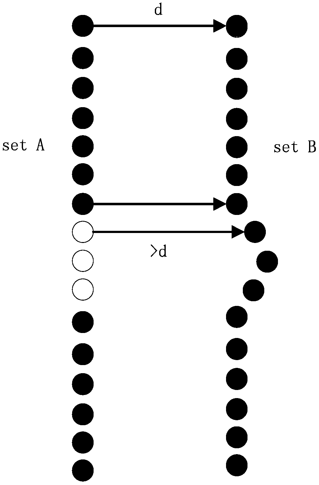
2.2.2. Partial Hausdorff Distance

In the field of computer vision, Hausdorff distance is often used for template image matching [18]. We introduced it into 3D space to determine the degree of similarity between multi-temporal point clouds in this paper and to further determine variational regions (i.e., gold foil damage regions).
A partial Hausdorff distance is defined as follows: If the set Q contains n points, the partial Hausdorff distance of the Kth (1 ≤ Kn) point is the Kth value in the Q collection after sorting. The formula is as follows:
h K ( Q , P ) = K q Q t h min p P q i p i
where K q Q t h represents the Kth value in the distance value collection after sorting from set Q to set P. The damaged region can be determined using the partial Hausdorff distance definition and the acquired damage threshold. Its geometric interpretation is shown in Figure 3. If the threshold of the given points is d, when the calculated partial Hausdorff distance is greater than d, the point can be regarded as a variational point as shown in Figure 4.
However, due to the scanning angle, occlusion, leakage, and other problems that occur during the detection process, the point cloud data, which belong to the same set, obtained from different scans may not be exactly the same. As a result, using the Hausdorff distance algorithm to detect point cloud data collected in different phases may result in data representing false changes. Therefore, supposing that the reference point cloud is non-damaged information, the changing point cloud data are the data that needs to be detected. It is essential to find and eliminate falsely changed areas by using the method of exchanging reference point cloud data and changing point cloud data. This is done in order to compare the point-to-point distances using the Hausdorff distance calculation method repeatedly.

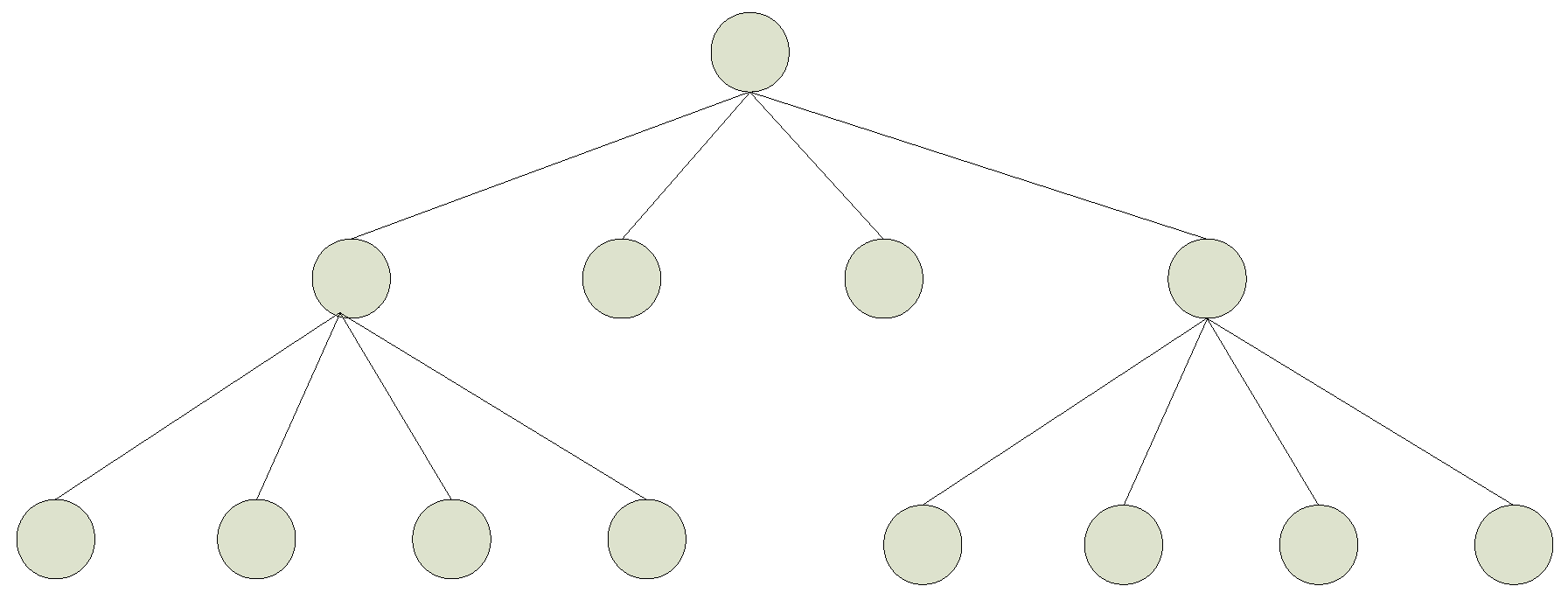
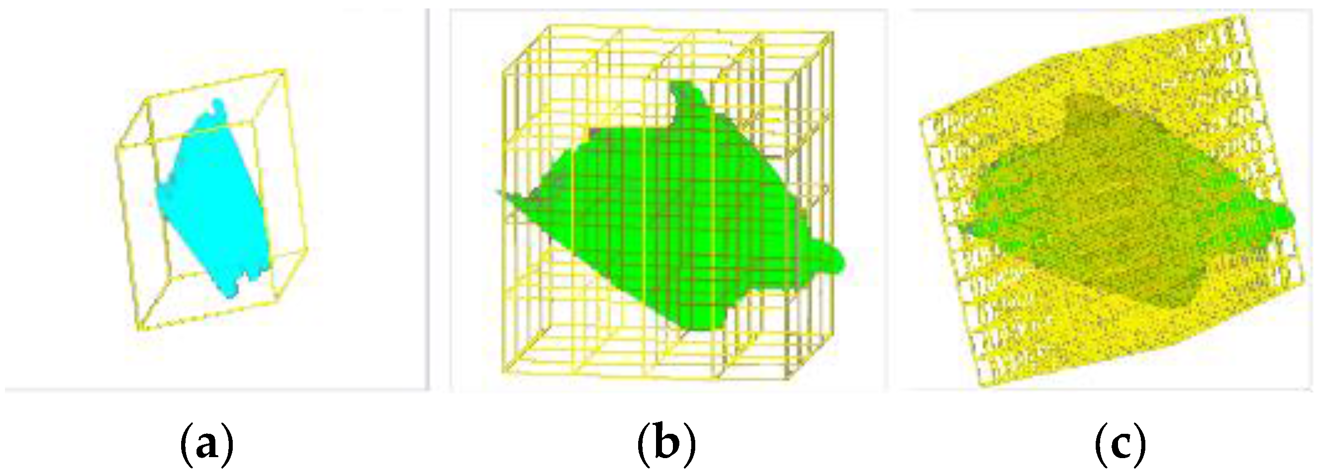
2.2.3. Point Cloud Data Organization Based on an Improved Linear Octree

(1) Linear octree subspace based on the natural number 

The conventional method of point cloud data organization is a hybrid structure of the KD tree and the octree. The KD tree, which originates from the binary tree, is a data structure for k dimensional space. In this way, each non-leaf node is divided into two subspaces by a hyperplane until all of the subspaces are divided into two parts (as seen in Figure 5).
Furthermore, compared to the quadtree structure, the KD tree has an obvious advantage in balance and flexibility acquired during spatial subdivision. As shown in Figure 6, the KD tree subdivision is the most flexible, with the fewest subdivision layers.
Even so, KD tree still has some disadvantages. Firstly, the structure is very sensitive to the insertion order of the data points. Although the adaptive KD tree changes the unbalanced state of the KD tree, the tree is completely static. And any update operation (e.g., insertion, deletion) would destroy the balance. Therefore, it is not suitable for frequently updates [19].
The octree, which is an extension of the quadtree structure (seen in Figure 7) and is typically used to describe three-dimensional space, is widely used in many domains, such as 3D modeling, voxel data compression, progressive transmission, and rendering applications. As each node contains eight sub-nodes, and every node represents a small cube in three-dimensional space, the sum of the eight small cubic volumes equals the volume of the parent node (as illustrated in Figure 8).
Furthermore, the linear octree encodes the leaf nodes with an octal number. Even though most programming languages support octal, it still requires appropriate memory units for storing nodes in the octal code of the point cloud data. This establishes a corresponding relationship between the octal node and the array subscript, which will greatly reduce the construction efficiency of the index. However, converting the octal number to decimal number and regarding the decimal number as the array subscript can completely bypass this inconvenience. Compared to octal number, decimal number is of great significance. For example, decimal number is in line with people’s habits, and it can be easily implemented in computer language, which will be fully reflected in the optimization algorithm [20]. In addition, point cloud data are large and finely expressed, and they have no topological relationship among 3D spatial points. For these reasons, we use a linear octree to organize data for calculating Hausdorff distances between two different temporal point cloud locations [21]. Not only is this convenient for searching adjacent points, it can greatly improve the operational efficiency of the Hausdorff distance.

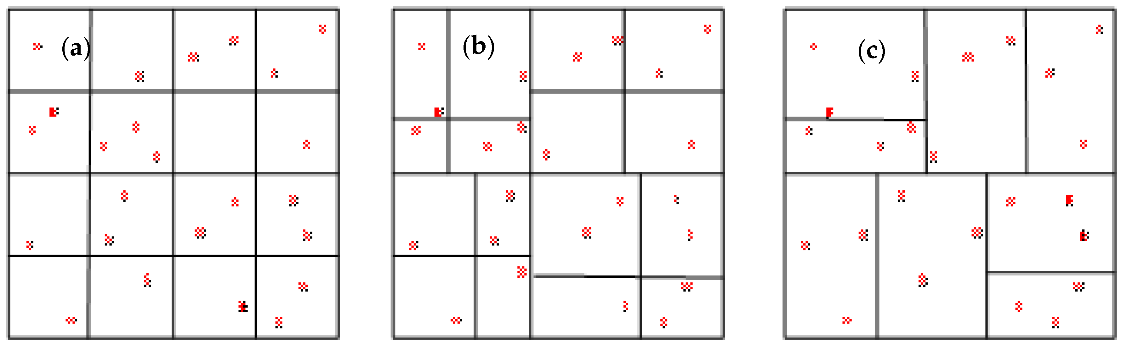
(2) An improved linear octree subdivision method 

Due to the benefits of a simple structure, concise code, and lower memory usage, linear octrees are widely used in point cloud organization [22,23,24,25,26]. However, given that point cloud data obtained by 3D laser scanning may originate from object surfaces, these data mainly reflect the shape of a thin shell, which may result in many empty nodes in the octal structure (see Figure 6). Though these blank nodes contain no data, they are still allocated memory space at the time of initial memory allocation. This results in a significant waste of memory and eventually leads to more serious circumstances, such as insufficient memory after the section is divided into a certain degree, and the division is unable to continue.
Therefore, an improved division method for the linear octree, one that only allocates memory to the non-blank nodes, is proposed. It requires a determination of whether the node is empty before memory is allocated. If the node is empty, no memory is allocated, which significantly reduces memory requirements.
The specific operating procedure is as follows:
(1)
Compute the bounding box for the point cloud. This is the root of the linear octree. Suppose that L is the length of the bounding box, L can be determined by the following formula:
L = Max(Xmax − Xmin, Ymax − Ymin, Zmax − Zmin)
Then, select the point with the smallest coordinates as the starting point of the bounding box. The bounding box can then be expressed as (Xmin, Ymin, Zmin, L).
(2)
Calculate voxel length. A voxel, whose length is determined by splitting, is the smallest cube after segmentation. If the splitting number equals n, the voxel length can be calculated by the following formula:
Pix=L/2n
(3)
Calculate decimal encoding for each point as their ID cards.
(4)
Count the number of decimal encoding values to acquire the nodes that are not empty by taking advantage of the map template for the STL (Standard Template Library) in C++.
(5)
Allocate memory for each node based on the number of nodes that exist.
(6)
Store the point clouds in the corresponding array, according to the point cloud IDs.

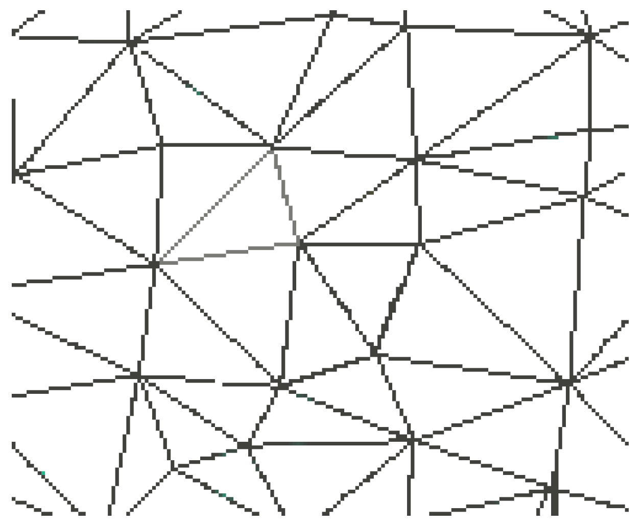
2.2.4. Search and Calculation of Damaged Regions Based on a Triangular Mesh

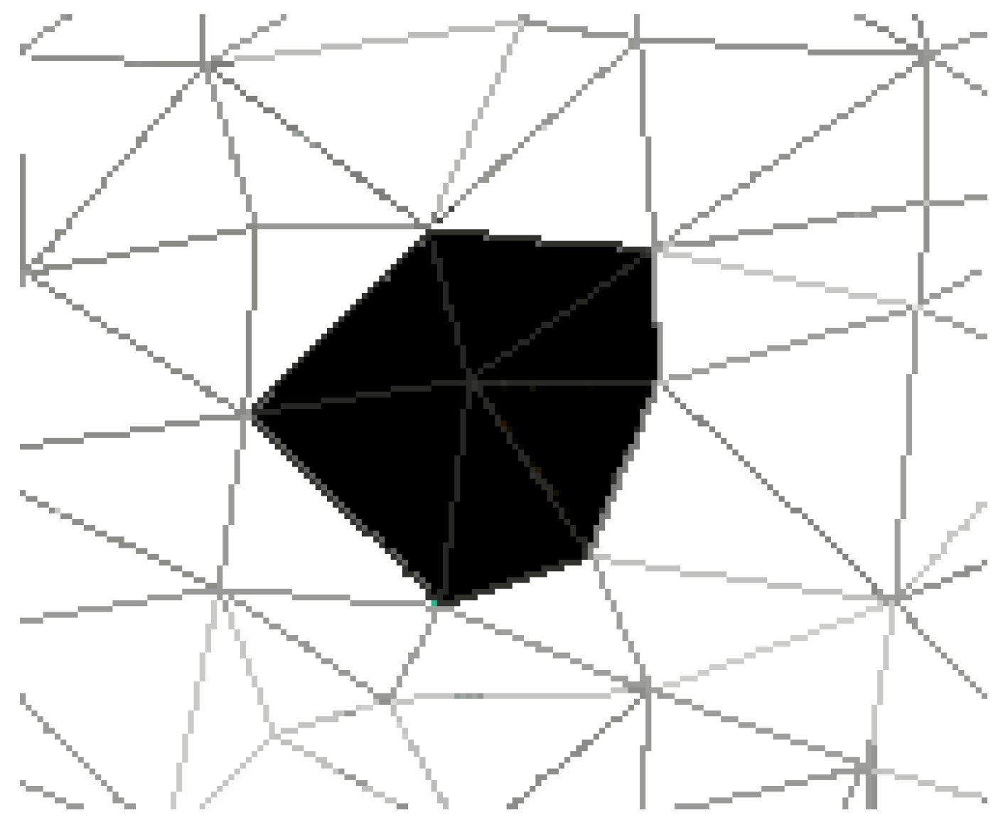
(1) Search of damaged regions based on a triangular mesh 

Using the Hausdorff distance calculation, points exceeding the identified threshold are regarded as points in the damaged region. However, point cloud data are not convenient for calculation of the damaged surface area. Therefore, this paper establishes a triangular mesh model based on point cloud data [27]. This model is an approximate representation of the surface of the object and the collection of triangular patches with detected points representing the vertex, as shown in Figure 9.
To some extent, the position change of one point cloud can reflect the surface-position change of the partial small neighbor area with a specific point as the vertex. Therefore, the collection of triangular patches using this point as a vertex can be established to represent the damaged area as shown in Figure 10. According to the detected point cloud in the damaged area, we can search for a collection of triangular patches with these points as vertexes, representing the damaged area.

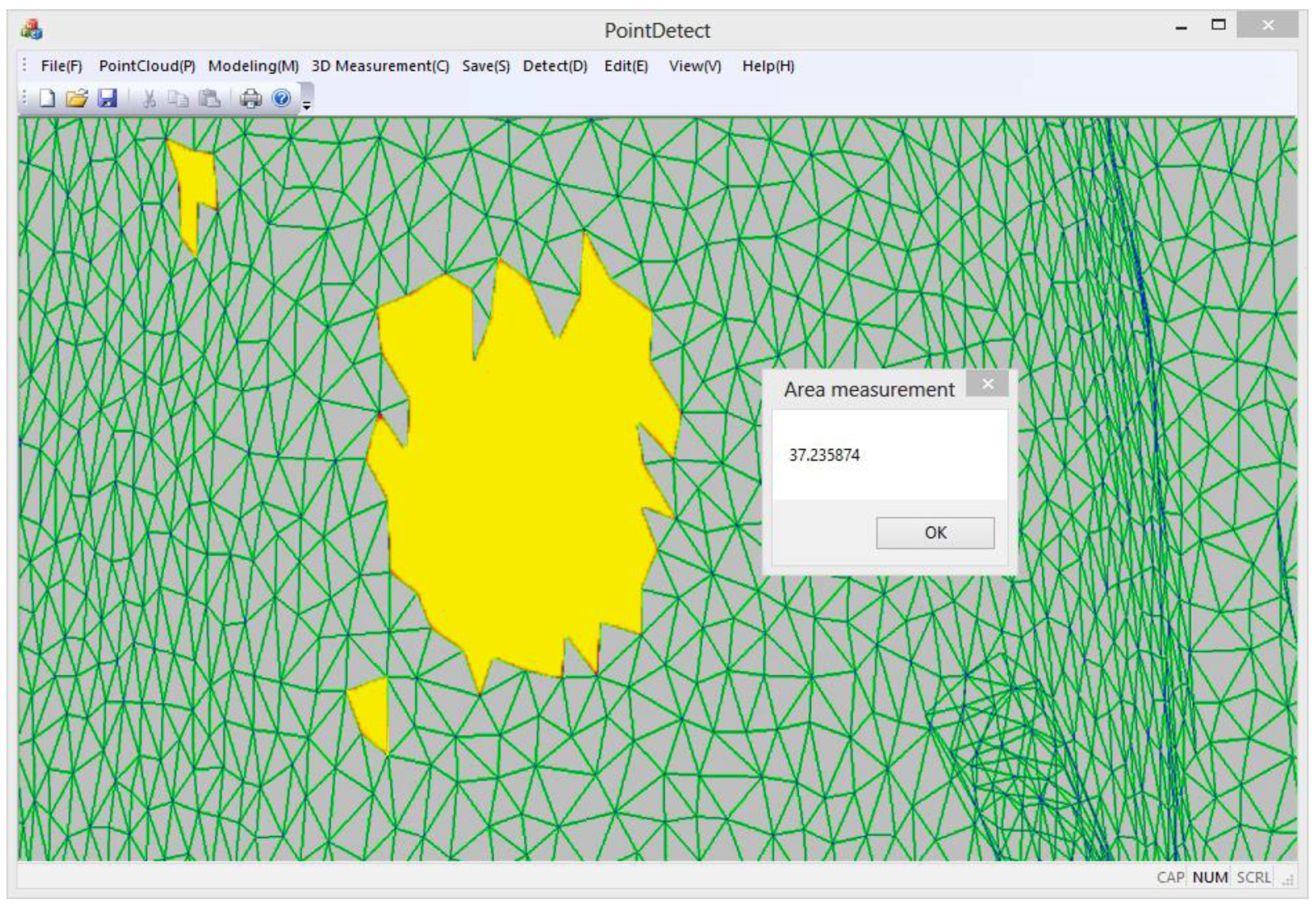
(2) Calculation of the damaged region based on a triangular mesh 

An irregular triangular mesh is a collection of many spatial triangles. To compute the area of the triangular mesh, we calculate the total areas of these triangles. Since the entire set of vertex coordinates are known, the side lengths of the triangles are also known. Therefore, the surface area of the irregular triangular mesh can be calculated according to Heron’s formula, which can be stated as follows.
If the side lengths of the ith triangle are ai, bi, ci, respectively, the perimeter pi of the ith triangle will be:
p i = a i + b i + c i
The area si of the ith triangle will be:
s i = 1 2 p i × ( 1 2 p i a i ) ( 1 2 p i b i ) ( 1 2 p i c i )
The total surface areas S of the model will be:
S = i = 1 n s i

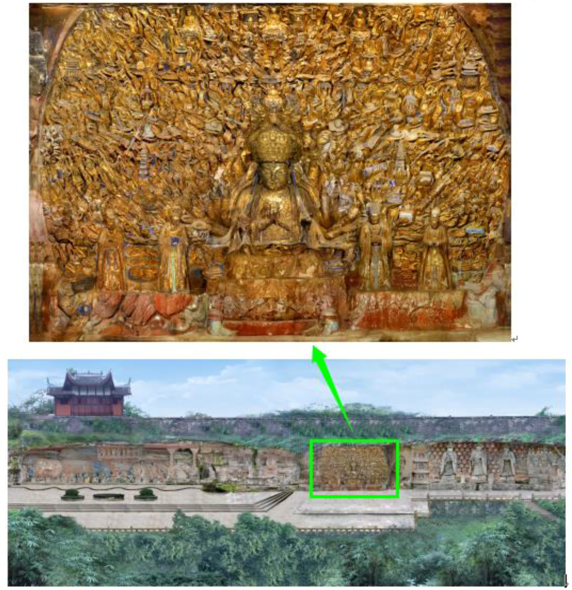
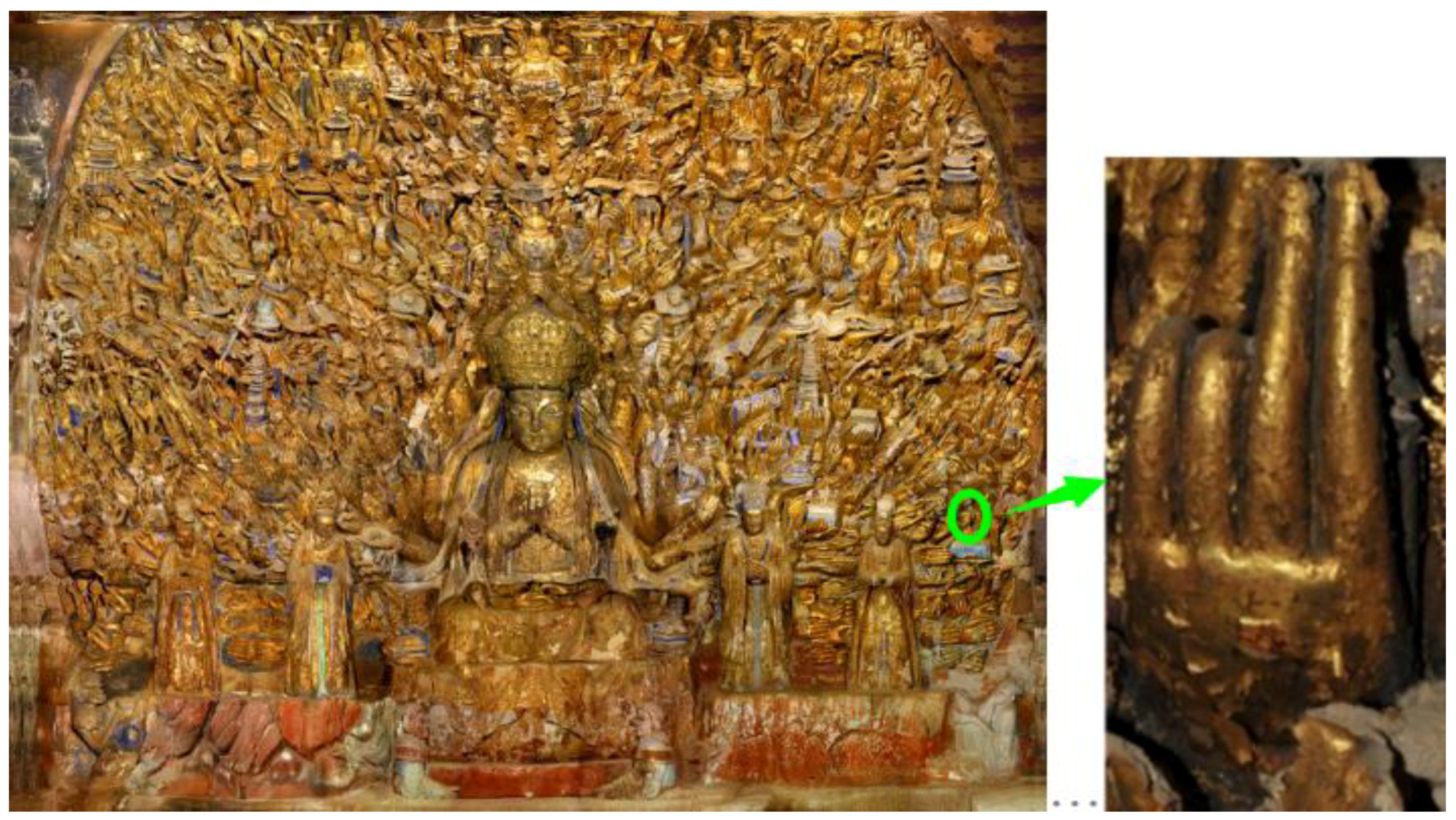
3. Research Area and Damage Detection

Carved during the Southern Song dynasty, the Thousand-Hand Bodhisattva Statue, located on the south cliff of the Dazu Baoding Mountain in Chongqing, China, is the largest cliff-carved Thousand-Hand Bodhisattva Statue in China (seen in Figure 11). Gold is overlaid across the entire surface of the statue, causing it to appear splendid and magnificent. However, after more than 800 years, the statue has suffered from various forms of damage. The gold foil on the surface has accrued serious damage. According to study statistics [28], 60% of the gold surface has faded and 57.8% of the gold foil in the center, the lower part of the statue has fallen off, and 43.9% of the upper gold foil has curled. Such damage not only seriously weakens the image, beauty, and artistic value of the statue, but also threatens the preservation and structural integrity of the stone. In order to test the proposed method, we carried out the restoration of gold foil on one hand and monitored it to obtain multi-temporal point cloud data.

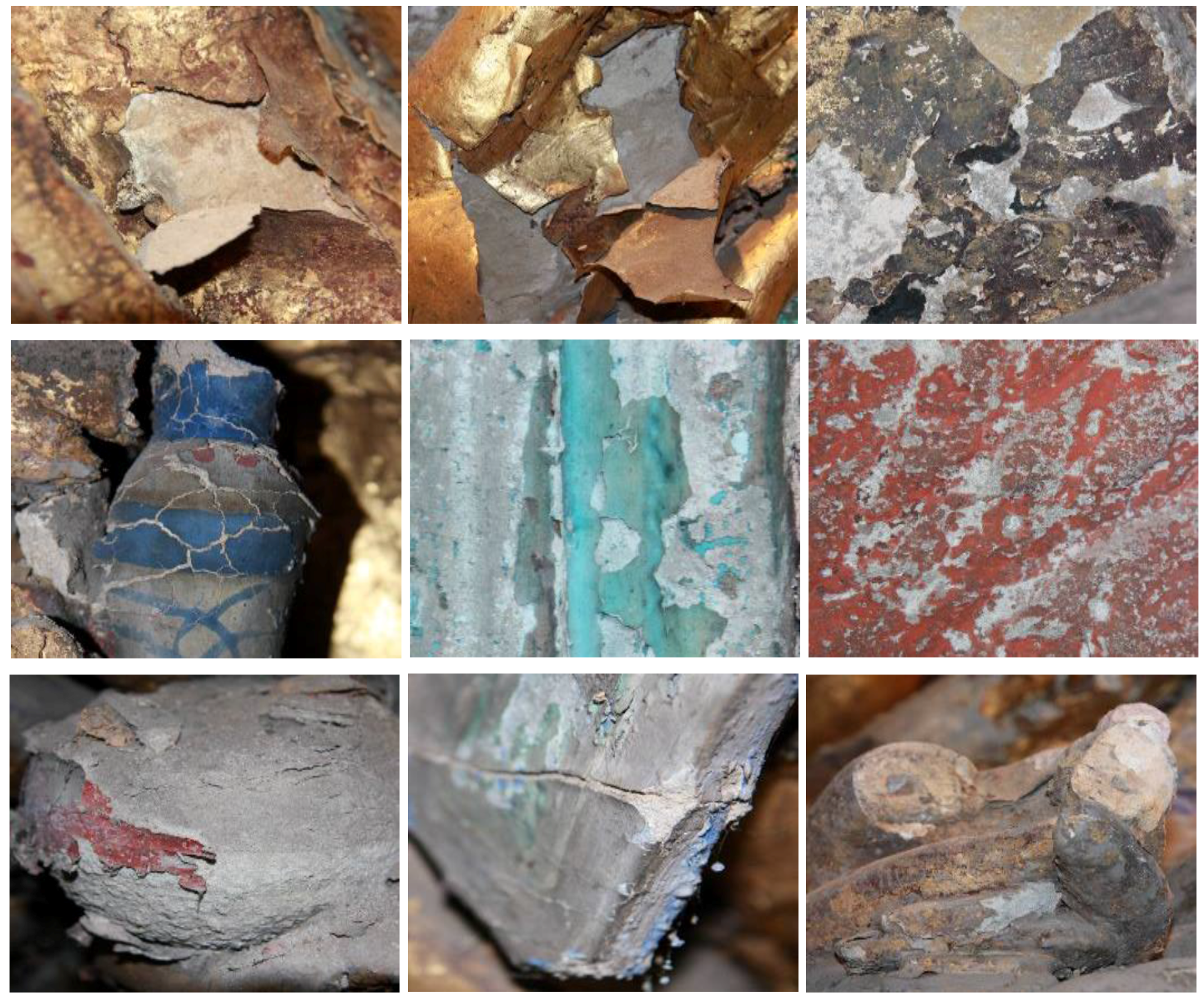
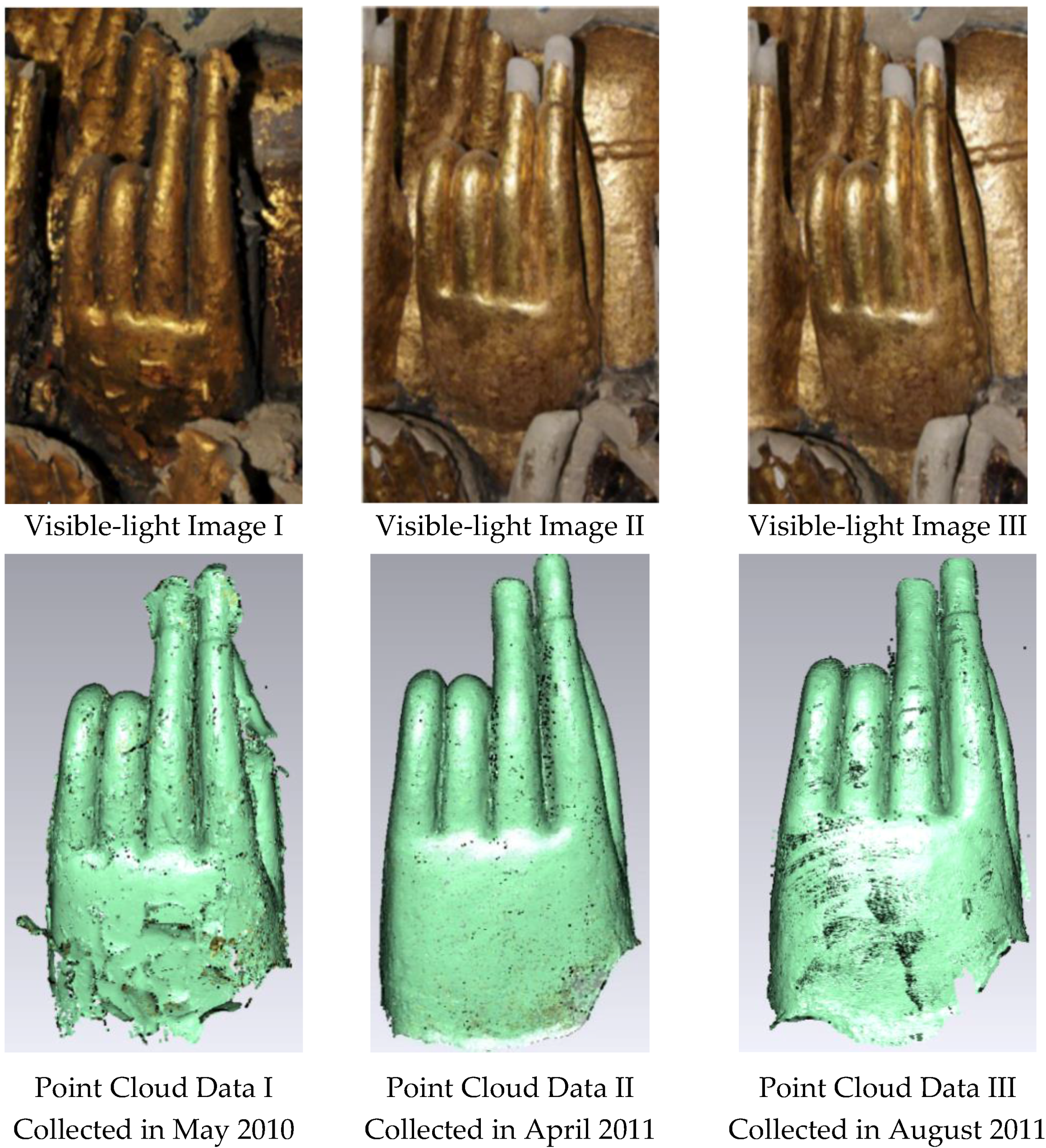
3.1. Experimental Data

The point cloud data in this experiment were collected by a portable Romer articulated arm scanner. The point cloud interval was 0.05 mm, and the single-point precision was 0.01 mm. In order to facilitate the collection of data and the monitoring of target spots, we selected hand 9-10-S2 (shown in Figure 12), which is located in the lower right corner of the statue, as the experimental object. The gold foil restoration for this hand was performed in October 2010. In order to monitor changes in the gold foil, multi-temporal data collection was carried out with the same scanner. Point cloud and texture data were collected at three different times, as shown in Figure 13 (the left point cloud was collected before restoration, and the others were after restoration). In order to unify the multi-temporal coordinates during data collection, we simultaneously performed collection of control-point data as well, i.e., the registration between datasets collected at different times and stations are ensured through some common points in all scans.

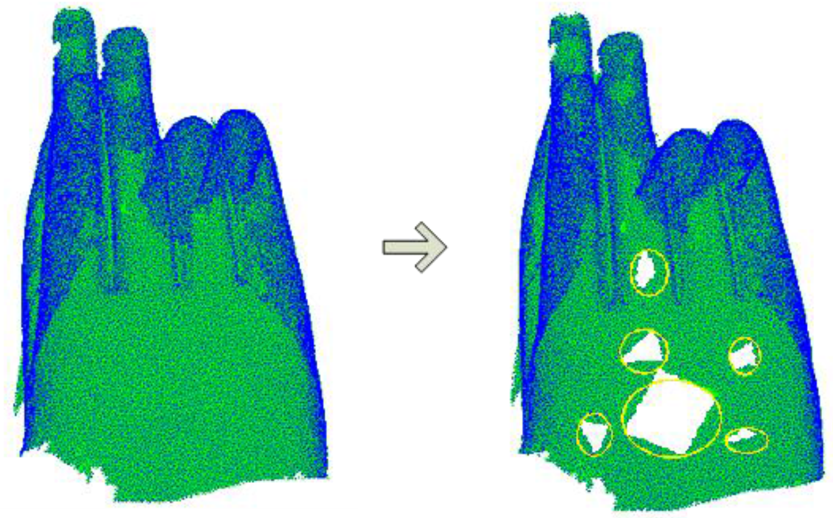
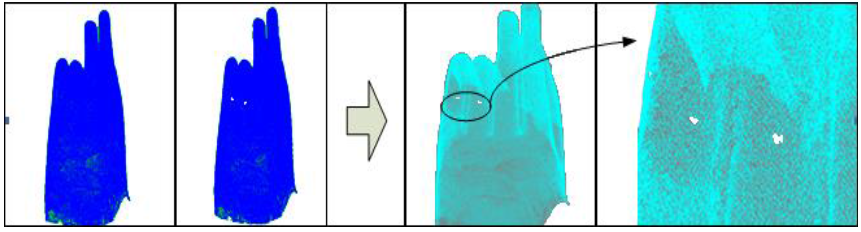
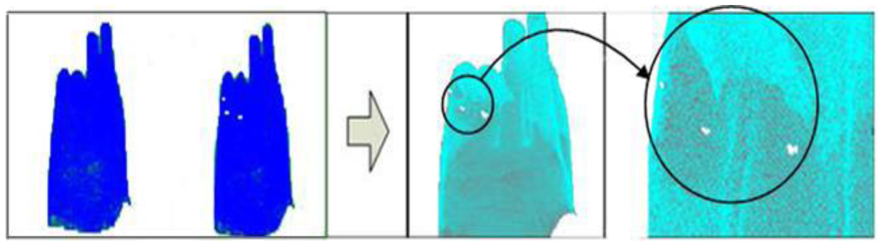
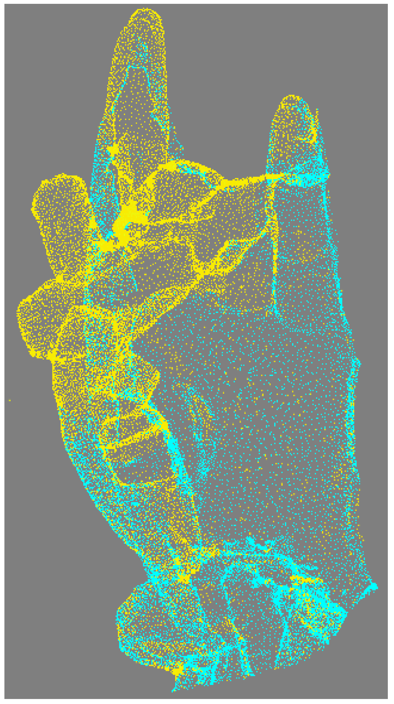
3.2. Damage Detection

We registered point cloud data with the Geomagic software (a 3D scanning and design system) and unified the coordinates by selecting stable control points. The final registration accuracy was 0.5 mm. Based on the accuracy of point cloud collection and registration, the damage detection threshold was set to 0.6 mm.
Secondly, we organized the point cloud data with a linear octree. From the above, we know that the threshold for damage detection is 0.6 mm. Because the point cloud data may emerge on the voxel boundary, it is more secure to set a threshold value that is much larger than the calculated threshold, such as 1.0 mm. In turn, the minimum bounding box can be worked out according to the point cloud data, as shown in Figure 14, and then reaches the layer number of splits. L was calculated to be 376.54 mm, and, according to Formulas (3) and (4), the number of rows in split κ can be obtained:
κ L P i x 376
Therefore, the split times should be less than 9, and the largest value is 8. Figure 15 shows the overall process that has been implemented during the experiment conducted to detect gold foil damage.

4. Results

4.1. Damaged Area Determination

In this paper, a new method based on a triangular mesh has been proposed to search for damaged regions. In order to verify the method and its algorithms, an experiment was conducted to compare and analyze results obtained from the same point cloud using two different techniques. These data included damage and were acquired by both manual identification and automatic identification using the proposed technique; they are shown in Figure 16 and Figure 17, respectively. The comparison demonstrates that results obtained using the two methods are similar and that the method using a triangular mesh to search for damaged regions is practicable.
The following results were obtained from the damage-detection experiment using the gold foil point cloud data obtained at three different times. Figure 18 shows the detection results from the first and second time. It is evident that the point cloud data obtained at these two times are almost identical within the disease-detection threshold. There is no obvious damage, except for those suspected spots on the third joints of the ring finger and thumb. Compared to the visible light images, there were no obvious changes, cracks, fall-offs, or other disease phenomena. Therefore, we can deduce that only gold foil hollowing occurred in this area. On-site investigation confirmed this prediction.
Figure 19 shows the detection results for the point cloud data obtained from the first and third time. It is evident there is obvious damage on the thumb and ring finger. Compared with the visible light images, we can see that gold foil hollowing did occur in this area and the on-site investigation did confirm this speculation.

4.2. Area Calculation

In order to apply the point cloud detection results to the preservation of this cultural relic, we need to know the surface area of the damaged gold foil in order to calculate the amount of gold needed in the restoration process. According to the damaged area calculation method described in Section 2, we calculated the detection results in the yellow region of the point cloud and obtained a damaged area of about 37.23 mm2, as shown in Figure 20.

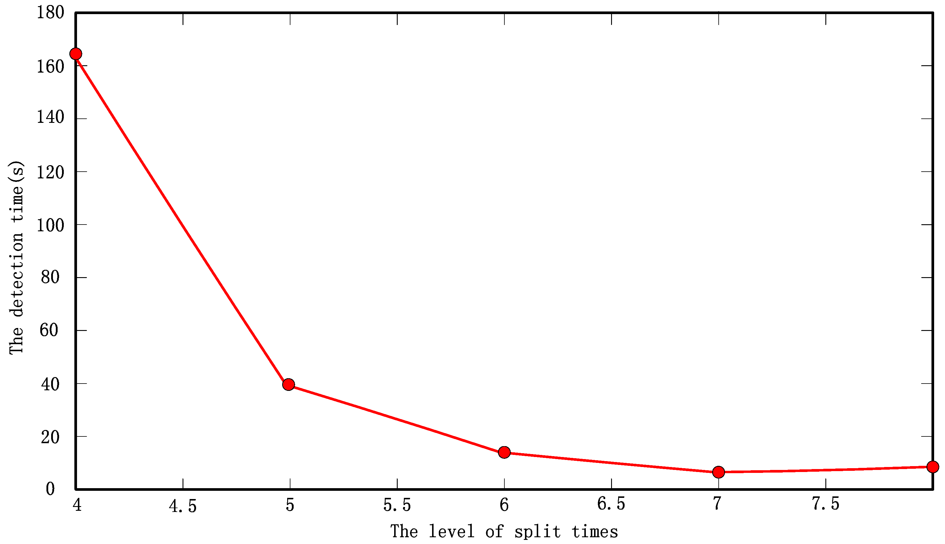
4.3. Retrieval Efficiency

As determined earlier, the layer split number should be less than 9, and the largest value is 8. Therefore, during the experiment, values ranging from 4 to 8 were successively assigned to the split level, and the system runtime was recorded (Table 1). Note that, in the table, 2 and 3 split levels are not included because their detection required too much time. It can be seen that, along with a continuous increase in the number of layers, the number of nodes increased by 8, and the time required by the index construction increased as well. However, the retrieval time quickly decreased. Therefore, between the encoding time and the retrieval time, a compromise is needed to achieve minimal detection time. From this experiment, we observe that the 7th level, which has a minimum total detection time, is the optimal choice. The relationship between the level of the split and the total detection time is shown in Figure 21.

5. Discussion and Conclusions

A method of using multi-temporal 3D laser scanning point cloud data to detect gold foil damage on stone carving relics was proposed and tested using one hand of the Thousand-Hand Bodhisattva Statue. The robustness and feasibility of this method were also demonstrated when it was applied to other hands. It has already been widely used in detecting changes in gold foil on the Thousand-Hand Bodhisattva Statue. The method allows for determination of a disease threshold by analyzing point cloud data errors. Efficient organization and management of the multi-temporal data was achieved using an improved linear octree encoding method, which converted octal numbers to numeric numbers. Identification and quantification of the damaged area was conducted using a triangular mesh. The calculated areas provided a good reference for gold foil restoration in stone relics. Furthermore, the detection software developed during this study allows for a contrasted view of point cloud data both before and after the virtual restoration. Figure 22 provides a vivid example, where the yellow points represent a virtual restoration, and the blue points represent the original data.
Although the proposed method can identify diseased regions in the gold foil based on an established triangular mesh, further efforts are needed to distinguish the types of gold foil damage that can be detected. Currently, this is done by expert technical personnel, which is expensive and inefficient. Further studies on the categories and characteristics of different forms of gold foil damage need to be conducted in order to improve the proposed method. These include developing a gold foil damage database and designing a matching electronic device that can automatically identify the category of the gold foil damage.
Damage results obtained by manual and automatic identification were compared and analyzed to demonstrate the robustness and feasibility of the proposed method. The manual identification of damaged area was done through direct measurement in point cloud and of the real damaged area on the hand. The precision assessment, which relates to many aspects and is very complex, was beyond the scope of this paper. Similarly, future studies should attempt to combine both 3D geometry and RGB color information in order to increase the accuracy of change area detection. Developments of this type will further improve upon the proposed method, making it a viable option for future relic preservation.

Acknowledgments

This paper is part of the National Program on Key Basic Research Project (973 Program, #2012cb725301), and is co-funded by the Beijing National Natural Science Foundation (No. 8111003). This work was also supported by a grant from the National Natural Science Foundation of China (No. 41171304). The authors would like to acknowledge and thank the Dazu Museum for their support in this work. The authors would like to thank Professor Songnian Li from Ryerson University, Canada for his constructive comments and guidance during the preparation of this manuscript.

Author Contributions

Conceived and designed the experiments: Miaole Hou; performed and analyzed the experiments: Shukun Li and Su Yang; provided technical guidance: Yuhua Wu, Yungang Hu, and Xuedong Zhang; wrote the paper: Lili Jiang.

Conflicts of Interest

The authors declare no conflicts of interest.

References

  1. Zhang, H.; Liu, Q.; Liu, T.; Zhang, B.J. The preservation damage of hydrophobic polymer coating materials in conservation of stone relics. Prog. Org. Coat. 2013, 76, 1127–1134. [Google Scholar] [CrossRef]
  2. Dellepiane, M.; Dell’Unto, N.; Callieri, M.; Lindgren, S.; Scopigno, R. Archeological excavation monitoring using dense stereo matching techniques. J. Cult. Herit. 2013, 14, 201–210. [Google Scholar] [CrossRef]
  3. Bitelli, G.; Girelli, V.A.; Marziali, M.; Zanutta, A. Use of historical images for the documentation and the metrical study of cultural heritage by means of digital photogrammetric techniques. In Proceedings of the CIPA XXI Symposium, Athens, Greece, 1–6 October 2007.
  4. Yastikli, N. Documentation of cultural heritage using digital photogrammetry and laser scanning. J. Cult. Herit. 2007, 8, 423–427. [Google Scholar] [CrossRef]
  5. Pesci, A.; Boschi, E.; Galli, C.; Boschi, E. Laser scanning and digital imaging for the investigation of an ancient building: Palazzo d’Accursio study case (Bologna, Italy). J. Cult. Herit. 2012, 13, 215–220. [Google Scholar] [CrossRef]
  6. Pesci, A.; Casula, G.; Boschi, E. Laser scanning the Garisenda and Asinelli towers in Bologna (Italy): Detailed deformation patterns of two ancient leaning buildings. J. Cult. Herit. 2011, 12, 117–127. [Google Scholar] [CrossRef] [Green Version]
  7. Pesci, A.; Teza, G.; Bonali, E.; Casula, G.; Boschi, E. A laser scanning-based method for fast estimation of seismic-induced building deformations. ISPRS J. Photogramm. Remote Sens. 2013, 79, 185–198. [Google Scholar] [CrossRef]
  8. Perroy, R.L.; Bookhagen, B.; Asner, G.P.; Chadwick, O.A. Comparison of gully erosion estimates using airborne and ground-based LiDAR on Santa Cruz Island, California. Geomorphology 2010, 118, 288–300. [Google Scholar] [CrossRef]
  9. Chen, B.Q.; Deng, K.Z.; Fan, H.D.; Hao, M. Large-scale deformation monitoring in mining area by D-InSAR and 3D laser scanning technology integration. Int. J. Min. Sci. Technol. 2013, 23, 555–561. [Google Scholar] [CrossRef]
  10. Girardeau-Montaut, D.; Roux, M.; Marc, R.; Thibault, G. Change detection on point cloud data acquired with a ground laser scanner. In Proceedings of the ISPRS Workshop “Laser scanning 2005”, Enschede, The Netherlands, 12–14 September 2005; pp. 30–35.
  11. Wawrzyniec, T.F.; McFadden, L.D.; Ellwein, A.L.; Grant, M.; Louis, S.; Joe, M.; Peter, F. Chronotopographic analysis directly from point-cloud data: A method for detecting small, seasonal hillslope change, Black Mesa Escarpment, NE Arizona. Geosphere 2007, 3, 550–567. [Google Scholar] [CrossRef]
  12. Lv, Z.; Kang, Z.Z. Change detection of buildings based on terrestrial laser scanning data. Geomat. Inf. Sci. Wuhan Univ. 2011, 36, 1284–1289. [Google Scholar]
  13. Wu, Y.H.; Hou, M.L.; Zhang, Y.M. Application of 3D laser scanning technique in the conservation of geotechnical cultural relics in China. In Proceedings of the 2011 Second International Conference on Digital Manufacturing & Automation (ICDMA), Zhangjiajie, China, 5–7 August 2011.
  14. Yüceer, H.; İpekoğlu, B. An architectural assessment method for new exterior additions to historical building. J. Cult. Herit. 2012, 13, 419–425. [Google Scholar] [CrossRef]
  15. Arbacea, L.; Sonninob, E.; Callieri, M.; Dellepiance, M.; Fabbri, M.; Idelson, A.L.; Scopigno, R. Innovative uses of 3D digital technologies to assist the restoration of a fragmented terracotta statue. J. Cult. Herit. 2013, 14, 332–345. [Google Scholar] [CrossRef]
  16. Gonzalez-Aguilera, D.; Muñoz, A.L.; Lahoz, J.G.; Herrero, J.S.; Corchón, M.S.; Carcía, E. Recoding and modeling Paleolithic caves through laser scanning. In Proceedings of the 2009 International Conference on Advanced Geographic Information System & Web Services (GEOWS), Cancún, Mexico, 1–7 February 2009.
  17. Bremer, M.; Rutzinger, M.; Wichmann, V. Derivation of tree skeletons and error assessment using LiDAR point cloud data of varying quality. ISPRS J. Photogramm. Romote Sens. 2013, 80, 39–50. [Google Scholar] [CrossRef]
  18. Abbas, M.; Ali, B.; Vetro, C. A Suzuki type fixed point theorem for a generalized multivalued mapping on partial Hausdorff metric spaces. Topol. Appl. 2013, 160, 553–563. [Google Scholar] [CrossRef]
  19. Yang, J.S. Organization and Visualization of Massive Multi-Source Point Cloud Data. Ph.D. Thesis, Wuhan University, Wuhan, China, October 2011. [Google Scholar]
  20. Tan, G.X. An optimization algorithm to construct a linear octree based on natural numbers. J. Wuhan Urban Constr. Inst. 1994, 11, 53–59. [Google Scholar]
  21. Rossi, L.; Torsello, A. Coarse-to-fine skeleton extraction for high resolution 3D meshes. Comput. Vis. Image Underst. 2014, 118, 140–152. [Google Scholar] [CrossRef] [Green Version]
  22. Yu, W.Y.; Li, Y.J.; Chen, Y.P.; Zhou, Z.D. A Mesh Simplification Method Based on Octree in Virtual Reality. Comput. Eng. Appl. 2006, 42, 34–36. [Google Scholar]
  23. Xiao, L.B.; Gong, J.H.; Xie, C.J. A new algorithm for searching neighbors in the linear quadtree and octree. Acta Geod. Cartogr. Sin. 1998, 27, 195–203. [Google Scholar]
  24. Liu, F.Z.; Li, Z.X.; Li, C.P.; Cao, Z.G. An linear octree based model for visualization of mining processes. In Proceedings of the 2011 Eighth International Conference on Fuzzy Systems and Knowledge Discovery (FSKD), Shanghai, China, 26–28 July 2011; Volume 4, pp. 2470–2474.
  25. Wang, M.; Tseng, Y.H. Incremental segmentation of LiDAR point clouds with an octree-structured voxel space. Photogramm. Rec. 2011, 26, 32–57. [Google Scholar] [CrossRef]
  26. Wang, M.; Tseng, Y.H. Automatic segmentation of LiDAR data into coplanar point clusters using an octree-based split-and-merge algorithm. Photogramm. Eng. Remote Sens. 2010, 76, 407–420. [Google Scholar] [CrossRef]
  27. Ali, T.A. Building of robust multi-scale representations of LiDAR-based digital terrain model based on scale-space theory. Opt. Lasers Eng. 2010, 48, 316–319. [Google Scholar] [CrossRef]
  28. Sun, H.Y. Research on Softening, Posting and Repairing the Gold Foil of the Dazu Thousand-Hand Bodhisattva Statue in Chongqing, China. Master Thesis, University of Science and Technology of China, Hefei, China, 2010. [Google Scholar]
Figure 1. Typical damage found in gold foil (fall-off, curling, cracking, etc.).
Ijgi 05 00060 g001
Figure 2. The overall technical process of the proposed method.
Ijgi 05 00060 g002
Figure 3. A geometric interpretation of partial Hausdorff distance.
Ijgi 05 00060 g003
Figure 4. Variational point cloud identification based on partial Hausdorff distance.
Ijgi 05 00060 g004
Figure 5. The KD tree subdivision in three-dimensional space.
Ijgi 05 00060 g005
Figure 6. Various structural subdivision renderings. (a) A regular quadtree subdivision rendering. (b) An adaptive quadtree subdivision rendering. (c) A KD tree subdivision rendering.
Ijgi 05 00060 g006
Figure 7. The quadtree structure.
Ijgi 05 00060 g007
Figure 8. The octree structure.
Ijgi 05 00060 g008
Figure 9. An irregular triangular mesh established by point cloud data.
Ijgi 05 00060 g009
Figure 10. A triangular mesh collection using variational points as the vertex.
Ijgi 05 00060 g010
Figure 11. An ortho-photo map of the Dazu Thousand-Hand Bodhisattva Statue and a panoramic of the partial view at Giant Buddha Bay.
Ijgi 05 00060 g011
Figure 12. The position of hand 9-10-S2 on the statue.
Ijgi 05 00060 g012
Figure 13. Visible light images and point cloud data for the tested hand at three different times.
Ijgi 05 00060 g013
Figure 14. Octree subdivision renderings. (a) A minimum enclosing frame of the point cloud; (b) the split times equal to 2; (c) the split times equal to 3.
Ijgi 05 00060 g014
Figure 15. The overall damage detection process.
Ijgi 05 00060 g015
Figure 16. Manual removal of the point cloud data, which included damage.
Ijgi 05 00060 g016
Figure 17. Automatic removal of the point cloud data, which included damage.
Ijgi 05 00060 g017
Figure 18. Results of data obtained from the first and second time (the white region is the suspected damaged region).
Ijgi 05 00060 g018
Figure 19. Results of data obtained from the first and third time (the white region is the suspected damaged region).
Ijgi 05 00060 g019
Figure 20. A damaged region calculation (the yellow region is the damaged region).
Ijgi 05 00060 g020
Figure 21. The relationship between the level of split times and the detection time.
Ijgi 05 00060 g021
Figure 22. A contrasted view of point cloud data before and after the virtual restoration.
Ijgi 05 00060 g022
Table 1. Detection efficiency.
Split LevelSegment NumberEncoding Time (s)Retrieval Time (s)Total Detection Time (s)
Level = 440960.407164.031164.438
Level = 532,7680.42239.54739.969
Level = 6262,1440.48512.12512.610
Level = 72,097,1520.9375.8286.765
Level = 816,777,2164.8134.2039.016
Level = 9134,217,728Insufficient memory

