Extracting Indoor Space Information in Complex Building Environments

1
Key Laboratory of Virtual Geographic Environment, Nanjing Normal University, Ministry of Education, Nanjing 210023, China
2
State Key Laboratory Cultivation Base of Geographical Environment Evolution (Jiangsu Province), Nanjing 210023, China
3
Jiangsu Center for Collaborative Innovation in Geographical Information Resource Development and Application, Nanjing 210023, China
4
College of Geographic Science, Nantong University, Nantong 226019, China
*
Author to whom correspondence should be addressed.
ISPRS Int. J. Geo-Inf. 2018, 7(8), 321; https://0-doi-org.brum.beds.ac.uk/10.3390/ijgi7080321
Submission received: 26 May 2018
/
Revised: 29 July 2018
/
Accepted: 7 August 2018
/
Published: 9 August 2018
(This article belongs to the Special Issue Building Information Modeling and 3D GIS Integration: From the Theoretical to the Practical)
Abstract
:Indoor space information extraction is an important aspect of reconstruction for building information modeling and a necessary process for geographic information system from outdoor to indoor. Entity model extracting methods provide advantages in terms of accuracy for building indoor spaces, as compared with network and grid model methods, and the extraction results can be converted into a network or grid model. However, existing entity model extracting methods based on a search loop do not consider the complex indoor environment of a building, such as isolated columns and walls or cross-floor spaces. In this study, such complex indoor environments are analyzed in detail, and a new approach for extracting buildings’ indoor space information is proposed. This approach is based on indoor space boundary calculation, the Boolean difference for single-floor space extraction, relationship reconstruction, and cross-floor space extraction. The experimental results showed that the proposed method can accurately extract indoor space information from the complex indoor environment of a building with geometric, semantic, and relationship information. This study is theoretically important for better understanding the complexity of indoor space extraction and practically important for improving the modeling accuracy of buildings.
1. Introduction
The integrated three-dimensional (3D) modeling of buildings’ indoors and outdoors, indoor positioning and space analysis, are inevitable trends for the future development of 3D digital cities, building information modeling (BIM), and geographic information system (GIS) [1,2,3]. An indoor space is a built environment that is separated from the natural environment with certain materials and technological methods for a purpose or function [4]. Indoor spaces, which generally contain specific usage function and clear spatial boundaries, are the main regions for modern humans to perform indoor activities related to work, leisure, and shopping [5]. Extracting indoor space information involves obtaining the functional regions of indoor space by identifying their boundaries from two-dimensional (2D) floor plans/3D BIM data. The result of indoor spaces extraction is a prerequisite for the application analyses of indoor navigation, environmental simulation, and building information management [6]. In addition, the extraction result plays a significant role in the extension of indoor 3D GIS [7].
Extraction approaches can be divided into three categories with respect to modeling indoor spaces [5,8]. In the first category, network model extracting methods abstract indoor spaces as nodes and the topological relationship between indoor spaces as edges to form a node-relation graph. Previous studies on network modeling based on a single 2D plan typically involved the Poincaré duality [9], media axis transformation (MAT)/centerline algorithm/shape skeleton [9,10,11], visibility graph [12,13], or combinations of the above [3]. To reflect the hierarchical structures of indoor spaces, Lorenz et al. [14] used hierarchical graphs that represent different levels of stories in buildings. In addition, a few studies divided an indoor room into smaller indoor spaces and built a network with smaller spaces to reflect the relationship between indoor spaces [15,16,17]. For example, Wallgrün [15] achieved complete division of an indoor space through the generalized Voronoi graph (GVG) and verified GVG-based route graphs suitable for robot navigation in an indoor environment. Several studies also explored the methods to extract indoor navigation network information based on BIM data [18,19,20,21]. For example, Tang et al. [19] described an automatic topology derivation from BIM to obtain an accurate navigation network. Isikdag et al. [21] presented a BIM-Oriented Model by using the advanced semantic and geometric information to support better indoor navigation. However, these studies mainly focused on the method of network generating from existing BIM indoor spaces rather than the building components. The advantages of the network model extracting method are its simple concept and its ability to generate networks that meet the basic requirements for indoor pathfinding navigation [22,23,24]. However, because the network model abstracts indoor space entities as a set of nodes, it loses the actual geometric information of indoor spaces and does not support the expression and analysis of continuous phenomena, such as indoor airflow motion and fire simulation, which must be performed in indoor space geometry [8].
In the second category, the regular grid/voxel model extracting method divides an indoor space into a set of regular grids/voxels associated with specific semantics. These grids/voxels generally have the same shape, such as rectangles, hexagons, and octagons. The structure and spatial dimension characteristics divide a 2D indoor space into grids [4,25,26] and a 3D indoor space into voxels [8,27,28,29]. Li et al. [4] discretized 2D indoor spaces into grids that could not only calculate the shortest path for indoor navigation but also supported the simulation and expression of indoor air movement, fire models, and other continuous phenomena. Liu et al. [27] built a sparse 3D voxel index for large-scale BIM data to present a real-time and light weighting Web visualization system. Xiong et al. [8] divided 3D indoor spaces into voxels and extracted an indoor space from a building model. However, the granularity of discrete grids/voxels determines the accuracy of indoor space modeling. When the size of a selected grid unit is extremely large, the boundaries and details of the indoor space cannot be accurately expressed. Moreover, for a large building with a comprehensive commercial architecture, a large number of grids can cause the problem of low efficiency for the analysis and calculation of an indoor space [4,8,26].
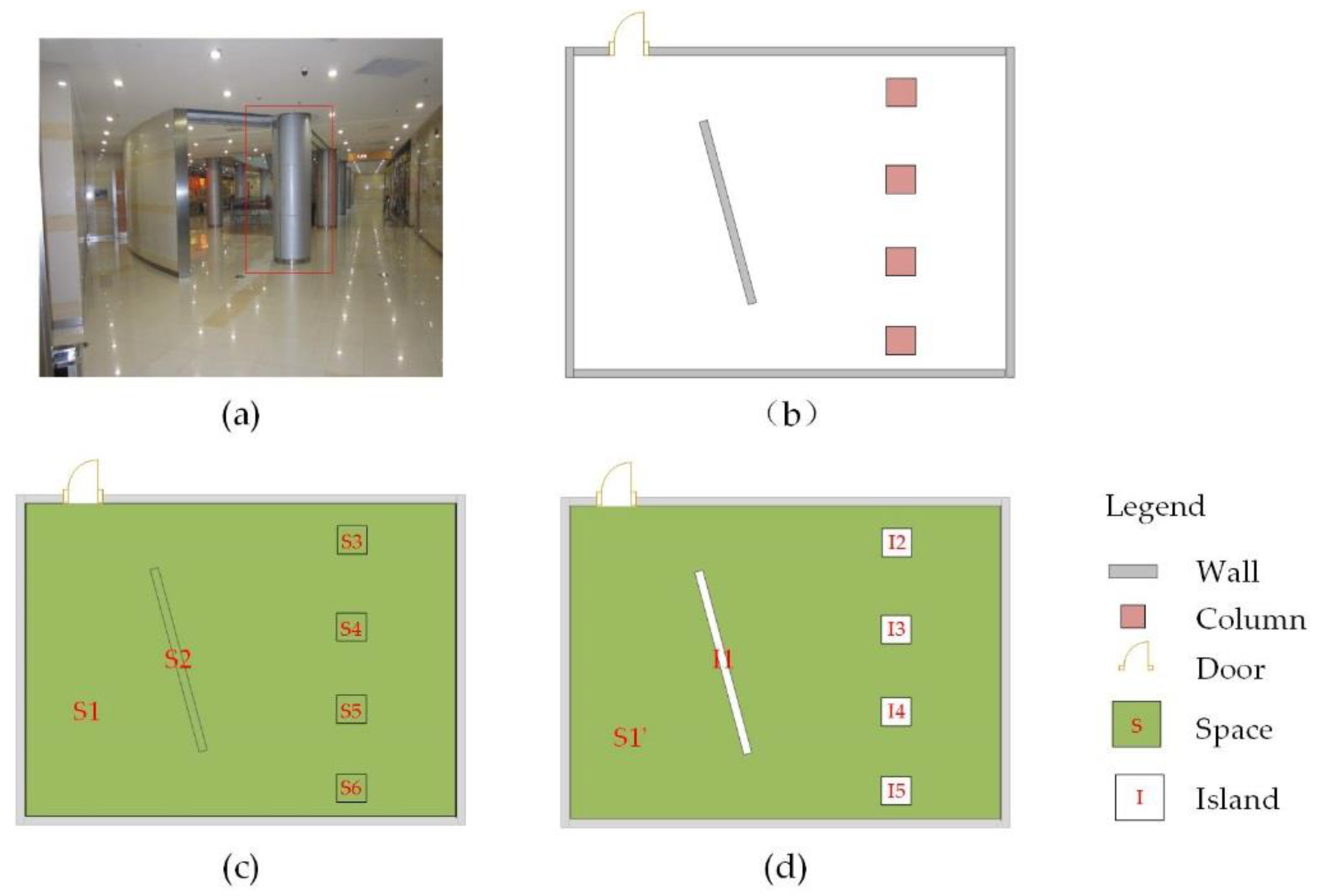
In the third category, the space entity model extracting method considers an indoor space as an entity with accurate semantic and geometric information and identifies the spatial topological relationships among indoor space entities, such as connectivity and adjacency. Furthermore, the extraction results can be converted into an indoor space network model or a regular grid model and satisfy application analyses such as indoor pathfinding navigation, environmental simulations, and building information management. Simultaneously, the entity modeling of an indoor space can obtain accurate indoor space boundaries; hence, extraction accuracy is ensured [30]. Therefore, the entity method provides evident advantages in terms of accuracy for expressing indoor spaces. At present, indoor space entity extracting methods mainly identify a function space from a detected loop set, which is surrounded by an edge object. The loop set is obtained by searching in an object graph, which is converted from a 2D floor plan. The search-loop method has been adopted to determine boundaries of the indoor space entity and extract the indoor space of a building [30,31,32,33]. Zhu et al. [31] proposed an odd–even-based method to preprocess wall lines and used the loop search method to obtain an indoor space. However, modern large buildings have several complex situations with isolated components, such as columns to support a hall and walls to divide functional areas, as shown in Figure 1a,b. These isolated building components cannot form a closed loop. Thus, an extraction method based on a search loop from a plane space cannot accurately extract a single-floor indoor space (Figure 1c). Current BIM software, such as Autodesk Revit, can support the extraction of indoor space information. However, to deal with cross-floor spaces, Revit must manually specify the upper boundary of spaces and does not fully extract automatic cross-floor space [34].
In summary, existing methods have certain problems in extracting indoor spaces. First, the existing space entity model extracting method cannot solve the isolated building component situation. The extracting method based on the search-loop theory simply uses the components around the loop as the geometric boundary of an indoor space without considering its internal isolated components. Additionally, these building components play an important role in limiting indoor space. An indoor space can be extracted with more accurate geometry only when all boundary components, which define the boundaries of the space, are considered. In terms of the composition, the objects in the building can be divided into two categories, namely building components, such as walls and columns, and indoor spaces that are divided into different rooms and corridors [35]. The interior space of a building is partitioned by all boundary components. Therefore, there must be boundary and co-boundary relationships between the building components and indoor spaces. All single-floor indoor spaces can be obtained if the region occupied by all building components is subtracted from the interior region of the building. The region occupied by isolated components also exists as an internal island in the indoor space, as shown in Figure 1d. Second, existing BIM software cannot automatically extract the cross-floor spaces in modern large-scale buildings. Two adjacent single-floor indoor spaces are separated by a floor slab in the vertical direction, and a cross-floor space can be generated by reconstructing the connectivity relationship between several single-floor spaces.
Based on the above analysis, this paper presents a new automatic indoor space extracting method that models single-floor indoor spaces and cross-floor spaces in complex indoor environments. Typical situations, such as isolated components and cross-floor spaces, are significant factors that influence the extracting accuracy of indoor spaces. The method can overcome these typical situations and ensure the accuracy of the extracted indoor space. A concert hall containing isolated components and cross-floor spaces was used as the experimental object to verify the effectiveness and practicability of the proposed method for extracting the indoor spaces of large complex buildings.
The framework of this paper is as follows. Section 2 presents the basic idea and overall procedure of the indoor space entity extracting method. Section 3 describes the extraction method in detail. Section 4 presents the experiment and analysis. Section 5 discusses the results, and Section 6 concludes the paper.
2. Basic Idea and Overall Procedure
The basic idea of accurately extracting a single-floor indoor space is to consider all enclosed building components; this is because indoor spaces have complex isolated components. First, the boundary of a single-floor space is calculated based on building components, and the region enclosed by the outer contour of the single-floor boundary is obtained. Then, the entire space occupied by boundary components is subtracted from the outer contour region through the Boolean difference operation. The remaining spaces are single-floor indoor spaces, which are divided into a set of sub-regions based on the building components. The modeled single-floor spaces are used to reconstruct the boundary relationships between the building components and indoor spaces according to the intersection condition. To extract cross-floor indoor spaces, the symbol of holes in a floor slab is extracted and the up-and-down connectivity relationship between adjacent single-floor indoor spaces is identified. Eventually, a complex cross-floor indoor space can be constructed by reconstructing single-floor spaces and determining the up-and-down connectivity relationship.
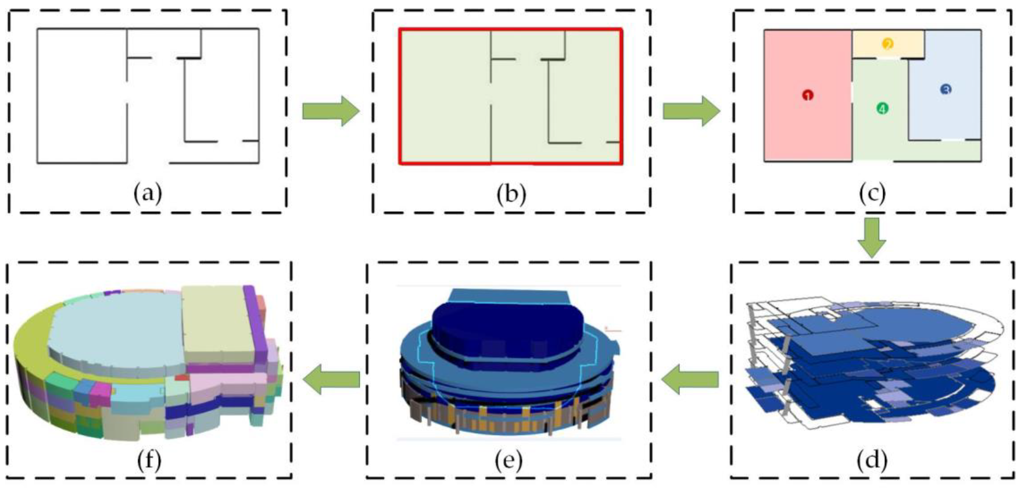
Spatial analysis technology is an advantage of GIS. In this study, the main geometric operations and relation judgments (e.g., intersect, contain, and within) are based on spatial analysis technologies with GIS. Therefore, we present a new method of extracting an indoor space and solve complex condition problems such as isolated components and cross-floor spaces. The overall procedure includes the following steps, as shown in Figure 2: Input data consist of all building components (Figure 2a). (1) The boundary of a single-floor space is calculated based on the building components (Figure 2b). (2) The single-floor indoor spaces extracting method considers the isolated components in the interior of a space (Figure 2c). (3) The downward connectivity of single-floor spaces is identified based on the holes in a floor slab. And Figure 2d highlights the single-floor spaces with downward connectivity. (4) The cross-floor space extracting method is realized. Figure 2e shows the result of the first floor modeling of cross-floor spaces. Figure 2f shows the output extraction results. The specific extraction steps are described in detail in Section 3.
3. Method
3.1. Calculation for the Indoor Space Boundary of a Single Floor
Building components are the basic entities that compose buildings. They are used alone or in combination with other building components to achieve the basic structure and functions of a building. The main building components include walls, curtain walls, columns, floor slab, doors, windows, roofs, and stairs. These components contain building elements that partition the interior space of the building. In this paper, building components that divide the interior space are referred to as boundary components. Boundary components are entities that define the boundary of the building indoor space. They act as the border between functional spaces within the building and between the interior space of the building and the external geographical environment. Extracting the semantic and geometric information of indoor space boundary components is the basic condition for indoor space extraction. Table 1 describes the semantic information of the following building components: wall, curtain wall, column, railing, and floor slab.
The boundary of a building’s indoor space is typically represented by the boundary components that geometrically restrict the indoor space. These components mainly include walls, columns, floor slabs, and railings. Figure 3 shows continuous wall components that remove openings and column components. Various types of boundary components collectively define the region of the building space. A boundary component can be defined as follows:
A boundary component (BC) is completely defined by its unique identifier (id), semantic description (SD), geometric information (GI), and relation information (RI). The boundary of a building’s indoor space is calculated as follows.
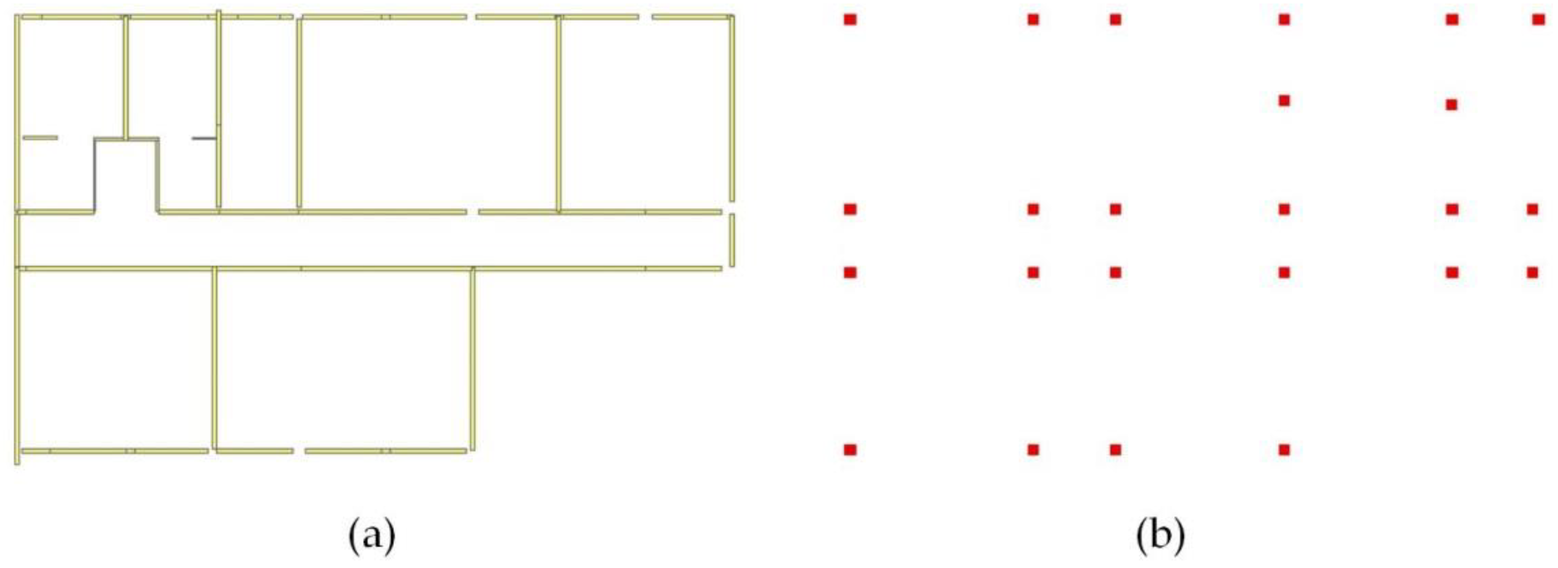
Step 1: Boundary components are selected according to whether they enclose and separate the space. According to this criterion, the selected boundary components include walls, columns, floor slab, and railings (Figure 4a).
Step 2: A set of geometric polyhedrons are obtained for each boundary component. The set expression of boundary components is as follows:
where BG is the set of building component geometries. is the geometry of the ith boundary member component, and n is the total number of boundary components.
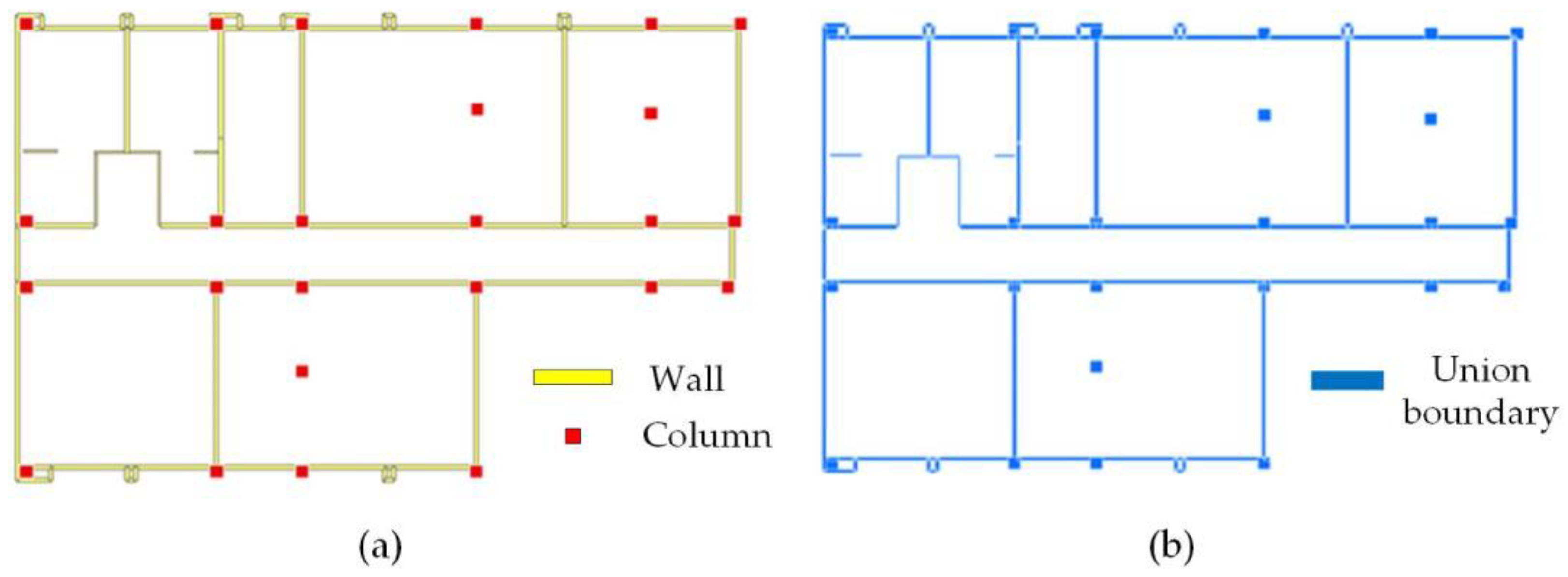
Step 3: Based on the geometry of boundary components acquired for a single floor, the Boolean union operation is performed on the geometry of the boundary components, and the union result of the boundary components of each indoor space is obtained (Figure 4b). The union result S can be described as follows:
3.2. Extracting Indoor Single-Floor Space of a Building
A building is generally organized according to floors. A single-floor space is defined as a space that only exists in one storey; the lower boundary of a single space is the floor slab of current storey and the upper boundary is the slab of upper storey. A floor plan view describes a single floor of a building on a 2D plane and can clearly show the interior structure. The single-floor plan is a horizontal section view that is along a slightly higher position compared to the windowsill. The single floor is cut with an imaginary horizontal plane; the upper part is removed, and an orthographic projection of the remaining part is created. In a building model, the outer border of the building is an intermediary between the architecture and geographic environment. The inner border of a building divides the functional subspaces.
The Boolean difference operation is used on the outer contour region of a single floor to subtract all components on the same floor. The remaining region contains indoor and outdoor spaces, which are separated by boundary components. Because the indoor spaces are enclosed by the boundary components of the building, they cannot be directly adjacent to the outer contour region of the floor. Therefore, the indoor and outdoor spaces are distinguished by detecting the adjacency between space geometry and the outer contour of the floor. The regions occupied by isolated components in the indoor space exist as islands; therefore, correct geometry of the indoor space is obtained. Figure 5 shows the process for extracting a single-floor space.
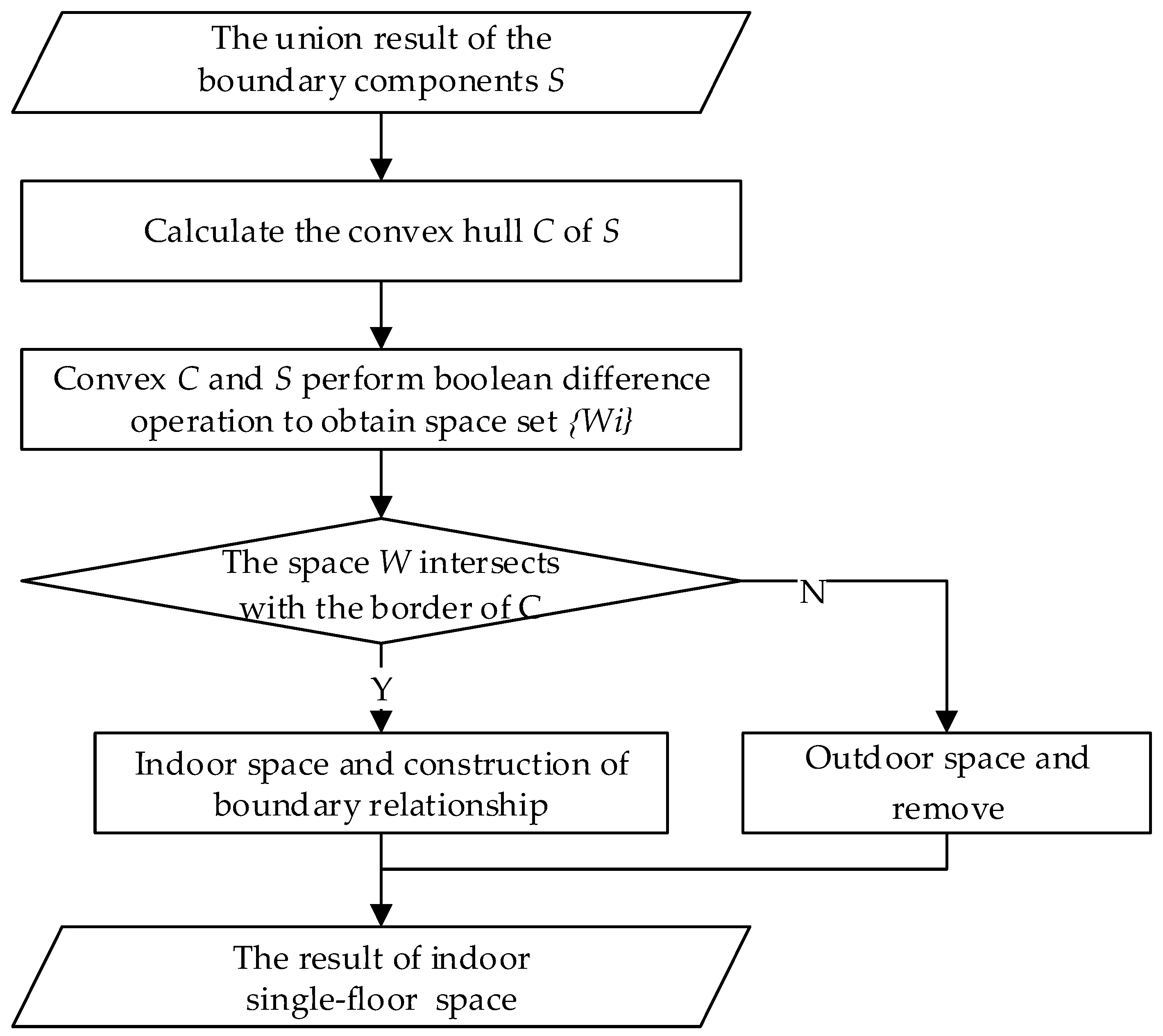
The specific extraction steps are given below.
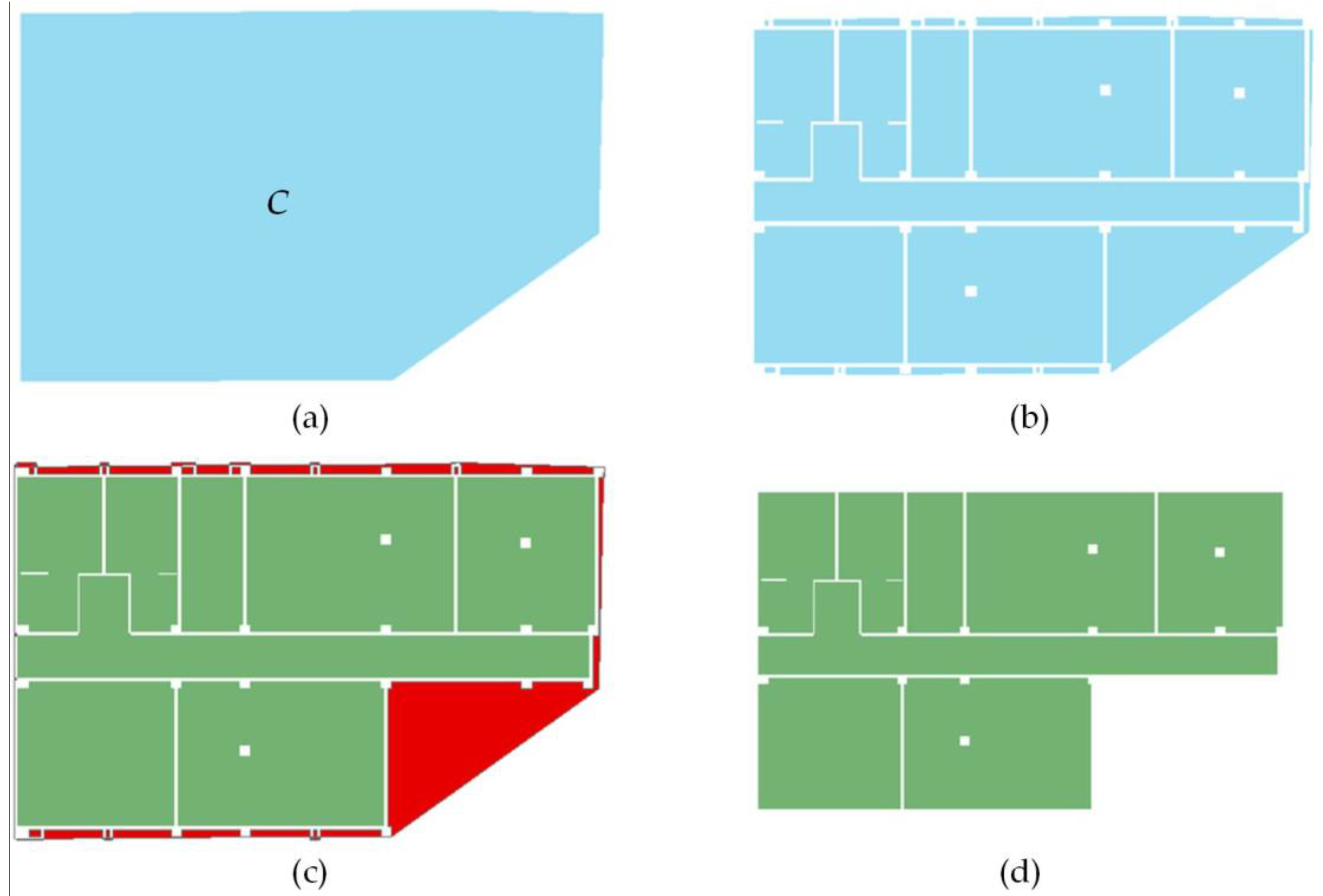
Step 1: Convex hull C is calculated for the union of results S (Figure 6a). 3D convex hull C is a polyhedron that surrounds all boundary components. As the convex hull is slightly larger, it does not affect the extraction of indoor spaces in this study. Therefore, the simplest calculation of the convex hull is to use the most external components.
Step 2: Convex hull C and union result S are used to perform the Boolean difference operation. Space geometry set {Wi} is obtained, which includes the indoor space enclosed by the boundary components and the outdoor space covered by boundary convex hull C. As shown in Figure 6b, the entire space is displayed in the floor plan view.
Step 3: Outdoor spaces are identified and removed. The above calculation results must distinguish and remove the outdoor spaces whose geometric shapes do not have clear semantics. The following formula is used for judgment:
If a space polyhedron intersects with the border of convex hull C, it belongs to the outdoor space and is removed. As shown in Figure 6c, the space colored in red represents the outdoor space. If the space polyhedron is away from the boundary of the convex hull C, it is the indoor space of the building (Figure 6d).
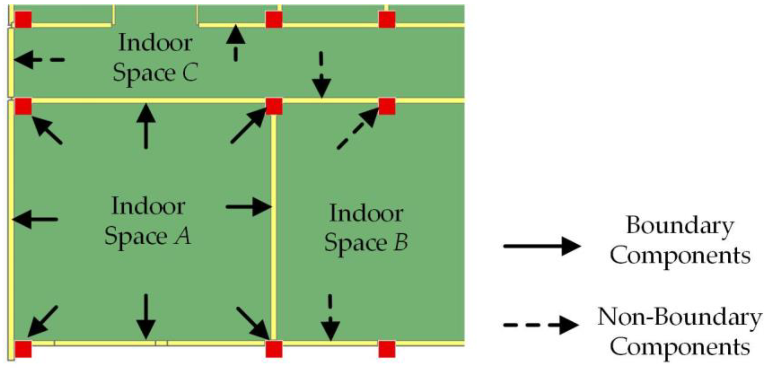
Step 4: The boundary relationship is constructed. All boundary components that geometrically intersect with the indoor space are queried, and the boundary relationship is built. Figure 7 shows single-indoor space A as an example. All boundary components that intersect with the border of A are queried, and the result is indicated by solid arrows. This set of boundary components is traversed to construct the boundary relationship between the space and boundary components of the building. The members that do not intersect with the border of A are excluded; these are indicated by dashed arrows.
3.3. Identifying the Downward Connectivity of Single-Floor Space
In complex buildings, indoor spaces can span multiple floors, such as atriums and halls. The connectivity of a cross-floor space is used to indicate the multiple floor characteristics of this indoor space. The cross-floor space is reflected in all floors. When the indoor spaces are identified from a single floor, each floor generates a separate single-floor space because the cross-floor characteristics of the indoor space are not considered; each divided single-floor space contains connectivity. A cross-floor space is divided into several independent single-floor spaces that are not connected. Therefore, the geometry of the cross-floor space is not correct. After the extraction and modeling of the building’s single-floor spaces, the connectivity of the cross-floor space must be judged.
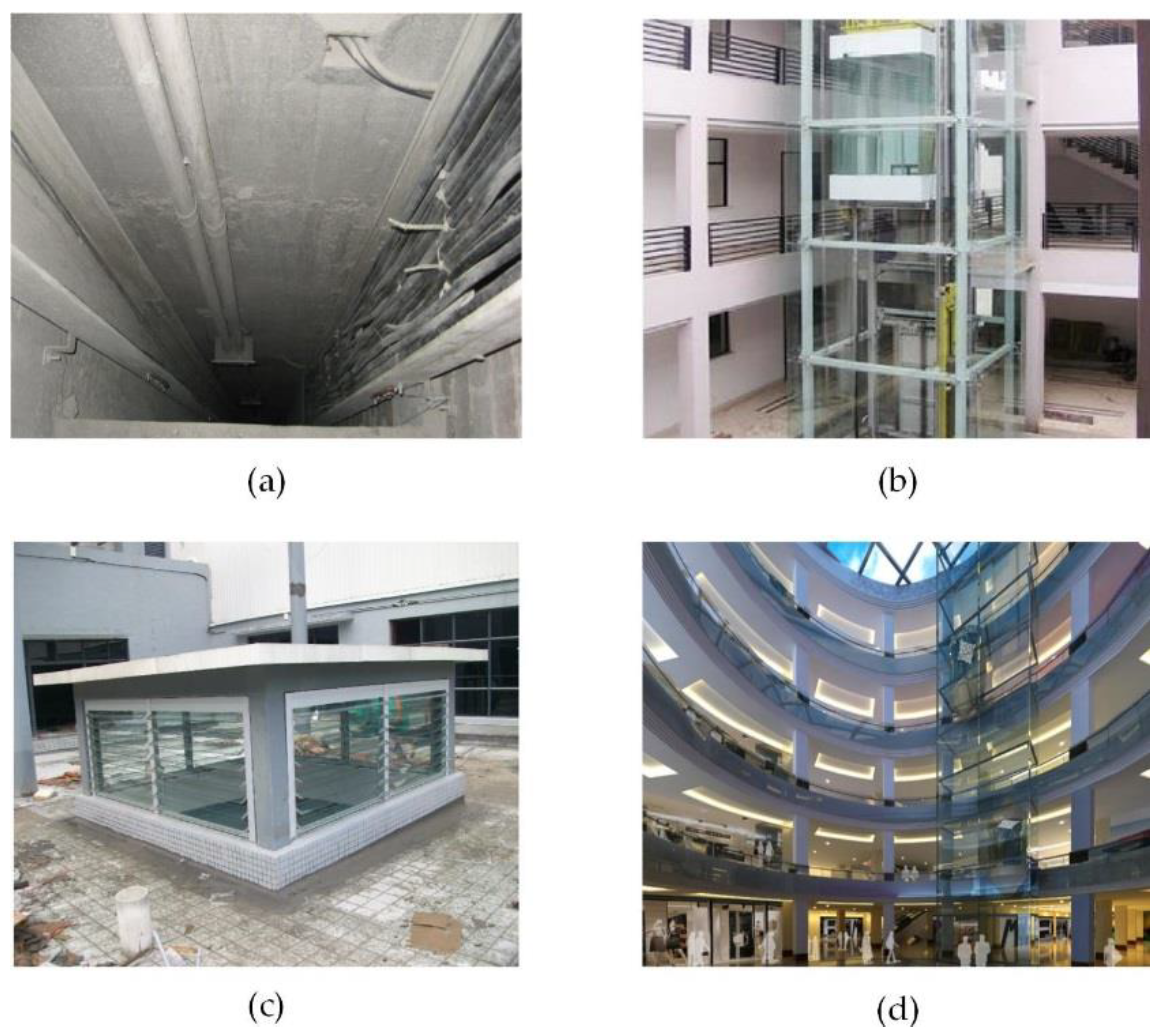
Cross-floor indoor spaces mainly include air duct wells, flue wells, elevator shafts, atria, pipe wells, and so on (Figure 8). Pipe wells provide a relatively safe and independent building space for water supply, drainage, electrical, heating, and air conditioning facilities (Figure 8a). For high-rise buildings, elevator shafts provide an essential space for facilities such as elevators and their tracks (Figure 8b). The main function of air ducts and flue wells is to exclude exhaust air, smoke, and other dirty air inside buildings while ensuring indoor and outdoor air flow (Figure 8c). An atrium is an indoor hall with multiple floors inside a building (Figure 8d).
A cross-floor indoor space has the following two characteristics:
- (a)
- Space accessibility. Because this space type spans multiple floors, there is no floor slab barrier in the vertical direction, and any floor of the building can be reached through this space.
- (b)
- Function specificity. A cross-floor space is generally designed to meet specific functional requirements of a building and has a specific role.
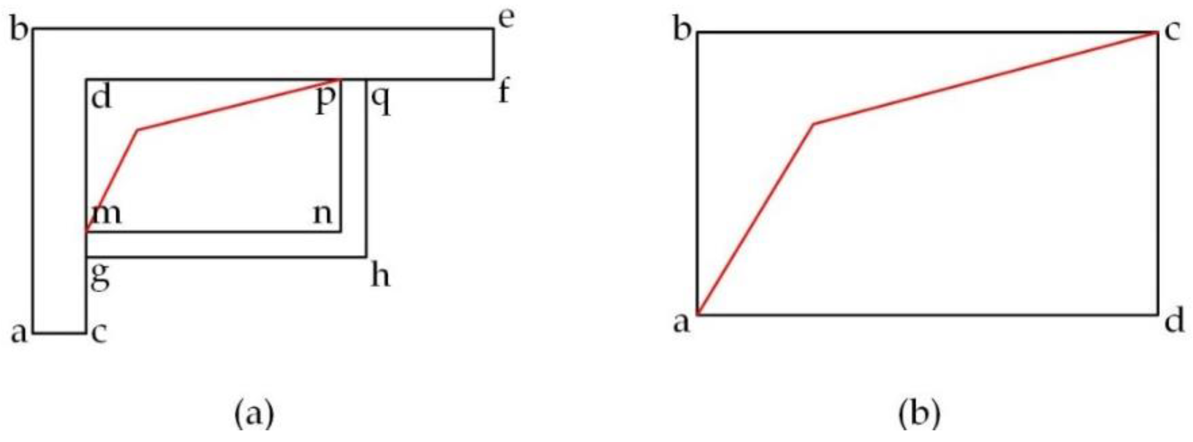
We consider the drawing standards in the fields of architecture and interior design. In a floor plan, a cross-floor indoor space is represented by specific legend symbols that are typically used for holes in floor slabs. As shown in Figure 9, the red polylines indicate the holes in a floor slab. There is no floor in the regions in which they are located. Hence, the upper and lower spaces of the two-story building are directly connected together to form a cross-floor building space.
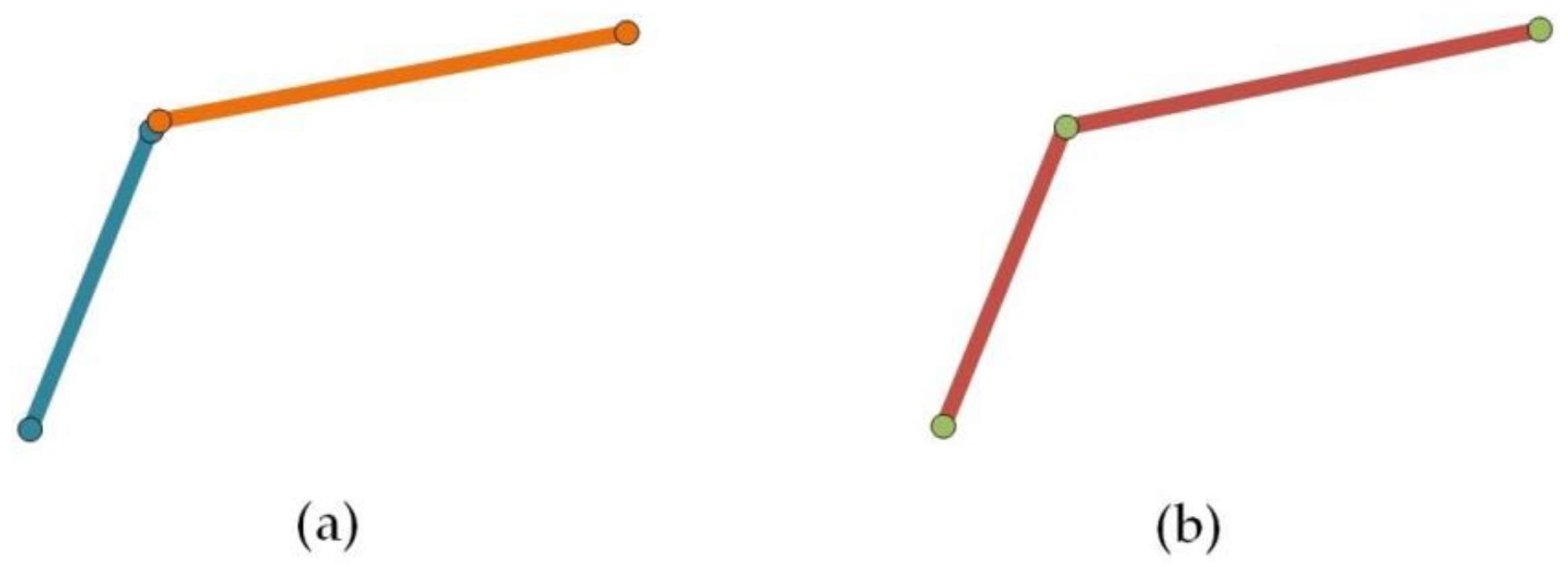
The polylines that represent the holes in the floor slab typically span across the entire cross-floor space and express the missing floor slab between the two floors. However, the hole symbol consists of discrete lines in a few cases. Thus, the hole symbol polylines must be rebuilt as shown in Figure 10. First, all lines in the hole symbol layer are extracted, and all geometrically discrete line segments in the hole symbol layer are used as input data (Figure 10a). Then, topological reconstruction is performed on all geometric line segments, and the line segments with the same endpoint are converted into a single polyline (Figure 10b). The resulting polyline is the hole symbol of the floor slab.
The analysis of a large amount of architectural plan data showed that the cross-floor space connectivity relationship can be transformed into identifying floor hole polylines in a drawing, and the downward connectivity relationship of the space is expressed in the upper floor plan. These polylines span the entire cross-floor space and consist of two straight lines at a certain angle. The cross-floor building space can be accurately identified by considering the spatial relationship between the geometries of the indoor space and polylines as the criterion for judging the downward connectivity of a building space.
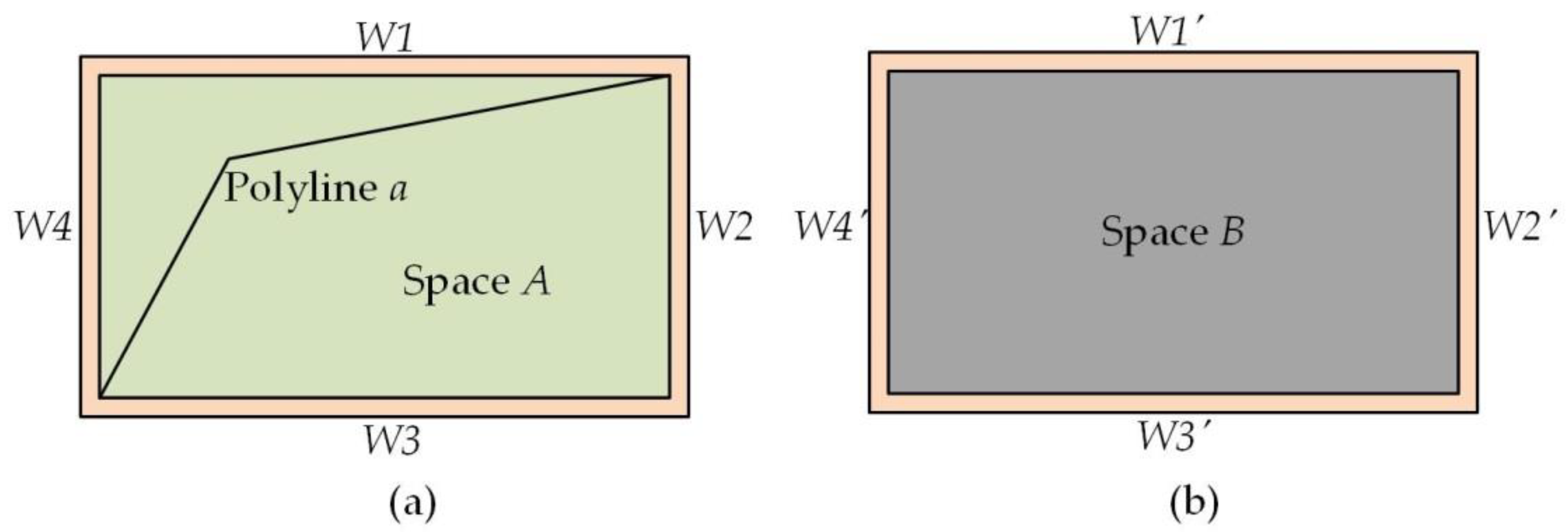
Figure 11 shows building space A enclosed by walls W1, W2, W3, and W4. Polyline a is the hole symbol for the floor slab. Building space B comprises the space boundary walls W1′, W2′, W3′, and W4′. Building indoor space A in Figure 11a contains hole polyline a. Therefore, A is a separate single-floor building space with downward connectivity. The indoor space B of the building in Figure 11b does not contain any polyline; hence, B is a single-floor indoor space with no downward connectivity.
3.4. Extracting Indoor Cross-Floor Space of a Building
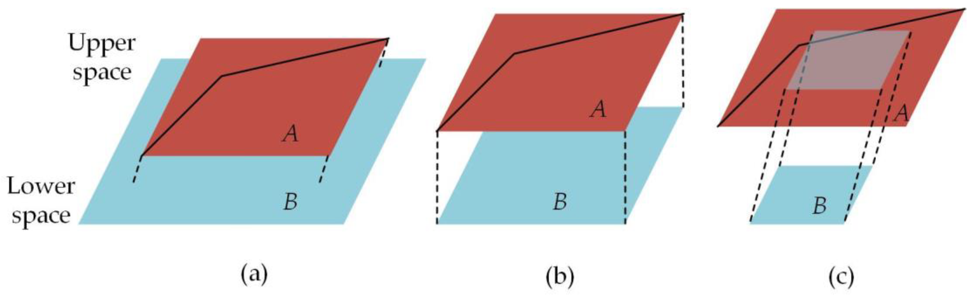
According to the method described in Section 3.3, if the building space on a certain floor contains a hole symbol polyline, its downward connectivity is determined. An upper space is directly connected to a lower space if a floor slab is absent between the upper and lower floors. There are generally three situations between the lower and upper spaces on a 2D horizontal projection plane, as shown in Figure 12.
- (a)
- A.area < B.area. The upper floor space is smaller than the lower floor space. The upper space projection is completely within the lower space.
- (b)
- A.area = B.area. The upper space is equal to the lower space. The upper space projection matches the lower space.
- (c)
- A.area > B.area. The upper space is larger than the lower space. The upper space projection covers the lower space.
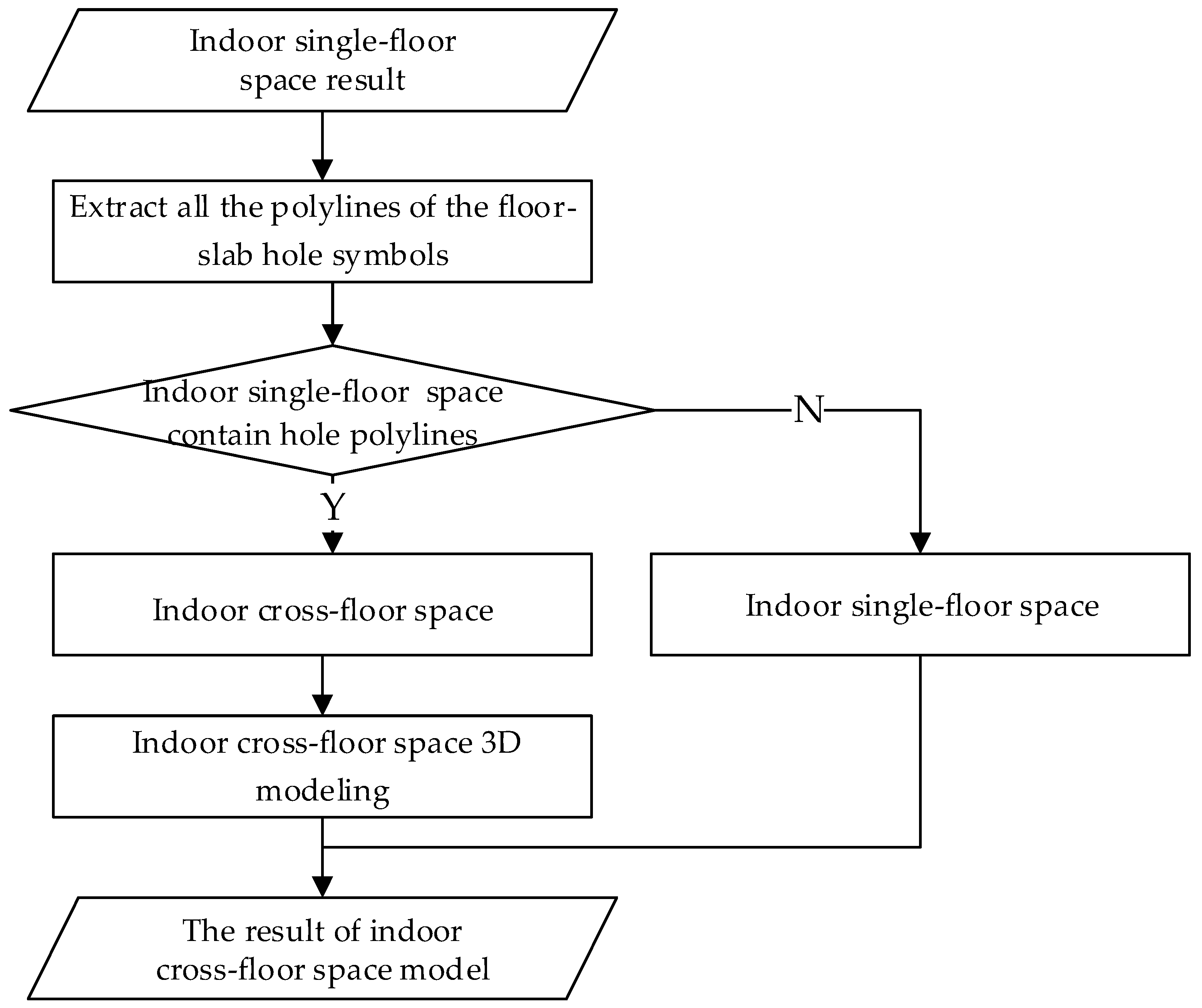
Figure 13 shows the specific process for extracting a cross-floor indoor space.
Step 1: The extracted building space for each single floor is input. We have described the extraction of all single-floor indoor spaces in Section 3.2.
Step 2: Polylines of the floor-slab hole symbols for each floor are extracted. If there is a hole symbol in the floor plan, we can confirm the existence of a hole in the 3D floor.
Step 3: It is verified whether there is downward connectivity, starting at the top floor of the building and checking each floor from top to bottom. If the indoor space contains a polyline hole symbol, the space is a downwardly connected cross-floor space; otherwise, it is a single-floor space.
Step 4: If the space is a cross-floor space, all spaces of the lower floor are searched. The space with the highest area overlap percentage (AOP) with the upper space projection is queried to find upwardly connected building spaces. The up-and-down connectivity relationship between the two spaces is built. The AOP is expressed as
where A is the upper space and B is the lower space. is the space projection to the lower floor, and is the area of the indoor space.
Using the above steps, all cross-floor spaces in single-floor building spaces are identified, and their up-and-down connectivity relationships are built. For the 3D modeling of cross-floor spaces, two or more 3D single-floor building spaces with upper and lower connectivity are combined in a geometric space. The specific steps for 3D modeling of a cross-floor building space are as follows.
Step 5: A pair of spaces with up-and-down connectivity relationships is obtained. After Step 4, we can obtain a set of up-and-down relationships that contain a set of two single-floor space IDs. We can find a pair of space entities based on the space ID.
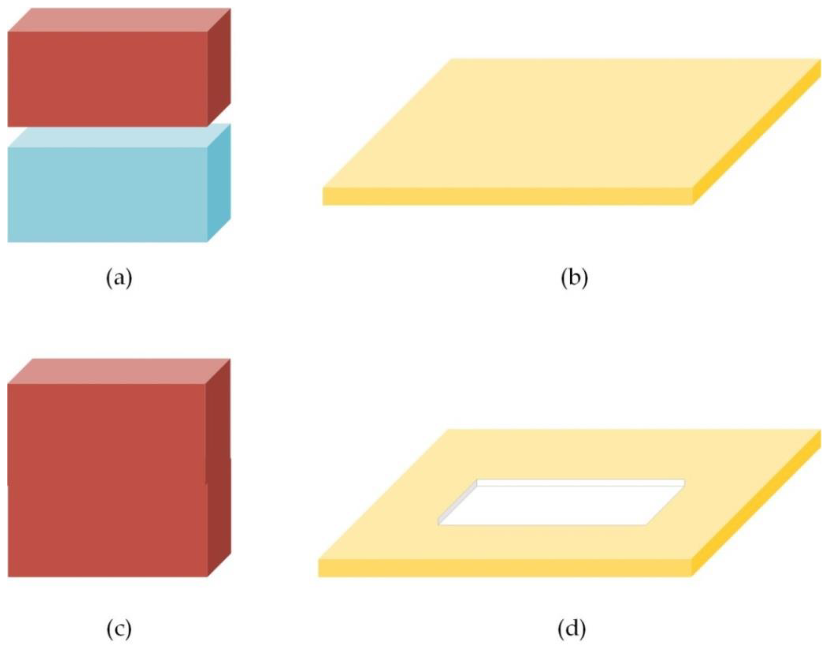
Step 6: Cross-floor 3D modeling. Figure 14a shows the extraction result for two single-floor spaces. If there is no connectivity between these spaces, the floor-slab 3D geometry is as shown in Figure 14b. However, if a pair of spaces has up-and-down connectivity, it is merged into a single cross-floor space through Boolean union operations (Figure 14c). The single cross-floor 3D spaces, which are connected by two single-floor spaces, passes through the hole in the floor slab as shown in Figure 14d.
Step 7: The result is output as an indoor cross-floor space. Finally, we obtain a cross-floor space with accurate semantics and geometry.
4. Case Study
The method of using laser-scanned data to extract indoor spaces has slow modeling and occlusion problems [36,37]. The field of architectural engineering is experiencing a transition from computer-aided design (CAD) to BIM. There are two methods of BIM construction, namely manual construction using existing BIM software directly and automated conversion from CAD to 3D BIM [31]. Planning, design, construction, and other departments possess large amounts of valuable building CAD data. The CAD data contain a large amount of building-related component information. Therefore, BIM 3D data, which are rebuilt based on CAD data, were used to model a building’s interior space in experiments.
4.1. Experimental Design
The experiments in this study were divided into two parts, i.e., extracting single-floor indoor spaces and extracting cross-floor spaces. Building components with semantic and geometric information were used as input data to model single floor-indoor spaces. The space boundary components included walls, columns, and railings. The search-loop method was compared with the single-floor space extraction method proposed in this paper. Cross-floor space connectivity was judged based on the modeled single-floor indoor spaces and the identification of hole symbols for a floor slab. Finally, the cross-floor space was modeled.
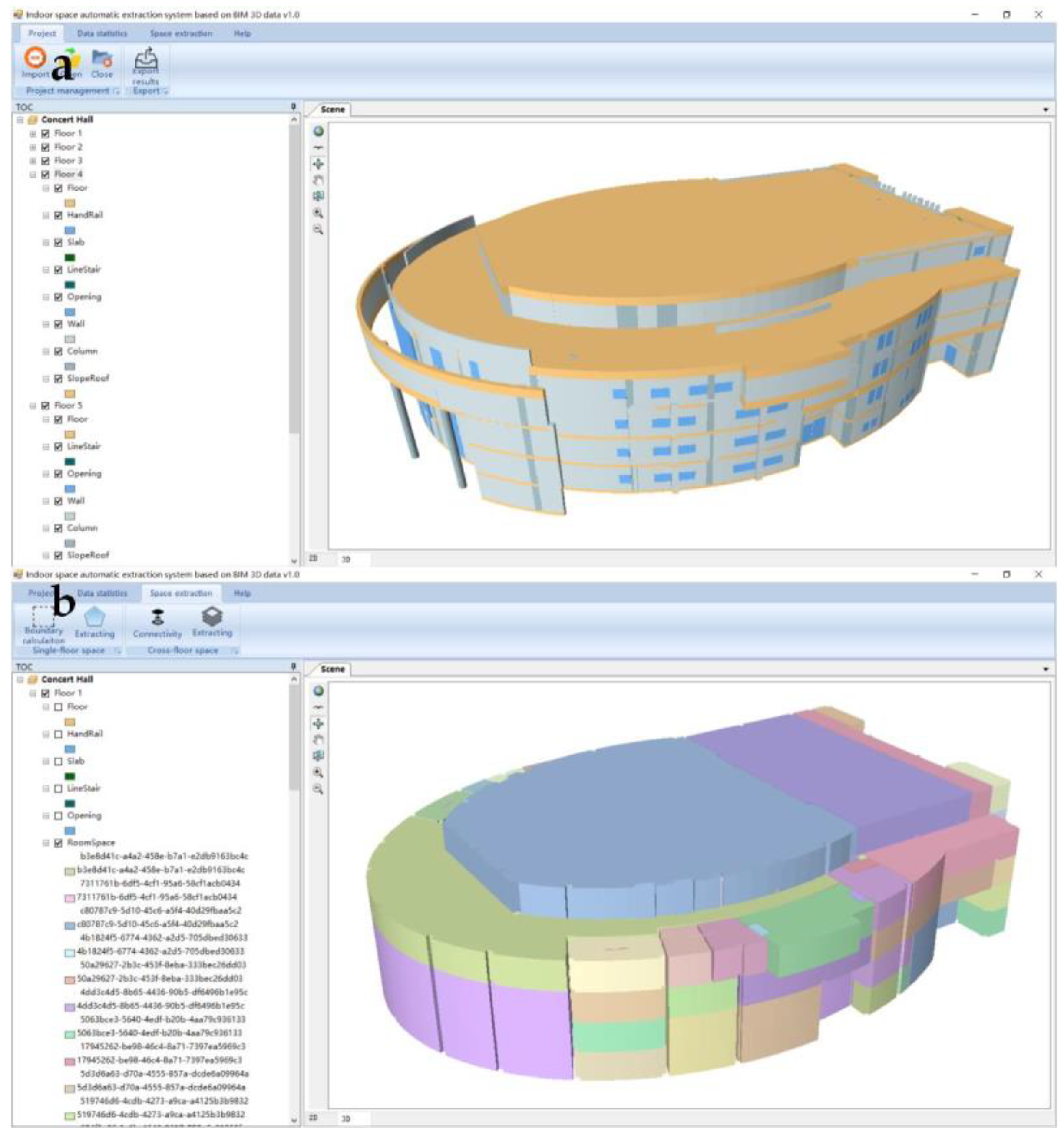
In the study, we chose the ArcGIS platform for integration with BIM data. In a BIM model, the building components are mainly represented by Constructive Solid Geometry (CSG) and Sweeping. We transformed CSG and Sweeping BIM into geometric representations using Multipatch in ArcGIS (Figure 15a). Furthermore, a set of attributes of the components was saved in the property sheet of Shapefile. The indoor space automatic extraction system was realized through C#. As shown in Figure 15b, our algorithm and program were embedded with GIS software using ArcEngine secondary development technology.
4.2. Experimental Data
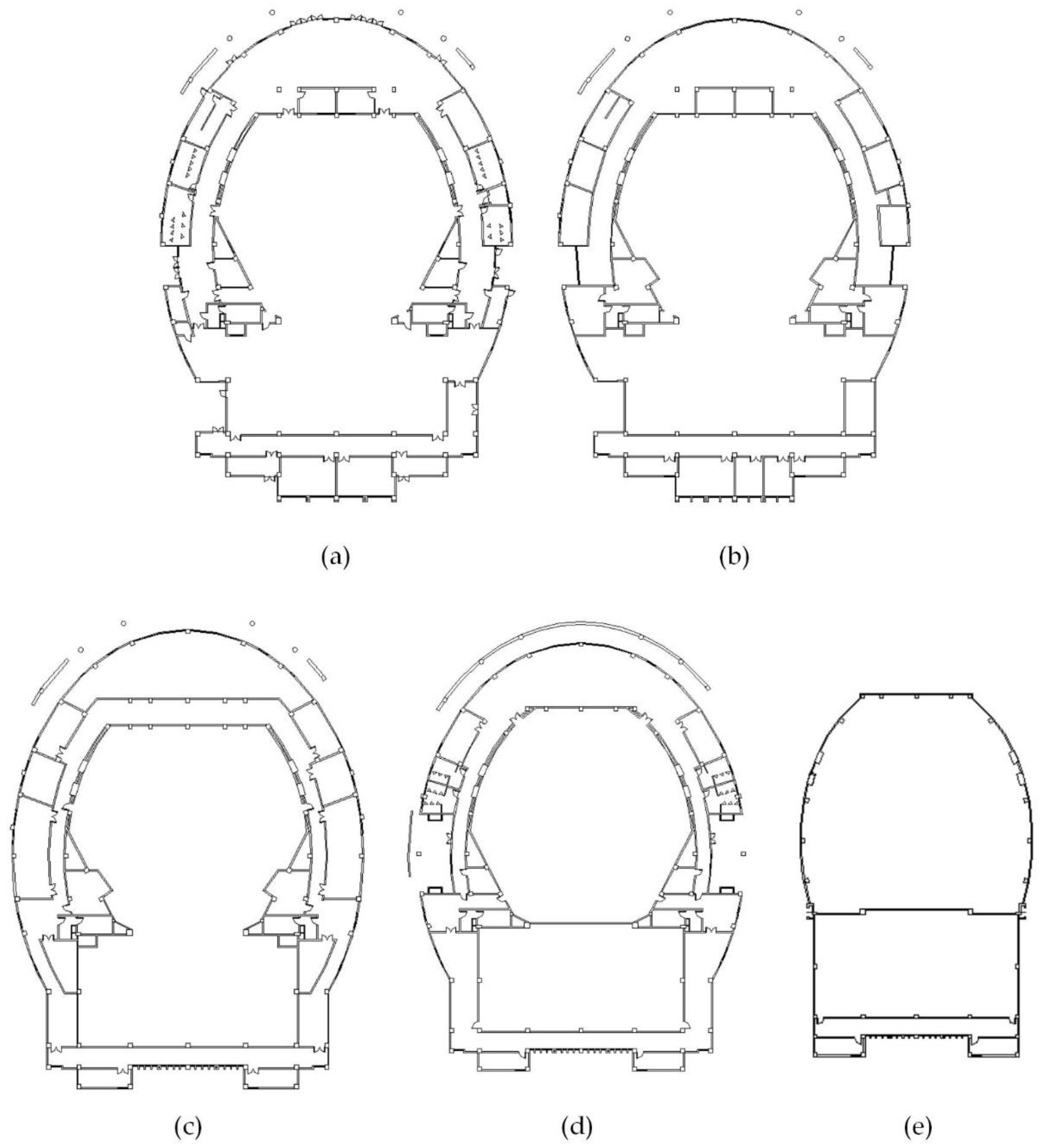
The proposed method was applied to the Concert Hall of Nanjing Normal University Zhongbei College in an experiment for verification, as shown in Figure 16. This is a public building with five floors (Figure 16a–e). This building is distinguished by containing the indoor complex environment required for the experiment. It contains a number of isolated columns and walls and includes several representative cross-floor spaces, such as the hallway, audience hall, performance stage, and duct well.
Table 2 presents the detailed floor information 2. In particular, the number of boundary components was obtained for each floor, including the number of walls, columns, railings, and total boundary components.
4.3. Experimental Results and Analysis
4.3.1. Indoor Single-Floor Space
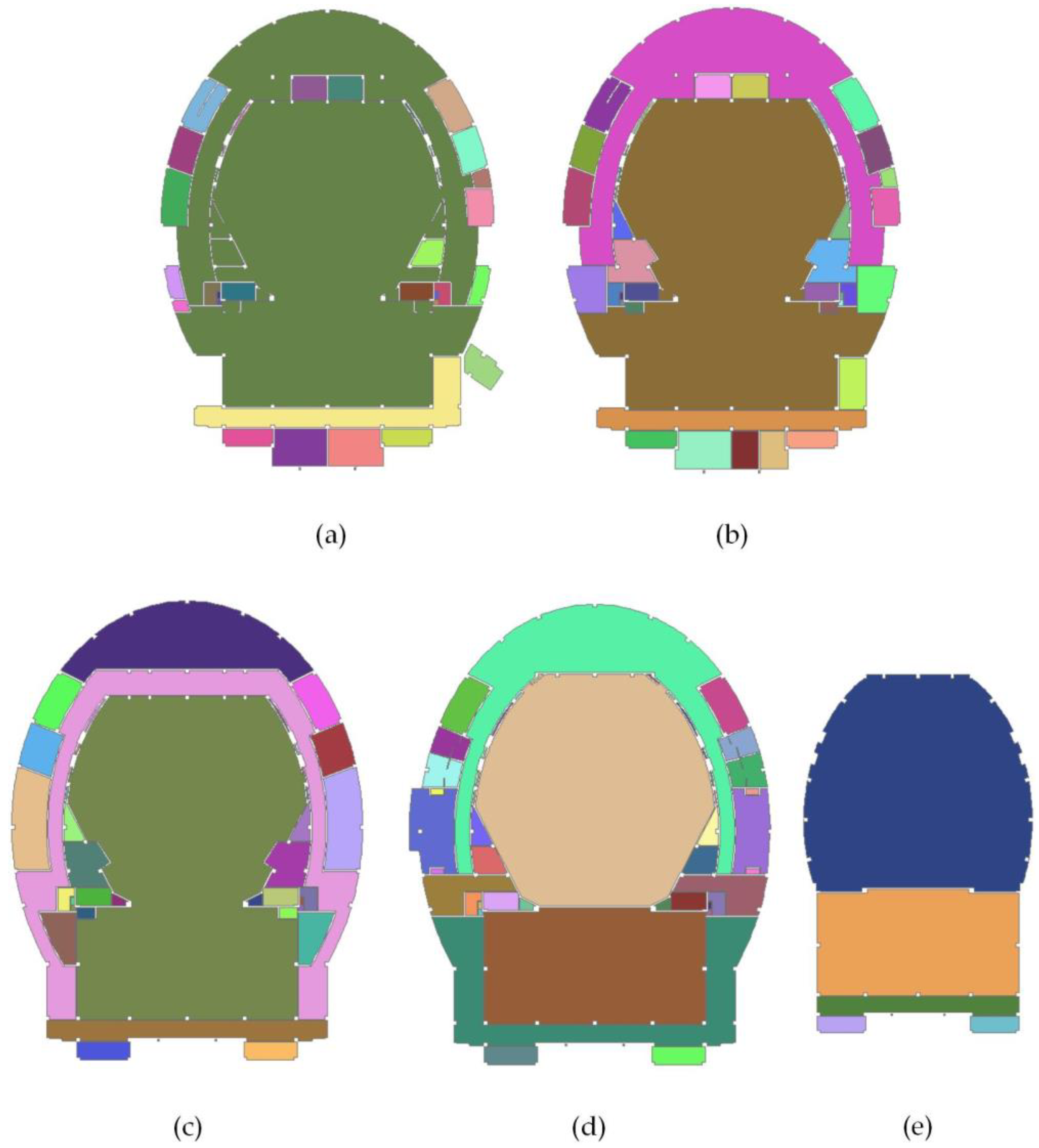
We used the concert hall building that contains isolated components to verify the correctness of single-floor space extracting method. As shown in Figure 17, 177 valid architectural indoor spaces are extracted from the concert hall building. In particular, the region occupied by all building components (as shown in Figure 16) is subtracted from the interior region of the building. The region occupied by isolated components exists as an internal boundary in the indoor space, as shown in Figure 17a. In each floor, the single-floor spaces are distinguished by colors. Table 3 presents the number of indoor single-floor spaces on each building floor.
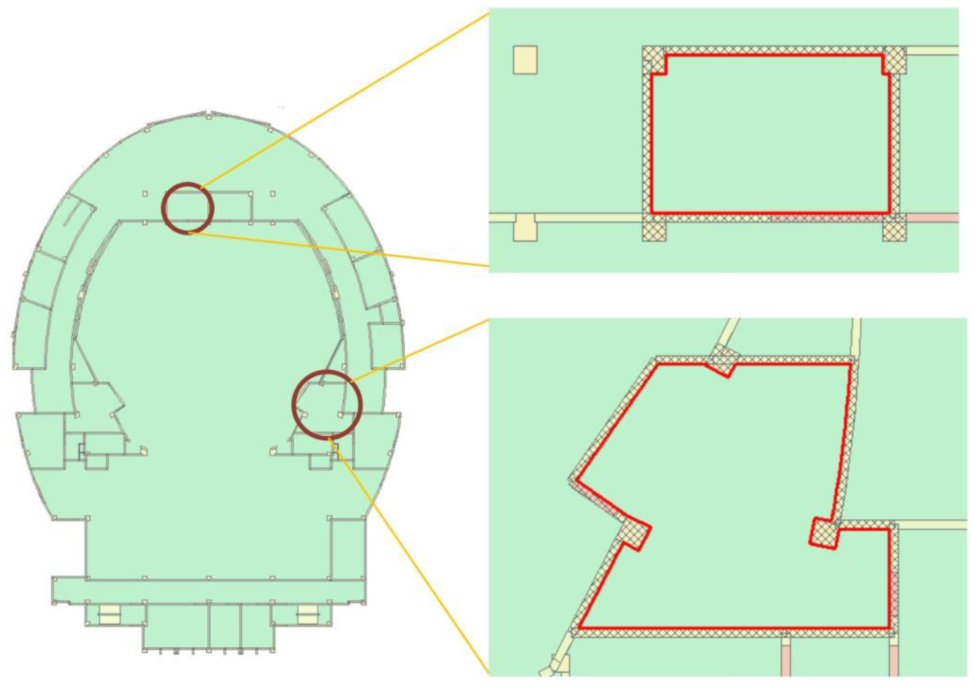
The reconstructed boundary relationship could be queried in real time as required. As shown in Figure 18, the red border shows the selected space, and the building components with boundary relationships are filled out with crosshatched lines.
4.3.2. Indoor Cross-Floor Space
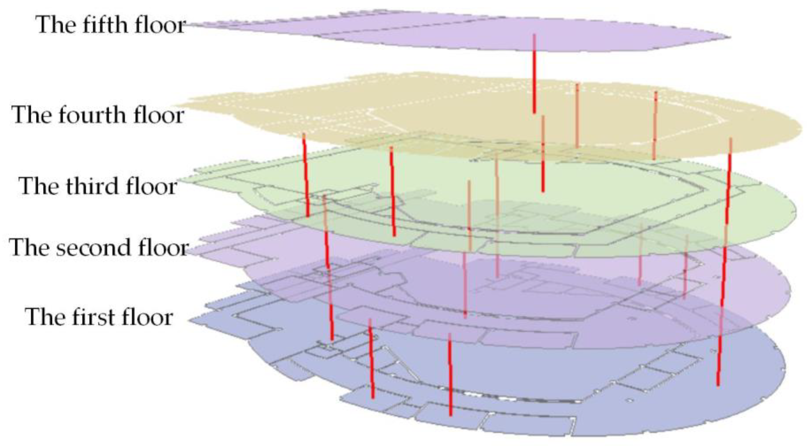
The red lines express the cross-floor space connectivity between single-floor spaces, as shown in Figure 19. This indicates that the hole is extracted in the up-floor slab and used to judge the up-and-down connectivity relationship between adjacent single-floor indoor spaces. The results show that a cross-floor space exists in each pair of building floors.
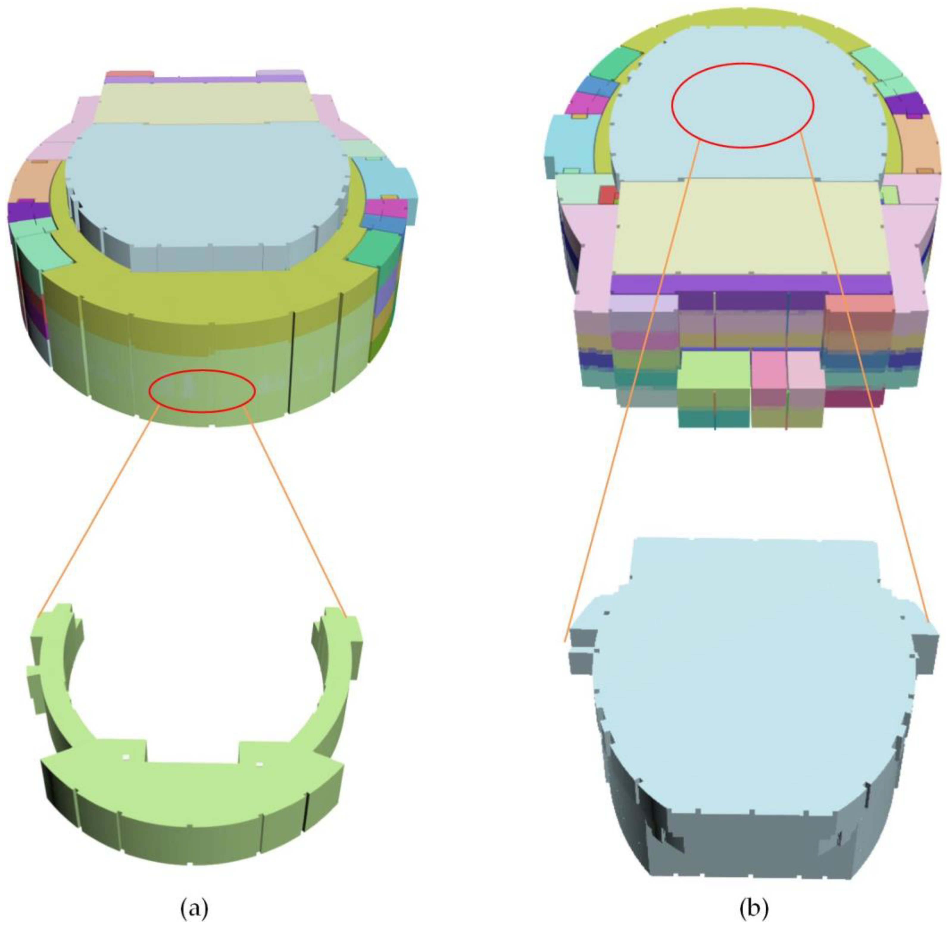
In Figure 20, the 3D indoor spaces are distinguished by different colors. The rendered results show that the extracted geometric information of the indoor spaces completely covers the entire building, including the rooms on each floor and the cross-floor spaces. In particular, two cross-floor spaces are highlighted individually. Figure 20a,b show the entrance hall and audience hall, respectively. Table 4 indicates that there are 25 cross-floor indoor spaces in the building. The modeling results show that the complex indoor cross-floor space is extracted correctly using the single-floor spaces and connectivity relationship.
5. Discussion
5.1. Accuracy of the Method
Figure 21 shows the isolated components in the plan. Figure 21a displays the first-floor plan of the concert hall building. The partially enlarged plan views show the complicated situations with isolated boundary components in the building interior. For example, Figure 21b shows an indoor space containing an isolated column, and Figure 21c shows an indoor space containing a separate wall.
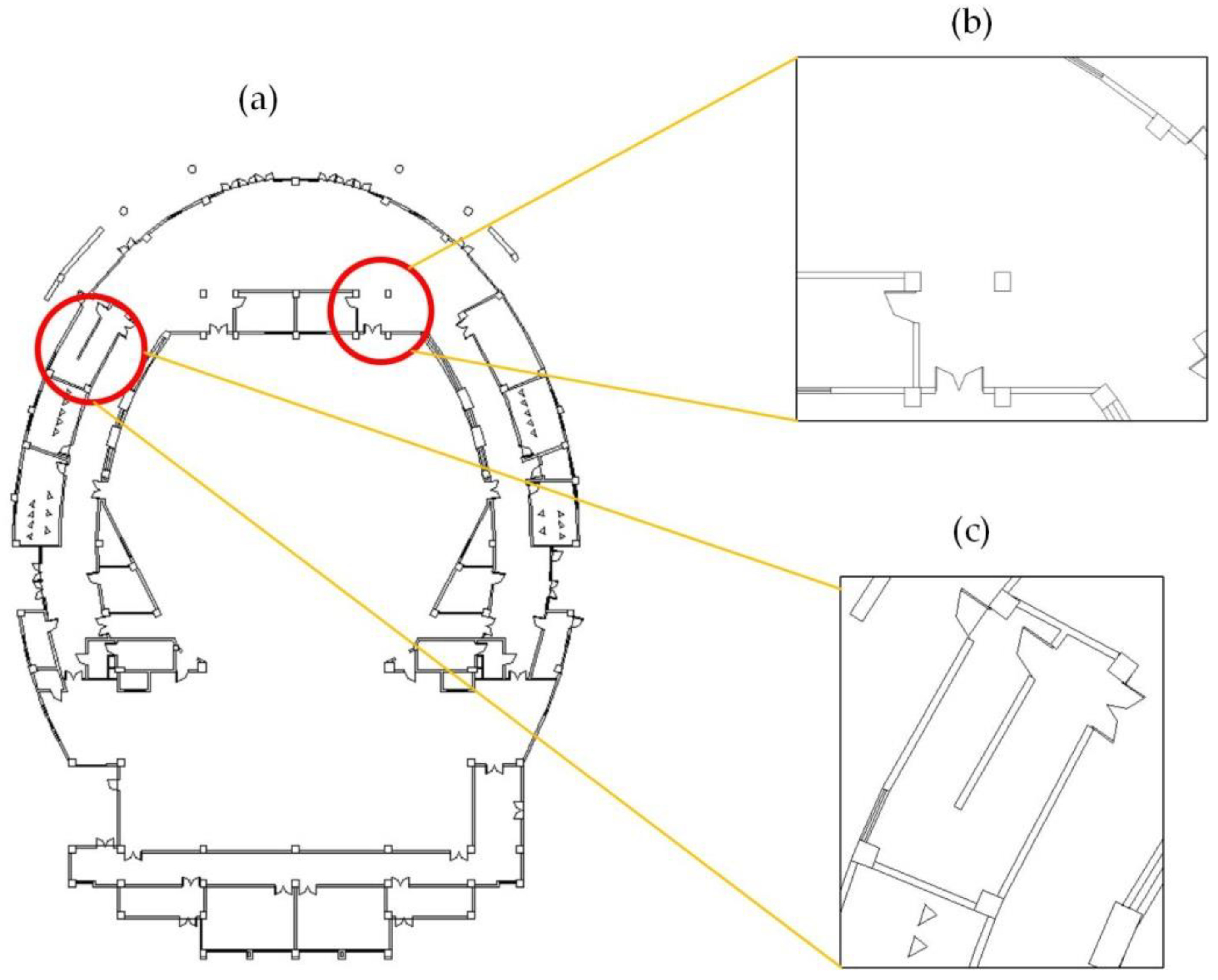
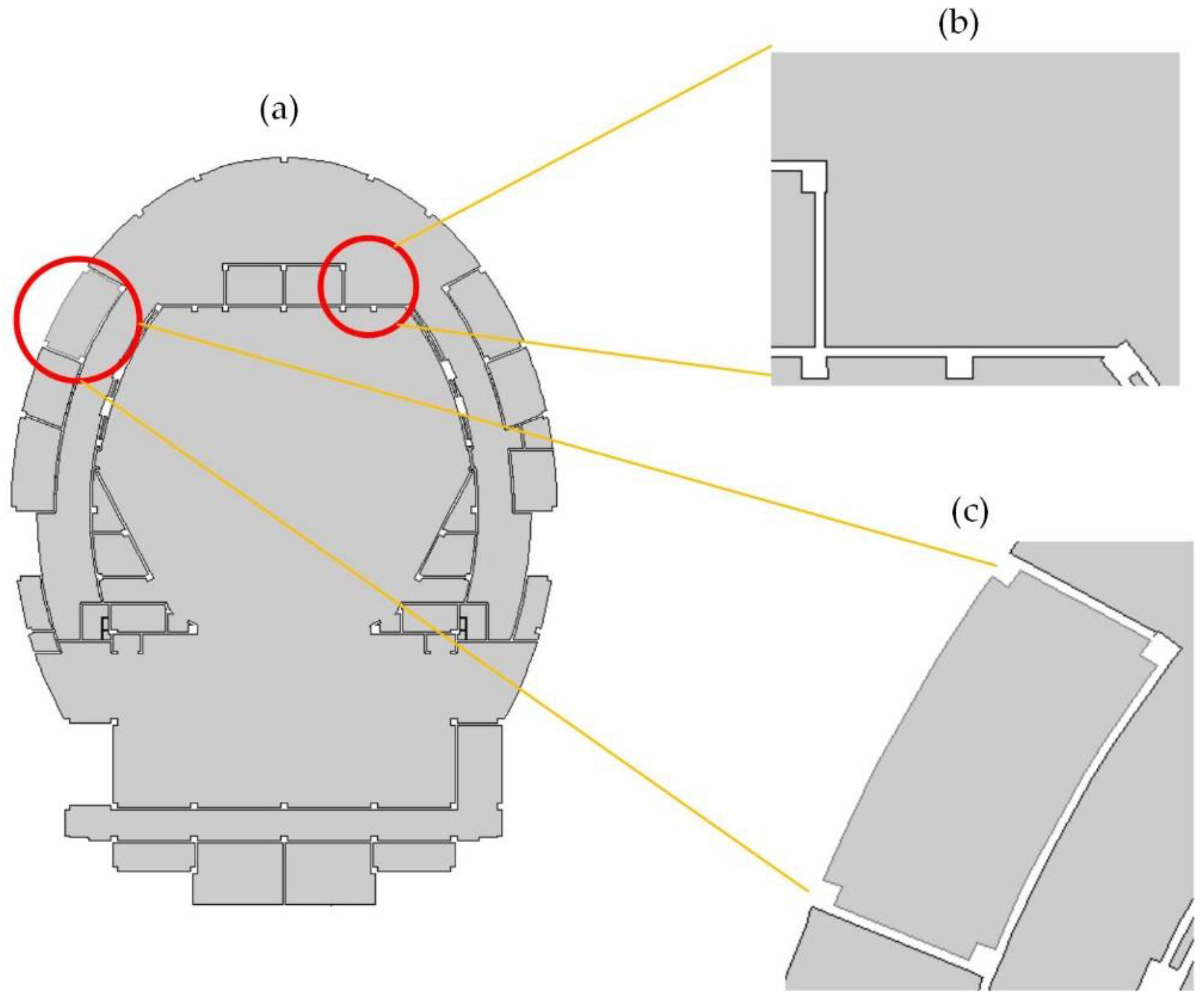
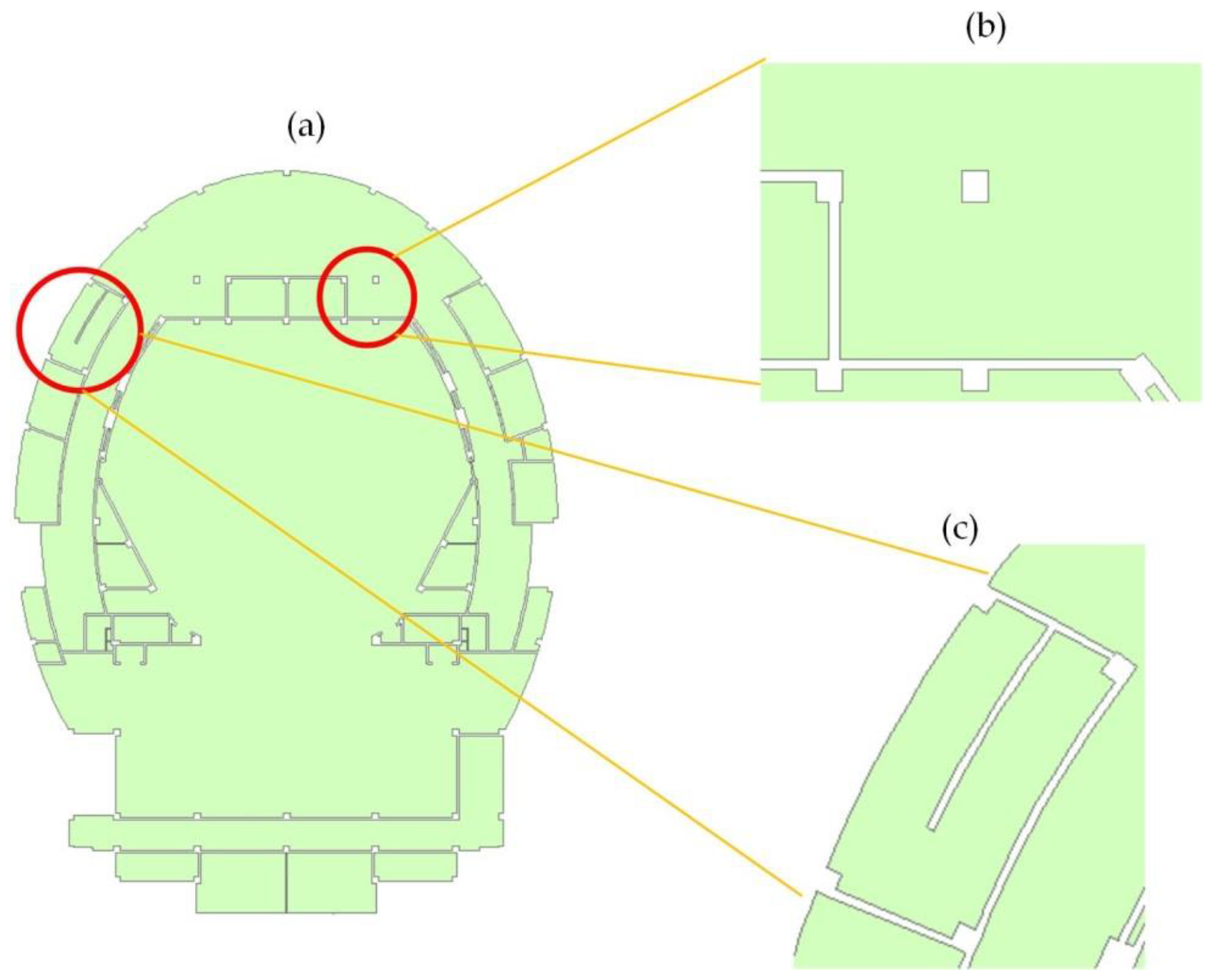
Figure 22 show the extraction results obtained for the indoor spaces using the search-loop method. Figure 22a displays all indoor spaces extracted from the first-floor plan. Figure 22b shows that the geometry of the indoor space contains the region occupied by the isolated column. Figure 22c shows that the region occupied by the separated wall is not displayed in the geometry of the indoor space. Figure 23a shows the results extracted for the first floor using the proposed method. Figure 23b,c show that the indoor spaces contain the interior boundary that represents the regions occupied by the isolated column and separated wall.
Compared with the search-loop method, the indoor space extraction method uses the Boolean difference operation to subtract the space occupied by interior components such as the isolated columns and walls of the interior space. Interior islands are formed in the geometry of the indoor space entity; hence, a more accurate geometry of the indoor space is obtained. At the same time, the accurate semantic of the indoor space is extracted through cross-floor indoor space modeling.
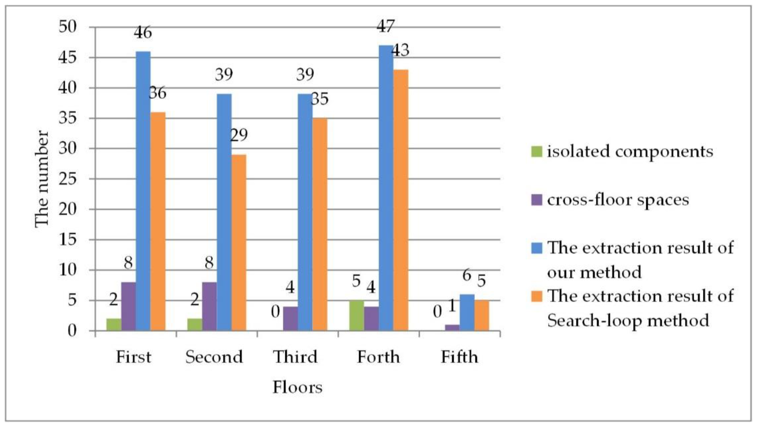
As presented in Figure 24, the number of correct indoor spaces obtained using our method is higher than that obtained through the search-loop method. This proves that the proposed method is suitable for the extraction of indoor spaces in complex environments. The accuracy of the proposed method becomes more evident with the increase in complex situations. For example, the large difference of two methods in the number of correct indoor spaces is 10 on the first and second floors, because there are greater complicated situations on these two floors. The search-loop method cannot obtain correct geometry of the complex situations that contain isolated components and cross-floor spaces.
5.2. Advantages of the Method
The proposed novel extract indoor space method, which considers the complex indoor space environments, has important significance for BIM and GIS integration research.
First, the indoor space extraction method solves two complex situation modeling problems (Table 5), i.e., isolated components and cross-floor space, in indoor environments. These situations are becoming increasingly common in large public indoor scenes, such as theaters/shopping centers. The more accurate results of the proposed indoor space extraction method can serve as the foundation for the advent of smart cities.
Second, the process of the indoor space extraction is almost fully automatic. Most existing BIM software is based on an artificial extraction of a single space. In this study, we provide a procedure to automatically extract indoor spaces through 3D BIM.
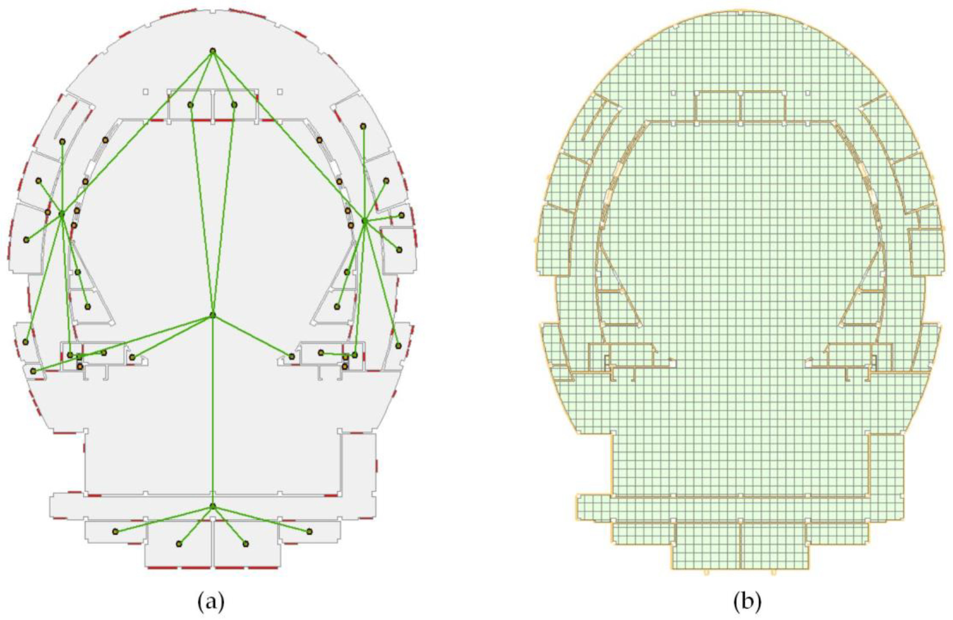
Finally, a network model can be converted based on the indoor space entity model with boundary relationships. The boundary relationships of indoor spaces were reconstructed in this study. The connectivity between two adjacent spaces can be determined as long as there are openings, such as doors, in indoor space boundary components. As shown in Figure 25a, the indoor space entities extracted from the first floor are used to construct a network model for the indoor space. In addition, a grid model is built by geometrical regular subdivision of the indoor space entities, as shown in Figure 25b.
6. Conclusions
This paper proposed a method for extracting architectural indoor spaces, including single-floor and cross-floor spaces. The modeling and boundary relationship reconstruction of single-floor indoor spaces can be realized under complex indoor conditions. The connectivity between single-floor building spaces is determined to model indoor cross-floor spaces. The extraction results of specific case studies show that isolated boundary components play an important role in limiting indoor spaces and that the proposed method can deal with complicated situations.
Isolated boundary components and cross-floor spaces should be considered when extracting indoor spaces to obtain more accurate geometry. The proposed method for rebuilding boundary relationships is highly applicable for improving the efficiency of model transformation. The proposed approach can accurately and automatically reconstruct the indoor spaces of a building. The extracted indoor spaces provide necessary support for indoor navigation, environmental simulations, information management, and other application analyses.
However, this study focused only on the extraction of indoor spaces. Future works will explore the integrated modeling of indoor and outdoor spaces and dynamic indoor simulations, such as fire and indoor airflow motion.
Author Contributions
Y.P. proposed the original idea, set up the case study, performed most of the method, and wrote the draft of the manuscript. C.Z., G.L., B.L., and L.Z. principally conceived the idea and provided financial support.
Funding
This study was supported by the National Natural Science Foundation of China (No. 41571381), National Natural Science Foundation of China (No. 41501422), and the National Key Research and Development Program of China (No. 2017YFB0503503).
Conflicts of Interest
The authors declare no conflicts of interest.
References
- Goodchild, M.F. Virtual geographic environments as collective constructions. Acta Geod. Cartogr. Sin. 2008, 31, 1–6. [Google Scholar]
- Diakité, A.A.; Zlatanova, S. Spatial subdivision of complex indoor environments for 3D indoor navigation. Int. J. Geogr. Inf. Sci. 2017, 32, 213–235. [Google Scholar] [CrossRef] [Green Version]
- Worboys, M. Modeling indoor space. In Proceedings of the 3rd ACM SIGSPATIAL International Workshop on Indoor Spatial Awareness, Chicago, IL, USA, 1 November 2011; pp. 1–6. [Google Scholar]
- Li, X.; Claramunt, C.; Ray, C. A grid graph-based model for the analysis of 2D indoor spaces. Comput. Environ. Urban Syst. 2010, 34, 532–540. [Google Scholar] [CrossRef]
- Zlatanova, S.; Liu, L.; Sithole, G.; Zhao, J.; Mortari, F. Space Subdivision for Indoor Applications; Delft University of Technology, OTB Research Institute for the Built Environment: Delft, The Netherlands, 31 December 2014. [Google Scholar]
- Zlatanova, S.; Liu, L.; Sithole, G. A conceptual framework of space subdivision for indoor navigation. In Proceedings of the 5th ACM Sigspatial International Workshop on Indoor Spatial Awareness, Orlando, FL, USA, 5–8 November 2013; pp. 37–41. [Google Scholar]
- Li, D.; Zhu, Q.; Liu, Q.; Xu, P. From 2D to 3D GIS for cybercity. Geo-Spat. Inf. Sci. 2004, 7, 1–5. [Google Scholar]
- Xiong, Q.; Zhu, Q.; Du, Z.; Zlatanova, S.; Zhang, Y.; Zhou, Y.; Li, Y. Free multi-floor indoor space extraction from complex 3D building models. Earth Sci. Inf. 2017, 10, 69–83. [Google Scholar] [CrossRef]
- Lee, J. A spatial access-oriented implementation of a 3-D GIS topological data model for urban entities. GeoInformatica 2004, 8, 237–264. [Google Scholar] [CrossRef]
- Gilliéron, P.Y.; Büchel, D.; Spassov, I.; Merminod, B. Indoor navigation performance analysis. In Proceedings of the 8th European Navigation Conference GNSS, Rotterdam, The Netherlands, 17–19 May 2004. [Google Scholar]
- Choi, J.; Lee, J. 3D geo-network for agent-based building evacuation simulation. In 3D Geo-Information Sciences; Lee, J., Zlatanova, S., Eds.; Springer: Berlin/Heidelberg, Germany, 2009; pp. 283–299. [Google Scholar]
- Choset, H.; Lynch, K.; Hutchinson, S.; Kantor, G.; Burgard, W.; Kavraki, L.; Thrun, S. Principles of Robot Motion: Theory, Algorithms, and Implementations; MIT Press: Cambridge, MA, USA, 2005; p. 512. [Google Scholar]
- Kneidl, A.; Borrmann, A.; Hartmann, D. Generation and use of sparse navigation graphs for microscopic pedestrian simulation models. Adv. Eng. Inf. 2012, 26, 669–680. [Google Scholar] [CrossRef]
- Lorenz, B.; Ohlbach, H.J.; Stoffel, E.P. A hybrid spatial model for representing indoor environments. Lect. Notes Comput. Sci. 2006, 4295, 102–112. [Google Scholar]
- Wallgrün, J.O. Autonomous construction of hierarchical voronoi-based route graph representations. In Proceedings of the Spatial Cognition IV: Reasoning, Action, Interaction, Frauenchiemsee, Germany, 11–13 October 2005; pp. 413–433. [Google Scholar]
- Geraerts, R. Planning short paths with clearance using explicit corridors. In Proceedings of the IEEE International Conference on Robotics and Automation, Anchorage, AK, USA, 3–7 May 2010; pp. 1997–2004. [Google Scholar]
- Krūminaitė, M.; Zlatanova, S. Indoor space subdivision for indoor navigation. In Proceedings of the Sixth ACM SIGSPATIAL International Workshop on Indoor Spatial Awareness, Dallas/Fort Worth, TX, USA, 4 November 2014; pp. 25–31. [Google Scholar]
- Li, Y.; He, Z. 3D indoor navigation: A framework of combining BIM with 3D GIS. In Proceedings of the 44th World Congress of the International Society of City and Regional Planners (ISOCARP), Dalian, China, 19–23 September 2008. [Google Scholar]
- Tang, S.J.; Zhu, Q.; Wang, W.W.; Zhang, Y.T. Automatic topology derivation from IFC building model for in-door intelligent navigation. ISPRS—Int. Arch. Photogr. Remote Sens. Spat. Inf. Sci. 2015, XL-4/W5, 7–11. [Google Scholar] [CrossRef]
- Lin, Y.H.; Liu, Y.S.; Gao, G.; Han, X.G.; Lai, C.Y.; Gu, M. The IFC-based path planning for 3D indoor spaces. Adv. Eng. Inf. 2013, 27, 189–205. [Google Scholar] [CrossRef]
- Isikdag, U.; Zlatanova, S.; Underwood, J. A bim-oriented model for supporting indoor navigation requirements. Comput. Environ. Urban Syst. 2013, 41, 112–123. [Google Scholar] [CrossRef]
- Lamarche, F.; Donikian, S. Crowd of virtual humans: A new approach for real time navigation in complex and structured environments. Comput. Graph. Forum 2010, 23, 509–518. [Google Scholar] [CrossRef] [Green Version]
- Stoffel, E.P.; Lorenz, B.; Ohlbach, H.J. Towards a semantic spatial model for pedestrian indoor navigation. In Proceedings of the 2007 Conference on Advances in Conceptual Modeling: Foundations and Applications, Auckland, New Zealand, 5–9 November 2007; pp. 328–337. [Google Scholar]
- Liu, L.; Zlatanova, S. A “door-to-door” path-finding approach for indoor navigation. In Proceedings of the Gi4DM 2011: GeoInformation for Disaster Management, Antalya, Turkey, 3–8 May 2011. [Google Scholar]
- Gabriel, G.; Stéphane, C.; Sisi, Z.; Yannick, B.; Johanne, S.P.; Peter, V.O. Indoor pedestrian navigation using foot-mounted imu and portable ultrasound range sensors. Sensors 2011, 11, 7606–7624. [Google Scholar] [CrossRef]
- Afyouni, I.; Ray, C.; Claramunt, C. Spatial models for context-aware indoor navigation systems: A survey. J. Spat. Inf. Sci. 2012, 2012, 85–123. [Google Scholar] [CrossRef]
- Liu, X.; Xie, N.; Tang, K.; Jia, J. Lightweighting for Web3D visualization of large-scale BIM scenes in real-time. Graph. Models 2016, 88, 40–56. [Google Scholar] [CrossRef]
- Goldstein, R.; Breslav, S.; Khan, A. Towards voxel-based algorithms for building performance simulation. In Proceedings of the IBPSA—Canada eSim Conference, Ottawa, ON, Canada, 7–10 May 2014. [Google Scholar]
- Bandi, S.; Thalmann, D. Space discretization for efficient human navigation. Comput. Graph. Forum 1998, 17, 195–206. [Google Scholar] [CrossRef]
- Lewis, R.; Séquin, C. Generation of 3D building models from 2D architectural plans. Comput.-Aided Des. 1998, 30, 765–779. [Google Scholar] [CrossRef]
- Zhu, J.; Zhang, H.; Wen, Y. A new reconstruction method for 3D buildings from 2D vector floor plan. Comput.-Aided Des. Appl. 2014, 11, 704–714. [Google Scholar] [CrossRef]
- Ah-Soon, C.; Tombre, K. Variations on the analysis of architectural drawings. In Proceedings of the Fourth International Conference on Document Analysis and Recognition, Ulm, Germany, 18–20 August 1997; pp. 347–351. [Google Scholar]
- Zhi, G.; Lo, S.; Fang, Z. A graph-based algorithm for extracting units and loops from architectural floor plans for a building evacuation model. Comput.-Aided Des. 2003, 35, 1–14. [Google Scholar] [CrossRef]
- Autodesk Revit Help: About Defining the Upper Boundary of a Room. 2017. Available online: http://help.autodesk.com/view/RVT/2017/ENU/?guid=GUID-C3040C34-62FC-4F31-9594-1082CFF86FFE (accessed on 26 May 2018).
- Tsiliakou, E.; Dimopoulou, E. 3D network analysis for indoor space applications. ISPRS—Int. Arch. Photogr. Remote Sens. Spat. Inf. Sci. 2016, XLII-2/W2, 147–154. [Google Scholar] [CrossRef]
- Tang, P.; Huber, D.; Akinci, B.; Lipman, R.; Lytle, A. Automatic reconstruction of as-built building information models from laser-scanned point clouds: A review of related techniques. Autom. Constr. 2010, 19, 829–843. [Google Scholar] [CrossRef]
- Becker, S.; Peter, M.; Fritsch, D. Grammar-supported 3D indoor reconstruction from point clouds for as-built BIM. ISPRS Ann. Photogr. Remote Sens. Spat. Inf. Sci. 2015, II-3/W4, 17–24. [Google Scholar] [CrossRef]
Figure 1.
Complexity of large buildings. (a) Actual view and (b) plan of isolated components. (c) Indoor space results extracted using the search-loop method. S1 is the indoor space polygon obtained by the search-loop method. S2–S6 are the regions occupied by the isolated components of the building; (d) Actual results. I1–I5 are the internal islands of S1′.

Figure 2.
Overview of the proposed indoor space extraction procedure: (a) Building components; (b) calculation of the indoor space boundary of a single floor; (c) indoor single-floor space extraction of a building; (d) identification of the downward connectivity of single-floor space; (e) indoor cross-floor space extracting of a building; and (f) extraction result, (a–c) are part of the building in (d) for clear expression.

Figure 3.
Boundary components: (a) walls and (b) columns.

Figure 4.
Calculation of the indoor space boundary: (a) boundary components of spaces and (b) results of the Boolean operation.
Figure 4.
Calculation of the indoor space boundary: (a) boundary components of spaces and (b) results of the Boolean operation.

Figure 5.
Flowchart for extracting a single-floor space.

Figure 6.
Extraction and modeling of single-floor building spaces in floor plan view: (a) convex hull of ; (b) result of the Boolean difference operation; (c) distinction between indoor and outdoor spaces, and (d) resulting indoor single-floor spaces.
Figure 6.
Extraction and modeling of single-floor building spaces in floor plan view: (a) convex hull of ; (b) result of the Boolean difference operation; (c) distinction between indoor and outdoor spaces, and (d) resulting indoor single-floor spaces.

Figure 7.
Construction of the boundary relationship.

Figure 8.
Examples of cross-floor spaces: (a) pipe well, (b) elevator shaft, (c) air duct well, and (d) atrium.
Figure 8.
Examples of cross-floor spaces: (a) pipe well, (b) elevator shaft, (c) air duct well, and (d) atrium.

Figure 9.
Cross-floor space representation in a construction plan: (a) pipe well and (b) atrium.

Figure 10.
Polyline of the hole symbol: (a) discrete line segments and (b) topological reconstruction.
Figure 10.
Polyline of the hole symbol: (a) discrete line segments and (b) topological reconstruction.

Figure 11.
Judging the connectivity of building spaces: (a) cross-floor space and (b) single-floor space.
Figure 11.
Judging the connectivity of building spaces: (a) cross-floor space and (b) single-floor space.

Figure 12.
Space area relationships between the upper and lower floors: (a) , (b) , and (c) . is the upper indoor space area, and is the lower space area.
Figure 12.
Space area relationships between the upper and lower floors: (a) , (b) , and (c) . is the upper indoor space area, and is the lower space area.

Figure 13.
Flowchart for extracting a cross-floor space.

Figure 14.
Comparison of single-floor and cross-floor space extraction: (a) single-floor space 3D model, (b) floor slab without a hole, (c) cross-floor space 3D model, and (d) floor slab with a hole.
Figure 14.
Comparison of single-floor and cross-floor space extraction: (a) single-floor space 3D model, (b) floor slab without a hole, (c) cross-floor space 3D model, and (d) floor slab with a hole.

Figure 15.
The indoor space automatic extraction system: (a) BIM data integrated within GIS software and (b) indoor space automatic extraction.
Figure 15.
The indoor space automatic extraction system: (a) BIM data integrated within GIS software and (b) indoor space automatic extraction.

Figure 16.
Floor plans of the building: (a) first floor, (b) second floor, (c) third floor, (d) fourth floor, and (e) fifth floor.
Figure 16.
Floor plans of the building: (a) first floor, (b) second floor, (c) third floor, (d) fourth floor, and (e) fifth floor.

Figure 17.
Single-floor space extraction results of the building: (a) first floor, (b) second floor, (c) third floor, (d) fourth floor, and (e) fifth floor.
Figure 17.
Single-floor space extraction results of the building: (a) first floor, (b) second floor, (c) third floor, (d) fourth floor, and (e) fifth floor.

Figure 18.
Boundary relationship.

Figure 19.
Connectivity relationships of indoor cross-floor spaces.

Figure 20.
Results of the indoor cross-floor space modeling: (a) hallway and (b) audience hall.

Figure 21.
Situation of isolated components: (a) first floor plan, (b) isolated column, and (c) isolated wall.
Figure 21.
Situation of isolated components: (a) first floor plan, (b) isolated column, and (c) isolated wall.

Figure 22.
Extraction results obtained using the search-loop method: (a) first floor plan, (b) isolated column, and (c) isolated wall.
Figure 22.
Extraction results obtained using the search-loop method: (a) first floor plan, (b) isolated column, and (c) isolated wall.

Figure 23.
Extraction results obtained using proposed method: (a) first floor plan, (b) isolated column, and (c) isolated wall.
Figure 23.
Extraction results obtained using proposed method: (a) first floor plan, (b) isolated column, and (c) isolated wall.

Figure 24.
Comparison of the number of correct indoor spaces.

Figure 25.
Conversion to other indoor space expression models: (a) network and (b) grid model.


Table 1.
Building components.
| Name | Semantic Description |
|---|---|
| Wall | Main component in the vertical direction. It plays load-bearing, enclosure, and space separation roles and is the main expression of the boundary for a building space in the vertical direction. |
| Curtain wall | Consists of a metal frame and a plate and does not bear the load of the main structure. |
| Column | Mainly supports the vertical load of the building. |
| Railing | Height between the human chest and abdomen; used to ensure personal safety or separate a space. |
| Floor slab | Platform that directly bears loads and divides a space in the horizontal direction of the building. |
Table 2.
Number of boundary components.
| Floor | Wall | Column | Railing | Total Number of Boundary Components |
|---|---|---|---|---|
| First floor | 240 | 85 | 6 | 331 |
| Second floor | 215 | 84 | 6 | 305 |
| Third floor | 218 | 81 | 4 | 303 |
| Fourth floor | 260 | 76 | 4 | 340 |
| Fifth floor | 90 | 38 | 0 | 128 |
Table 3.
Number of single-floor indoor spaces in the experimental data.
| Floor | Number of Single-Floor Indoor Spaces |
|---|---|
| First floor | 46 |
| Second floor | 39 |
| Third floor | 39 |
| Fourth floor | 47 |
| Fifth floor | 6 |
Table 4.
Number of cross-floor indoor spaces in the experimental data.
| Floor | Number of Cross-Floor Indoor Spaces |
|---|---|
| First floor | 8 |
| Second floor | 8 |
| Third floor | 4 |
| Fourth floor | 4 |
| Fifth floor | 1 |
Table 5.
Comparison of the extraction methods.
| Indoor Space Situation | Search-Loop Method | Our Method | |
|---|---|---|---|
| Single-floor space | Without isolated component | √ | √ |
| With isolated component | × | √ | |
| Cross-floor space | × | √ | |
© 2018 by the authors. Licensee MDPI, Basel, Switzerland. This article is an open access article distributed under the terms and conditions of the Creative Commons Attribution (CC BY) license (http://creativecommons.org/licenses/by/4.0/).
Share and Cite
MDPI and ACS Style
Pang, Y.; Zhang, C.; Zhou, L.; Lin, B.; Lv, G. Extracting Indoor Space Information in Complex Building Environments. ISPRS Int. J. Geo-Inf. 2018, 7, 321. https://0-doi-org.brum.beds.ac.uk/10.3390/ijgi7080321
AMA Style
Pang Y, Zhang C, Zhou L, Lin B, Lv G. Extracting Indoor Space Information in Complex Building Environments. ISPRS International Journal of Geo-Information. 2018; 7(8):321. https://0-doi-org.brum.beds.ac.uk/10.3390/ijgi7080321
Chicago/Turabian StylePang, Yueyong, Chi Zhang, Liangchen Zhou, Bingxian Lin, and Guonian Lv. 2018. "Extracting Indoor Space Information in Complex Building Environments" ISPRS International Journal of Geo-Information 7, no. 8: 321. https://0-doi-org.brum.beds.ac.uk/10.3390/ijgi7080321
Note that from the first issue of 2016, this journal uses article numbers instead of page numbers. See further details here.