Integrated UAV-Based Real-Time Mapping for Security Applications


German Aerospace Center (DLR), Rutherfordstr. 2, 12489 Berlin, Germany
*
Author to whom correspondence should be addressed.
†
These authors contributed equally to this work.
ISPRS Int. J. Geo-Inf. 2019, 8(5), 219; https://0-doi-org.brum.beds.ac.uk/10.3390/ijgi8050219
Submission received: 17 February 2019
/
Revised: 23 April 2019
/
Accepted: 2 May 2019
/
Published: 8 May 2019
(This article belongs to the Special Issue Innovative Sensing - From Sensors to Methods and Applications)
Abstract
:Security applications such as management of natural disasters and man-made incidents crucially depend on the rapid availability of a situation picture of the affected area. UAV-based remote sensing systems may constitute an essential tool for capturing aerial imagery in such scenarios. While several commercial UAV solutions already provide acquisition of high quality photos or real-time video transmission via radio link, generating instant high-resolution aerial maps is still an open challenge. For this purpose, the article presents a real-time processing tool chain, enabling generation of interactive aerial maps during flight. Key element of this tool chain is the combination of the Terrain Aware Image Clipping (TAC) algorithm and 12-bit JPEG compression. As a result, the data size of a common scenery can be reduced to approximately 0.4% of the original size, while preserving full geometric and radiometric resolution. Particular attention was paid to minimize computational costs to reduce hardware requirements. The full workflow was demonstrated using the DLR Modular Airborne Camera System (MACS) operated on a conventional aircraft. In combination with a commercial radio link, the latency between image acquisition and visualization in the ground station was about 2 s. In addition, the integration of a miniaturized version of the camera system into a small fixed-wing UAV is presented. It is shown that the described workflow is efficient enough to instantly generate image maps even on small UAV hardware. Using a radio link, these maps can be broadcasted to on-site operation centers and are immediately available to the end-users.
1. Introduction
Relief coordination in the case of major disasters is a complex task. Effective decisions require reliable and up-to-date information [1]. Especially in the first phase of emergency response, immediately available high-resolution aerial maps are of great value for tactical decision-making [2]. With such maps, users such as first responder assessment teams or fire fighters are able to locate areas of interest, perform measurements, evaluate the situation and analyze temporal changes. Since time is vital in such situations, satellite images or appropriately equipped survey aircraft are often too slow. Novel UAV-based reconnaissance systems are therefore increasingly used for decision-relevant information acquisition [3,4,5,6]. One of the main advantages of UAV-based imagery is their actual availability, as such systems can be used as an operational asset of the rescue or assessment teams. This allows teams to decide when, where, and how affected areas are captured, depending on the current field situation.
Common commercial UAV solutions allow for capturing aerial images or videos, and provide a direct video stream transmission to a remote operator, e.g., MikroKopter, AscTec Falcon8, SenseFly eBee, Trimble UX5, Quantum Trinity/Tron, Wingcopter, ALTI Transition, DJI Phantom and DJI Inspire. This makes them a beneficial tool for assessing close vicinity from bird’s-eye view [7,8].
While still images or video streaming is available in real-time, generating aerial maps of captured areas has to be done in a post-processing step after landing. Several software tools enable map or even 3D point cloud generation out of (more or less arbitrary) aerial imagery (e.g., Agisoft Photoscan, Pix4D, and Capturing Reality). Generally speaking, two different approaches exist: stitching methods that work solely in the texture domain and photogrammetric methods that work in the spatial domain exploiting the imaging geometry [9,10]. Both approaches usually use some kind of image correlation, resulting for example in a set of matched tie points. While the former methods use these points for stitching procedures [11,12], the latter use them for bundle adjustment followed by stereo-photogrammetric methods or structure from motion (SFM) approaches [13,14,15,16,17]. However, due to extensive image analysis and matching procedures within both approaches, these processes are time consuming and resource intensive. Depending on the number of recorded images to be processed, the spatial resolution and the extent of the captured area, generating aerial maps may easily take up to several hours. However, security and rescue applications usually require a situation picture as quickly as possible.
To fill this gap, a real-time image processing tool chain is presented in this article. It enables the automated and immediate generation of high-resolution interactive maps already during flight. The workflow has already been demonstrated on a MACS aerial camera system [18]. In a joint effort of German Aerospace Center (DLR) and the first response organization International Search and Rescue Germany (I.S.A.R.), a miniaturized version of MACS is currently being developed to enable real-time mapping even on small UAVs (see Figure 11) [19,20,21]. The current state of this development is explained below.
2. Materials and Methods
In the following. the real-time processing chain is outlined. Particular stages, their challenges and a proposed solution are presented in more detail. Actually, the presented processing chain may serve as a template. Depending on the application, the particular focus, and the operational conditions and constraints, each individual stage may be substituted by another suitable solution. Furthermore, the chain presented here does not include a distortion correction stage, which may be included depending on optical characteristics of applied cameras. However, the present solution has been successfully implemented and tested in a demonstrator UAV-based camera system, which is introduced in the last part of this section.
2.1. Prerequisites
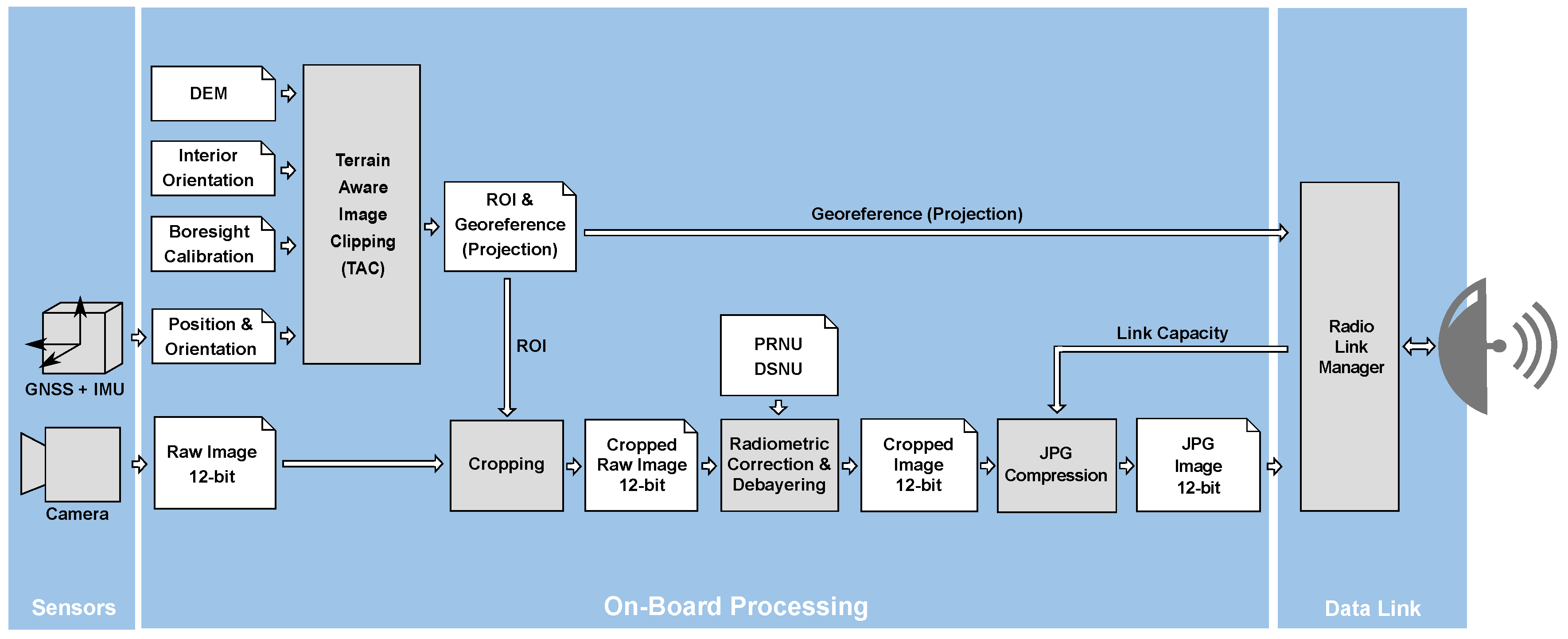
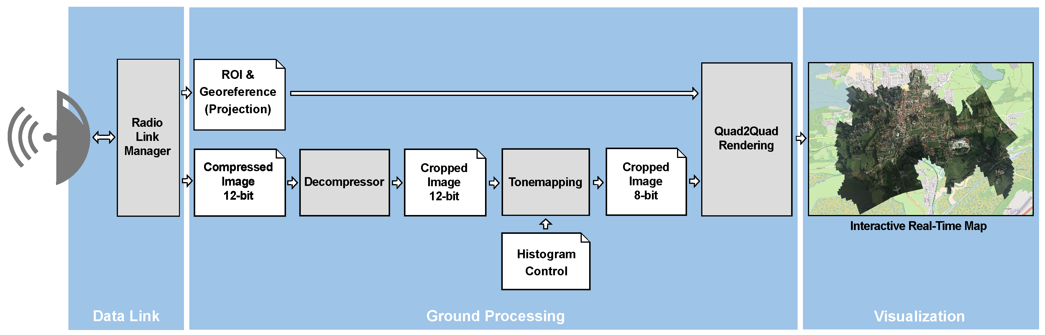
The necessary input sensor stage consists of one or more imaging sensors (in our case, matrix cameras) as well as a real-time capable position and attitude determination system, such as a global navigation satellite system (GNSS) in combination with an inertial measurement unit (IMU). All sensors must be synchronized in a way that, for each captured image, its camera position and orientation at the time of triggering is precisely determined. Figure 1 shows an overview of the on-board processor stages. Figure 2 shows remaining stages of the processing chain in the ground segment.
2.2. Terrain Aware Image Clipping (TAC)
Each captured aerial image represents a particular area on ground, called the footprint of that image. Extent and shape of this footprint are primarily determined by the camera’s interior orientation (particularly sensor size and focal length), the position and orientation of the camera at the time of exposure, and the terrain of the captured area. In the case of continuous triggering, the footprints of two consecutively captured images may overlap more or less depending on the recording frame rate, current flight speed, attitude and distance to the ground.
To reduce the amount of image data to be processed and transmitted, the Terrain Aware Image Clipping (TAC) algorithm is applied [22]. For every captured image, this algorithm determines the minimal rectangular region of interest (ROI) such that the overlapping areas between adjacent footprints are minimized while maintaining a seamless coverage of the captured area between the two clipped images. The calculation is based on a spatial intersection between camera rays (i.e., rays of its corresponding pinhole camera model in space) and an elevation model of the captured area. For all samples, applications and demonstrations referred to in this paper, the SRTM-90 dataset as elevation model was used [23]. It provides nearly global coverage (up to 60 degrees of latitude) and is available free of charge. Alternatively, any other (e.g., more precise) local or global elevation models may be used as well. In general, a more precise elevation model will increase projection accuracy, particularly in mountainous terrain. However, when using nadir aerial images, i.e., the angle of view is near the perpendicular axis, height errors will only have a moderate effect on the result.
Figure 3 illustrates the operation principle of the TAC algorithm. Blue areas correspond to view cones of the particular aerial camera(s) at its trigger positions. Applying TAC minimizes the overlap between adjacent view cones without creating gaps in the captured area on ground.
Another effect of applying TAC is the preference for nadir-looking image parts, which reduces visual obstructions caused by adverse perspectives. Furthermore, in the case of nadir-mounted cameras, the algorithm generally favors central image areas. This minimizes geometric discontinuities between adjacent images caused by radial distortion. Moreover, central image parts are generally less affected by vignetting effects, thus resulting in radiometrically more homogeneous mosaics. However, a radiometric correction should be applied and is discussed in the following section.
2.3. Radiometric Correction
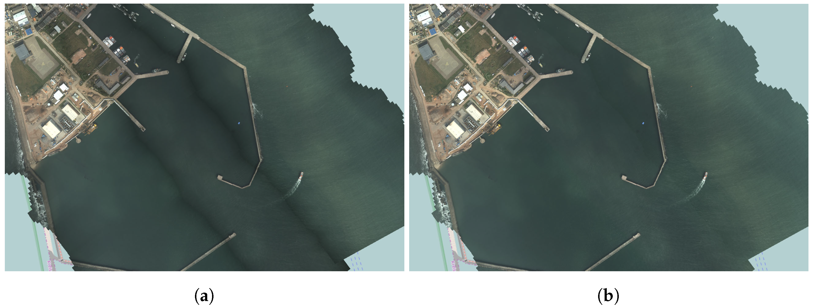
In general, raw imagery is affected by lens vignetting effects [24,25,26]. Without any correction, an aerial image mosaic may be radiometrically inhomogeneous. To produce a mosaic that is as homogeneous as possible, a radiometric correction is applied to each captured raw image. A comparison of generated aerial maps using uncorrected and radiometrically corrected images is shown in Figure 4. The correction is done by application of a flat-field correction (FFC), reverting two sensor-specific imaging effects: dark signal non-uniformity (DSNU) and photo response non-uniformity (PRNU) [27]. Depending on sensors characteristics and calibration procedure, this can be done either pixel-wise, or (as implemented in the demonstrator) by a polynomial fitted model.
2.4. Compression
A major challenge in the field of real-time aerial mapping is the amount of data to be transferred. In the approach presented here, primarily two techniques are used: First, redundant image data caused by overlapping image areas are minimized. This is achieved by application of TAC (see Section 2.2). Second, image compression is used to reduce transmitted image data. In recent decades, several image compression algorithms have been developed [28,29,30,31]. These algorithms have different features and properties, e.g., lossy vs. lossless compression methods, calculation expenses, supported number of channels and bit depths. Above all, two parameters are significant for real-time image transfer applications: performance in terms of throughput (how many images or how many pixels can be compressed per time) and compression ratio (ratio between size of raw and compressed image data).
When processing raw imagery, the maximum supported bit depth of the compression algorithm is an important issue. A compression algorithm that supports only a lower bit depth than the raw imagery would require a reduction in radiometric resolution. This is generally done by (linear or nonlinear) tone mapping, but may cause a significant loss of information in high contrast scenes. In these situations, support of the sensor’s original bit depth results in a data product retaining more information. Tone mapping should be done only in the last (visualization) stage by an operator, who can decide about important information in a specific scene.
A (lossy) compression algorithm supporting up to 12-bit depth is the libjpeg library provided by the Independent JPEG Group (IJG) [32]. It is available for different platforms, supports both gray-scale and (three-channel) full-color images and allows adjusting compression ratio by a quality setting of the encoder. Further advantages of libjpeg are that it is implemented very efficiently and thus comparatively fast and slim and allows for extremely small compressed image data.
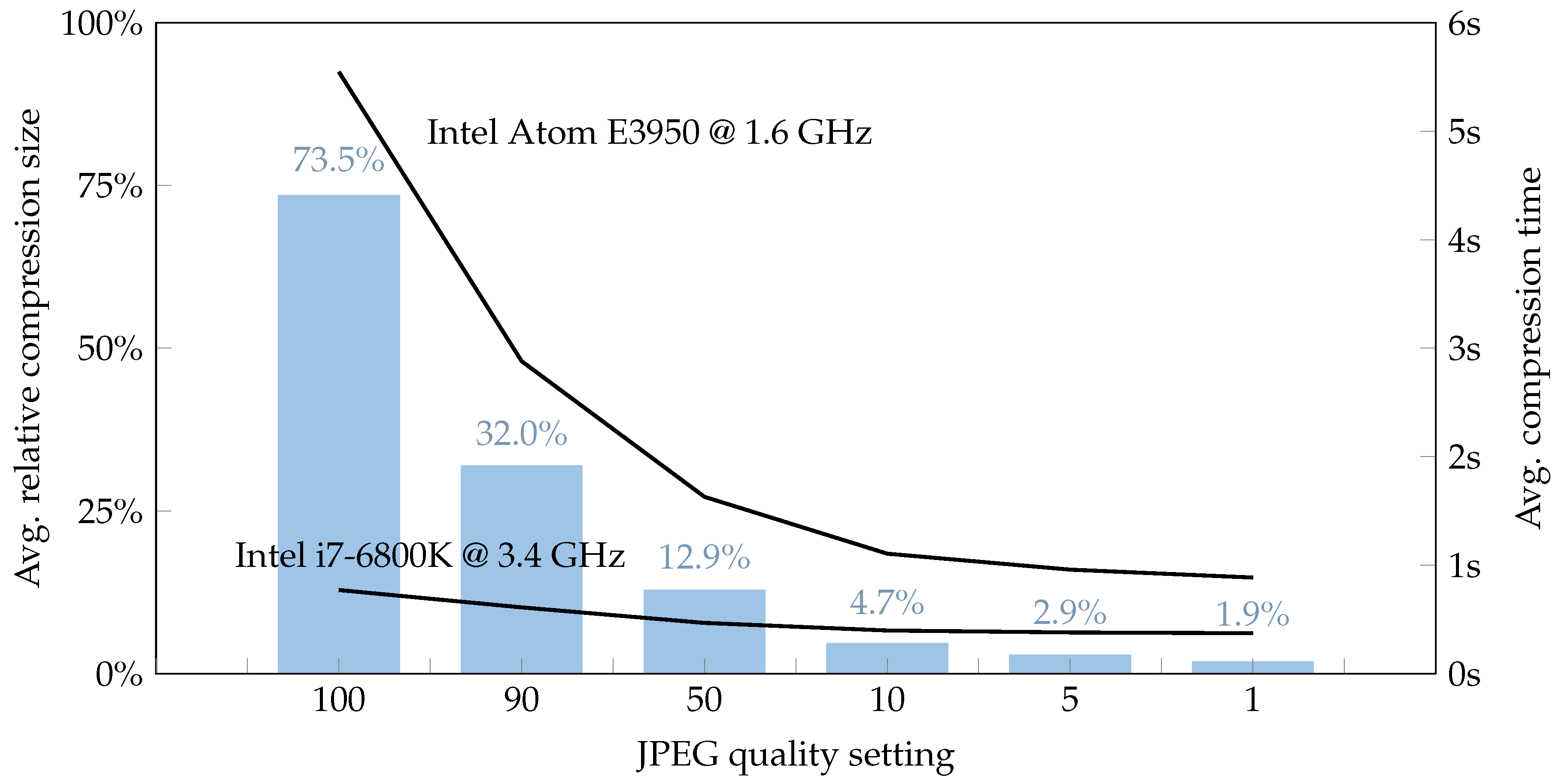
Figure 5 shows average JPEG compression performance results for different JPEG quality settings. Compression was applied to a sample aerial image dataset comprising 1185 single images, totally about 26 GB of raw image data. This dataset covers an area of about 5400 km with a variety of typical aerial scenes, ranging from water and coastal surfaces, rural and urban areas with buildings, roads and infrastructure. Aerial images were captured by 16 MPix camera modules with Bayer color-filter-array at an altitude of 350 m above ground level (AGL), resulting in a ground sampling distance (GSD) of ~5 cm per pixel. Raw images with a radiometric resolution of 12-bit were bilinearly debayered before compressing by libjpeg library in 3-channel color mode. Compression time was measured on two different systems, a standard workstation with an Intel i7-6800K desktop CPU and an embedded System with an Intel Atom E3950 CPU, as used in the MACS UAV demonstrator. Performance evaluation was executed single-threaded. Depending on the image content and JPEG quality setting, compression with low compression artifacts in the order of between 2% and 7% of raw image data size was observed.
A sample of a JPEG compressed aerial image is shown in Figure 6. The raw image was compressed by libjpeg version 9b in three-channel color mode, with radiometric depth of 12-bit and quality setting of 1 (highest compression). The upper row shows the original image, the lower row the result of JPEG compression. The compressed image has a size of 1.2 MB, which is about 5.3% of the raw image size. The raw aerial image was devignetted and bilinearly debayered before compressing. Despite its considerable compression ratio of about 20:1, the detail view exposes only few minimal compression artifacts.
2.5. Data Reduction by JPEG Compression and TAC
Depending on sensor resolution and trigger rate, the raw data stream may quickly exceed any available downlink bandwidth. The proposed approach proposes two techniques to significantly reduce this data stream: First, a geometric clipping is performed by application of TAC (see Section 2.2). Second, the remaining image data is compressed by JPEG compression algorithm (see Section 2.4).
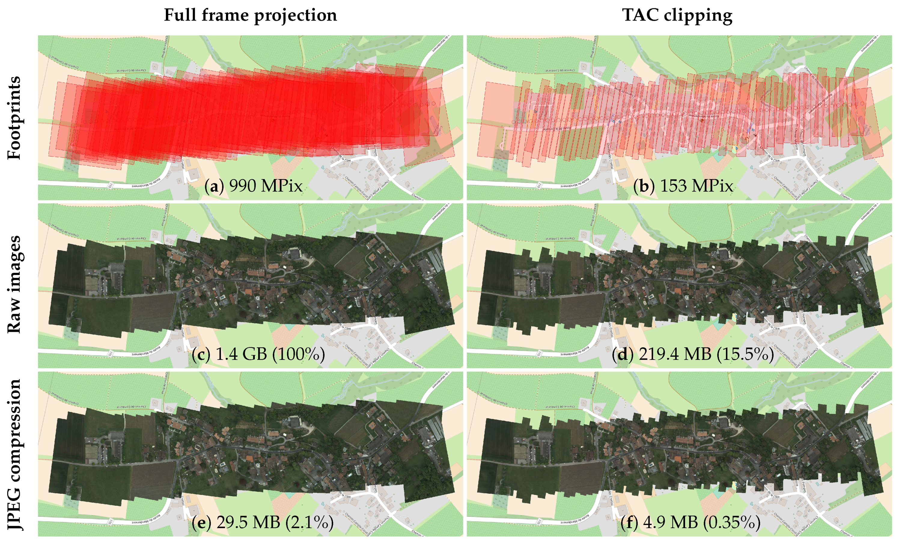
Figure 7 shows the data reduction performance of both techniques, using a sample scene of 63 consecutively recorded aerial images. The imagery was acquired with a MACS UAV camera system, carried by a fixed-wing UAV. The impact of the data reduction of both techniques was analyzed. In this scene, by application of TAC, the amount of pixels to be used for mosaicing was reduced by about 85% (ratio ~6:1). By application of JPEG compression on raw imagery (without any clipping), the size was reduced by about (ratio ~48:1). By combination of both techniques, the image data were reduced to 0.35% (ratio ~288:1). In this sample, the raw sensor data correspond to a data stream of about 180 Mbit/s. By application of both techniques, this data stream was reduced to about 0.62 Mbit/s. Despite this significant reduction, it contains all information to render a seamless aerial map of the captured scene, as shown in Figure 7f.
2.6. Data Link Transmission Chain
A key issue of real-time aerial mapping is the transmission of the data between aircraft platform and ground station. From the implementation point of view, two link characteristics are essential for the design of data transfer management: The link type (unidirectional respective bidirectional) and the available bandwidth, in particular its behavior at the performance limit.
Unidirectional links provide only a “fire-and-forget” data transmission, such as the UDP datagram protocol [33]. There is no control about possible data packet losses. One may just increase the probability of successful transmission of a certain information by repeated transmission. In contrast, bidirectional links allow for flow control and retrieval of transmission losses. A common technique for lossless data transmission using bidirectional links is the sliding window protocol, as implemented in the TCP protocol [34,35].
In the demonstrator a TCP-based image data transfer with a sender-side buffer is realized. Each compressed image section is handled as an atomic data package. Any received data package is acknowledged by receiver. The number of to be acknowledged data packages en-queued to the TCP layer is limited. If this limit is reached, any new data package to be transmitted is buffered in the sender-side buffer. This buffer allows compensating for temporary link losses or temporary reduced bandwidth capacities without losing image data. If a broken link has been re-established again, or if bandwidth capacity increases, data packages in the buffer can be (re-)transmitted. Depending on application and priority of image data packages, the stack type of buffer can be chosen as last-in-first-out (LIFO) or first-in-first-out (FIFO) buffer. While the former would prefer the most recent captured images to be transmitted, the latter would ensure a consecutive map generation in its chronological order of capture time. The amount of buffered image data (i.e., the fill level of the buffer) in turn can be used to control the compression ratio. This enables a control loop, which adjusts compression ratio of image data to be transmitted to the available link capacity. The workflow of data transmission chain is shown in Figure 8.
2.7. Projective Mapping
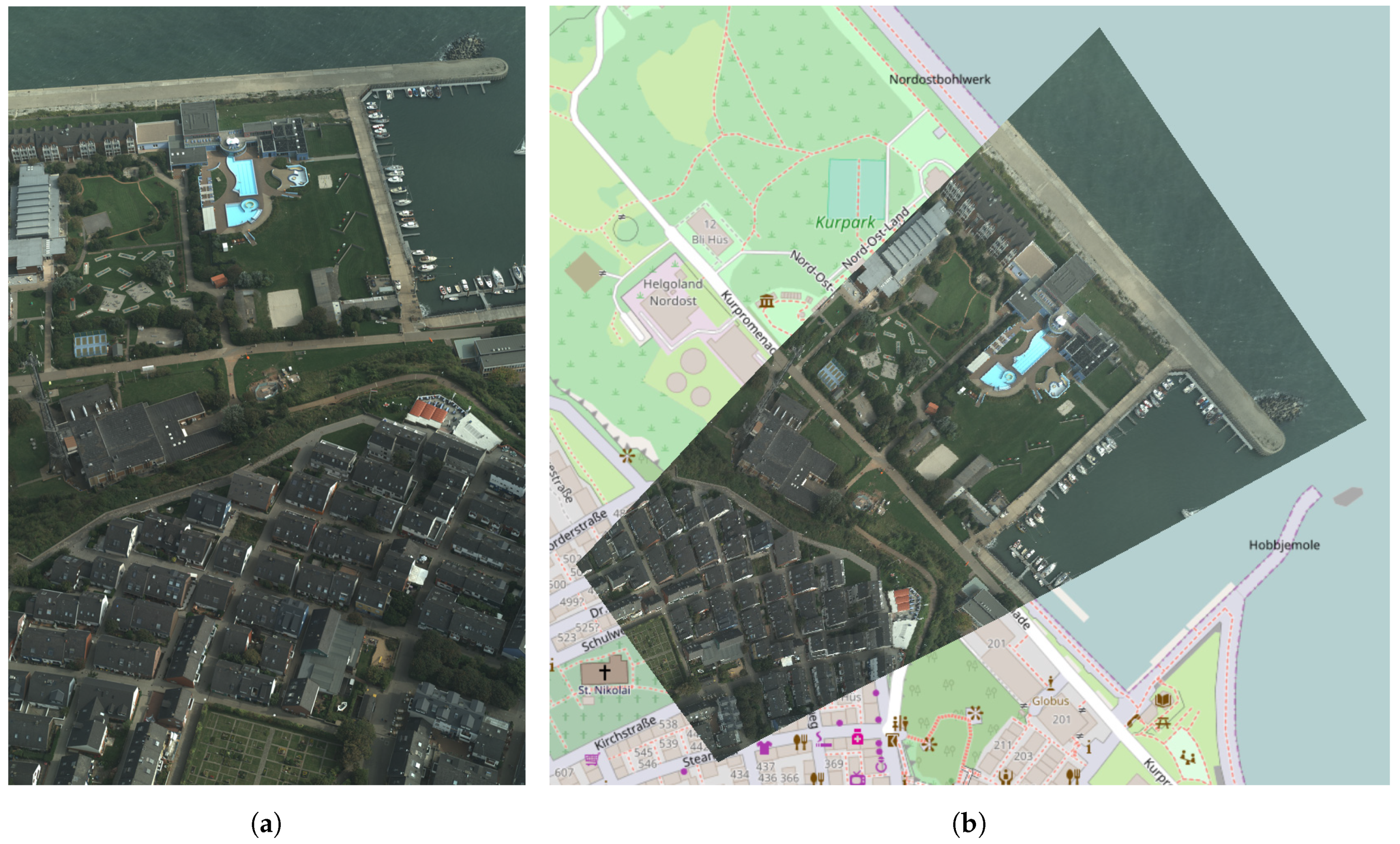
To draw an aerial image onto a map (i.e., a georeferenced coordinate system), we determine a projective mapping for every single image [21]. This mapping consists of a homogeneous transformation matrix, that specifies a mapping from image’s pixel coordinate system to the four-sided footprint polygon and thus to the targeted georeferenced coordinate system (i.e., map). The calculation of this 3 × 3 matrix basically derives from solution of a linear system of equations, that is formed by relationship between the four corner coordinates in both coordinate systems [36]. This finally defines, where source pixels from a specific image are to be drawn into the map [37]. A projective mapping sample is shown in Figure 9.
In the simplest implementation, one projection matrix is defined for each aerial image. For rather flat areas and nadir-looking aerial cameras, this simple mapping variant may already generate very good mosaics in terms of positional accuracy and coincidence between adjacent image tiles. However, projection accuracy can be increased by tiling the aerial image into a (rectangular) grid of image parts and determining an independent projection matrix for each of these tiles. This increases positional accuracy of the computed projections, in particular for highly structured areas such as mountains or deep valleys.
By sequentially drawing multiple aerial images using the appropriate transformation matrices, one obtains a seamless, georeferenced, quick mosaic of the captured area. Modern computer systems support hardware-accelerated transformation-based rendering. This allows a fast and smooth visualization of several hundreds up to several thousands of such aerial images within the corresponding scene.
2.8. Complexity and Estimation of Computational Effort
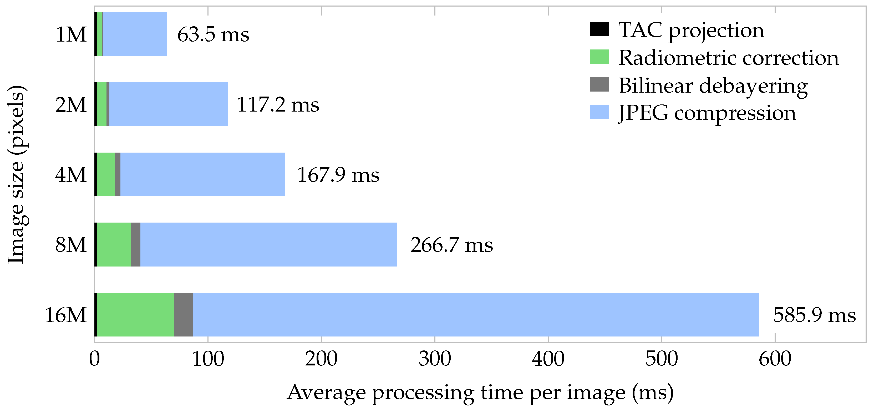
The presented approach has several processing stages, each with a specific computational demand. In the context of real-time applications, a key issue is the overall performance in a given set-up, especially for UAV applications with rather limited embedded computing systems. Figure 10 shows processing times of the presented approach as a function of input image size in pixels. Above all, this figure reveals two findings: First, the main computational effort is required for the JPEG compression stage, which accounts for about 85% of the overall computation time, followed by radiometric correction stage (~11.5%) and bilinear debayering (~2.5%). Second, the overall processing time is roughly linearly dependent on the image size: While TAC projection has virtually a constant processing time (the projection does not matter about the number of pixels), the processing times of the three remaining stages grow linearly by the number of image pixels to be processed.
Due to the linear complexity, a given system can be classified by the number of pixels that can be processed by the presented real-time processing chain per time. The required processing performance for a certain flight campaign configuration, i.e., the number of pixels to be processed per time (denominated as computational load in pixels per second) can roughly be estimated using the following formula:
where is the aircraft’s flight speed over ground in meters per second, is the sensor’s ground sampling distance in meters per pixel and the number of sensor pixels across the flight direction (generally the sensor width). The ground sampling distance of the camera sensor in turn depends on flight altitude (i.e., height above ground), cameras field of view and the sensor resolution in pixels. The formula represents a lower bound of the computational load and may be higher in the case of, e.g., increased aircraft movements, in particular around aircraft’s vertical axis. In practice, we experienced additional loads in the range of 5% to 10% on average, depending on aircraft, flight patterns and operational conditions.
2.9. Demonstration UAV Camera System
The first prototype of the UAV-based real-time mapping camera was developed in 2018 (see Figure 11a). The system incorporates an industrial camera, a dual-frequency GNSS receiver including inertial-aided attitude processing (INS), and an embedded computer. The camera head consists of a 16 MPix CCD sensor (ON Semiconductor KAI-16070 with Bayer pattern) and an industrial F-Mount lens (Schneider Kreuznach Xenon-Emerald 2.2/50). The aperture is set to f4.0 and the focus is fixed to the hyperfocal distance. Exterior orientation calculation is based on a dual-antenna GNSS receiver (Novatel OEM7720) in combination with an industrial grade MEMS-IMU (Epson G320N). The dual-antenna set-up is used to determine true-heading independently from INS. This improves the orientation accuracy, in particular when movement direction and heading do not correlate due to cross-wind. Depending on flight trajectory, differences of up to 10 degrees have been observed. Additionally, the dual-antenna system allows for very fast attitude initialization already on ground without aircraft movement. The distance (basis) between both GNSS antennas (mounted in the front and tail) is 1.2 m. The GNSS receiver continuously estimates position and attitude. The end-of-exposure signal is signaled to the GNSS receiver. Thus, every image is assigned with precisely measured time, position and orientation. Considering the interior camera calibration, direct georeferencing can be applied. Due to continuous synchronization of all subsystems, each image can be time-stamped with a precision better than 1 s. Time synchronization, image acquisition and real-time image processing is done by the embedded computing unit. This computer is powered by a Quad Core Processor (Intel Atom E3950) with 8 GB RAM and a solid state disk and runs a Linux operating system. In this configuration, the system allows capturing up to three raw images per second which can be stored on a removable storage device. The camera system is shown in Figure 11. It has a weight of 1.4 kg (including embedded PC, camera, IMU, GNSS receiver, GNSS antenna, power management and structure) and dimensions of 10 × 14 × 20 cm. The presented real-time processing chain was implemented on that system, handling an overall maximum performance load of about 32 MPix/s. Thus, the system is able to process and compress up to two full images per second (each with 16 MPix), or four half images (clipped by TAC) per second, and so on.
A vertical take-off and landing (VTOL) fixed wing UAV (see Figure 11b) is used as carrier providing a flight time of approximately 90 min at cruise speeds between 60 and 90 km/h. Thus, the carrier can travel a distance of up to 105 km per battery charge. It is specified with a maximum take-off weight (MTOW) of 14 kg including a payload of up to 2 kg and has a wingspan of 3.5 m. It can operate at wind speeds of up to 6 m/s and temperatures of 0–35 °C. While its typical flight operation altitude is in the range of 100–200 m AGL, it is capable of operating up to altitudes of 3000 m above sea level. The operational range is only limited by the maximum flight time because the autopilot systems allows fully automated flights beyond visual line of sight (BVLOS). This requires a predefined flight plan with terrain follow mode for security reasons. The UAV is equipped with a conventional command and control link as well as an additional mobile network radio for BVLOS operation. For safety reasons, this carrier is equipped with position lights and an integrated automatic dependent surveillance broadcast (ADS-B) transceiver.
3. Results
The development of the real-time processing chain was divided into two phases: First, the complete processing chain was developed and tested on a standard aerial imaging aircraft with application of a WiFi-based radio link. Afterwards, the real-time processing chain was ported to a miniaturized UAV-based camera system.
The first phase was successfully accomplished within an aircraft-based experiment in maritime environment, exercised in 2017 over the North Sea off Cuxhaven, Germany [38]. For data downlink, a civil WiFi-based radio link with pointing antennas on both sides was used (see Figure 12a). Image data provided by the real-time processing tool chain was transmitted to a ground control station 80 km away. An interactive map of the captured area was generated with a measured latency of approximately 2 s between image acquisition and visualization (see Figure 12b). It was shown that the redundancy optimized image data enables seamless real-time mapping of the recorded area with full geometric and radiometric resolution at an average data link rate of about 1–10 Mbit/s. The experiment covered a period of five days. Several flights were performed with single flight times up to a few hours. Throughout the experiment, roughly 12 GB of image data were processed and transmitted via the downlink. From these image data, real-time aerial maps were continuously rendered in the ground station, spanning a covered area of more than 100 km. Images lost due to temporary interruptions were filled as soon as the connection was reestablished.
Furthermore, the projection accuracy of the direct georeferencing approach was evaluated within this experiment. This was done by measuring projection errors of known ground control points (GCP) captured by aerial imagery from an altitude of 1300 m above sea level. The investigation provides an absolute spatial pixel accuracy of approximately 2 m (2) horizontally [39]. This level of projection accuracy with direct georeferencing can be considered sufficient for disaster assessment and management tasks.
In the second phase, a miniaturized version of the camera system for UAV-based applications was developed (see Figure 11a). The total weight of the system is 1.4 kg, including embedded mission computer with Intel Atom CPU. Overall dimension is about 10 × 14 × 20 cm. This camera system was integrated into a novel VTOL fixed-wing UAV (see Figure 11b). The overall system was tested in 2017 as part of an international UN rescue exercise to verify the technical feasibility and relevance of the concept, for example for On-Site Coordination Centers (OSOCC) [40]. Within this exercise, several medium-sized areas (up to a few square kilometers) were surveyed by the UAV system. After landing, instant aerial maps of the captured areas were generated using TAC algorithm (see Section 2.2) and provided to the relief and assessment teams.
In a final step, the real-time functionality is currently being implemented on this miniaturized UAV-based aerial camera system. Despite its performance limitations, the embedded system is already capable of running the complete real-time processing chain with a throughput of up to 32 MPix/s, or, respectively, two full frame images per second (see Section 2.8). To actually enable real-time mapping applications, the integration of a digital data link is currently being examined. Therefore, both infrastructure-based technologies (4G-LTE) and compact point-to-point data links are being investigated. A typical operation of the overall system is at a height of 200 m above the ground at a speed of 80 km/h and a frame rate of 2 Hz. This results in a capturing rate of about 3200 m per second with a swath width of 146 m and a GSD of 3 cm.
4. Discussion
The presented real-time processing chain is the basis for novel situation picture and mapping applications, which are particularly useful in the security field. It has already been demonstrated in several training scenarios together with rescue and relief forces and could significantly improve tasks such as operation coordination and disaster assessment. In contrast to usual photogrammetric approaches, georeferenced maps can already be generated during the flight, allowing to supply a situation picture or specific spatial information immediately. Due to its low computational complexity, the method is even applicable for UAV-based systems. On the other hand, the processing chain has specific requirements to incoming sensor data. Firstly, it relies on an adequate real-time position and orientation information for each single captured image. Secondly, it requires an on-board processing unit in order to execute the particular processing stages. Thus, the presented processing chain cannot be applied to arbitrary off-the-shelf reconnaissance UAV systems but requires an appropriate camera system payload.
Several modifications may improve map quality or extend the range of use cases. The proposed core algorithm is currently applied only on pairs of consecutively recorded images. In the case of meandering flight patterns or even arbitrarily arranged aerial images of a common area, it could be better to analyze and intersect each overlapping image pair to optimize the image areas to be rendered. Data structures such as quad-trees could be used to easily and quickly find the overlapping images within the set.
Another extension to our basic approach addresses the granularity of geometric projection. While the proposed TAC algorithm extracts one rectangular section for every single aerial image, a “tiling version” of this algorithm, possibly supporting level-of-detail (LOD) techniques, could extract several (distinct) image areas and their corresponding projection. This would increase the positional accuracy of the computed projections, in particular for highly structured areas like mountains or deep valleys.
Furthermore, the current implementations do not apply any further image registration procedures. Similar to the approach of Kekec et al. [41], lightweight image correlation methods could further enhance the real-time georeferencing solution. The overlap analysis performed with our algorithm could thereby restrict the image parts to be analyzed, which in turn would minimize the computational effort for the image co-registration methods.
Finally, we are also evaluating the application of fast and lightweight sparse matching techniques to derive an approximate elevation model already in real-time. This could eliminate the need for an a priori height model of the captured terrain. In addition, such a directly derived elevation model may provide a better spatial resolution and thus could enhance the overall quality of the generated real-time maps.
5. Patents
The Terrain Aware Image Clipping (TAC) algorithm has been patented by the German Patent- and Trademark Office (GPTO) under filer number DE 10 2016 224 886 B3 [42]. Since a requested International Preliminary Report on Patentability confirmed novelty and inventiveness of the proposed algorithm, further international patent applications are pending based on its international publication number WO 2018/108 711.
Author Contributions
Conceptualization, Daniel Hein, Thomas Kraft, Jörg Brauchle and Ralf Berger; methodology, Daniel Hein; software, Daniel Hein; validation, Daniel Hein, Thomas Kraft, Jörg Brauchle and Ralf Berger; formal analysis, Daniel Hein; investigation, Daniel Hein and Ralf Berger; resources, Thomas Kraft, Jörg Brauchle and Ralf Berger; data curation, Daniel Hein, Thomas Kraft and Jörg Brauchle; writing—original draft preparation, Daniel Hein, Thomas Kraft, Jörg Brauchle and Ralf Berger; writing—review and editing, Daniel Hein and Ralf Berger; visualization, Daniel Hein; supervision, Ralf Berger; project administration, Thomas Kraft, Jörg Brauchle and Ralf Berger; funding acquisition, Thomas Kraft, Jörg Brauchle and Ralf Berger.
Funding
This research was supported by the Program Coordination Defence & Security Research at DLR. Parts of the work were funded by the Federal Ministry of Research and Education (FKZ 13N12746).
Conflicts of Interest
The authors declare no conflict of interest.
Abbreviations
The following abbreviations are used in this manuscript:
| ADS-B | Automatic dependent surveillance-broadcast |
| BVLOS | Beyond visual line of sight |
| CCD | Charge-coupled device |
| DEM | Digital elevation model |
| DLR | Deutsches Zentrum für Luft- und Raumfahrt (German Aerospace Center) |
| DSNU | Dark signal non-uniformity |
| FIFO | First-in-first-out |
| GCP | Ground control point |
| GNSS | Global navigation satellite system |
| GPTO | German Patent- and Trademark Office |
| GSD | Ground sampling distance |
| IJG | Independent JPEG group |
| IMU | Inertial measurement unit |
| JPEG | Joint photographic experts group |
| LIFO | Last-in-first-out |
| LTE | Long term evolution |
| MACS | Modular Aerial Camera System |
| MTOW | Maximum take-off weight |
| OSOCC | On-site operations coordination center |
| PRNU | Photo response non-uniformity |
| RGB | Red-Green-Blue |
| ROI | Region of interest |
| SFM | Structure from motion |
| TAC | Terrain aware image clipping |
| TCP | Transmission control protocol |
| UAV | Unmanned aerial vehicle |
| UDP | User datagram protocol |
| VTOL | Vertical take-off and landing |
References
- United Nations Office for the Coordination of Humanitarian Affairs. UNDAC Field Handbook. Available online: https://www.unocha.org/sites/unocha/files/1823826E_web_pages.pdf (accessed on 6 May 2019).
- Tanner, V.D. Using Drones in Disaster Areas: Perspectives of Disaster Responders in North Carolina, Virginia and Maryland. Available online: http://thescholarship.ecu.edu/bitstream/handle/10342/7046/TANNER-MASTERSTHESIS-2018.pdf (accessed on 6 May 2019).
- Swiss Foundation for Mine Action (FSD). Drones in Humanitarian Action. Available online: http://drones.fsd.ch/en/independent-report-drones-are-ready-for-disasters (accessed on 6 May 2019).
- DuPlessis, J. Using Drones to Inspect Post-Earthquake Road Damage in Ecuador. Available online: http://drones.fsd.ch/wp-content/uploads/2016/11/13.Case-StudyEcuador3.pdf (accessed on 6 May 2019).
- Alschner, F.; DuPlessis, J.; Soesilo, D. Using Drone Imagery for Real-Time Information after Typhoon Haiyan in The Philippines. Available online: http://drones.fsd.ch/wp-content/uploads/2016/06/9Case-Study.Philippine.SearchRescue.3May2016.pdf (accessed on 6 May 2019).
- Swiss Foundation for Mine Action (FSD). Using Drones to Create Maps and Assess Building Damage in Ecuador. Available online: http://drones.fsd.ch/wp-content/uploads/2016/11/14.Case-StudyEcuador.pdf (accessed on 6 May 2019).
- Meier, P. Digital Humanitarians—How Big Data is Changing the Face of Humanitarian Response. Available online: http://www.digital-humanitarians.com/ (accessed on 6 May 2019).
- McFarland, M. In Nepal, a Model for Using Drones for Humanitarianism Emerges. Available online: https://www.washingtonpost.com/news/innovations/wp/2015/10/07/in-nepal-a-model-for-using-drones-for-humanitarianism-emerges (accessed on 6 May 2019).
- Ghosh, D.; Kaabouch, N. A survey on image mosaicing techniques. J. Vis. Commun. Image Represent. 2016, 34, 1–11. [Google Scholar] [CrossRef]
- Tjahjadi, M.; Handoko, F.; Sai, S. Novel image mosaicking of UAV’s imagery using collinearity condition. Int. J. Electr. Comput. Eng. 2017, 7, 1188–1196. [Google Scholar] [CrossRef]
- Pravenaa, S.; Menaka, R. A Methodical Review on Image Stitching and Video Stitching Techniques. Int. J. Appl. Eng. Res. 2016, 11, 3442–3448. [Google Scholar]
- Cubic MotionDSP Inc. Fast 2D Mapping from Video. Available online: https://www.motiondsp.com/software-and-subscription-pricing/isr-video-enhancement-software/ (accessed on 6 May 2019).
- Pix4D SA. Pix4Dmapper. Available online: https://pix4d.com (accessed on 6 May 2019).
- Agisoft LLC. Agisoft PhotoScan Professional. Available online: https://www.agisoft.com (accessed on 6 May 2019).
- Trimble Inc. Inpho UASMaster. Available online: https://geospatial.trimble.com (accessed on 6 May 2019).
- Tomasi, C.; Kanade, T. Shape and motion from image streams under orthography: A factorization method. Int. J. Comput. Vis. 1992, 9, 137–154. [Google Scholar] [CrossRef]
- Pollefeys, M.; Koch, R.; Gool, L.V. Self-Calibration and Metric Reconstruction Inspite of Varying and Unknown Intrinsic Camera Parameters. Int. J. Comput. Vis. 1999, 32, 7–25. [Google Scholar] [CrossRef]
- Brauchle, J.; Hein, D.; Berger, R. Detailed and Highly Accurate 3D Models of High Mountain Areas by the MACS-Himalaya Aerial Camera Platform. Int. Arch. Photogramm. Remote. Sens. 2015, XL-7/W, 1129–1136. [Google Scholar] [CrossRef]
- Kraft, T.; Gessner, M.; Meißner, H.; Przybilla, H.; Gerke, M. Vorstellung eines photogrammetrischen Kamerasystems für UAV’s mit hochgenauer GNSS/INS Information für standardisierte Verarbeitungsverfahren. In Photogrammetrie—Laserscanning—Optische 3D-Messtechnik: Oldenburger 3D Tage 2016; Luhmann, T., Schumacher, C., Eds.; Wichmann—VDE Verlag: Berlin, Germany, 2016. [Google Scholar]
- Kraft, T.; Geßner, M.; Meißner, H.; Przybilla, H.J.; Gerke, M. Introduction of a Photogrammetric Camera System for RPAS with Highly Accurate GNSS/IMU Information for Standardized Workflows. In Proceedings of the EuroCOW 2016, the European Calibration and Orientation Workshop (Volume XL-3/W4), Lausanne, Switzerland, 10–12 February 2016; pp. 71–75. [Google Scholar]
- Hein, D.; Bayer, S.; Berger, R.; Kraft, T.; Lesmeister, D. An Integrated Rapid Mapping System for Disaster Management. In Proceedings of the ISPRS Hannover Workshop: HRIGI 17 (Volume XLII-1/W1), Hannover, Germany, 6–9 June 2017; Copernicus Publications: Göttingen, Germany, 2017; Volume XLII-1, pp. 499–504. [Google Scholar]
- Hein, D.; Berger, R. Terrain Aware Image Clipping for Real-Time Aerial Mapping. In Proceedings of the ISPRS TCI Midterm Symposium—Innovative Sensing—From Sensors to Methods and Applications, Karlsruhe, Germany, 9–12 October 2018; Jutzi, B., Weinmann, M., Hinz, S., Eds.; ISPRS Annals of the Photogrammetry, Remote Sensing and Spatial Information Sciences; Copernicus Publications: Göttingen, Germany, 2018; Volume IV, pp. 61–68. [Google Scholar]
- The Shuttle Radar Topography Mission (SRTM). Available online: http://www2.jpl.nasa.gov/srtm (accessed on 6 May 2019).
- Weng, J.; Cohen, P.; Herniou, M. Camera calibration with distortion models and accuracy evaluation. IEEE Trans. Pattern Anal. Mach. Intell. 1992, 14, 965–980. [Google Scholar] [CrossRef]
- Kannala, J.; Brandt, S.S. A generic camera model and calibration method for conventional, wide-angle, and fish-eye lenses. IEEE Trans. Pattern Anal. Mach. Intell. 2006, 28, 1335–1340. [Google Scholar] [CrossRef] [PubMed]
- Kelcey, J.; Lucieer, A. Sensor Correction and Radiometric Calibration of a 6-BAND Multispectral Imaging Sensor for Uav Remote Sensing. Int. Arch. Photogramm. Remote. Sens. Spat. Inf. Sci. 2012, 393–398. [Google Scholar] [CrossRef]
- European Machine Vision Association (EMVA). EMVA Standard 1288 Release 3.1; EMVA: Genève, Switzerland, 2016. [Google Scholar] [CrossRef]
- Verma, N.; Mann, P. Survey on JPEG Image Compression. Int. J. Adv. Res. Comput. Sci. Softw. Eng. 2014, 4, 1072–1075. [Google Scholar]
- Aguilera, P. Comparison of Different Image Compression Formats; Research Report ECE533; Computer Aided Engineering, University of Wisconsin: Madison, WI, USA, 2006. [Google Scholar]
- Kaur, R. A Review of Image Compression Techniques. Int. J. Comput. Appl. 2016, 142, 8–11. [Google Scholar] [CrossRef]
- Al-Ani, M.; Awad, F. The JPEG image compression algorithm. Int. J. Adv. Eng. Technol. 2013, 6, 1055–1062. [Google Scholar]
- Independent JPEG Group. Available online: http://ijg.org (accessed on 6 May 2019).
- Postel, J. User Datagram Protocol; RFC-768; University of Southern Californica, Information Sciences Institute: Los Angeles, CA, USA, August 1980; Available online: https://www.rfc-editor.org/rfc/rfc768.txt (accessed on 6 May 2019).
- Braden, R. RFC 1122 Requirements for Internet Hosts—Communication Layers; Internet Engineering Task Force: Fremont, CA, USA, 1989. [Google Scholar]
- Peterson, L.L.; Davie, B.S. Computer Networks: A Systems Approach; Morgan Kaufmann Publishers Inc.: San Francisco, CA, USA, 1996. [Google Scholar]
- Heckbert, P. Fundamentals of Texture Mapping and Image Warping. Master’s Thesis, University of California Berkeley, Berkeley, CA, USA, 1989. [Google Scholar]
- Hartley, R.; Zisserman, A. Multiple View Geometry in Computer Vision, 2nd ed.; Cambridge University Press: Cambridge, UK, 2004. [Google Scholar]
- Brauchle, J.; Bayer, S.; Berger, R. Automatic Ship Detection on Multispectral and Thermal Infrared Aerial Images Using MACS-Mar Remote Sensing Platform. In Pacific-Rim Symposium on Image and Video Technology (PSIVT 2017); Satoh, S., Ngo, C.W., Yuan, J., Eds.; Springer Science: Berlin/Heidelberg, Germany, 2017. [Google Scholar]
- Brauchle, J.; Bayer, S.; Hein, D.; Berger, R.; Pless, S. MACS-Mar: A Real-Time Remote Sensing System for Maritime Security Applications. CEAS Space J. 2018, 11, 35–44. [Google Scholar] [CrossRef]
- Kraft, T.; Bayer, S.; Hein, D.; Stebner, K.; Lesmeister, D.; Berger, R. Echtzeit-Lagekarten für die Katastrophenhilfe. Vermessung mit Unbemannten Flugsystemen 2018, 89, 123–135. [Google Scholar]
- Kekec, T.; Yildirim, A.; Unel, M. A new approach to real-time mosaicing of aerial images. Robot. Auton. Syst. 2014, 62, 1755–1767. [Google Scholar] [CrossRef]
- Hein, D. Verfahren und Vorrichtung zur Ermittlung der Schnittkanten von zwei sich Uberlappenden Bildaufnahmen einer Oberfläche. German Patent No. DE102016224886B, 6 June 2016. [Google Scholar]
Figure 1.
Airborne segment of real-time processing chain. The particular processing stages are explained in Section 2.
Figure 1.
Airborne segment of real-time processing chain. The particular processing stages are explained in Section 2.

Figure 2.
Ground segment of real-time processing chain. The quad2quad rendering stage is explained in Section 2.7.
Figure 2.
Ground segment of real-time processing chain. The quad2quad rendering stage is explained in Section 2.7.

Figure 3.
Aerial imaging of a non-planar terrain and view cone overlap visualization (profile view): (a) full frame coverage and view cone overlap; and (b) minimized view cone overlap of clipped aerial images by application of TAC algorithm.
Figure 3.
Aerial imaging of a non-planar terrain and view cone overlap visualization (profile view): (a) full frame coverage and view cone overlap; and (b) minimized view cone overlap of clipped aerial images by application of TAC algorithm.

Figure 4.
Effect of radiometric correction at aerial image mosaicing. (a) Mosaic without radiometric correction; (b) Mosaic with model-based radiometric correction.
Figure 4.
Effect of radiometric correction at aerial image mosaicing. (a) Mosaic without radiometric correction; (b) Mosaic with model-based radiometric correction.

Figure 5.
Compression performance of libjpeg library, version 9b, depending on the JPEG quality setting. Values show average single-thread compression time and relative compression size of a 16 MPix (4864 × 3232 pixels) 12-bit aerial image. Comparison of processing times for an Intel i7-6800K desktop CPU and an embedded System with an Intel Atom E3950 CPU.

Figure 6.
JPEG compression result on sample aerial image with an image resolution of 4864 × 3232 pixels, 12-bit radiometric depth (which corresponds to a raw image data size of 22.5 MB), and a ground sampling distance (GSD) of 5 cm per pixel: (a,c) full image: and (b,d) detail view of the yellow rect section in the full image.

Figure 7.
Case study: Image data size of a sample scene comparing raw imagery, application of JPEG compression, application of TAC clipping and combined application of JPEG compression and TAC clipping. Sample scene comprising 63 aerial images captured by the demonstration UAV camera system. Length of captured scene: 1194 m; altitude: 322 m AGL; speed: 19 m/s (68 km/h); trigger rate: 1 Hz; and flight time: 63 s. Values below scene samples correspond to the data size of the rendered mosaic, the values in parentheses show the relative size compared to raw imagery size. JPEG compression with libjpeg library version 9b; quality setting: 1; and radiometric depth: 12-bit. Size of raw captured imagery is about 1.4 GB (c), which corresponds to a raw data rate of about 180 Mbit/s. By application of both JPEG compression and TAC clipping (f), the total size of the captured scene was reduced to 4.9 MB, which corresponds to a data rate of about 0.62 Mbit/s.

Figure 8.
Real-time data transmission chain. The control loop at airborne segment adjusts compression ratio depending on data link capacity (i.e., its current available bandwidth) and/or transmitter’s buffer fill level.
Figure 8.
Real-time data transmission chain. The control loop at airborne segment adjusts compression ratio depending on data link capacity (i.e., its current available bandwidth) and/or transmitter’s buffer fill level.

Figure 9.
Projective mapping: Single aerial image (a) and its perspective projection (b) by application of the corresponding transformation matrix.
Figure 9.
Projective mapping: Single aerial image (a) and its perspective projection (b) by application of the corresponding transformation matrix.

Figure 10.
Processing times for real-time processing chain (airborne segment), depending on image size. Results from processing an aerial image dataset comprising 1206 single images, captured by three different camera sensors, each with a 16 MPix Bayer pattern sensor. JPEG compression by libjpeg-library version 9b; radiometric depth: 12-bit; and quality setting: 5. Processing machine: standard desktop computer with an Intel i7-6800K CPU. The different image sizes were obtained by vertical symmetric cropping of original (full) images.

Figure 11.
(a) Real-time capable aerial camera system for UAV; and (b) VTOL carrier.

Figure 12.
Aircraft-based demonstration of real-time aerial mapping: (a) aircraft with DLR Modular Airborne Camera System (MACS) and WiFi-based 10 Mbit/s data downlink; and (b) generation of seamless aerial maps from the transmitted image data in real-time. The latency between image acquisition and visualization is about 2 s.

© 2019 by the authors. Licensee MDPI, Basel, Switzerland. This article is an open access article distributed under the terms and conditions of the Creative Commons Attribution (CC BY) license (http://creativecommons.org/licenses/by/4.0/).
Share and Cite
MDPI and ACS Style
Hein, D.; Kraft, T.; Brauchle, J.; Berger, R. Integrated UAV-Based Real-Time Mapping for Security Applications. ISPRS Int. J. Geo-Inf. 2019, 8, 219. https://0-doi-org.brum.beds.ac.uk/10.3390/ijgi8050219
AMA Style
Hein D, Kraft T, Brauchle J, Berger R. Integrated UAV-Based Real-Time Mapping for Security Applications. ISPRS International Journal of Geo-Information. 2019; 8(5):219. https://0-doi-org.brum.beds.ac.uk/10.3390/ijgi8050219
Chicago/Turabian StyleHein, Daniel, Thomas Kraft, Jörg Brauchle, and Ralf Berger. 2019. "Integrated UAV-Based Real-Time Mapping for Security Applications" ISPRS International Journal of Geo-Information 8, no. 5: 219. https://0-doi-org.brum.beds.ac.uk/10.3390/ijgi8050219
Note that from the first issue of 2016, this journal uses article numbers instead of page numbers. See further details here.