TOST: A Topological Semantic Model for GPS Trajectories Inside Road Networks


1
Hunan Key Laboratory of Geospatial Big Data Mining and Application, Hunan Normal University, Changsha 410081, China
2
College of Resources and Environmental Sciences, Hunan Normal University, Changsha 410081, China
*
Author to whom correspondence should be addressed.
ISPRS Int. J. Geo-Inf. 2019, 8(9), 410; https://0-doi-org.brum.beds.ac.uk/10.3390/ijgi8090410
Submission received: 21 July 2019
/
Revised: 4 September 2019
/
Accepted: 8 September 2019
/
Published: 12 September 2019
Abstract
:To organize trajectory data is a challenging issue for both studies on spatial databases and spatial data mining in the last decade, especially where there is semantic information involved. The high-level semantic features of trajectory data exploit human movement interrelated with geographic context, which is becoming increasingly important in representing and analyzing actual information contained in movements and further processing. This paper argues for a novel semantic trajectory model named TOST. It considers both semantic and geographic information of trajectory data happens along network infrastructure simultaneously. In TOST, a flexible intersection-based semantic representation is designed to express movement typically constrained by urban road networks by combining sets of local semantic details along the time axis. A relational schema based on this model was instantiated against real datasets, which illustrated the effectivity of our proposed model.
1. Introduction
In recent years, research on mobility data management has shifted its focus from raw trajectories to semantic information on movements. As a consequence, related works has extended trajectories analysis with understanding and representing semantic interpretation or behavioral features of moving objects. Trajectories are only meaningful when their spatial properties and contextual information about the movement is considered [1], which is known as the semantic enrichment of trajectory. Semantic information enriches movement description with background context and behaviorally significant elements, instead of using a stream of spatiotemporal (x,y,t) points. With integrated semantic information, researchers and staff can not only reduce the consumption on laborious statistical analyses and basic spatial processes of raw trajectory data, but also improve means of analyzing trajectories of moving objects in follow-up data mining.
Basically, semantic trajectories are trajectories that incorporate supplementary information [2], such as the weather conditions during a trip, the POIs visited by a tourist (museums, hotels), the activities (shopping, eating), etc. Thus, the primary concern of semantic trajectories is how to present trajectories with semantic information to specific parts of raw trajectories [3] and facilitate the understanding of behaviors during movements. In order to achieve this, novel approaches for modeling trajectories have to go one step further on expressivity. They may enrich a trajectory with either semantic annotations of specific parts of trajectories, such as moves and stops, or evolution of the context in which the movement takes place. In other words, a semantic trajectory model must allow enhancing the expressivity of raw trajectory data by integrating the spatial information with the semantic expression [4], and supporting complicated queries on trajectories.
Previous studies have made a major step ahead towards the effective and practical semantic trajectory model. However, important issues are still open. One of the major concerns is that existing approaches mainly focus on trajectory annotation, despite the intuitive topological relationships that may play an import role in real applications. That has significant consequences, especially queries covering spatio-temporal and semantic information cannot be straightforwardly executed by means of any single semantic trajectory model. For instance, even a simple query like “determine how many people turn around their cars inside the South Lushan Road” can lead to extremely complex executions. And this will be worse when multiple constraints are considered together.
Another important concern is to enhance the expressivity and flexibility in a semantic trajectory model. The model and framework should be generic enough for showing various patterns and qualities of movement data. Employing spatial infrastructure, such as the transportation network, for representing semantic trajectories has bridged the “gulf between and low-level observational data and high-level conceptual” [5]. It, to some extent, makes people pay more attention on semantics, and allows efficient indexing structures for moving objects [6]. However, straightforward compressing a trajectory into a sequence of elements of spatial infrastructure is inflexible and hard to express more detailed semantic information, such as topological relationships inside a road segment. For a more comprehensive solution, the integration of Spatio-temporal topological characteristics and contextual information is desirable.
In this paper, taking the issue described above into consideration, we proposed a novel intersection-based topological semantic model for trajectories inside Road Networks, called TOST. This topological semantic trajectory model can: (1) encapsulate raw GPS trajectory data; (2) express qualitative features of movements between trajectory and road network elements by means of topological invariants, providing a new research perspective of semantic trajectory modeling; (3) allow for a comparatively flexible and extensible representation for trajectory analyzing and querying.
The remainder of this paper is organized as follows. Section 2 provides a review of existing semantic trajectory modeling approaches. Section 3 outlines some basic concepts, for example, detailed definitions of raw trajectory and road network. Section 4 describes the framework and topological semantics of the new trajectory model. We present a database instantiation of the proposed model in Section 5 and discuss our conclusions and future work in Section 6.
2. Related Work
In this section, we provide a survey of semantic trajectories described and analyzed in the literature. Early studies on trajectory modeling consists in the description of the movement of an identifiable moving objects [7]. Trajectory data modeling of course has fascinated scholars starting with existing common spatiotemporal data models (e.g., ST USM [8]; Percetory [9]; spatiotemporal ODMG [10]), particularly in the field of database, and expressly proposing novel trajectory models to moving objects (e.g., N. Pelekis, B. Theodoulidis and Y. Theodoridis [11]; H. Hajari and F. Hakimpour [12]). These studies provides efficient data management and mining techniques on raw trajectory data, and calls for novel methods and technologies for understanding trajectory data [13]. More recently, a number of trajectory models were proposed to define trajectories from a more semantic point of view [14]. These works on semantic enrichment of trajectory data can be classified into two categories: reconstructing trajectories by detecting behavioral features of moving objects and representing trajectories by correlating them to context data.
Reconstructing trajectories by means of behavioral features focuses on extracting some key spatial behaviors during the movement and annotates them with high-level semantics [14]. S. Spaccapietra et al. [15] first proposed stop-and-move model by describing the semantic trajectory as a chain of stop in which the trajectory temporarily suspends moving for certain time duration. Yan Z. et al. [16] completed a platform to reconstruct semantic trajectories by computing stops and moves from raw trajectory data. C. Parent et al. tried to annotate the trajectory with places of interest (POIs) and activities [17]. V. Bogorny et al. [14] and C. Parent et al. [18] extended the stop-and-move framework by employing more semantic elements. C. Renso et al. [19] formalized a semantic-enriched KDD process for understanding patterns of human behavior. R.H. Güting et al. [20] proposed a generic trajectory model, called symbolic trajectories, which integrates semantic information in form of a time dependent label. The main drawback of these models is that understanding of trajectories could be less persuasive without considering contexts. For example, it is hardly to tell normal detours from anomaly spatio-temporal patterns without awareness of speed limits of specific road segments as well as a traffic jam. As a result, recent studies on semantic trajectory becoming simpler on the basis of associations between trajectories and surrounding contexts.
Correlating trajectories to context data aims at integrating the spatial dimension of human movement with relevant environmental information, typically referring to transportation networks. F. Schmid et al. [5] mapped the raw trajectory data to the urban transport network, then represented the movements by time-stamping along vertices and edges with semantic annotations. J. Greenfeld et al. [21] presented a matching procedure based on topological relationships between street segments. Mohammed A. Quddus et al. in references [22,23,24] introduced their efforts to work out how to effective perform map-matching. Y. Lou et al. [25] worked to resolve map-matching for low-sampling-rate GPS trajectories. R. Fileto et al. [26] presented methods to associate to a raw trajectory with instances described in Linked Open Data (LOD). Wu F. et al. [27] tried to combine raw trajectory data with surrounding context data, in a more accurate way, by capturing individual preferences from historical dataset. Xiang L. et al. [28] opened up a way to depict movements as a sequence of local topologies between trajectory data and regions. H. Issa [2] proposed the spatio-textual trajectory model for filling the lack of contextual data in symbolic trajectory model. D. Tiesyte et al. [29] designed an index structure for similarity queries on floating car trajectory data, which replace complex arcs of tracks with linear edges of network. Also, K. F. Richter et al. [30] proposed to compress the raw trajectories in an urban environment by using available links of transportation networks.
Actually, it is the related research activities mentioned above that motived us to design a topological semantic trajectory model in our work for representing movements inside a road network. Most of previous works take directional and distance relations into account, without considering topological characteristics between trajectories and contexts. In this paper, we open up a new way to the semantic trajectory inside road networks, identifying intersection-based topological semantic description between trajectories and 2 basic road network elements (i.e., node and edge). First, we define comparatively flexible conceptual data model for topological semantic trajectories. To the best of the authors’ knowledge, semantic information of topology was first proposed in modeling semantic trajectories. After that, we construct a new, intersection-based, local topologies representation method. Finally, we use our model to improve expressivity and the query execution on trajectory data.
3. Basic Concepts
In this section, we show the definitions of raw trajectory, and road network, based on the definitions in Reference [1]. These definitions will be used in the rest of this paper.
Definition 1
(Raw Trajectory). A raw trajectory T is a sequence of time-stamped location points, denoted as , where is the ith sampling point on spatial positions in geographical space, denoted as or .
Definition 2
(Sub-Trajectory). A sub-trajectory SubT is a consecutive subsequence of a raw trajectory T, denoted as , where and .
A raw trajectory shows a path that a moving object follows on certain space-time. It is a typical spatial-temporal concept, which describes a consecutive movement of certain object over a period of time. From the view of space, the position of a moving object may be changing continuously, which makes it differing from a static object. From the view of time, traveling from one position to another takes a finite amount of time [26].
A raw trajectory can be divided into different segments, called sub-trajectories. A sub-trajectory is, of course, a sequence of time-stamped location points, which means the object remaining in a particular motion during the interval from the first point of the sub-trajectory to its last point. Once sub-trajectories are associated with object behaviors with special semantic information or external annotation (e.g., a POI like a specific street address), we can call them semantic segments in some literature [31]. Such semantic information is manifold, which can either be behaviors of the moving object like stopping at some place, or be in form of environment information, such as POIs relevant to the trace [32]. Then a sequence of these semantic segments is a semantic trajectory.
Since the sub-trajectory can be according to different concerns of investigators, it is possible to represent spatio-temporal semantic information of a trajectory at multifarious levels of granularity. For example, one can either reconstruct a trajectory by a set of sub-trajectories labeled as “stops” and “moves”. if the focus is on basic movement changes of the object itself. Such information can be inferred by associating with the knowledge base relevant to a concrete situation.
Definition 3
(Sematnic Trajectory). A semantic trajectory is a reorganized trajectory data based on a set of geographical semantic associations, note as , where is the ith sub-trajectory associated with particular semantic information.
Another set of key concepts for our study is about road network data. Obviously, significant portions of moving objects in the physical world locate in a constrained space. The variety of the surrounding environment of a location calls for concrete consideration of semantic understanding of trajectories [31]. The vast majority of GPS traces available in reality happens inside transportation networks [5], such as highways and railroads, instead of in a free space. It’s a basic fact of moving objects that their routes are correlated with or influenced by the surrounding traffic environment. Therefore, studying on trajectories should not only fixate on trajectory data, but also enable utilization of environmental information which help to enrich the semantic understanding of moving objects.
Definition 4
(Road Network). A road network is a directed graph embedded in , where N is the collection of graph nodes corresponding to traffic junctions in the geographic space, and E is the collection of graph edges that corresponds to road segments between junctions. A node of graph G, denoted by n, is defined as , where is the identifier of n, and the latter two attributes describe corresponding coordinates. A edge of graph G, denoted by e, is defined as , where is the identifier of e, is the first node identifier of e, is the second node identifier of e.
The vast majority of GPS traces available in reality happens inside transportation networks [20], such as highways and railroads, instead of in a free space. Since the coverage of modern transportation networks have extended throughout the world, it is difficult to discuss movements without traffic network structures, especially in the urban areas. A road network describes the geometry and topology information of roads by a combination of edges and nodes, as in many typical map projects. In addition to its geometric attributes, each edge in the graph has two significant attributes: the first node and the second node, and each node has two elementary attributes: the latitude and longitude. It is important to notice that an edge (i.e., road segment) can be either a unidirectional road or a bidirectional road and a node can allow either entering an edge or leaving an edge.
Road networks reduce the dimensionality of activity space of moving objects, thus, allow describing a trajectory by referring elements of the network. This is a popular representation for compressing a large number of sample points of a raw trajectory. By doing so, a trajectory can be simplified to a sequence of interconnected edges and nodes, and conveniently associated with meaningful annotations. In one sense, analyzing trajectory has been converted to spatial network analysis. However, focusing on depicting the geometry of sub-trajectories by combining network elements may not be the right direction. First, the evolving spatial relationships between trajectories and specific network elements will be ignored, if they are replaced by topological structures between network elements. For example, it is difficult that express a heading-back inside the same road edge by existing spatial network analysis methods. Second, sub-trajectories that don’t locate in existing road network data will be another challenge. Finally, extensibility is also an issue. It’s not effective in depicting more detailed semantic like “stopping at a certain position”. The proposed trajectory model need to include both standard and customizable constructs with maximum flexibility that can be easily tailored to the specific semantics of trajectories in a given application context [3].
It is noteworthy that the model we propose in this paper does not explicitly take into consideration the uncertainty of the trajectory data, i.e., noise, errors brought by measurement and sampling processes. The proposed model and related operations are built in assumptions that data have been appropriately cleaned by state-of-the-art techniques, since these topics are a large area and several approaches have been proposed, for example, Schussler et al. [33], Kuijpers et al. [34] and Pelekis et al. [35].
4. A Topological Semantic Model for Trajectories inside Road Networks
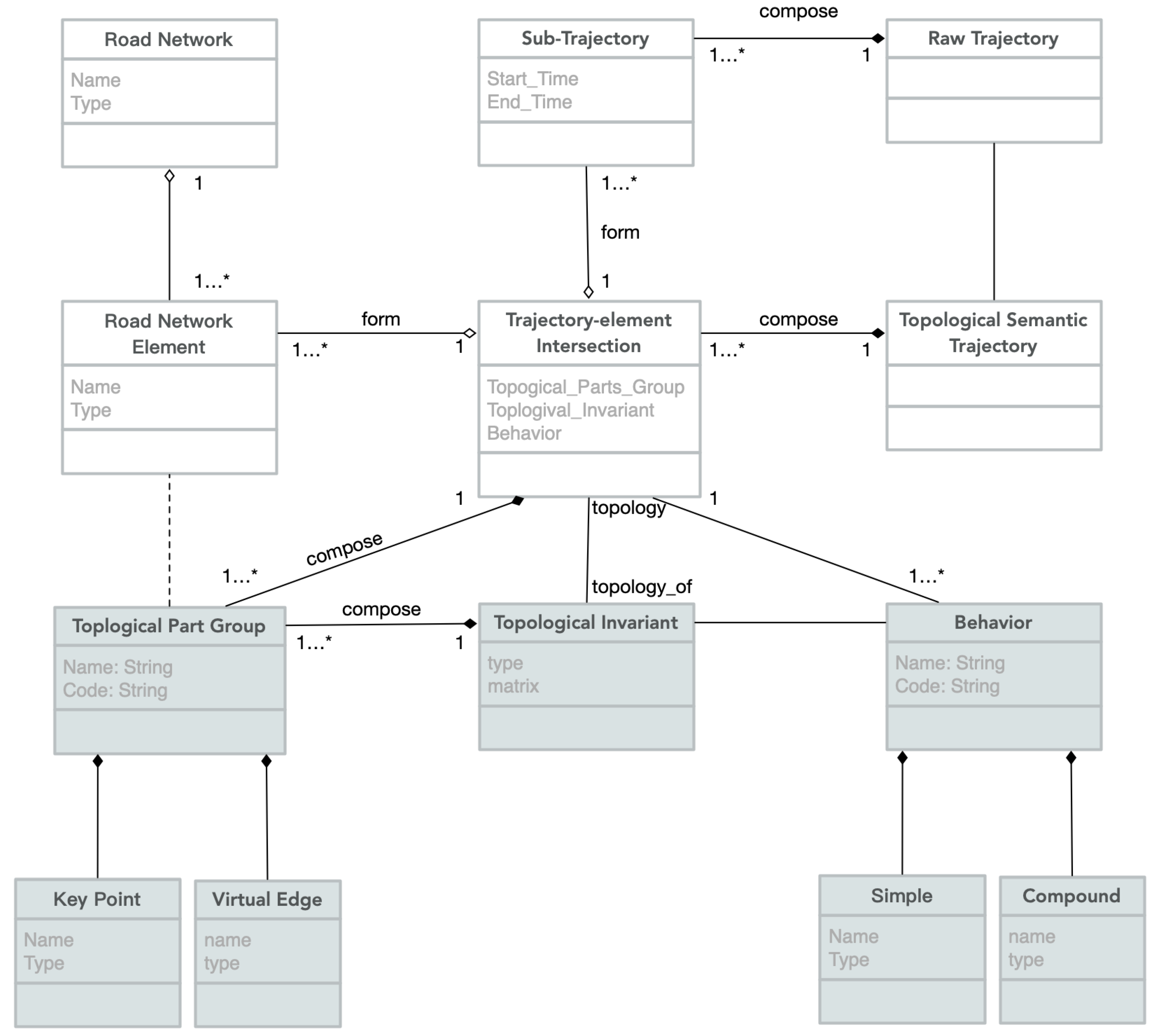
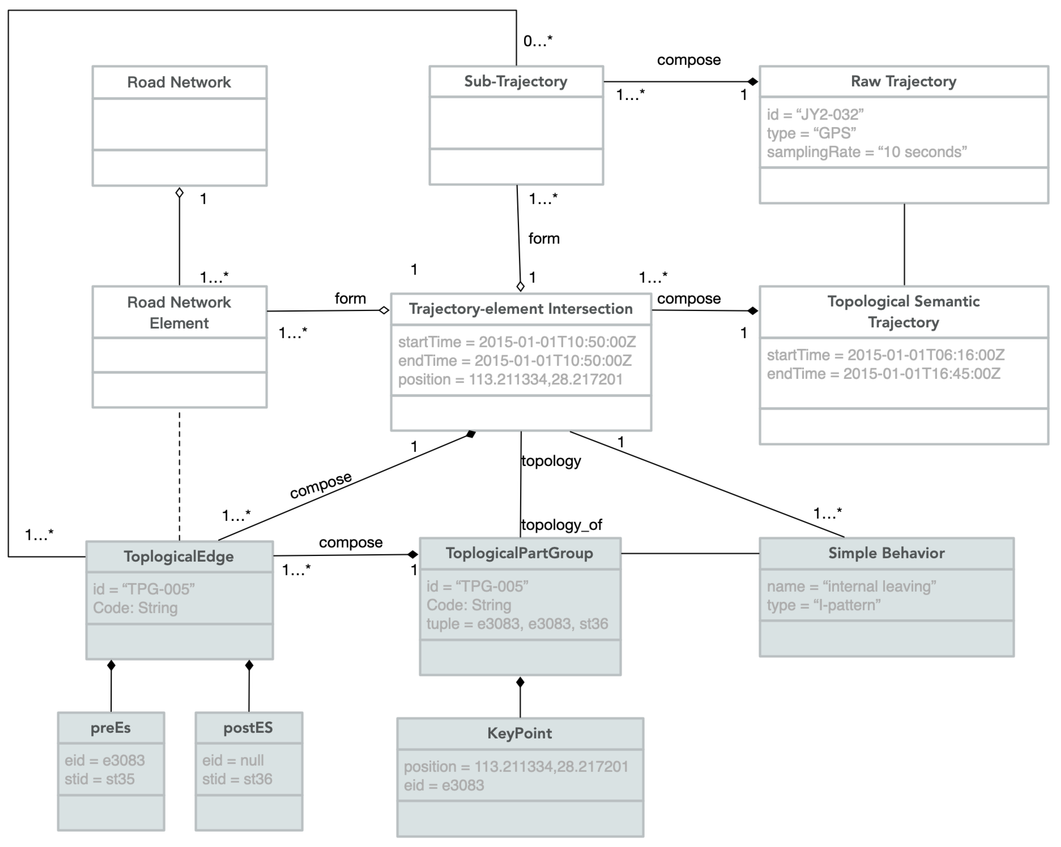
The core idea of this paper is to depict implicit topologies between sub-trajectories and network elements and explicitly integrate them with other semantic information. Figure 1 shows the conceptual data model for representing topological semantic trajectories inside road networks.
The model can be divided into two parts: (1) the first part (the non-shaded classes) covers the information related to: the raw trajectory, the sub-trajectory, the topological semantic trajectory, the trajectory-element intersection, the road network, and the road network element,(this part is detailed in Section 4.1); (2) the second part (the shaded classes) includes the topological invariant, the topology part group, the key-point, and the virtual edge, the behavior (this part is detailed in Section 4.2).
It is noticeable that the model can be used as an organized data representation set for the knowledge discovery process besides representing topological semantic information with respect to trajectories. It may benefit the discovery of more meaningful mobility patterns such as the reasons for an anomaly (e.g., traffic jam), or a more accurate profiling for different kinds of moving objects based on their semantic similarity. In other words, this model provides a semantic understanding of trajectories for trajectory data mining from a new perspective.
4.1. Representations for Trajectories inside Road Network
Time-dependent topological semantic information between a trajectory and elements characterize the movements of the trajectory in the context of a road network. Therefore, it can provide significant spatio-temporal information for relevant research within the realm of Geographic Information Science (GIS). From this point of view, the topological semantic trajectory represents the topological semantic enriched trajectories which are composed of the trajectory-element intersections that generated by associating sub-trajectories with road network elements. A raw trajectory will be a topological semantic trajectory only if it is split into sub-trajectories by local topological relationship, which are associated to a set of topological invariants and behaviors. A topological semantic trajectory is defined according to Definition 5.
Definition 5
(Topological Semantic Trajectory). A topological semantic trajectory is a reorganized trajectory data based on a set of sub-trajectories and trajectory-element intersections, note as , where is a set of sub-trajectories and is a set of trajectory-element intersections by sweeping road network elements along the raw trajectory.
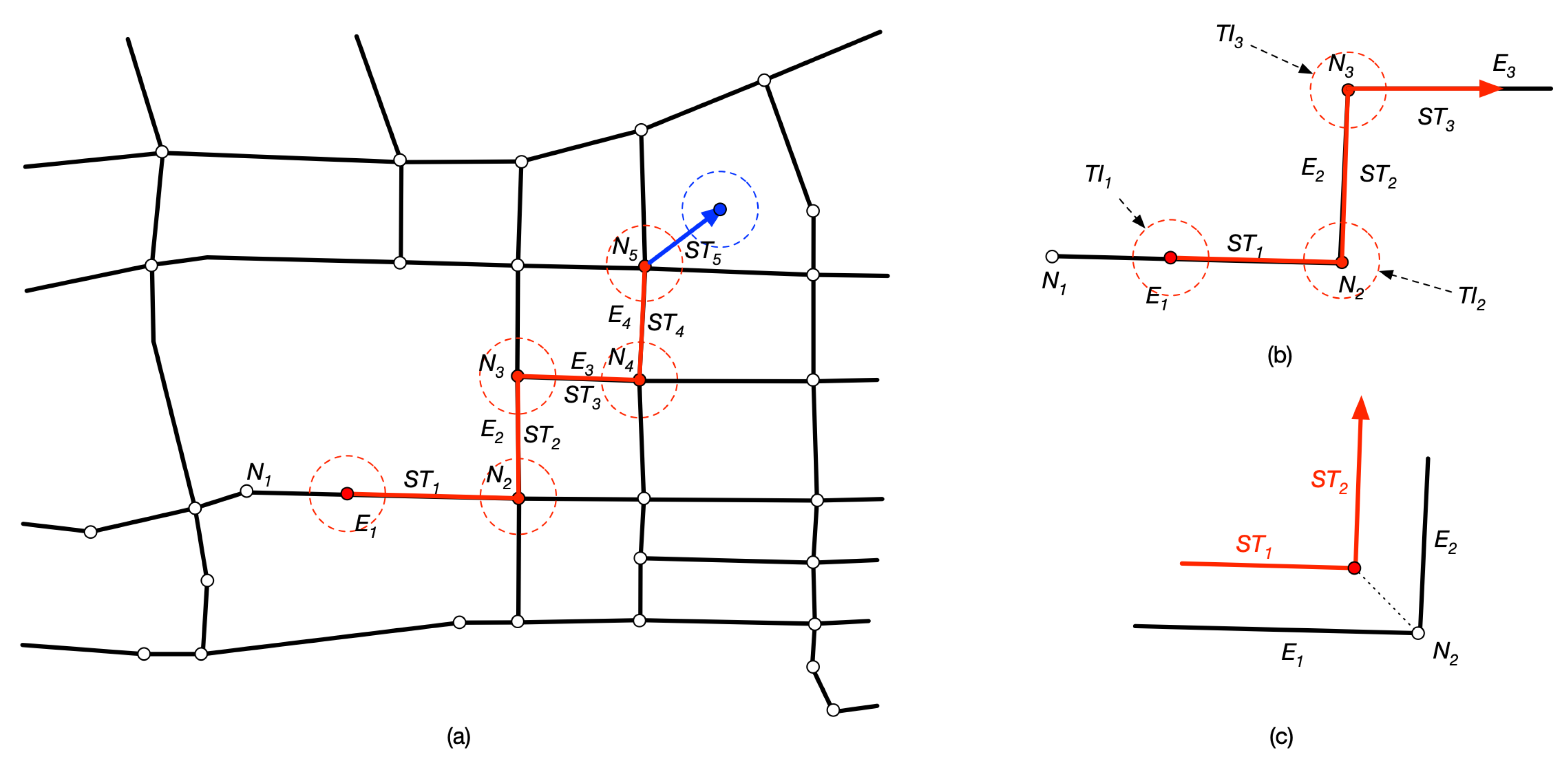
Each topological semantic trajectory has at least one sub-trajectory in its , as well as two trajectory-element intersections in its . Sub-trajectories are the trunks of a topological semantic trajectory. The duration of a sub-trajectory can be estimated by extracting the temporal information from its first point to the last point. Trajectory-element intersections are joints linking sub-trajectories in different directions. As shown in Figure 2a, the topological semantic trajectory can be seen as a chain of trajectory-element intersections and sub-trajectories. A trajectory-element intersection means that topological semantic information between trajectory and nodes or edges has changed during the movement. These changes in semantic are commonly associated with meaningful behaviors, such as “enter”, “leave”, or “stop”. In our proposed model, a trajectory-element intersection is defined according to Definition 6.
Definition 6
(Trajectory-element Intersection). A trajectory-element intersection is a junction of a topological semantic trajectory, denoted by , where is a group of topological parts, is the topological invariant corresponding to the topological part group, and B is the behavior of the trajectory-element intersection.
A trajectory-element intersection has a group of topological parts located in parts of the trajectory and certain road network elements. The topological part group, as shown in Figure 2c, describes the physical structure of a trajectory-element intersection which is constructed around a key point, which differentiates contiguous sub-trajectories coinciding with network elements. A trajectory-element intersection of the topological semantic trajectory can be either integrated with the classical “Stop/Move” trajectory model or other specific semantic information. For instance, the behavior of a trajectory-element intersection can either presents stops and moves or other information like transportation means. (The topological group, topological invariant and behavior will be detailed in Section 4.2.)
In the vast majority of cases, trajectory-element intersections are attached to nodes of a network (marked with red dots in Figure 2a). Sometimes, however, a trajectory-element intersection may also appear inside an edge, especially for the first or last intersection (marked with blue dots in Figure 2a). For a trajectory-element intersection on a node it must have at least two topological invariants corresponding to different elements respectively. For those trajectory-element intersections inside an edge, there will be more complex topological semantic information which will be discussed in Section 4.2.
During a trip, a trajectory-element intersection occurs each time the moving object enters, leaves or passes an element of road networks. For instance, as shown in Figure 2b that the object started its motion from edge , and entered edge by node , then moved along before left it through node , three trajectory-element intersections will be triggered at , and respectively. In other words, a trajectory-element intersection always takes place around a 0-dimensional point in which a local topological relation between the trajectory and an element changes. One can see that a trajectory-element intersection occurs in a topological semantic trajectory is a local topological invariant.
With this topological semantic trajectory representation one can easily perform common spatio-temproal analysis, such as inferring the spatio-temporal relationship between a trajectory and any specific road node or road segment at a particular period of time. As a common example, consider a temporal interval ranging from 9 p.m. to 10 p.m., all intersections appeared during this interval will be involved, and sub-trajectories have spatial relationships with related road nodes and road segments. Also, it can help to analyze the trajectory at higher level. For instance, consider an intersection in the middle of an edge. Having this information, one may infer an “invisible” road segment if it is neither the first nor the last intersection.
4.2. Topological Sematnics Related to Trajectory-element Intersections
Every topological-element intersection has Topological Part Group, Topological Invariants and Behaviors. The topological part group represents the physical composition of a trajectory-element intersection that contains related components, for example: node, edge, sub-trajectory. Their topological semantic information is determined through N-intersection Matrix of topological invariants [22], since nodes and edges can be seen as the simplest topological entities. And behavior has set characteristics that help to understand how and why a moving object is there.
4.2.1. Topological Part Group
Each trajectory-element intersection has a topological part group, since it always consists of several topological parts. The topological part group of an intersection includes all involved components from both parts of the trajectory and elements of the road network. The topological part group describes the location for the trajectory-element intersection, or, in another word, it shows where the moving object changes its routine.
Generally, a topological part group locates in a node or edge, so road network elements are essential components of the group. For instance, if a trajectory moves from one edge to another, a trajectory-element intersection would have a topological part group including these two edges as well as the node between them. However, sometimes a topological part group may locate in the road network. For example, a trajectory starts from the outside of the road network structure. A definition for topological part group is presented in Definition 8.
Definition 7
(Topological Part Group). A topological part group is a tuple , where is the core point of the group, is a set of an edge and a sub-trajectory before the , and is a set of an edge and a sub-trajectory after the . A of a group is defined as , where is the identifier of , is the identifier of an element that the locates in, and is keyPoint’s coordinates. A (or ) of group is defined as , where is the identifier of the related edge of network, is the identifier of the related sub-trajectory.
The concept of topological part group is crucial for establishing the local topologies between a trajectory and the road network. Each topological part group is a collection of triples including three components——that occur in chronological order. For a trajectory-element intersection to exist its topological part group must include a keyPoint and at least either one of the other two. The and contains two basic attributes: the sub-trajectory ID, the edge ID, and the keyPoint contains three basic attributes: the keyPoint ID, the element ID and the location of keyPoint. In normal condition, a (or ) may be either a subset including a sub-trajectory and an edge or an empty subset, which means a sub-trajectory (if it exists) be associated with an edge. Particularly the (or ) will be empty while the (or ) must exist, if the intersection occurs at the starting (or ending) point of the whole trajectory. And a can locate in either an edge or a node.
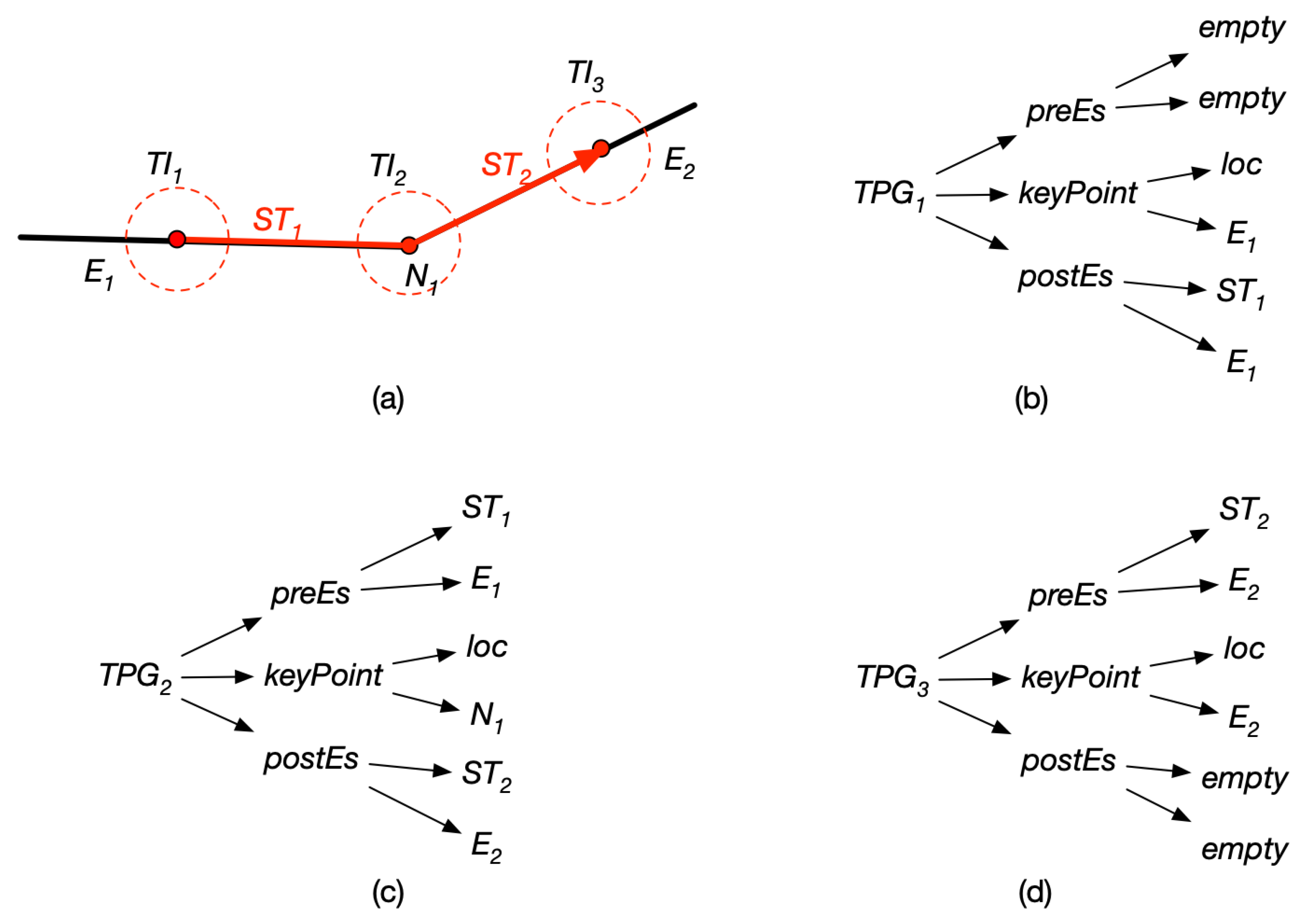
Figure 3 illustrates three typical trajectory-element intersections (i.e., , and ) and their topological part groups (i.e., , and ). Consider Figure 3a, the object started from the edge , then entered edge by node , and finally ended at the edge . In Figure 3b, the of the is an empty subset (accordingly, the locates in the starting point of the whole trajectory) and the of the is an empty subset as shown in Figure 3d (accordingly, the locates in the ending point of the whole trajectory). The , however, correspondingly owns a complete group, i.e., in Figure 3c. One can see that there are correlations between local topologies within trajectory-element intersections and values of its topological part group components, which will be discussed in detail in Section 4.2.2.
It is noteworthy that in the case of anomalies, such as missing parts of road data or driving violations, there may be no corresponding elements in the group (marked as blue line in Figure 2a). Under these circumstances, the corresponding part of the group contains only a piece of sub-trajectory.
4.2.2. Intersection Topological Invariant
As mentioned above, elements of a road network are referred to edges and nodes, which means they can be regarded as simple two-dimensional lines and points when discussing local topology in R2. And because the line and two nodes are interdependent in this net structure, it is inappropriate to tell the two apart in the topological invariant of the same trajectory-element intersection. Taking all these into consideration, this article presents the study in focusing on three topological parts from a topological part group instead of any single network element.
The characteristics of trajectory-element intersections are described by all subsets within corresponding topological part groups. Therefore, it is crucial to compute relation of each subset before discussing semantic information of intersection topological invariant. From this perspective, a nested tuple framework and a collection of tuple operations are designed for modeling the local topology within a trajectory-element intersection. Let be the topological part group of a trajectory-element intersection . Then can be expressed as a nested tuple (as shown in (1)). Sub-tuples of respectively represent different topological parts. For instance, the sub-tuple consisting of and corresponds to the . Three of these sub-tuples describe the intersection topological invariant together. For the nested tuple, each set describes a unique intersection topological invariant, and intersections with the same specifications will be considered as topological equivalence. If each item of these sub-tuples is characterized by either an empty value (∅) or a non-empty value (), there may be patterns described by a sub-tuple. By that analogy, there may be 26 = 64 patterns for the whole topological part group. However, not all of ith patterns practically make sense for the trajectory-network scenario in . For example, the cannot be empty for any trajectory-element intersection to exist.
Intuitively, each sub-tuple matches one topological part of a trajectory-element intersection if it describes a possible invariant conform to reality. The can be a valid intersection topological invariant by satisfying the following propositions:
Proposition 1.
.
Proposition 2.
.
Proposition 3.
If , then cannot be value of ∅ at the same intersection.
Proposition 4.
If , then cannot be value of ∅ at the same intersection.
These propositions follow from the definition of the trajectory-element intersection, which ensures the validity of an underlying trajectory-element intersection. Nevertheless, focusing on the value of empty or non-empty seems insufficient for discussing detailed semantic information in road network circumstances. Take for example the sub-tuple , which will result in losing information of the specific element if is simply assigned a value of . Therefore, it is clear that the binary properties (∅ and ) should be extended. Furthermore, there must be a set of calculation operations to determine the intersection topological invariants.
In this article, object identifiers are introduced instead of the non-empty value . Therefore, an item of a sub-tuple is either empty or an identifier. Since the trajectory-element intersection is defined in terms of topological invariants, it follows that the topological semantic information between the trajectory and network elements in is the synthesis of invariants with respect to all topological parts. This promotes our focus of determining individual invariants to depict topological semantic information. Given a topological part group, the intersection topological invariant is determined through the expression (1), such that:
- and
- and
- and
- .
A tuple operation is designed to match sub-tuples with corresponding invariants, which returns substitutions defined as follows:
where the first parameter denotes a sub-trajectory or the keyPoint, and the second parameter denotes an element. The match rules can be briefly explained as follows. A sub-tuple will be assigned empty if the corresponding sub-trajectory is empty; a sub-tuple will be assigned a sub-trajectory identifier if the corresponding element is empty while its sub-trajectory is non-empty; a sub-tuple will be assigned an element identifier if both parameters are non-empty.
With the operation match, the original tuple (1) can be converted to tuple (2), which consists of three matching operations on corresponding sub-tuples from (1) respectively. Each item of (2) describe the local topological relationship between two parts of the same sub-tuples from (1) in form of a matching result. For the tuple (2), each item is characterized by one of the three optional values: ∅, and (i.e., or ). These three items present all topological parts of a trajectory-element intersection in turn. If any topological part does not have a sub-trajectory, it is labeled as ∅ accordingly. Otherwise, it is labeled as a or .
Obviously, it schematizes trajectory-element intersections based on their topological parts over temporal logic. As shown in Figure 4, eight patterns are identified qualitatively to cover all cases of trajectory-element intersections. According to relative positions of intersections and the trajectory, the eight patterns can be further classified into three types: initial intersection, terminal intersection and basic intersection.
Initial Intersection. Given a trajectory-element intersection, it is called an initial intersection if the corresponding locates in the starting point of the trajectory (as shown in Figure 4a,b), which is given through a tuple in the form of .
Terminal Intersection. Given a trajectory-element intersection, it is called a terminal intersection if the corresponding locates in the terminating point of the trajectory (as shown in Figure 4c,d), which is given through a tuple in the form of .
Basic Intersection. Given a trajectory-element intersection, it is called a basic intersection if the corresponding locates in any position of the trajectory except the starting and terminating points (as shown in Figure 4e–h), which is given through a tuple in the form of .
One can obtain from Figure 4 that there exist totally seventeen distinct situations for trajectory-element intersections when specific elements are considered, which are summarized in Table 1. According to the table, the eight patterns mentioned above can be easily extended to seventeen more detailed initiations. In general, for any of these initiations, items ( and ) indicates the specific element where the or sub-trajectories locate in. Take the tuple expression of (, , ) as an example, the intersection means that the object moved along an edge (identified by ) before entering another edge (identified by ) by their mutual node (identified by ). However, note that certain tuple initiations in Table 1 contain items with value of identifiers of sub-trajectories. For these situations, though the intersections are still valid, they imply a kind of special case in which there is no suitable element matching with sub-trajectory. For instance, the tuple expression of (, , ) means that the object is not moving in the known road network and its route crosses an edge. The reason for this is manifold, ranging from the object running abnormally, to the road network missing corresponding road segments.
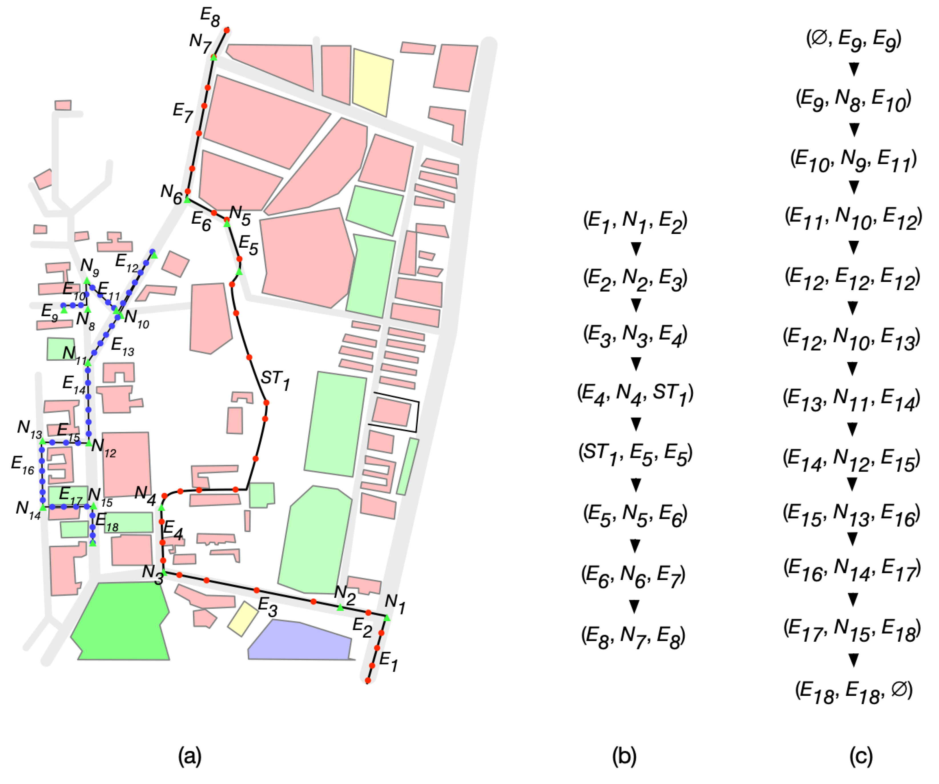
Depending on these settings, one can generate semantic trajectories considering sub-trajectories for each trajectory-element intersection triggered during the trajectory. For instance, let us consider the example in Figure 5a, where two real GPS trajectories are presented. The red-dotted line shows a teacher’s trip (drive to college, work all morning, drive across campus, then leave the campus), while blue-dotted line depicts a student’s trip (walk to laboratory, go to the dining hall, then walk out to take subway). These two trajectories are actually the manually processed results, in which noise was removed, track points were matched to real positions inside the road network and intersections were labelled (marked as green triangles). Then the teacher’s trajectory can be reorganized around the eight trajectory-element intersections shown in Figure 5b, and the student’s trajectory can be reorganized around the twelve trajectory-element intersections shown in Figure 5c. Obviously, any trajectory should be at least pretreated through three steps before it can be reorganized: noise removing, map-matching and spatio-joining. These pretreatments are challenging and time consuming to some extent, yet they are outside of the scope of this article and will discussed in our future work.
Plenty of information can be parsed in regard to the movement of these two trajectories within the road network structure. In this example, the teacher changed his mobility pattern for eight times during the trip (eight trajectory-element intersections), which means it switched from one road segment to another (or to where there were no roads) eight times. And the student started her trip from a road segment (i.e., ) and ended at another road segment (i.e., ), covering twelve trajectory-element intersections (starting and ending intersections, nine switching intersections at nodes, a turning-around intersection inside a road segment). The semantics of these can be further reasoned once associated with specific address and time information. For instance, the student fifth intersection (i.e., the turning-around intersection) is to stop at a roadside market for snacks while her last intersection (i.e., the intersection at ending point) is to wait for the bus.
Furthermore, this kind of semantic trajectories can make a big difference for spatio-temporal query operations when discussing trajectory movements inside road networks. It is clear that this level of abstraction, rather than more specific spatio-temporal points, is even closer to human understanding, and makes operations on trajectory data more implementable. The movements of trajectories can be interpreted into any of the intersections sequences, and support support the specification of complex movement patterns in the future extensions, which provides a convenient and easily understood methodology for query and further analysis that requires basic data-storage and programming skills.
4.2.3. Behavior
In this article, a behavior is associated to a sub-trajectory instead of the whole trajectory. A semantic trajectory will be divided into a set of sub-trajectories by trajectory-element intersections in our proposed model. Therefore, a trajectory is related to multiple behaviors. Every semantic sub-trajectory may have behaviors which is an important feature in a semantic trajectory model. A sub-trajectory behavior explains how and why the object is moving in a certain time and space, which cannot be parsed by straightforward looking at the trajectory data or conducting a simple query. It can be a product of a series of complex computations or tagging data from users.
In our proposed model, the sub-trajectory behavior is defined based on the context of the road network through several trajectory data mining works. Therefore, behaviors within the model emphasize the characteristics of individual movement relative to network elements, which have close relation with topological semantics upon trajectory-element intersections as well as specific elements. Behaviors were classified as simple and compound. Simple behavior refers to own actions merely pictured by analyzing trajectory data (i.e., the behavior is directly extracted from trajectory data), while compound behavior refers to actions detected by under conditions of contexts (i.e., behaviors which consider specific network elements that are associated with trajectories). The major difference between these two kinds of behaviors is whether the network elements should be considered in semantic description. For example, low speed traveling is a simple behavior for its typical characteristics can be obtained by the computation of the spatio-temporal span of raw trajectory data.
Some behaviors can be either simple or compound, depending on the context completeness. Take a starting action for example, it can be a simple behavior when the object’s initial position is outside the existing road network structure. It cannot give us more meaningful information except the object’s own mobility. However, a starting action can also be a compound behavior once nodes and elements nearby are taken into account.
A sub-trajectory can be associated with multiple behaviors at the same time. For example, an object may be proceeding at a slow speed while turning around in somewhere of a road segment. In general, the behaviors are extracted by data mining methods (or defined by users then computed by proper methods). Note that the model in this article has been developed in view of university. Therefore, it can serve as a core model that can be further extended and adapted for applications with more complex contexts. For instance, the sub-trajectory can be further evolved into a more structured taxonomy, or the behavior can be further refined with more dimensions.
5. Experimenting in an Application Example
In this section, an instantiation of the proposed model is presented in a common application for mobility: Commercial Vehicles. In general, this kind of application needs to put focus on the movement of operating vehicles traveling inside a traffic network, which contains both highways and feeder roads. Therefore, the experimental settings are presented firstly, including the dataset description and the model instantiation. Then, several intuitive examples are given for illustrating queries based on topological semantics. The core part of this experiment was implemented in Visual Studio based on ArcGIS 10.2 and MySQL with an Intel Core Quad CPU i7 3.2GHz machine with 16GB of memory running Microsoft Windows 10.
5.1. Experimental Setting
Dataset Description. The road network data of Changsha was obtained from OSM (OpenStreetMap) [36], which covers roads ranging between 111°54’ and 114°15’ longitude and 27°51’ and 28°40’ latitude. And the original OSM data was adjusted by employing the 4.7m pixel resolution satellite imagery released in 2015 by Google Maps. The network was assumed to hold most of vehicle movement tracks in Changsha city. Also, lanes and sidewalks were eliminated for the sake of simplification.
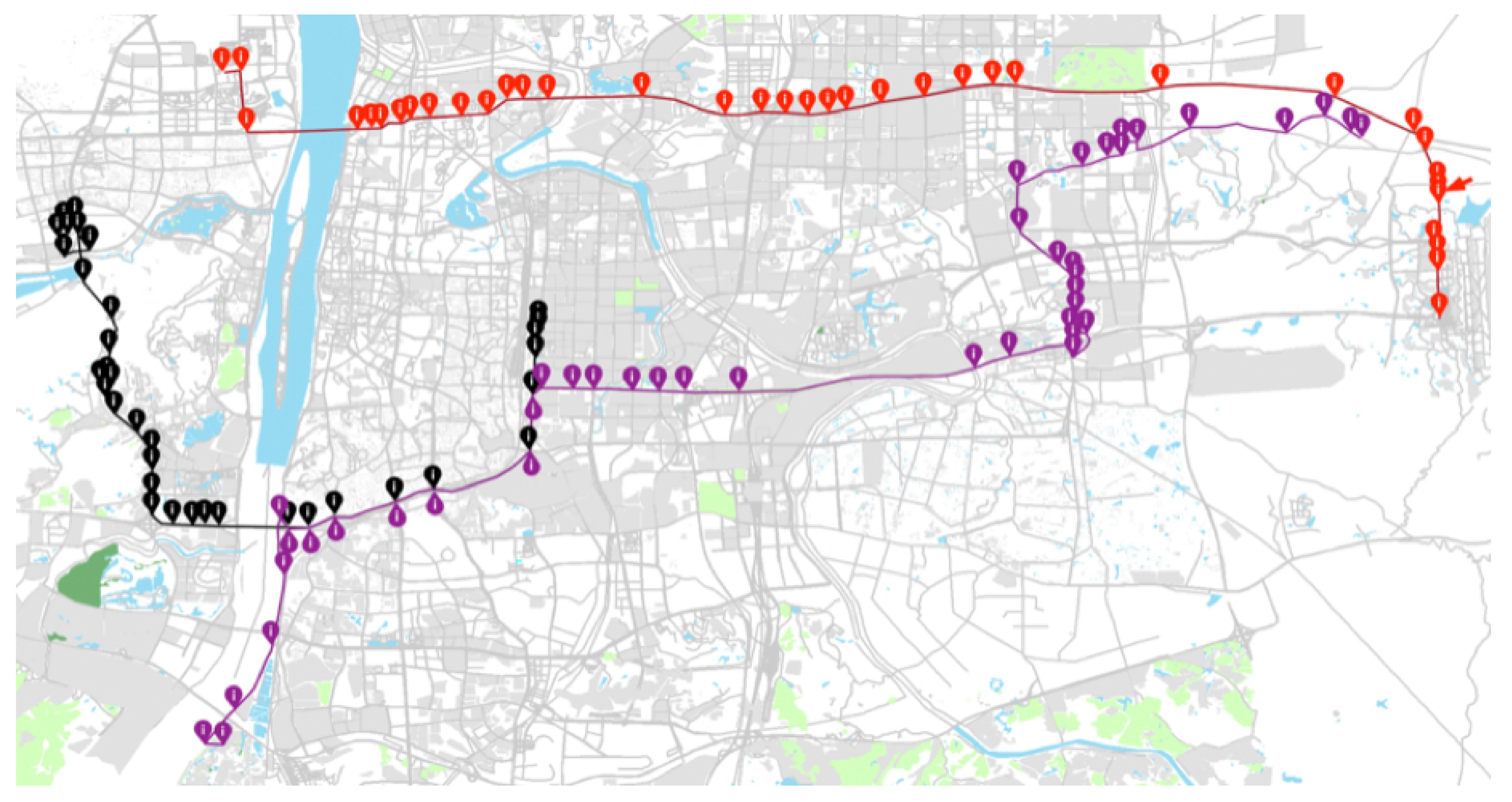
The trajectory dataset was collected by GPS recorders on floating cars. The movements captured in this dataset mainly took place in Changsha city, China on 1st January 2015. And the selected GPS trajectories were preprocessed based on following conditions: (1) the sampling rate ranged from 10 to 30 s; (2) the average horizontal dilution of precision (HDOP) was less than 1.25. The motivations for this kind of preprocess are manifold, ranging from eliminating outliers of trajectory data, to better reducing redundant sampling points. From the filtered trajectory dataset, only a total of 4 trajectories were selected from the original dataset (as shown in Figure 6). Although the sample size is not large, the subjects provide coverage of all types of trajectory-element intersections and are thus useful for our application example. Then a visual approach based on ArcGIS was applied to manually detect and mark trajectory-element intersections. Specifically, trajectory-element intersections inside road edges were carefully extracted.
Model Instantiation. The instantiation was conducted to illustrated the practicability of our proposed model on expressing topological semantics and performing deeper analyses with respect to motion happened in road network structures. Usually, this kind of application needs to study the movement of operating vehicles visiting different road segments—which can be further extended by introducing specific POIs nearby, such as buildings and parks.
As shown in Figure 7, the model was instantiated on a specific trajectory-element intersection (which is also marked by a red arrow in Figure 6). The intersection occurred about 10:50 at a specific position (i.e., the coordinates of its corresponding ). In fact, an intersection can also occur within a time period in which the runs behind the starTime. As one can see, from the corresponding tuple , that the is linked to , which means it took place in the interior of instead of a node. And it is not the end of the track for non-null sub-trajectories in both and . It is easy to see that the car moved along the edge before it reached the of this intersection and then left the road network space. The sub-trajectories within topological part can be further extended with other detailed semantics, such as “stop” and “move”, but in this example only topological semantics around the trajectory-element intersection are highlighted.
5.2. Semantic Trajectory Queries
In order to demonstrate applicability of the proposed model, several query examples are presented, which can be answered easier based on topological semantics. Generally, queries related to movements within a road network may vary as the users focus changes. If a user pays more attention to individual mobility, there may be queries such as “what time does an object enter (or leave) a road segment” and “which road dose an object locate in at specific time”. However, if a user focuses on group features, there may be queries like “extract the common path of several given trajectories”. In addition, queries can also be information about specific road segment like “are there cars that turned around inside the road segment ”. Note that these kinds of queries could not be easily answered by trajectory models without the context of the road network. In addition, the detailed foreign key joins in the query expressions are omitted, since the stress of this paper is the proposed conceptual model rather than the specific logical model and tables resulting from relationships.
Following are four typical examples that can be answered based on the proposed model.
Q1: Which road segments did the trajectory T1 travel through from 2015-01-01T09:30:00Z to 2015-01-01T10:00:00Z?
To answer this question temporal information of trajectory-element intersections within the trajectory T1 is necessary. Information about the trajectory identifier with the attribute tid = T1, the trajectory-element intersection with the attribute startTime between ‘2015-01-01 09:30:00’ and ‘2015-01-01 10:00:00’ and the attribute endTime between ‘2015-01-01 09:30:00’ and ‘2015-01-01 10:00:00’. The SQL statement could be as follows:
SELECT distinct ve.eid
FROM Trajectory-element Intersection ti JOIN TopologicalSemanticTrajectory tst,
  Trajectory-element Intersection ti JOIN TopologicalPartGroup tpg,
  TopologicalPartGroup tpg JOIN VirtualEdge ve
WHERE tst.tid = “T1” AND
  ti.startTime between ‘2015-01-01 09:30:00’ and ‘2015-01-01 10:00:00’ AND
  ti.endTime between ‘2015-01-01 09:30:00’ and ‘2015-01-01 10:00:00’
Another example could be that one would like to know which road segment a person had made a turn inside it. Therefore, the question could be:
Q2: Which road segments did the trajectory T1 turn around from 2015-01-01T09:00:00Z to 2015-01-01T10:30:00Z?
To answer this question the temporal and spatial information of trajectory-element intersections within the trajectory T1 would be used. Information about the trajectory identifier with the attribute tid = T1, the trajectory-element intersection with the attribute startTime between ‘2015-01-01 09:30:00’ and ‘2015-01-01 10:00:00’ and the attribute endTime between ‘2015-01-01 09:30:00’ and ‘2015-01-01 10:00:00’, and the SimpleBehavior with the attribute name = internal turning-through. The SQL statement could be as follows:
SELECT distinct kp.eid
FROM Trajectory-element Intersection ti JOIN TopologicalSemanticTrajectory tst,
  Trajectory-element Intersection ti JOIN TopologicalPartGroup tpg,
  Trajectory-element Intersection ti JOIN SimpleBehavior sb,
  TopologicalPartGroup tpg JOIN KeyPoint kp
WHERE tst.tid = “T1” AND
  ti.startTime ‘2015-01-01 09:30:00’ and ‘2015-01-01 10:00:00’ AND
  ti.endTime between ‘2015-01-01 09:30:00’ and ‘2015-01-01 10:00:00’ AND
  sb.name = “internal turning-around”
For the commercial vehicle application, it might be interesting to find routes or parts of routes locating outside of the existed road network. Actually, it is important to know these kinds of mismatches between trajectories and a road network structure, since researchers and staff can detect possible problem of road network data [37], such as a local topological connectivity error and a road segment deficiency, or even infer the potential demand for constructing a new road. For this kind of problem, the question could be:
Q3: Dose the trajectory T1 drive off the existing road?
To answer this question information related to topological parts within each trajectory-element intersection would be traversed. In our target topological part, like the (or ), the attribute eid = null and the attribute stid <> null. It is noted that there is a “UNION” process on result sets on both postEs and preES for completeness. The following SQL statement could answer this question:
SELECT pre.stid
FROM Trajectory-element Intersection ti JOIN TopologicalSemanticTrajectory tst,
  Trajectory-element Intersection ti JOIN TopologicalPartGroup tpg,
  TopologicalPartGroup tpg JOIN preEs pre
WHERE tst.tid = “T1” AND
  pre.eid = “null” AND
  pre.stid <> “null”
UNION
SELECT pte.stid
FROM Trajectory-element Intersection ti JOIN TopologicalSemanticTrajectory tst,
  Trajectory-element Intersection ti JOIN TopologicalPartGroup tpg,
  TopologicalPartGroup tpg JOIN preEs pre
WHERE tst.tid = “T1” AND
  pte.eid = “null” AND
  pte.stid <> “null”
For some researches it is import to figure out traffic conditions at some specific roads in a certain period of time. This is a significant change in intelligent traffic systems. Understanding traffic conditions and even patterns with road networks, we could better analyze the traffic and suggest the more proper routes for drivers under different conditions. For this kind of problem, the question could be:
Q4: Are there any trajectory had entered the Xiang-Fu Road between 2015-01-01T06:30:00Z and 2015-01-01T9:30:00Z?
To answer this question different semantic information related to trajectory-element intersections are necessary. The trajectory-element intersection with the attribute startTime between ‘2015-01-01 09:30:00’ and ‘2015-01-01 10:00:00’ and the attribute endTime between ‘2015-01-01 09:30:00’ and ‘2015-01-01 10:00:00’, the RoadNetworkElement with the attribute name = Xiang-Fu Road, and the SimpleBehavior with the attribute name = driving-through. The following SQL statement could answer this question:
SELECT tst.tid
FROM Trajectory-element Intersection ti JOIN TopologicalSemanticTrajectory tst,
  Trajectory-element Intersection ti JOIN TopologicalPartGroup tpg,
  Trajectory-element Intersection ti JOIN SimpleBehavior sb,
  TopologicalPartGroup tpg JOIN VirtualEdge ve,
  VirtualEdge ve JOIN RoadNetworkElement rne WHERE ti.startTime ‘2015-01-01 09:30:00’ and ‘2015-01-01 10:00:00’ AND
  ti.endTime between ‘2015-01-01 09:30:00’ and ‘2015-01-01 10:00:00’ AND
  rne.ename = “Xiang-Fu Road” AND
  sb.name = “driving-through”
For more complex questions, such as “do any group of trajectories share the same routes”, there was no direct answers by SQL statement with this model. It requires the user to employ data mining methods for analyzing. However, our semantic trajectory model makes it easier or user to apply data mining algorithms on trajectories. For example: (1) The common route of a group of trajectories can be captured by focusing on sequences of trajectory-element intersections instead of computation on GPS sampling points; (2) also, analyses related to the trajectory similarity can be made easier by turning to a comparison of sequences of trajectory-element intersections.
6. Conclusions
The importance of considering external environmental factors has been realized after a huge amount of research work on analyzing raw trajectories. To bridge the gap between raw trajectory data and contextual data, we need to research the trajectories in company with specific contexts. This is calling for trajectory analytical methods that can analyze the movement of objects (e.g., cars, pedestrians or animals) under certain space while presenting core features of a trajectory. Thus, we propose a model, namely TOST, going in the direction of associating trajectory data with one of the most common contexts, i.e., the road network, to make a raw trajectory meaningful.
We investigated the problem of modeling semantic trajectories inside road networks. Based on intersection-based topological semantic description, the proposed model is comparatively flexible for expressing movements inside road networks in a more meaningful way. The contribution of this paper has been: (1) to encapsulate raw GPS trajectory data in a semantically representation, and (2) to qualitatively express movements, by topological invariants, for direct support of trajectory semantics. Eventually, an instantiation of the model is shown. The work reported is, to the best of our knowledge, the first one to propose an approach for modeling semantics of moving objects from the perspective of topological characteristics.
We firmly believe that the proposed model TOST provides the basic concepts for semantic trajectories with road network space. It can serve as the baseline for researches on space-constrained semantic trajectories management and semantic trajectory knowledge discovery. Work is still needed to further study the interaction between our semantic trajectory model and the existing generic trajectory semantics that have been proposed in the literature. In a near future, we intend to investigate two related issues to explore trajectory movements based on the model TOST. The first one is to extend it to model the movement of one object against multi-scale elements. With such an extension, it is supposed to natively support more advanced analyses. The second point is to further analyze those sub-trajectories, especially to explore a more-refined sub-trajectory taxonomy.
Author Contributions
Conceptualization, Tao Wu; Investigation, Jianxin Qin; Methodology, Tao Wu; Writing—original draft, Tao Wu; Writing—review & editing, Yiliang Wan.
Funding
This work was supported by National Natural Science Foundation of China (Grant No. 41701465), Natural Resources Research Project of Department of Natural and Resources of Hunan Province (Grant No. 2019-20), Open Foundation of Key Laboratory for National Geographic State Monitoring of National Administration of Surveying, Mapping and Geoinformation (Grant No. 2016NGCMZD02).
Acknowledgments
The authors would like to thank the three anonymous reviewers for their valuable comments on the manuscript.
Conflicts of Interest
The authors declare no conflict of interest.
References
- Yan, Z.; Chakraborty, D.; Parent, C.; Spaccapietra, S.; Aberer, K. Semantic trajectories: Mobility Data Computation and Annotation. ACM Trans. Intell. Syst. Technol. 2013, 4, 1–38. [Google Scholar] [CrossRef]
- Issa, H. Spatio-textual trajectories: Models and Applications. Ph.D. Thesis, University of Milan, Milan, Italy, 2017. [Google Scholar]
- Spaccapietra, S.; Parent, C.; Damiani, M.L.; de Macedo, J.A.; Porto, F.; Vangenot, C. A Conceptual View on Trajectories. Data Knowl. Eng. 2008, 65, 126–146. [Google Scholar] [CrossRef]
- Damiani, M.L.; Guting, R.H.; Valdés, F.; Issa, H. Moving Objects Beyond Raw and Semantic Trajectories. Int. Workshop Inf. Manag. Mob. Appl. 2013. [Google Scholar] [CrossRef]
- Schmid, F.; Richer, K.F.; Laube, P. Semantic Trajectory Compression. Int. Symp. Spat. Temporal Databases 2009, 5644, 411–416. [Google Scholar] [CrossRef]
- Li, X.; Lin, H. Indexing network-constrained trajectories for connectivity-based queries. Int. J. Geogr. Inf. Sci. 2006, 20, 303–328. [Google Scholar] [CrossRef]
- Macedo, J.; Vangenot, C.; Othman, W.; Pelekis, N.; Frentzos, E.; Kuijpers, B.; Ntoutsi, I.; Spaccapietra, S.; Theodoridis, Y. Trajectory Data Models. In Mobility Data Mining and Privacy; Giannotti, F., Pedreschi, D., Eds.; Springer: Berlin, Germany, 2009; pp. 123–150. [Google Scholar]
- Khatri, V.; Ram, S.; Snodgrass, R.T. Augmenting a conceptual model with geospatiotemporal annotations. IEEE Trans. Knowl. Data Eng. 2004, 16, 1324–1338. [Google Scholar] [CrossRef]
- Tryfona, N.; Price, R.; Jensen, C.S. Conceptual Models for Spatio-temporal Applications. In Spatio-Temporal Databases; Springer: Berlin, Germany, 2003. [Google Scholar]
- Camossi, E.; Bertolotto, M.; Bertino, E.; Guerrini, G. A multigranular spatiotemporal data model. In Proceedings of the ACM International Symposium on Advances in Geographic Information Systems, New Orleans, LA, USA, 7–8 November 2003; pp. 94–101. [Google Scholar] [CrossRef]
- Pelekis, N.; Theodoridis, Y. An Oracle Data Cartridge for Moving Objects; CiteSeerX: University Park, PA, USA, 2007. [Google Scholar]
- Hajari, H.; Hakimpour, F. A Spatial Data Model for Moving Object Databases. Int. J. Database Manag. Syst. 2014, 6, 1–20. [Google Scholar] [CrossRef]
- Zheng, Y. Trajectory Data Mining. ACM Trans. Intell. Syst. Technol. 2015, 6, 1–41. [Google Scholar] [CrossRef]
- Bogorny, V.; Renso, C.; de Aquino, A.R.; de Lucca Siqueira, F.; Alvares, L.O. CONSTAnT-A Conceptual Data Model for Semantic Trajectories of Moving Objects. Trans. GIS 2013, 18, 66–88. [Google Scholar] [CrossRef]
- Damiani, M.L.; Güting, R.H. Semantic Trajectories and Beyond. In Proceedings of the IEEE 15th International Conference on Mobile Data Management, Brisbane, Australia, 14–18 July 2014. [Google Scholar]
- Spaccapietra, S.; Parent, C. Adding Meaning to Your Steps. In Proceedings of the International Conference on Conceptual Modeling, Brussels, Belgium, 31 October–3 November 2011; Volume 6998, pp. 13–31. [Google Scholar] [CrossRef]
- Yan, Z. Semantic Trajectories: Computing and Understanding Mobility Data. Ph.D. Thesis, Verlag nicht ermittelbar. 2011. [Google Scholar]
- Parent, C.; Spaccapietra, S.; Renso, C.; Andrienko, G.; Andrienko, N.; Bogorny, V.; Damiani, M.L. Semantic Trajectories Modeling and Analysis. ACM Comput. Surv. 2013, 45, 1–37. [Google Scholar] [CrossRef]
- Renso, C.; Baglioni, M.; de Macedo, J.A.F.; Trasarti, R.; Wachowicz, M. How you move reveals who you are: Understanding human behavior by analyzing trajectory data. Knowl. Inf. Syst. 2012, 37, 331–362. [Google Scholar] [CrossRef]
- Güting, R.H.; Valdés, F.; Damiani, M.L. Symbolic Trajectories. ACM Trans. Spat. Algorithms Syst. 2015, 1, 1–58. [Google Scholar] [CrossRef]
- Quddus, M.A.; Noland, R.B.; Ochieng, W.Y. The Effects of Navigation Sensors and Spatial Road Network Data Quality on the Performance of Map Matching Algorithms. Geoinformatica 2009, 13, 85–108. [Google Scholar] [CrossRef]
- Greenfeld, J. Matching GPS Observations to Locations on a Digital Map. In Proceedings of the Annual Meeting of the Transportation Research Board, Washington, DC, USA, 12–16 January 2002; pp. 164–173. [Google Scholar]
- Quddus, M.A. High Integrity Map Matching Algorithms for Advanced Transport Telematics Applications. Ph.D. Thesis, University of London, London, UK, 2006. [Google Scholar]
- Quddus, M.A.; Noland, R.B.; Ochieng, W.Y. A High Accuracy Fuzzy Logic Based Map Matching Algorithm for Road Transport. J. Intell. Transp. Syst. 2007, 10, 103–115. [Google Scholar] [CrossRef]
- Lou, Y.; Zhang, C.; Zheng, Y.; Xie, X.; Wang, W.; Huang, Y. Map-Matching for Low-Sampling-Rate GPS Trajectories. In Proceedings of the ACM SIGSPATIAL International Conference on Advances in Geographic Information Systems, San Jose, CA, USA, 2–5 November 2009; pp. 352–361. [Google Scholar] [CrossRef]
- Fileto, R.; Bogorny, V.; May, C.; Klein, D. Semantic Enrichment and Analysis of Movement Data: Probably it is just Starting! SIGSPATIAL Spec. 2015, 7, 11–18. [Google Scholar] [CrossRef]
- Wu, F.; Li, Z. Where did you go: Personalized annotation of mobility records. In Proceedings of the ACM 25th International on Conference on Information and Knowledge Management, Indianapolis, IN, USA, 24–28 October 2016; pp. 589–598. [Google Scholar] [CrossRef]
- Xiang, L.; Wu, T.; Ettema, D. An intersection-based trajectory-region movement study. Trans. GIS 2016, 21, 701–721. [Google Scholar] [CrossRef]
- Tiesyte, D.; Jensen, C.S. Similarity-Based Prediction of Travel Times for Vehicles Traveling on Known Routes. In Proceedings of the ACM SIGSPATIAL International Conference on Advances in Geographic Information Systems, Irvine, CA, USA, 5–7 November 2008. [Google Scholar] [CrossRef]
- Richter, K.F.; Schmid, F.; Laube, P. Semantic trajectory compression: Representing urban movement in a nutshell. J. Spat. Inf. Sci. 2012, 4, 3–30. [Google Scholar] [CrossRef]
- Li, Z. Semantic Understanding of Spatial Trajectories. Adv. Spat. Temporal Databases 2017, 10411, 398–401. [Google Scholar] [CrossRef]
- Spinsanti, L.; Celli, F.; Renso, C. Where You Stop is Who You are: Understanding People’s Activities by Places Visited. Behav. Monit. Interpret. 2010, 678. [Google Scholar]
- Schussler, N.; Axhausen, K.W. Processing Raw Data from Global Positioning Systems without Additional Information. Transp. Res. Rec. J. Transp. Res. Board 2009, 2105, 28–36. [Google Scholar] [CrossRef]
- Kuijpers, B.; Othman, W. Trajectory databases: Data models, uncertainty and complete query languages. J. Comput. Syst. Sci. 2010, 76, 538–560. [Google Scholar] [CrossRef] [Green Version]
- Pelekis, N.; Kopanakis, I.; Kotsifakos, E.E.; Frentzos, E.; Theodoridis, Y. Clustering uncertain trajectories. Knowl. Inf. Syst. 2011, 28, 117–147. [Google Scholar] [CrossRef]
- Openstreetmap. 2015. Available online: http://www.openstreetmap.org (accessed on 1 January 2015).
- Wu, T.; Xiang, L.; Gong, J. Updating Road Networks by Local Renewal from GPS Trajectories. ISPRS Int. J. Geo-Inf. 2016, 5, 163. [Google Scholar] [CrossRef]
Figure 1.
A conceptual data model for topological semantic trajectories inside road networks.

Figure 2.
Trajectory-element intersections during a topological semantic trajectory. (a) A trajectory divided be intersections; (b) three detailed trajectory-element intersections within a trajectory; (c) corresponding relations within a trajectory-element intersection.
Figure 2.
Trajectory-element intersections during a topological semantic trajectory. (a) A trajectory divided be intersections; (b) three detailed trajectory-element intersections within a trajectory; (c) corresponding relations within a trajectory-element intersection.

Figure 3.
Topological part groups of trajectory-element intersections. (a) Three typical topological part groups of trajectory-element intersections; (b) a topological part group at the starting point of the trajectory; (c) a topological part group at the ending point of the trajectory; (d) a topological part group at interval of the trajectory.

Figure 4.
Eight tuples and their trajectory-element intersections. White dots denote nodes, red dots denote keyPoints and arrows denote movement directions. (a) Two initial intersections moving inside the network; (b) two initial intersections moving outward the network; (c) two terminal intersections moving inside the network; (d) two terminal intersections moving from outside of the network; (e) three basic intersections moving inside the network; (f) two basic intersections outward the network; (g) two basic intersections moving from outside of the network; (h) two basic intersections moving across the network.

Figure 5.
Two real trajectories within the road network. (a) Images of the two trajectory; (b) intersections sequences of the student’s trajectory; (c) intersections sequences of the teacher’s trajectory.
Figure 5.
Two real trajectories within the road network. (a) Images of the two trajectory; (b) intersections sequences of the student’s trajectory; (c) intersections sequences of the teacher’s trajectory.

Figure 6.
The image of four trajectories in Changsha (background obtained from OpenStreetMap (OSM)).
Figure 6.
The image of four trajectories in Changsha (background obtained from OpenStreetMap (OSM)).

Figure 7.
The instantiation for a commercial vehicle trajectory.


Table 1.
Seventeen situations for trajectory-element intersections.
| Pattern | Tuple initiation | Situation |
|---|---|---|
| start from a node and enter into an edge | ||
| start from an edge and move along it | ||
| start from a node and go off roads | ||
| start from an edge and go off roads | ||
| move along an edge and end at the next node | ||
| move along an edge and end at it | ||
| move into a node from outside of network and end at it | ||
| move into an edge from outside of network and end at it | ||
| move into the from by a node | ||
| move along an edge and turn back after reaching a node | ||
| move along an edge and turn back at a position inside the edge | ||
| move along an edge and leave road network space at a node | ||
| move along an edge and leave road network space at position inside the edge | ||
| move into an edge from outside of network at a node and move along the edge | ||
| move into an edge from outside of network at a position inside the edge and move along it | ||
| pass a node without entering other elements | ||
| pass a position inside an edge without entering other elements |
© 2019 by the authors. Licensee MDPI, Basel, Switzerland. This article is an open access article distributed under the terms and conditions of the Creative Commons Attribution (CC BY) license (http://creativecommons.org/licenses/by/4.0/).
Share and Cite
MDPI and ACS Style
Wu, T.; Qin, J.; Wan, Y. TOST: A Topological Semantic Model for GPS Trajectories Inside Road Networks. ISPRS Int. J. Geo-Inf. 2019, 8, 410. https://0-doi-org.brum.beds.ac.uk/10.3390/ijgi8090410
AMA Style
Wu T, Qin J, Wan Y. TOST: A Topological Semantic Model for GPS Trajectories Inside Road Networks. ISPRS International Journal of Geo-Information. 2019; 8(9):410. https://0-doi-org.brum.beds.ac.uk/10.3390/ijgi8090410
Chicago/Turabian StyleWu, Tao, Jianxin Qin, and Yiliang Wan. 2019. "TOST: A Topological Semantic Model for GPS Trajectories Inside Road Networks" ISPRS International Journal of Geo-Information 8, no. 9: 410. https://0-doi-org.brum.beds.ac.uk/10.3390/ijgi8090410
Note that from the first issue of 2016, this journal uses article numbers instead of page numbers. See further details here.