3D Geometry-Based Indoor Network Extraction for Navigation Applications Using SFCGAL


University of Ljubljana, Faculty of Civil and Geodetic Engineering, Department of Geodesy, SI-1000 Ljubljana, Slovenia
*
Author to whom correspondence should be addressed.
ISPRS Int. J. Geo-Inf. 2020, 9(7), 417; https://0-doi-org.brum.beds.ac.uk/10.3390/ijgi9070417
Submission received: 29 May 2020
/
Revised: 18 June 2020
/
Accepted: 27 June 2020
/
Published: 29 June 2020
(This article belongs to the Special Issue 3D Indoor Mapping and Modelling)
Abstract
:This study is focused on indoor navigation network extraction for navigation applications based on available 3D building data and using SFCGAL library, e.g. simple features computational geometry algorithms library. In this study, special attention is given to 3D cadastre and BIM (building information modelling) datasets, which have been used as data sources for 3D geometric indoor modelling. SFCGAL 3D functions are used for the extraction of an indoor network, which has been modelled in the form of indoor connectivity graphs based on 3D geometries of indoor features. The extraction is performed by the integration of extract transform load (ETL) software and the spatial database to support multiple data sources and provide access to SFCGAL functions. With this integrated approach, the current lack of straightforward software support for complex 3D spatial analyses is addressed. Based on the developed methodology, we perform and discuss the extraction of an indoor navigation network from 3D cadastral and BIM data. The efficiency and performance of the network analyses were evaluated using the processing and query execution times. The results show that the proposed methodology for geometry-based navigation network extraction of buildings is efficient and can be used with various types of 3D geometric indoor data.
1. Introduction
The 3D geospatial data domain with its derived 3D geospatial information and applications is experiencing rapid development in all its aspects, including 3D spatial data acquisition, spatial data modelling and processing, spatial analysis and visualization [1,2,3,4]. 3D geospatial data and 3D geoinformation applications have gained momentum in the past decade as a rapidly developing geospatial industry with new sensors and platforms, as well as the rapid progress of information and communication technology, opened up possibilities for acquiring, collecting, modelling and analysing big geospatial datasets. However, 3D spatial data management and analyses together with all aspects of indoor spatial data had been lagging behind until recently [5]. The spatial data queries and analyses for decision making and indoor applications require advanced data models with high-quality geometry and topology. While many publications deal with geometrical and topological approaches to 3D geospatial modelling [6,7,8], integrating and managing 3D geospatial data on both the geometrical and semantic levels remains a big challenge and is the focus of several research activities [9,10,11]. The importance of 3D spatial data integration and management lies in the fact that many spatial analyses that produce valuable information use data from various sources, which need to be harmonized and integrated. The current software support for 3D spatial data analysis is inadequate, as most algorithms support only 2D spatial data processing and analyses. The demand for and importance of indoor spatial information are rapidly growing, creating a need to integrate the data from different domains [2,12,13]. The extraction and modelling of data and information relevant for indoor navigation from various data sources has been intensively studied in recent years [14,15,16,17,18]. The main aim of this study is to develop a methodology to perform the extraction of an indoor navigation network based solely on 3D geometry using SFCGAL functions, and to discuss the issues and advantages in using this approach. The methodology is applied to two different indoor spatial data sources, i. e. 3D cadastre data and BIM data, which are well-known 3D geometric and attribute data sources for building interiors.
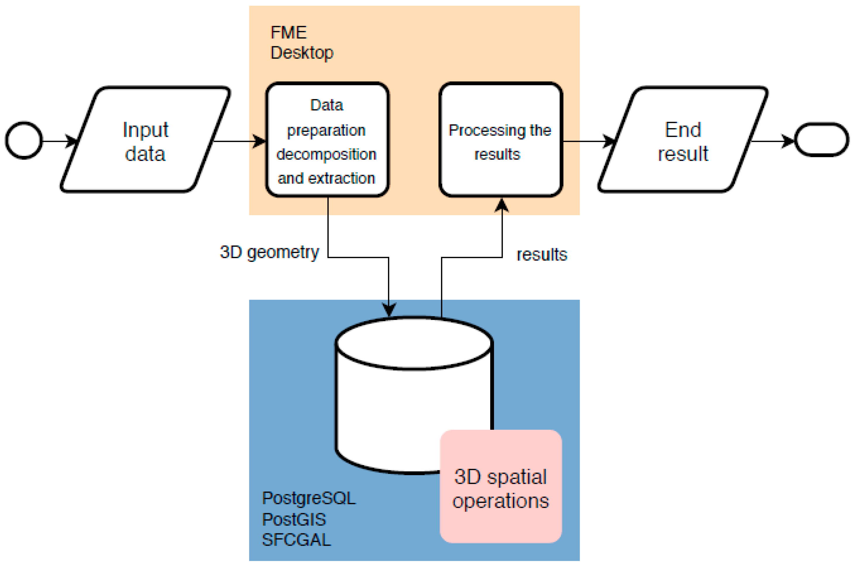
In the first part of the paper, the integration of spatial extract transform load (ETL) software [19] and the spatial database used to develop the methodology for geometry-based indoor navigation network extraction are presented. It is implemented using FME Desktop (FME) and PostgreSQL with PostGIS and SFCGAL [20] extensions. Assuming the ETL software supports the handling of 3D geometry, it can be effectively used for 3D geospatial data decomposition, integration, and data extraction, which is an important part of complex 3D spatial modelling and analyses. FME has strong support for 3D geospatial data manipulation and recently adopted standard data file formats such as CityGML [21], IndoorGML [22] and IFC (industry foundation classes) [23], together with other 3D data file formats (OBJ, COLLADA, STL, FBX, 3DS, and X3D). However, FME has some, though very limited, functionalities for processing 3D geometries. For this, the PostgreSQL database was selected as it provides access to SFCGAL 3D functions that enable processing of 3D geometries. The SFCGAL is a C++ wrapper library that supports ISO 19107:2013, and OGC (Open Geospatial Consortium) Simple Features Access 1.2 for 3D operations. The library is built around CGAL (Computational Geometry Algorithms Library), which provides algorithms for geometric computation. Besides the common spatial feature types, the PostGIS and SFCGAL enabled database supports storage of TINs (triangular irregular networks), polyhedral surfaces and solids, and offers functions to perform 3D spatial operations using the stored 3D geometries. As ETL software is designed to work with databases, it is common for ETL processes to include the databases. Our approach is different, as it uses the database for the access to 3D functions needed for extraction of an indoor navigation network based on 3D geometries.
The 3D cadastral case study aims to strengthen the idea of a multipurpose 3D cadastre. It builds on the 3D cadastral data model discussed in [24] with the difference that the solid geometries touch only at passages (e.g., doors). 3D geospatial data are to be used within a 3D cadastre to efficiently model the complex divisions of real property units in a 3D environment to which rights, restrictions and responsibilities are related [25]. Indoor navigation applications have generally been beyond the scope of traditional land administration, i.e., a cadastre. However, developments in 3D spatial data acquisition, management and visualization, especially in the last decade, have brought these two fields much closer [26]. Using cadastral data has some advantages over other data sources as the data is official, follows a predefined data model, and its quality is (or should be) controlled. The biggest current disadvantage is that the digital 3D cadastral systems are not yet introduced operationally at a larger scale.
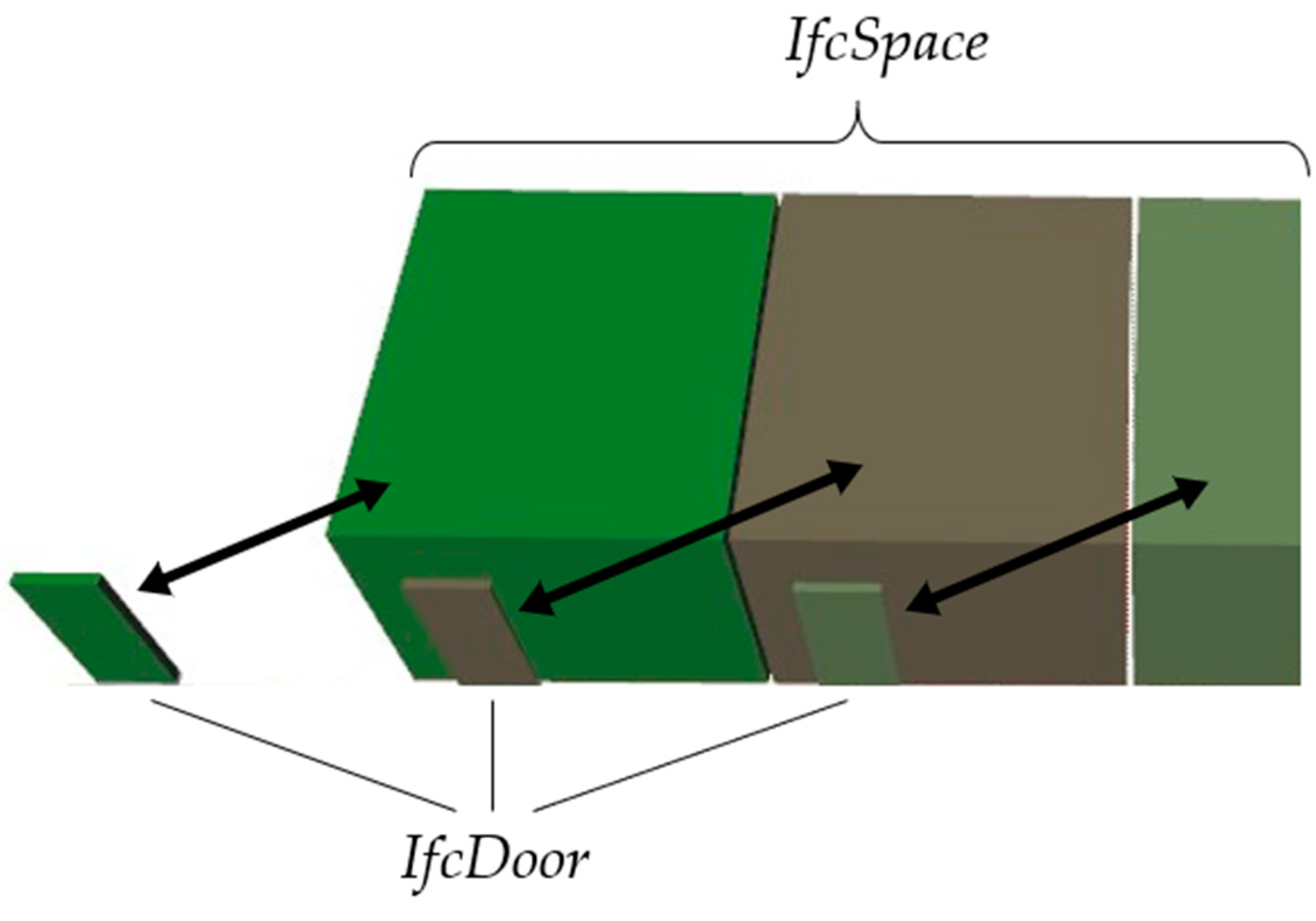
The BIM data meeting IFC standards (ISO 16739-1:2018) represent a rich data source for many building-related applications, including indoor navigation. Diakité and Zlatanova [12] and Lin et al. [27] have already considered IFC data as a data source for indoor navigation applications. Xu et al. [28] and Lin et al. [17] propose reducing the problem to 2D space and rasterization of vector geometry. Xiong et al. [14] used voxelization to avoid complex vector processing tasks. A voxel model was also used by Staats et al. [29]. Teo and Cho [30] and Khan et al. [31] use semantic information (IfcRelSpaceBoundary) in IFC files for navigation network extraction. In contrast, our study is focused on the extraction of a navigation network based solely on the 3D geometry of IfcSpace, IfcDoor and IfcStair entities. Our approach is comparable to the approaches that propose the semantic-based extraction of a navigation network from an IFC file [30,31].
2. Methodology
The study focuses on the processing of 3D geometric data for extraction of an indoor navigation network. The 3D geometries that are used in this context are navigable 3D indoor spaces. To perform the 3D operations and to derive the navigation network from input data, we integrate the FME spatial ETL software and PostgreSQL database with PostGIS and SFCGAL extensions (Figure 1).
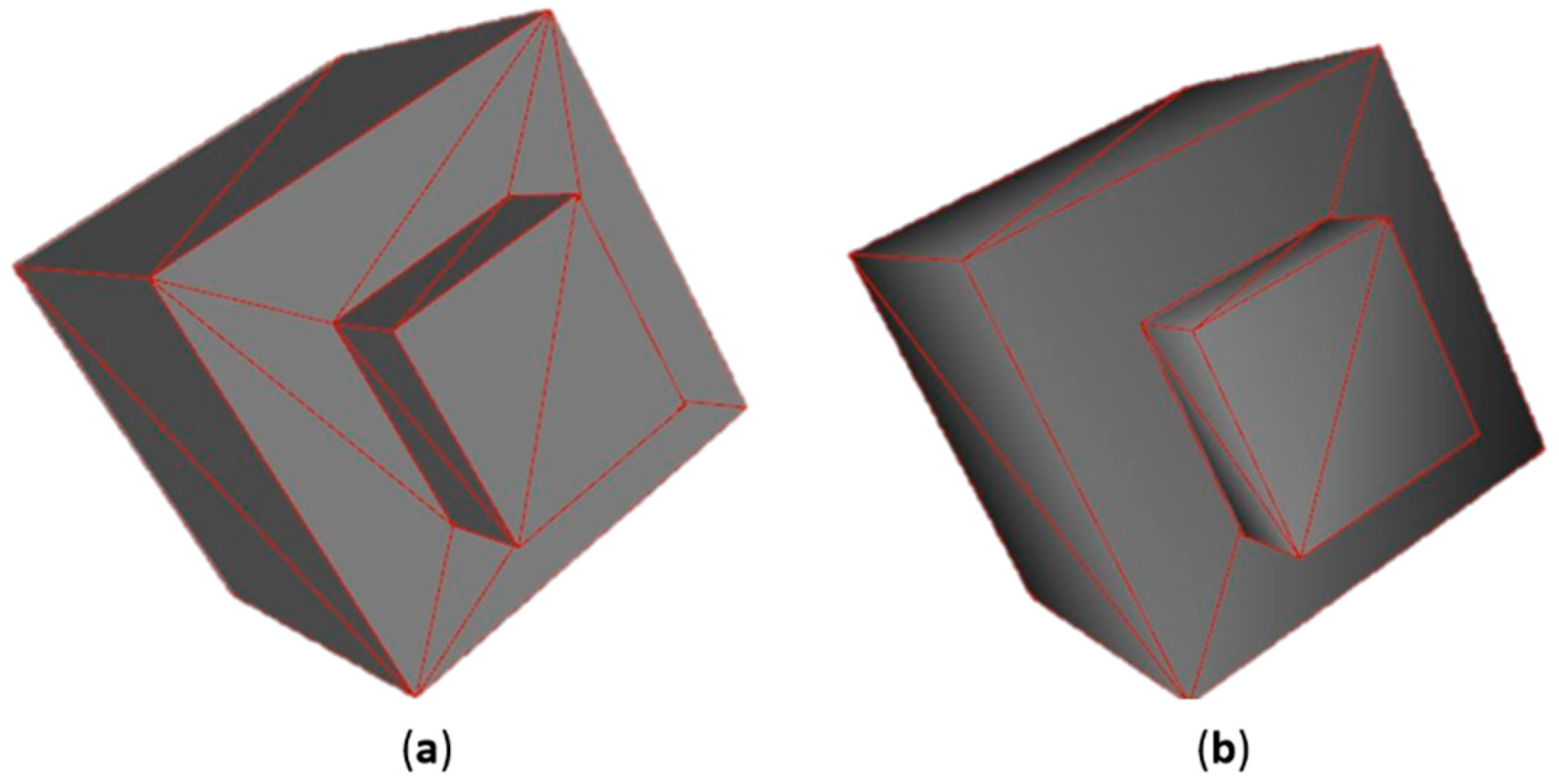
Before the data is transferred into the database, it should be pre-processed. The aim is to extract 3D geometries and attributes from input data and transform them into a form that can be imported into the PostGIS database and analysed with SFCGAL functions. Firstly, all the relevant entities that represent 3D geometries of indoor features have to be extracted from input data. Some input datasets (for instance IFC files) have to be decomposed into separate entities first. The decomposition and extraction of relevant data can be performed during the import of the dataset into FME. After that, various attribute or geometry filters can also be applied to select the relevant data for 3D processing with SFCGAL functions. In this phase, depending on the data source, the geometries can be validated using FME tools and, to some degree, corrected for errors. The data storage usually terminates the ETL process. In this case, the data writing into the PostGIS database is performed during the process, allowing it to be continued after the data is loaded. The greatest attention in this phase should be given to the geometry, as only PostGIS-supported geometry types can be inserted into the database. In this paper, the focus is on 3D solid geometries that are bounded by polyhedral surfaces. The bounding surfaces of the geometries can be obtained in FME by deaggregation of input geometries. When the input geometries are deaggregated (split into parts), it is important to preserve their unique attributes. These attributes are used to group the surfaces that bound each solid geometry when creating solid geometries. Due to different tolerances and definitions of solid geometries in FME and PostGIS, some of the geometries can be reported as invalid in PostGIS. Figure 2 shows an example of a valid 3D solid in FME (no solid validation errors reported) (a) before and (b) after insertion into PostGIS database. In this case, the bounding surfaces in PostGIS are not the same as in FME. This happens with the surfaces that have internal holes. Such geometries are reported by PostGIS as invalid. PostGIS also reports the validity error, when the points of the same surface do not lie on the same plane. Such geometries do not allow the use of SFCGAL 3D functions in the PostGIS database. The generic solution for this issue is to perform the triangulation of all surfaces in FME before creating solid geometries. This additional step makes all bounding surfaces of solids triangles. With triangles, we avoid the validity issues as they do not have internal holes and also cannot have points not lying on the same plane.
It should be noted that the triangulation changes the structure of the bounding surfaces, but this is not an issue for the presented application for geometry-based navigation network extraction. The geometries should be imported into the database together with identifiers to enable referencing the results of 3D operations in FME for later processing and writing of the results.
When the geometries (geom), identifiers (sn) and optional additional attributes are imported into the database (temporary table spaces), the SQL queries using SFCGAL 3D functions can be executed to derive the topological relationships of the inserted geometries. Generally, the navigable spaces that are in a touching relationship allow the transition from one to another. Some data models also allow the overlapping of navigable spaces that allow the transition. Here, we presume that the navigable spaces that are spatially disjoint do not allow the transition from one to another. Depending on the required complexity of the network, various methods can be used.
The first and most basic method uses the FME centroid placement tool and the SFCGAL ST_3DIntersects Boolean function to identify the pairs of geometries that intersect. The function returns TRUE for both overlapping and touching geometries. Using the query (Appendix A.1), we select two symmetrical pairs of identifiers (as start and end) per each connection of spaces that are found. If we want only one of the two pairs, the a.sn! = b.sn condition should be changed to a.sn > b.sn. The query results in the identifiers of the connected spaces. Parallel to query execution in the database, the 3D solid geometries are transformed to graph nodes using the FME centroid placement tool. The algorithm has an option to force the placement of the centroid inside the polygon, thus solving the issue of the external centroid for complex polygons (concave and doughnut polygons). As only 2D polygons are supported, each 3D solid geometry is converted to a 2D polygon representing an outline of each solid in the horizontal plane. Each node is vertically placed in the middle between the vertical bounds of the corresponding solid. The final navigation network is realized by joining the nodes to the result of the SQL query and creating the lines between connected nodes. The first approach results in a basic navigation network, also known as node-relation structure (NRS) [32], with connections that do not represent the path between the nodes (Figure 3). Consequently, such a network can be used for basic navigation applications without an option for visualization of the path. Boguslawski et al. [33] and Liu and Zlatanova [34] use this type of network as the basis for derivation of more complex navigable networks.
The second method provides enrichment of the original NRS to node-relation structure and entrance (NRSE) [32]. To perform this using SFCGAL, the ST_3DIntersection function is introduced, which outputs the geometry of the intersection (Appendix A.2). Using the intersection geometries and FME centroid placing tool, the additional nodes, placed at space connections, can be derived and added to the navigation network (Figure 4).
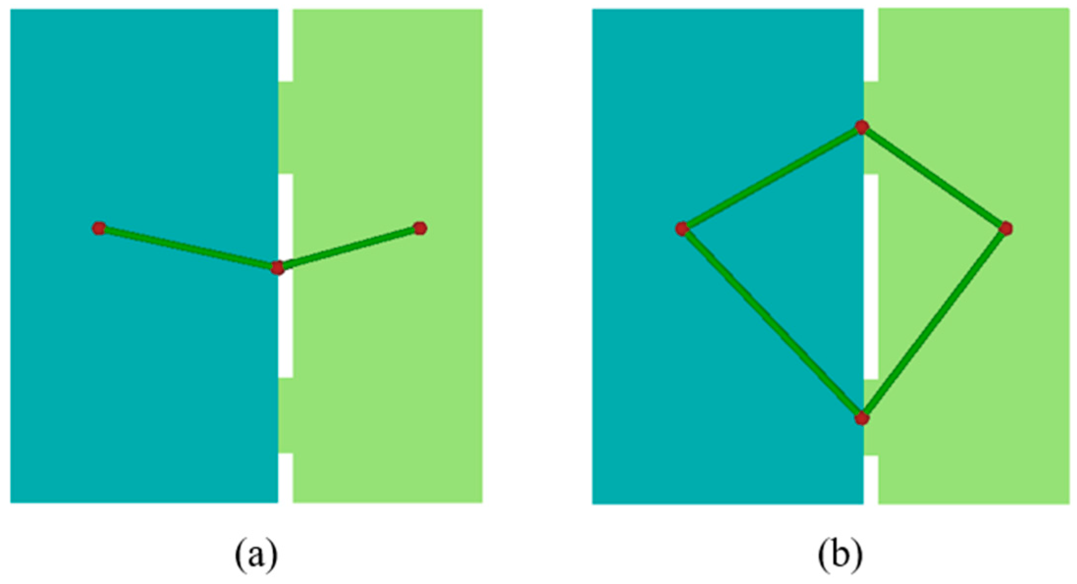
The method works for spaces that have only one connection to each connected space (Figure 4). Figure 5a shows an example of two spaces that are connected with multiple passages. Therefore, the method for NRSE derivation has to be modified to accommodate such cases. In these cases, the ST_3DIntersection function returns multiple intersection geometries as one feature. The FME deaggregator tool was used to split the spatially disjoint intersection geometries and thus place a node to each connection (Figure 5b).
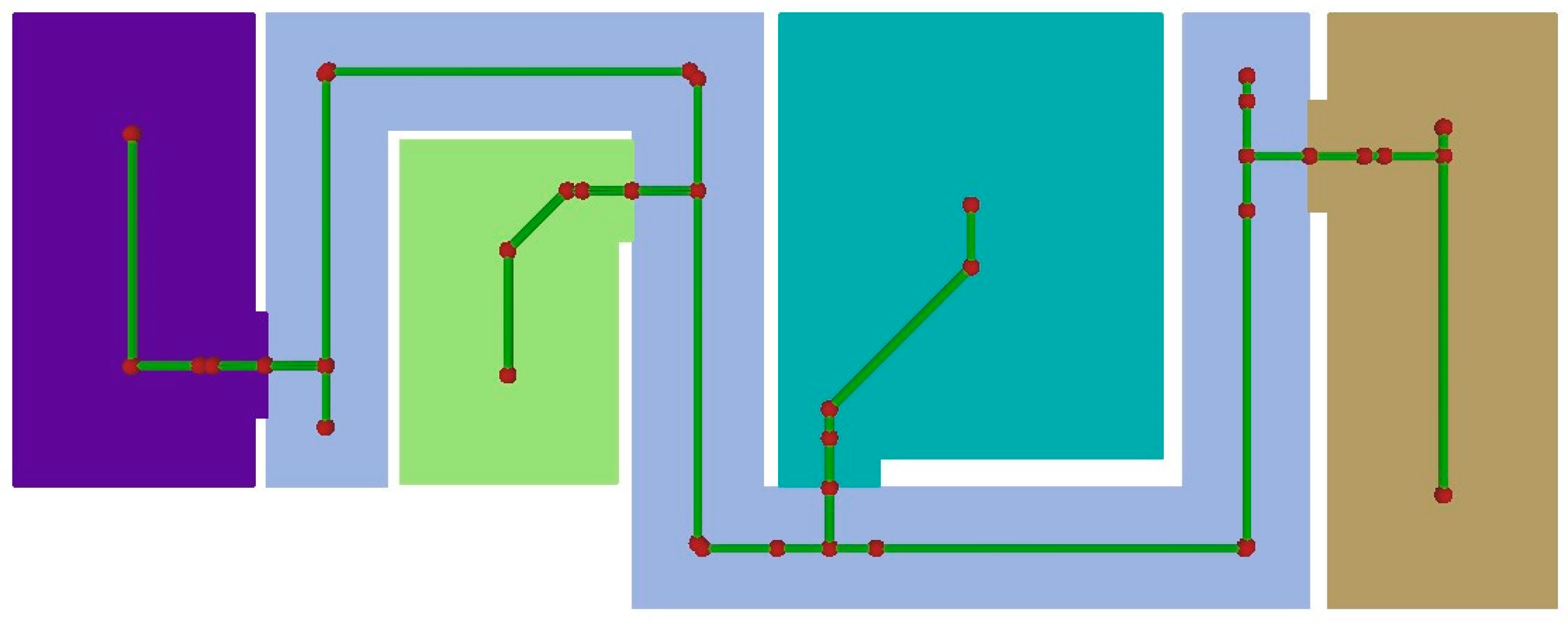
As shown in Figure 3 and Figure 4, the complexity of indoor spaces requires more advanced approaches that increase the number of nodes and optimize their placement. Many studies proposed various methods to derive the navigation network for optimal path planning. Most of them use methods that include medial axis transformation [30,32,35], structure segmentation using triangulated irregular networks (TINs) [18,33]. The SFCGAL function ST_ApproximateMedialAxis is used in the third proposed method that densifies the navigation network inside each space. As the function works only on 2D geometries, the solid geometries are transformed to their 2D outlines in FME and inserted into the PostGIS database (temporary table spaces2d) as polygons (geom) together with the identifiers of spaces (sn). There, the approximate medial axis is calculated for each polygon, obtaining the network edges (Appendix A.3). The ST_Dump function is used to derive the nodes of the calculated edges (Appendix A.4). At this stage, the calculated networks are not connected. The connection nodes of spaces are derived according to the second method and inserted into the PostGIS database (temporary table connections) with unique identifier (id) geometry (geom) and identifiers of both connected spaces (start, end). After joining the calculated edges (the result of the Appendix A.3 query) to the connections table, the nearest point on edge can be found using ST_ClosestPoint function that is included in standard PostGIS functions (Appendix A.5). This enables the connection of individual navigation networks into the final navigation network (Figure 6).
3. Results
3.1. Navigation Network from 3D Cadastral Data
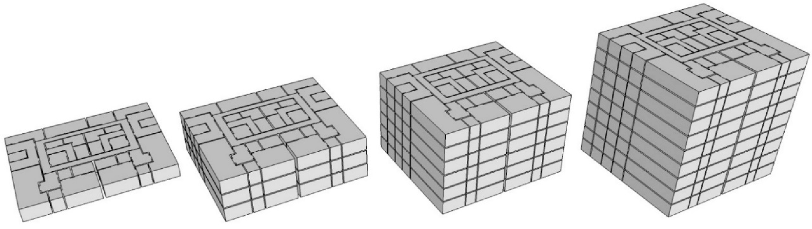
For the 3D cadastral case study, the input data is focused on buildings and can be characterized as a 3D version of traditional 2D floor plans used for condominium registration. The scope of the selected dataset used in the case study is limited to cadastral data, which is focused on the representation of the legal situation (e.g., real property units) using indoor spaces as a core spatial unit, defined by the physical structure of the building. Referencing the legal situation to the building’s physical structure for condominium or strata title registration using 2D floor plans is known in many countries worldwide. The 3D indoor spaces, modelled with solid geometries, represent the core of the test data model that has also been discussed in [24]. As the focus of the case study was on testing the performance of the developed methods, four generic 3D cadastral datasets were used, consisting of one, three, six and nine storeys with the same horizontal layout and one vertical connection per floor (Figure 7). The test datasets were modelled using SketchUp 3D modelling software. The connections between indoor spaces (e.g., doors) are materialized by shared surfaces which enable extraction of the topology information using the SFCGAL 3D geometry functions. The real property units can be derived by aggregation of the corresponding spaces, i.e., spatial units. It is possible to apply the proposed methods to any other 3D cadastral dataset if the data format is supported by the FME and if it follows the same data modelling principle, having 3D geometries of indoor spaces in touching relationships. The approach for modelling such datasets from existing 2D documentation, which can be found in many countries worldwide, has been proposed in [24].
All the test datasets were processed with all three presented methods in order to assess the performance of each method and the SQL queries included in each method. The processing times are used as results. While they enable relative comparisons, they depend heavily on the hardware that is used for processing. All the tests were performed on a PC equipped with i7-8565U CPU, 16 GB RAM and an SSD hard drive. Table 1 summarizes the processing results for the first and second method. Table 2 summarizes the results for the third method. For each method, a complete processing time is given, including all processes in FME and PostGIS. Additionally, the query execution times are given for each query that is included in the method. The processing times for Query Appendix A.2 in Table 2 are repeated from Table 1, as both the query and the data are identical for both methods Appendix A.
3.2. Navigation Network from IFC Data
The second case study is based on the example project IFC file from BIMcollab [36] for the office type building (Figure 8). Since many versions of IFC models exist, it should be emphasized that our method can be successfully applied only to the models that contain the IfcSpace, IfcDoor and IfcStair entities.
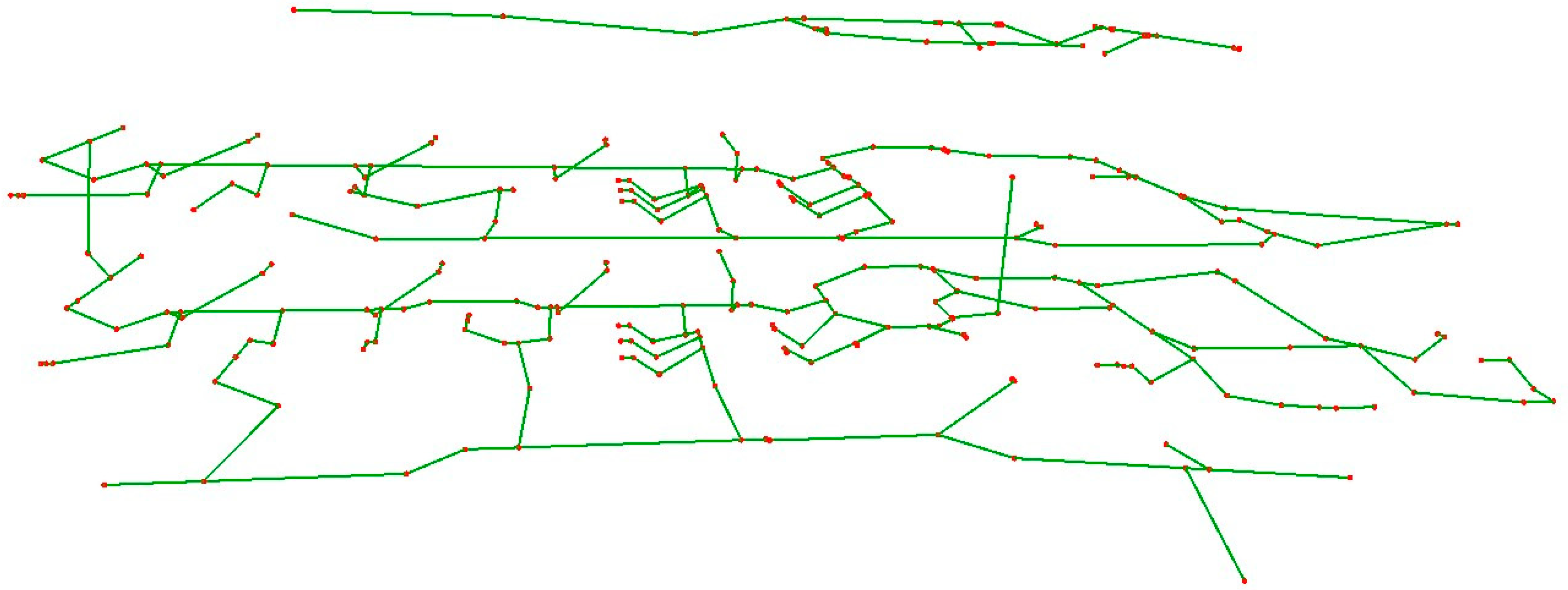
The input IFC file was imported and decomposed in FME, allowing the selection of individual IFC entities. First, we limited the selection of entities to IfcSpace, IfcDoor. We filtered the geometries by the type of geometry, where only solid geometries were passed through. Another filter passes only door solids with Name attribute value “Box” and space solids with Name attribute value “Body”. For doors, the Box geometry representation was selected due to complex Body geometry representation. The geometries of doors and spaces were inserted into the PostGIS database (tables spaces and doors), where a query (Appendix A.6) was executed, selecting the doors and spaces that intersect in 3D space. This process is aligned with our first method (using only the ST_3DIntersects function), but gives results similar to the second method (NRSE), as doors are included as spaces. This approach can be used to extract a navigation network for one floor as it lacks vertical connections that are modelled with IfcStair entities. To add them, we select IfcStair solid geometries with Name attribute value “Box” and insert them into the database (table stairs). The union of three queries (Appendix A.7) selects pairs of intersecting doors and spaces, pairs of intersecting spaces and stairs, and pairs of intersecting stairs. Figure 9 shows the navigation network derived from the result of these queries. The result contains the connections between all features that are in an intersecting relationship. Some doors intersect with spaces that are on a different floor, resulting in non-existent vertical connections between spaces (blue lines in Figure 9). To avoid the extraction of these connections, the query Appendix A.7 was replaced with three separate queries (Appendix A.8) with one using the ST_3Dintersection function that outputs the geometry of the intersection. The non-existent connections were filtered in FME using the vertical extent of the intersection geometries.
Secondly, we applied the third proposed method that uses the SFCGAL function ST_ApproximateMedialAxis to densify the navigation network and make it suitable for path planning applications. Figure 10 shows the navigation network obtained by applying the third method.
Table 3 summarizes the results of processing the test IFC file that contains 51 IfcSpace, 58 IfcDoor and 3 IfcStair entities. The first method that generated the NRSE network structure was implemented using Appendix A.6, Appendix A.7 and Appendix A.8 queries, while the third method was implemented using the Appendix A.8 queries, together with queries Appendix A.3, Appendix A.4 and Appendix A.5 for calculating the approximate medial axes and finding the closest connection points on them.
4. Discussion
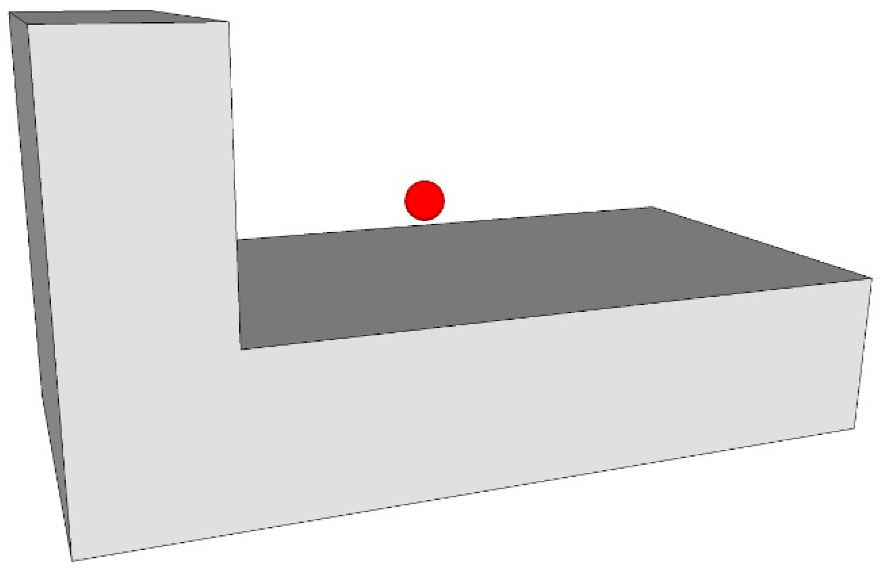
The proposed methods for indoor navigation network extraction use advanced SFCGAL functions that process the geometries in 3D. This enables us to work fully automatically with 3D data, depending only on geometry. In 2D, a similar approach can be used, but it requires the building to be divided into floors to avoid vertical overlap of features, which cannot be properly handled by 2D algorithms. The division depends on semantic information in building models or must be done manually. There is also the problem of assembling all processed floors into one vertically connected model. However, in some parts of the process, we also have to use 2D geometries. The first case is the centroid placement, and the second is the calculation of the approximate medial axis. Both processes are used to calculate the placement of the navigation network nodes. Before the transformation of geometries to 2D, their vertical bounds are calculated to enable 3D placement of the calculated nodes. We avoid the external centroids in 2D with the option in FME that guarantees the point to be inside the 2D polygon. The nodes are placed in 3D using the middle value of the vertical bounds of space geometries. In some cases, where the geometries of the spaces are more complex, the nodes can be placed outside of the 3D geometry of the space (Figure 11).
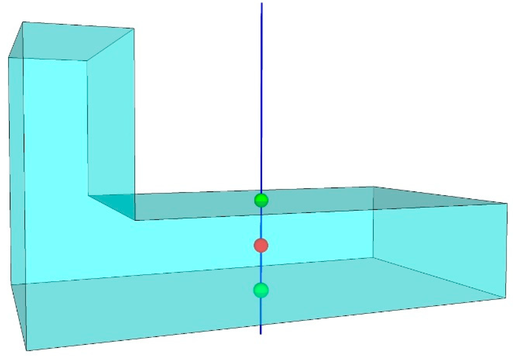
These errors can be found with additional processing in PostGIS. The nodes have to be inserted into PostGIS, where we can find the identifiers of solid geometries, which do not contain the corresponding node using the SQL query (Appendix A.9). The query uses the computationally demanding ST_3DIntersection function. The reason is that the ST_3DIntersects function does not work properly when comparing solid geometry and point geometry. Instead, the ST_3DIntersection function is used to check if the intersection geometry is empty, meaning the node is outside the corresponding solid geometry. Another option that avoids the presented errors is to create a vertical line for each node and intersect it with the space geometry (Figure 12) using an SQL query (Appendix A.10). The line is placed on the node location and has a larger vertical extent than the space geometry. The node that is inside the space geometry (red point) is between the calculated intersections (green points). Due to the usage of ST_3DIntersection function, both approaches significantly reduce the performance of the proposed methods, especially of the third method, where many network nodes are created for each space. Additional research is needed to improve the performance of the presented approaches for node placing inside 3D geometries.
The results of the first case study (Table 1 and Table 2) show the best performance of the first method, which produces the most basic results. However, the results of the first method can be used as input for more advanced indoor navigation network extraction methods [33]. While the time share of SQL query Appendix A.1 execution time is low for the first method, the execution time of the SQL query Appendix A.2 represents the majority of the processing time of methods 2 and 3. This is caused by the SFCGAL ST_3DIntersection function being computationally much more demanding than the SFCGAL ST_3DIntersects function. The FME processing time remains roughly the same for all methods and increases linearly with the increase in the number of processed spaces. The difference in processing time for methods 2 and 3 is minimal as the query Appendix A.2 is the same for both methods. Additional queries in method 3 that calculate the approximate medial axes and their connections are basically non-significant in terms of execution time as they are all executed in less than 0.6 s for all cases. The 3D cadastral data model that is used in this case study has an additional advantage when it is processed using 3D functions. The intersection geometry calculated in methods 2 and 3 using ST_3DIntersection function is a surface. The SFCGAL function ST_3DArea can be used to calculate the area of an intersection to check if the passage is navigable for a particular locomotion type.
The results of the second case study (Table 3) prove that the proposed methods can be efficiently applied to IFC data if it contains the required entities (IfcSpace, IfcDoor and IfcStair). Since the IFC data model is standardized, any other IFC dataset that contains these entities can be processed the same way as the test dataset. Method 2 was not used in this case study as it aims to extract nodes at the connections of spaces (where they touch) and the IfcSpace geometries do not touch each other. In combination with IfcDoor geometries, method 1 produces similar results as method 2 in the first case study. The query A8 reduces the errors in the navigation network, but it requires the use of the ST_3DIntersection function, which significantly reduces the query performance.
In the cadastral data model, the stair spaces were modelled the same way as other spaces, which is not the case for the IFC data model. If the stairs are located inside the building, our approach successfully derived the vertical connections. Some IfcStair entities in the test dataset have no geometric contact with other IfcStair entities or any of the IfcDoor and IfcSpace entities, which caused some vertical connections to be left out. This can be seen in the upper part of Figure 9 and Figure 10, where a part of the navigation network is not connected to the rest of the network. This represents a disadvantage of the geometry-based methods, as there is no option to extract the connection if the geometries of the features are spatially disjoint. In these cases, the methods that are based on semantic information have the advantage. We compared our approach to the semantic-based approaches [30,31], which use the IfcRelSpaceBoundary entities to extract the navigation network from IFC dataset. The comparison can be done only for the IFC models, that also contain the IfcRelSpaceBoundary entity. We joined the RelatingSpace attribute from the IfcRelSpaceBoundary entity to IfcDoor, thus getting information about IfcDoor and IfcSpace relations that were used to derive the navigation network. The process was very fast, as the connections were found based on the attributes. However, we found that the IfcRelSpaceBoundary entities contain errors, which caused some wrong connections between spaces and doors, shown in Figure 13. It should be noted that the files available in 2020 were altered and corrected for these errors.
The results of the case studies show that the quality of the extracted navigation network depends on several factors. The first is the data model of the input data, which determines how the input data is structured and modelled. Consequentially, it determines how well the input data supports the geometry-based navigation network extraction. In the case studies, the 3D cadastral dataset causes no issues with the extraction of navigation network for stairs, while for the IFC dataset, some vertical connections cannot be extracted based on SFCGAL geometry functions. As the paper is focused on the usage of SFCGAL functions, the quality of the extracted navigation network with the proposed methods is limited by the limited capabilities of those functions. For the third method, we use the ST_ApproximateMedialAxis function for the extraction of the navigation network inside each room. For larger spaces, it produces the network that is less appropriate for indoor path planning. More advanced solutions exist, which, on the other hand, rely on having the room connectivity available [33]. The options to integrate these solutions with the proposed methods need to be explored in the future to automatically obtain more advanced navigation networks, suitable for indoor path planning. Among the most important factors that affect the quality of the results are the errors in the input data. We demonstrated how the errors in the IfcRelSpaceBoundary entity affect the semantic-based navigation network extraction. The presented geometry-based approach is sensitive to geometry errors. In the 3D cadastral data model, the connected indoor spaces should be in a touching relationship. In the process of 3D modelling or processing the input data, gaps between spaces may occur. These gaps cause the methods to fail in the extraction of connections. The possible solution for small gaps is rounding the coordinates, but it can make the gap even larger in some cases (for instance, 0.149 is rounded to 0.1, and 0.151 is rounded to 0.2). The solution would be to have a flexible tolerance setting for geometry processing, but this is not available for the SFCGAL functions. IFC entities can have multiple geometry representations. Due to the complexity of “Body” representation, less complex “Box” geometry representation is used in our case study for IfcDoor and IfcStair entities. Using these less complex geometries can cause some non-existent connections to be identified by our proposed methods. As stated before, the proposed methods can be applied to any IFC file that contains IfcSpace, IfcDoor and IfcStair entities, but one has to be aware of the presented limitations that can affect the quality of the extracted navigation network. Future research is needed to investigate the complementary use of the proposed geometry-based methods together with semantic-based approaches that are not affected by the invalid and too complex geometries.
5. Conclusions
The presented methodology for geometry-based indoor navigation network extraction is developed using SFCGAL functions that support 3D geometries. This allows the original 3D geometries of building models to be used in a process without dividing the building models into separate floors. The developed methodology enables the full automation of the process from input data import to the final result in the form of a navigation network. Three methods are developed to demonstrate the possibilities of using SFCGAL functions for geometry-based navigation network extraction. The methods differ in the complexity of the output navigation network. To achieve the flexibility in terms of input data and to provide access to SFCGAL functions, the FME spatial ETL software, supporting a wide range of data formats, was integrated with the PostGIS database, providing access to SFCGAL functions. Future research can investigate the possibilities to use alternative software to implement the proposed methods. A wide range of supported formats and flexibility of the FME software allows the proposed methods to be applied on various datasets that provide 3D indoor information besides the case study data (for instance CityGML LOD 4 models or DWG files), which also needs to be investigated in the future. The pre-processing of geometries is crucial for efficient implementation of the proposed methods. The deaggregation of various input geometry types and surface triangulation in FME proved to be an efficient approach for obtaining valid solid geometries in PostGIS that can be analysed using SFCGAL functions. SQL queries were used to process 3D geometries and extract connectivity information. Besides the navigation network extraction, this integration can be used to perform various 3D analyses of spatial data.
The case studies show that the proposed methods are efficient enough to enable processing of larger datasets. The case study with a 3D cadastral dataset aims to emphasize the multipurpose role of a 3D cadastral system and data in the future. While 3D geometries of indoor spaces significantly help with clarifying the legal situation in the building, they can, if properly structured, also support many new applications, including indoor navigation. The second case study showed some deficiencies of the presented methodology when applied to IFC data. Although most of the connections were identified and properly modelled in 3D, some connections were not found due to the methodology being purely geometry-based and fully automated. Additionally, the proposed methodology can be used to validate the IfcRelSpaceBoundary entities. In the test dataset, they provided some physically impossible connections that were discovered using the proposed methodology.
Author Contributions
Conceptualization, investigation, writing—review and editing, Jernej Tekavec and Anka Lisec; methodology, formal analysis, software, validation, visualization, writing—original draft preparation, Jernej Tekavec; supervision, Anka Lisec. All authors have read and agreed to the published version of the manuscript.
Funding
The authors acknowledge the financial support from the Slovenian Research Agency (research core funding No. P2-0406 Earth observation and geoinformatics).
Conflicts of Interest
The authors declare no conflict of interest.
Appendix A
Appendix A.1. SQL Query for Selection of Identifiers of Geometries that Intersect in 3D Space—Method 1
SELECT a.sn as start, b.sn as end FROM spaces a, spaces b
WHERE ST_3DIntersects(a.geom, b.geom) AND a.sn! = b.sn
Appendix A.2. SQL Query for Selection of Identifiers and Intersection Geometry of Geometries that Intersect in 3D Space—Method 2
SELECT a.sn as start, b.sn as end, ST_3DIntersection(a.geom, b.geom) FROM spaces a, spaces b
WHERE ST_3DIntersects(a.geom, b.geom) AND a.sn! = b.sn
Appendix A.3. SQL Query that Generates an Approximate Medial Axis for Each Space
SELECT sn, ST_ApproximateMedialAxis(geom) as geom FROM spaces2d
Appendix A.4. SQL Query that Generates Points from the Approximate Medial Axis for Each Space
SELECT sn, (ST_DumpPoints (ST_ApproximateMedialAxis(geom)).geom as geom FROM spaces2d
Appendix A.5. SQL Query that Finds Closest Points on Edges of the Connected Networks
SELECT a.id, b.sn, ST_ClosestPoint (b.geom, a.geom)
FROM connections a
INNER JOIN
(SELECT pn, ST_ApproximateMedialAxis (geom) as geom FROM spaces2d) b
ON a.start = b.sn OR a.end = b.sn
Appendix A.6. SQL Query for Selection of Intersecting Doors and Spaces
SELECT a.id as start, b.id as end FROM doors a
JOIN spaces b ON ST_3Dintersects (a.geom, b.geom)
Appendix A.7. SQL Query for Selection of Intersecting Doors, Spaces and Stairs
SELECT a.id as start, b.id as end FROM doors a
JOIN spaces b ON ST_3Dintersects (a.geom, b.geom)
UNION ALL
SELECT a.id as start, b.id as end FROM stairs a
JOIN spaces b ON ST_3Dintersects (a.geom, b.geom)
UNION ALL
SELECT a.id as start, b.id as end FROM stairs a
JOIN stairs b ON ST_3Dintersects (a.geom, b.geom)
AND a.id < b.id
Appendix A.8. SQL Queries for Selection of Intersecting Doors, Spaces and Stairs with Added Intersection Geometry for the Door–Space Intersections
SELECT a.id as start, b.id as end, ST_3DIntersection(a.geom, b.geom) FROM doors a
JOIN spaces b ON ST_3Dintersects (a.geom, b.geom)
SELECT a.id as start, b.id as end FROM stairs a
JOIN spaces b ON ST_3Dintersects (a.geom, b.geom)
SELECT a.id as start, b.id as end FROM stairs a
JOIN stairs b ON ST_3Dintersects (a.geom, b.geom)
AND a.gid < b.gid
Appendix A.9. SQL Query for Selection of Spaces which do not Contain the Corresponding Centroid
SELECT a.sn FROM spaces a, centroids b
WHERE a.sn = b.sn AND ST_IsEmpty (ST_3DIntersection(ST_MakeSolid (a.geom), b.geom))
Appendix A.10. SQL Query that Selects the Intersecting Points of Lines and Spaces for Centroid Placement in 3D
SELECT a.sn, ST_3DIntersection (a.geom, b.geom) FROM spaces a, lines b
WHERE a.sn = b.sn
References
- Biljecki, F.; Stoter, J.; Ledoux, H.; Zlatanova, S.; Çöltekin, A. Applications of 3D City Models: State of the Art Review. ISPRS Int. J. Geo-Inf. 2015, 4, 2842–2889. [Google Scholar] [CrossRef] [Green Version]
- Gunduz, M.; Isikdag, U.; Basaraner, M. A review of recent research in Indoor modelling & mapping. ISPRS–Int. Arch. Photogramm. Remote. Sens. Spat. Inf. Sci. 2016, 41, 289–294. [Google Scholar] [CrossRef] [Green Version]
- Liu, X.; Wang, X.; Wright, G.; Cheng, J.; Li, X.; Liu, R. A State-of-the-Art Review on the Integration of Building Information Modeling (BIM) and Geographic Information System (GIS). ISPRS Int. J. Geo-Inf. 2017, 6, 53. [Google Scholar] [CrossRef] [Green Version]
- Rahman, A.A. Advances in 3D Geoinformation; Springer International Publishing: Cham, Switzerland, 2017. [Google Scholar] [CrossRef]
- Brena, R.F.; García-Vázquez, J.P.; Galván-Tejada, C.E.; Muñoz-Rodriguez, D.; Vargas-Rosales, C.; Fangmeyer, J. Evolution of Indoor Positioning Technologies: A Survey. J. Sens. 2017, 6, 359. [Google Scholar] [CrossRef]
- Paul, N.; Borrmann, A. Geometrical and topological approaches in building information modelling. J. Inf. Technol. Constr. 2009, 14, 705–723. [Google Scholar]
- Gröger, G.; Plümer, L. How to achieve consistency for 3D city models. GeoInformatica 2011, 15, 137–165. [Google Scholar] [CrossRef]
- Zhao, Z.; Stoter, J.; Ledoux, H. A Framework for the Automatic Geometric Repair of CityGML Models. In Cartography from Pole to Pole, Lecture Notes in Geoinformation and Cartography; Buchroithner, M., Prechtel, N., Burghardt, D., Eds.; Springer: Berlin/Heidelberg, Germany, 2014. [Google Scholar] [CrossRef]
- Deng, Y.; Cheng, J.C.P.; Anumba, C. Mapping between BIM and 3D GIS in different levels of detail using schema mediation and instance comparison. Autom. Constr. 2016, 67, 1–21. [Google Scholar] [CrossRef]
- Ohori, K.A.; Diakité, A.; Krijnen, T.; Ledoux, H.; Stoter, J. Processing BIM and GIS Models in Practice: Experiences and Recommendations from a GeoBIM Project in The Netherlands. ISPRS Int. J. Geo-Inf. 2018, 7, 23. [Google Scholar] [CrossRef] [Green Version]
- Knoth, L.; Scholz, J.; Strobl, J.; Mittlböck, M.; Vockner, B.; Atzl, C.; Rajabifard, A.; Atazadeh, B. Cross-Domain Building Models—A Step towards Interoperability. ISPRS Int. J. Geo-Inf. 2018, 7, 363. [Google Scholar] [CrossRef] [Green Version]
- Diakité, A.A.; Zlatanova, S. Valid Space Description in BIM for 3D Indoor Navigation. Int. J. 3-D Inf. Modeling 2016, 5, 1–17. [Google Scholar] [CrossRef] [Green Version]
- Kang, H.-K.; Li, K.-J. A Standard Indoor Spatial Data Model—OGC IndoorGML and Implementation Approaches. ISPRS Int. J. Geo-Inf. 2017, 6, 116. [Google Scholar] [CrossRef]
- Xiong, Q.; Zhu, Q.; Du, Z.; Zlatanova, S.; Zhang, Y.; Zhou, Y.; Li, Y. Free multi-floor indoor space extraction from complex 3D building models. Earth Sci. Inform. 2017, 10, 69–83. [Google Scholar] [CrossRef]
- Yang, L.; Worboys, M. Generation of navigation graphs for indoor space. Int. J. Geogr. Inf. Sci. 2015, 29, 1737–1756. [Google Scholar] [CrossRef]
- Diakité, A.A.; Zlatanova, S. Extraction of the 3D Free Space From Building Models for Indoor Navigation. ISPRS Ann. Photogramm. Remote Sens. Spat. Inf. Sci. 2016, 4, 241–248. [Google Scholar] [CrossRef] [Green Version]
- Lin, Z.; Xu, Z.; Hu, D.; Hu, Q.; Li, W. Hybrid Spatial Data Model for Indoor Space: Combined Topology and Grid. ISPRS Int. J. Geo-Inf. 2017, 6, 343. [Google Scholar] [CrossRef] [Green Version]
- Mortari, F.; Clementini, E.; Zlatanova, S.; Liu, L. An indoor navigation model and its network extraction. Appl. Geomat. 2019, 11, 413–427. [Google Scholar] [CrossRef]
- Thomsen, C. Extract-Transform-Load. In Encyclopedia of Big Data Technologies; Sakr, S., Zomaya, A.Y., Eds.; Springer International Publishing: Cham, Switzerland, 2019; pp. 728–733. [Google Scholar] [CrossRef]
- SFGGAL. Wrapper around CGAL Library for 2D and 3D Operations Based on OGC Standards. 2019. Available online: http://www.sfcgal.org (accessed on 5 March 2020).
- Open Geospatial Consortium. City Geography Markup Language (CityGML) Encoding Standard, Version 2.0. 2012. Available online: http://www.opengeospatial.org/standards/citygml (accessed on 5 March 2020).
- Open Geospatial Consortium. IndoorGML, Version 1.02. 2014. Available online: http://www.opengeospatial.org/standards/indoorgml (accessed on 5 March 2020).
- ISO. Industry Foundation Classes (IFC) for Data Sharing in the Construction and Facility Management Industries; International standard ISO 16739-1:2018; International Organization For Standardization: Geneva, Switzerland, 2018. [Google Scholar]
- Tekavec, J.; Lisec, A. Cadastral data as a source for 3D indoor modelling. Land Use Policy 2020, 104322. [Google Scholar] [CrossRef]
- Aien, A.; Rajabifard, A.; Kalantari, M.; Williamson, I. Review and Assessment of Current Cadastral Data Models for 3D Cadastral Applications. In Advances in 3D Geoinformation, Lecture Notes in Geoinformation and Cartography; Rahman, A.A., Ed.; Springer International Publishing: Cham, Switzerland, 2017; pp. 423–442. [Google Scholar] [CrossRef]
- Alattas, A.; Zlatanova, S.; van Oosterom, P.; Chatzinikolaou, E.; Lemmen, C.; Li, K.-J. Supporting Indoor Navigation Using Access Rights to Spaces Based on Combined Use of IndoorGML and LADM Models. ISPRS Int. J. Geo-Inf. 2017, 6, 384. [Google Scholar] [CrossRef] [Green Version]
- Lin, Y.H.; Liu, Y.S.; Gao, G.; Han, X.G.; Lai, C.Y.; Gu, M. The IFC-based path planning for 3D indoor spaces. Adv. Eng. Inform. 2013, 27, 189–205. [Google Scholar] [CrossRef] [Green Version]
- Xu, M.; Wei, S.; Zlatanova, S.; Zhang, R. BIM-Based Indoor Path Planning Considering Obstacles. ISPRS Ann. Photogramm. Remote. Sens. Spat. Inf. Sci 2017, 4, 417–423. [Google Scholar] [CrossRef] [Green Version]
- Staats, B.R.; Diakité, A.A.; Voûte, R.L.; Zlatanova, S. Detection of doors in a voxel model, derived from a point cloud and its scanner trajectory, to improve the segmentation of the walkable space. Int. J. Urban Sci. 2018, 23, 369–390. [Google Scholar] [CrossRef]
- Teo, T.-A.; Cho, K.-H. BIM-oriented indoor network model for indoor and outdoor combined route planning. Adv. Eng. Inform. 2016, 30, 268–282. [Google Scholar] [CrossRef]
- Khan, A.A.; Donaubauer, A.; Kolbe, T.H. A multi-step transformation process for automatically generating indoor routing graphs from existing semantic 3D building models. In Proceedings of the 9th 3D GeoInfo Conference, Dubai, United Arab Emirates, 11–13 November 2014. [Google Scholar]
- Lewandowicz, E.; Lisowski, P.; Flisek, P. A Modified Methodology for Generating Indoor Navigation Models. ISPRS Int. J. Geo-Inf. 2019, 8, 60. [Google Scholar] [CrossRef] [Green Version]
- Boguslawski, P.; Mahdjoubi, L.; Zverovich, V.; Fadli, F. Automated construction of variable density navigable networks in a 3D indoor environment for emergency response. Autom. Constr. 2016, 72, 115–128. [Google Scholar] [CrossRef]
- Liu, L.; Zlatanova, S. Towards a 3D Network Model for Indoor Navigation. In Urban and Regional Data Management; Zlatanova, S., Ledoux, H., Fendel, E.M., Rumor, M., Eds.; CRCpress/Taylor and Francis Group: London, UK, 2012. [Google Scholar] [CrossRef]
- Tang, S.J.; Zhu, Q.; Wang, W.W.; Zhang, Y.T. Automatic topology derivation from IFC building model for in-door intelligent navigation. Int. Arch. Photogramm. Remote Sens. Spat. Inf. Sci. –ISPRS Arch. 2015, 40, 7–11. [Google Scholar] [CrossRef] [Green Version]
- BIMcollab, Examples and Templates. Available online: https://www.bimcollab.com/en/Support/Support/Downloads/Examples-templates (accessed on 5 March 2020).
Figure 1.
The concept of ETL-based data integration and 3D analytics.

Figure 2.
(a) Solid geometry in FME and (b) polyhedral surface inserted into PostGIS.

Figure 3.
Basic indoor navigation network (NRS) with red nodes and green connections.

Figure 4.
Node-relation structure and entrance (NRSE) navigation network with red nodes and green connections.
Figure 4.
Node-relation structure and entrance (NRSE) navigation network with red nodes and green connections.

Figure 5.
Basic NRSE derivation method (a) and the modified method for spaces with multiple connections (b).
Figure 5.
Basic NRSE derivation method (a) and the modified method for spaces with multiple connections (b).

Figure 6.
The result of the third proposed method.

Figure 7.
The 3D cadastral datasets.

Figure 8.
IFC test dataset [36] visualized using the FZK Viewer.
Figure 8.
IFC test dataset [36] visualized using the FZK Viewer.

Figure 9.
Navigation network derived from the IFC dataset using the first method.

Figure 10.
Navigation network derived from the IFC dataset by applying the third method.

Figure 11.
The node (red) placed out of the solid geometry due to variable ceiling height.

Figure 12.
The line-space intersections (green) and the centroid (red).

Figure 13.
Errors in IfcSpace and IfcDoor (having equal colour) relations retrieved from the IfcRelSpaceBoundary entity.
Figure 13.
Errors in IfcSpace and IfcDoor (having equal colour) relations retrieved from the IfcRelSpaceBoundary entity.


Table 1.
Results of processing of the 3D cadastral datasets for the first and the second method.
| Dataset | No. of Spaces | Method 1 | Query Appendix A.1 | Method 2 | Query Appendix A.2 |
|---|---|---|---|---|---|
| 1 storey | 31 | 29 s | 0.08 s | 1 min 10 s | 42 s |
| 3 storeys | 93 | 59 s | 1.4 s | 3 min 8 s | 2 min 25 s |
| 6 storeys | 186 | 1 min 46 s | 7.1 s | 6 min 39 s | 4 min 28 s |
| 9 storeys | 279 | 2 min 58 s | 16.2 s | 10 min 16 s | 6 min 30 s |
Table 2.
Results of processing of the 3D cadastral datasets for the third method.
| Dataset | No. of Spaces | Method 3 | Query Appendix A.2 | Query Appendix A.3 | Query Appendix A.4 | Query Appendix A.5 |
|---|---|---|---|---|---|---|
| 1 storey | 31 | 1 min 11 s | 42 s | 0.02 s | 0.02 s | 0.04 s |
| 3 storeys | 93 | 3 min 13 s | 2 min 25 s | 0.04 s | 0.06 s | 0.1 s |
| 6 storeys | 186 | 6 min 40 s | 4 min 28 s | 0.08 s | 0.1 s | 0.2 s |
| 9 storeys | 279 | 10 min 20 s | 6 min 30 s | 0.1 s | 0.2 s | 0.3 s |
Table 3.
Results of processing of the 3D cadastral datasets for the third method.
| Method | No. of Edges | Query | Query Time | Processing Time |
|---|---|---|---|---|
| Method 1 | 109 | Appendix A.6 | 0.2 s | 9.6 s |
| Method 1 | 113 | Appendix A.7 | 0.2 s | 10 s |
| Method 1 | 110 | Appendix A.8 | 56.6 s | 1 min 5 s |
| Method 3 | 157 | Appendix A.8+ Appendix A.3 + Appendix A.4 + Appendix A.5 | 56.8 s | 1 min 9 s |
© 2020 by the authors. Licensee MDPI, Basel, Switzerland. This article is an open access article distributed under the terms and conditions of the Creative Commons Attribution (CC BY) license (http://creativecommons.org/licenses/by/4.0/).
Share and Cite
MDPI and ACS Style
Tekavec, J.; Lisec, A. 3D Geometry-Based Indoor Network Extraction for Navigation Applications Using SFCGAL. ISPRS Int. J. Geo-Inf. 2020, 9, 417. https://0-doi-org.brum.beds.ac.uk/10.3390/ijgi9070417
AMA Style
Tekavec J, Lisec A. 3D Geometry-Based Indoor Network Extraction for Navigation Applications Using SFCGAL. ISPRS International Journal of Geo-Information. 2020; 9(7):417. https://0-doi-org.brum.beds.ac.uk/10.3390/ijgi9070417
Chicago/Turabian StyleTekavec, Jernej, and Anka Lisec. 2020. "3D Geometry-Based Indoor Network Extraction for Navigation Applications Using SFCGAL" ISPRS International Journal of Geo-Information 9, no. 7: 417. https://0-doi-org.brum.beds.ac.uk/10.3390/ijgi9070417
Note that from the first issue of 2016, this journal uses article numbers instead of page numbers. See further details here.