Multiple Resolution Modeling: A Particular Case of Distributed Simulation

Faculty of Industrial Engineering and Management Systems, University of Central Florida, Orlando, FL 32816, USA
*
Author to whom correspondence should be addressed.
Information 2020, 11(10), 469; https://0-doi-org.brum.beds.ac.uk/10.3390/info11100469
Submission received: 23 August 2020
/
Revised: 21 September 2020
/
Accepted: 22 September 2020
/
Published: 2 October 2020
(This article belongs to the Special Issue Distributed Simulation 2020)
Abstract
:Multiple resolution modeling (MRM) is the future of distributed simulation. This article describes different definitions and notions related to MRM. MRM is a relatively new research area, and there is a demand for simulator integration from a modeling complexity point of view. This article also analyzes a taxonomy based on the experience of the researchers in detail. Finally, an example that uses the high-level architecture (HLA) is explained to illustrate the above definitions and, in particular, to look at the problems that are common to these distributed simulation configurations. The steps required to build an MRM distributed simulation system are introduced. The conclusions describe the lessons learned for this unique form of distributed simulation.
1. Introduction
To briefly describe the MRM concept, most MRM is a federation of more than two different simulations for the user requirements. If the simulations that make up the MRM are made in different computer languages and different communication methods, then the modification cost will be increase. If building some MRM system required a prohibitive cost when they connect two or more simulations, it could mean a fail. To achieve interoperability among simulators, they need standard simulation architectures (SSA) that have been developed in order to achieve interoperability among independently developed simulations [1]. Distributed interactive simulation (DIS), High Level Architecture (HLA), and Test and Training Enabling Architecture (TENA) are major SSAs.
The Defense Modeling and Simulation Office (DMSO) addressed the ongoing need for interoperability between new and existing simulations in the U.S. The U.S. Department of Defense (DoD) needed some standards for their military simulations. Without a standard, they could not connect their simulations easily, so they started to research about high-level architecture.
HLA is infrastructure, like a highway which already has been constructed by the government for enhancing transportation. According to Reid [2], “The High-Level Architecture (HLA) is a current U.S. Department of Defense and an industry (IEEE-1516) 55 standard architecture for modeling and simulations. It provides a framework and set of functional rules and a common interface for integrating separate simulators and heterogeneous simulations into a large federation [3].” HLA wants to generalize and build related efforts, such as the distributed interactive simulation (DIS) world and aggregation-level simulation protocols. The basic HLA definition was approved in 1996 as the standard technology architecture for all US Department of Defense simulations, and HLA continues to be updated today. Therefore, most military-related simulations built their simulation systems following HLA. Below, the explanation of HLA references are from Dahmann et al. [3], unless otherwise specified.
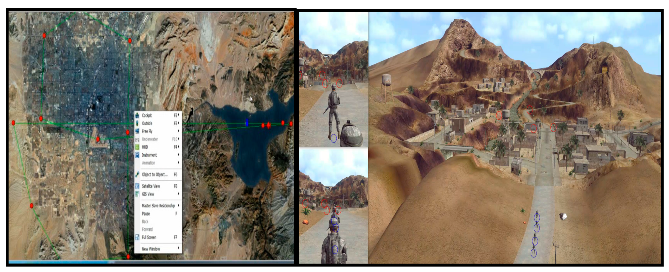
The simulations, in general, are designed to fit requirements and technical specifications (see Figure 1). Therefore, it is difficult to get many simulations to work together synchronized in time, space, and logic. We know that each simulation has a different logic in each aspect, such as commitment, representation, time, computational characteristics, human–machine interfaces, connectivity, and objectives. For this reason, only a few studies have been conducted, despite various motivations for and the feasibility of multiple-resolution modeling (MRM). Multi-resolution modeling is highly related to composability and define multi-resolution modeling as follows [4,5]:
- Building a single model with alternative users involving different levels of resolution for the same phenomena.
- Building an integrated family of two or more mutually consistent models of the same phenomena at different levels of resolution.
Kim et al. [6] state that an MRM approach can be conceptualized with this definition. The different levels of resolution could be implemented into a single model or family of models. These levels could be associated with the desired abstraction to describe a phenomenon. Rabelo [7] noted that “the level of abstraction or resolution in an MRM simulation approach can be related to the number of input/output parameters associated with a particular simulation model.”
Davis and Tolk [4] explain that a low resolution (more abstract) model, for example, might use 3–10 parameters to describe a particular model resolution space (different dimensions). However, depending on the complexity of the simulation scenarios to be implemented, the number of parameters for a particular resolution dimension (entity level, spatial, process, etc.) in a model might increase. Meaning that, due to a particular simulation event, a higher resolution model might be triggered, providing a higher number of parameters to describe a model resolution dimension.
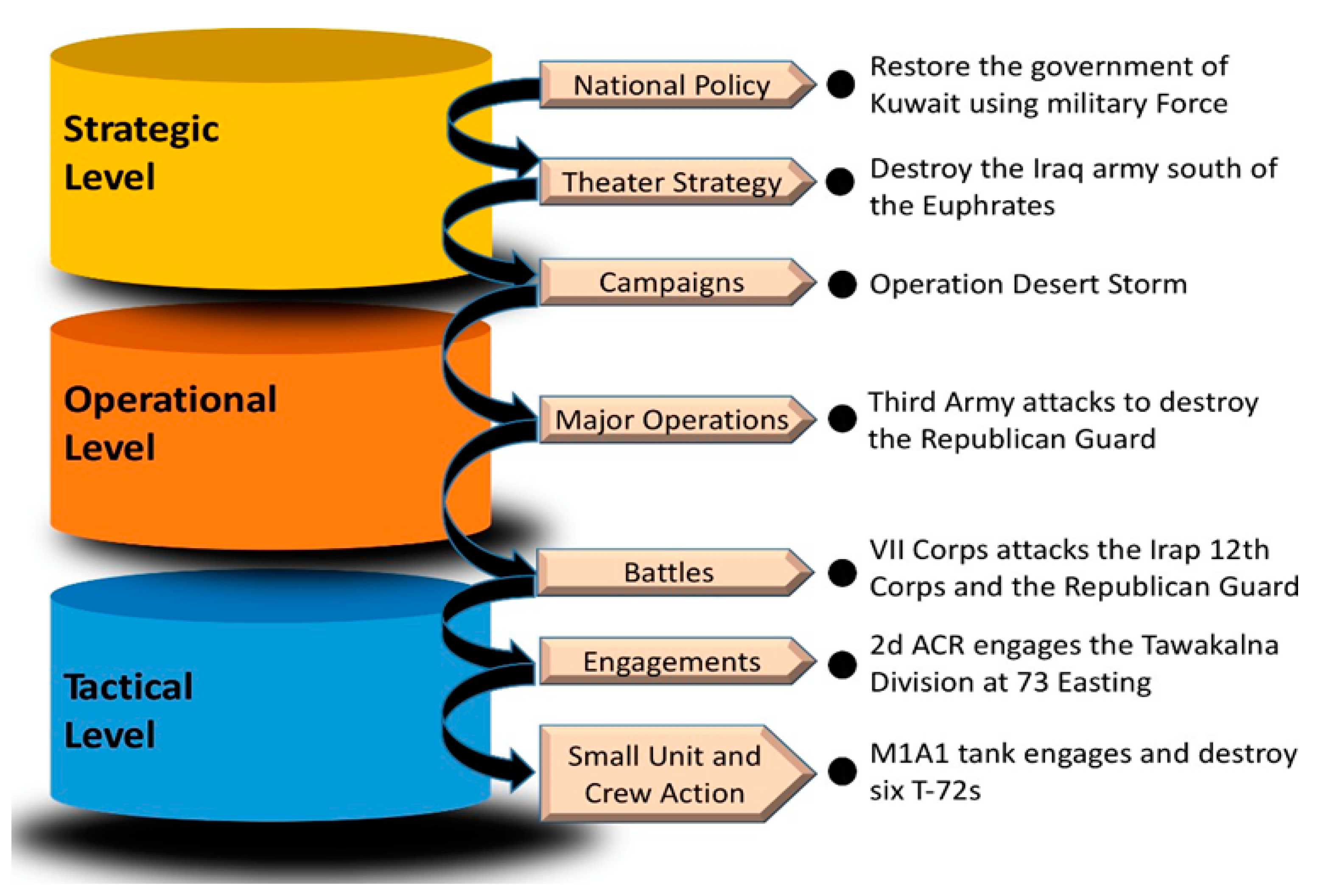
The concept of composability arises when you are devising an MRM approach implementation for a simulation system. Davis and Tolk [4] continue to explain that the traditional approach to MRM requires a “natural decomposition” of the system simulation models. Rabelo [7] stated that “the reason is that the MRM approach should be implemented in a hierarchical structure to support the definition of aggregate and disaggregate levels of models in a simulation” (Figure 2).
Davis Paul and Bigelow [5] articulated the obstacles of MRM in their paper titled “Experiments in Multiresolution Modeling” as follows:
- The model developer had no guidelines for MRM design. When switching to low resolution, the poor conversion strategy discards important information degrades the MRM system.
- Aggregated models sometimes yield the wrong result because of unreasonable reasons. This problem can be described as a data mapping problem or inconsistency problem.
- People expect many things from the MRM system, set high standard goals, and then reject the MRM system when it fails to meet their requirements.
2. Resolution
Resolution is a fundamental concept for MRM. Resolution is defined as “the degree of detail and precision used in the resolution of real-world aspects in a model or simulation” [8]. The question remains what kind of details there should be, and what parameters to use to measure whether it is low or high resolution.
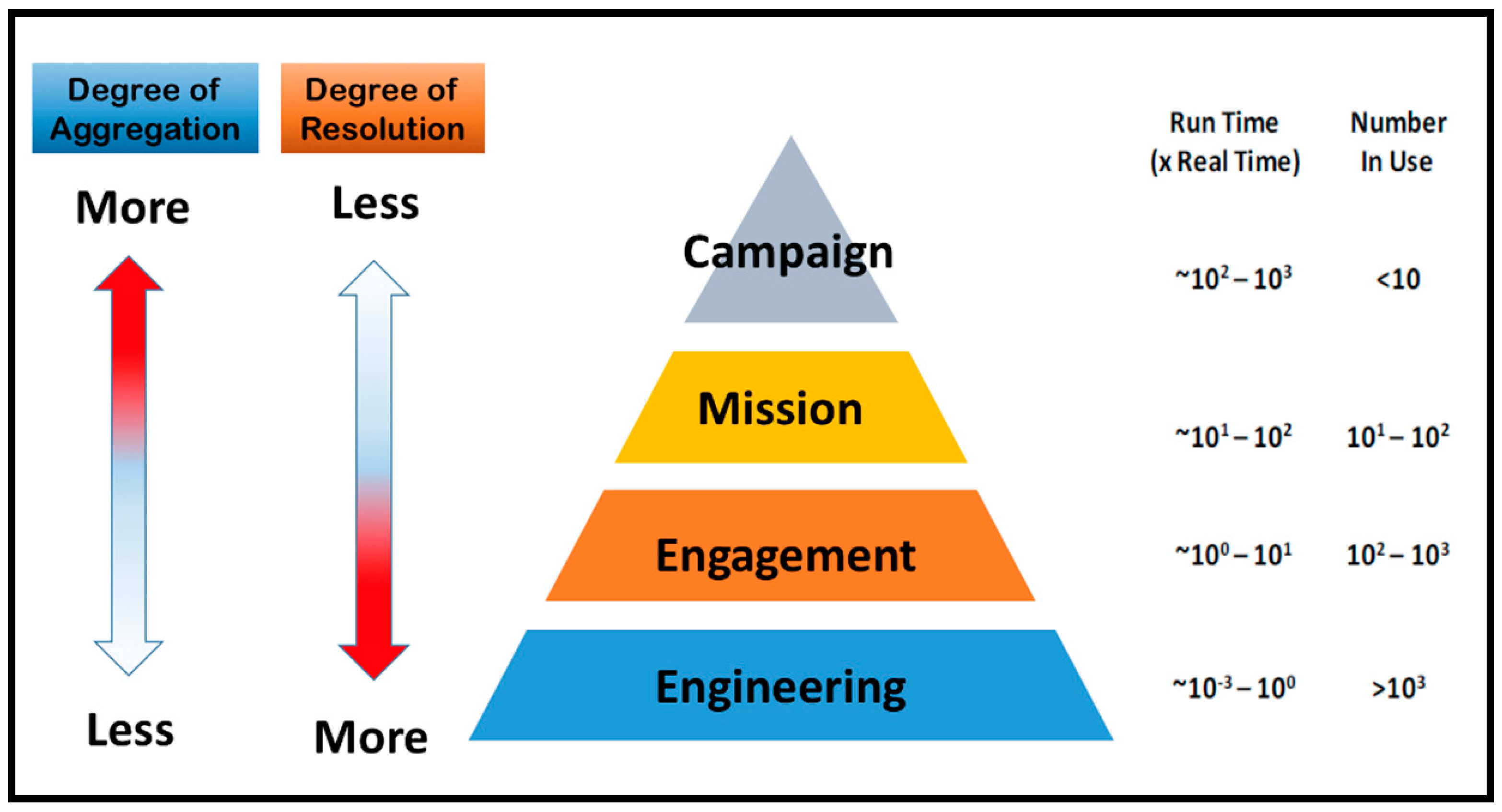
Mullen et al. [9] describes an example of the temporal scale using the modeling and simulation pyramid shown in Figure 3 for military simulations. The degree of resolution decreases as one moves from the engineering to the campaign level. Execution times, as a multiple of real-time, vary significantly across the levels.
Let us illustrate the resolution concept with the complexity of the military. Campaign level simulations must be able to represent 90 days of combat. Because they are typically executed many times for uncertainty analysis, there needs to be an ability to execute very quickly for the simulation to be useful. If a simulation is needed for a decision-maker to decide which method is the best, a quick-run would be the most useful. Mission level simulations typically execute 10–50 times faster than real-time. Engagement level simulations typically operate in the real-time range or slightly faster but simulate a shorter period. For instance, a simulator which is designed for training pilots should run in real-time to provide a similar environment and experience compared to the real world. At the engineering level, run-times are diverse as there is a mix of the other three levels combined with some very computationally intensive simulations.
The relationships of resolution among components of a distributed simulation system can be confusing and complicated. The resolution of a particular model can be lower in some aspects, higher in others, and the same in the rest. Aggregation and disaggregation are closely related to the resolution. On the other hand, the quality of resolution cannot be judged solely based on whether it has an aggregated unit in its model; this does not equate to a low-resolution model since the resolution is a relative concept [10]. When it comes to comparing two models A and B, model A could have a higher resolution in some aspects, but the lower resolution in other aspects. Therefore, it is not an easy task to decide which models are higher than others, and MRM is a part of the art of deciding what level of detail is needed in various aspects [5].
The core of resolution in MRM is not a matter of which simulator is higher or lower resolution than others. The goal of MRM is to achieve users’ requirements by connecting different resolution simulations.
3. Composability and Interoperability
When researching an MRM approach implementation for a simulation system, the concepts of composability and interoperability arise. “Composability is the capability to select simulation components and assemble them” in a variety of arrangements to make a sound simulation modeling system to meet user requirements [11].
The definition of interoperability is the ability of a computer system to run programs from different vendors, and interact with other simulations or computers across local or distance- area networks regardless of their operating systems and physical architecture [11].
Davis and Tolk [4] differentiated interoperability from composability. Interoperability is the “ability to handle software and implementation details containing data exchange elements based on data interpretation, which can be distributed to the levels of semantic and syntactic” interoperability. Interoperability focuses on how the models are executed. Composability describes the components on the modeling level. The model is an essential abstraction of the reality used in the abstraction implemented by the subsequent system. Composability considers contextualized, conventional conceptual models [12].
4. Current Issues of MRM Distributed Simulation Systems
MRM focus on resolving representational and conceptual gaps arising from multiple resolution levels in federated distributed simulations. The main issue is simulating an object and its attributes concurrently. If an abstraction of the object and its attributes are simulated concurrently, then all interactions in overlying specific periods with the same abstraction and its federates will be at both levels [13]. However, many issues arise with simulation couplings, such as data consistency and temporal inconsistency.
Data consistency has many facets that need to be addressed, such as data distribution problems, syntax, semantics, pragmatics, assumptions, and validity consistency. All of these facets are required to build a sound MRM system. First, keeping the consistency of syntax means that two simulations or models can work together at an engineering level [4]. If there are differences with syntax, then one sub-model cannot compute or understand information from the other sub-model. Therefore, the same protocols are essential to deal with this problem. Second, the “consistency of semantics ensures that data have the same meaning in the sending and receiving model” [4]. Consistency of semantics means that the data which is produced by a model has the same meaning when it is used in a different model. Tolk [14] recommended using a standard reference model to overcome these issues by distributing information exchange objects to standardized data elements. Solutions are languages based on the Protocol Data Units of the Distributed Interactive Simulation Protocol, or a standardized reference model. Third, consistency of meaning is not always the same, because the same word could mean different things depending on the context. Even though semantics make sure that the individual data are straightforwardly identified, pragmatics puts those data into the context of how they are used in the simulation or model. Although models agree on the meaning of all data elements to exchange, these data elements can be used in different situations, making it difficult to exchange these data in the execution environment. Fourth, the difficulty continues even after consistency is maintained across models, due to the way words are used. Sometimes, it is a matter of accuracy or precision, but in other cases, it is much more subtle. Fifth, there remains a question about whether the model is correct. Also, a model that is appropriately valid in one context may not be valid in another context [4].
Temporal inconsistency can occur when two entities have been “conflicting or inconsistent representations of the state of a third entity at overlapping simulation times” [15]. Typically, a high-resolution model runs its simulation based on real-time, but a low-resolution model used to implement time-stepped. Time synchronization issues are typically observed in linkages that run at very different time levels with different resolution levels. For example, two entities A1 and A2 interact with each other once every minute in a low-level resolution model. A1 and A3 interact together in every second in a high-level resolution model. Temporal inconsistency occurs in this case because A1 interacts with A2 once a minute, but A3 interacts with A1 60 times a minute. A3 forces A1’s state to change sixty times, but those interactions do not adequately are reflected in the low-resolution model. This process causes a temporal inconsistency because A2 and A3 have inconsistent representations of A1 at the end of the larger time-step. Temporal inconsistency directly degrades the reality of the MRM federation.
5. Taxonomy
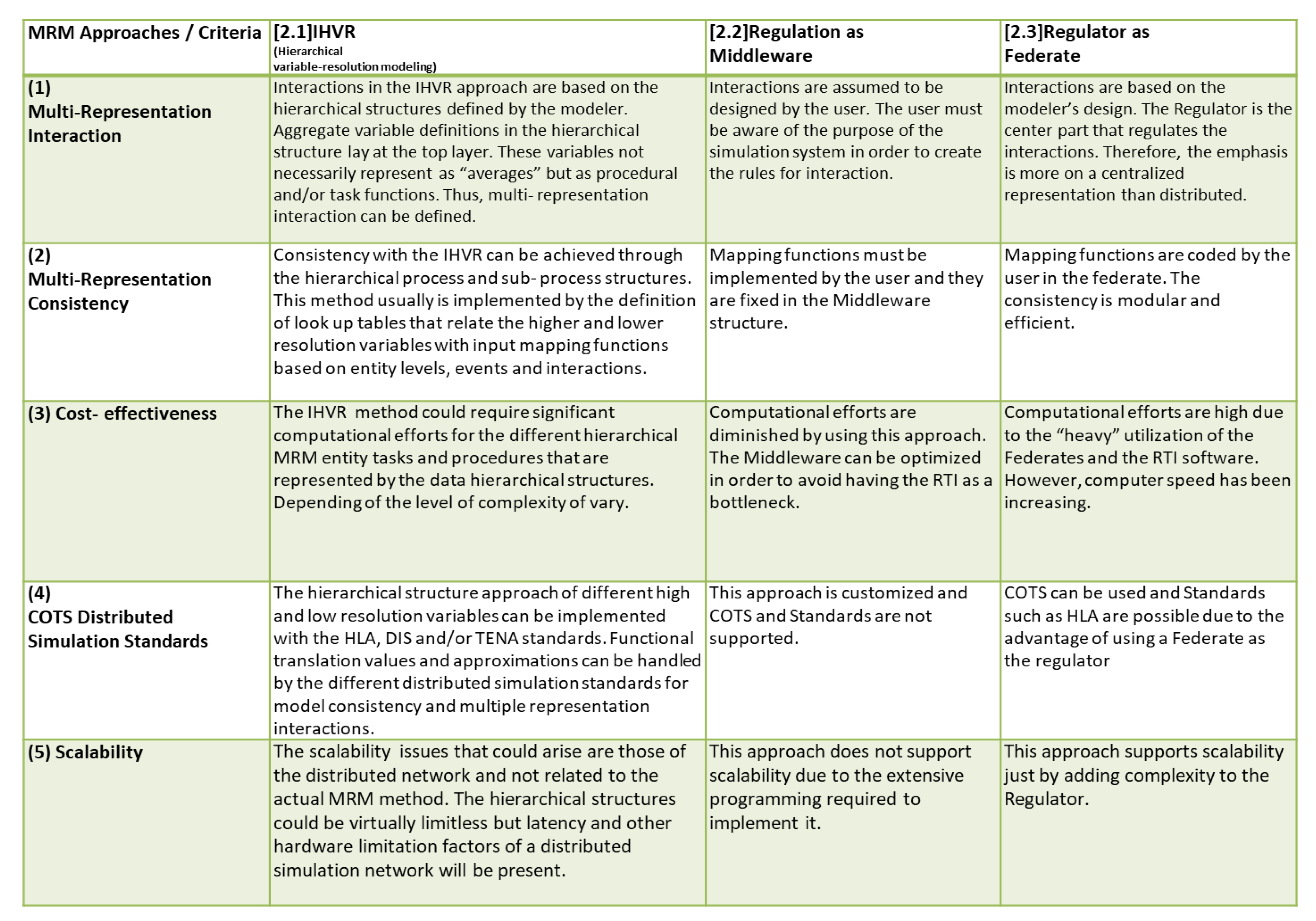
We have investigated the different approaches being used and built a unique taxonomy. They are different categories, and it will be presented in three different groups. The dimensions to compare the significant approaches to MRM are multi-representation interaction, multi-representation consistency, cost-effectiveness, the potential to use components off-the-shelf (COTS) based on distributed simulation standards, and scalability of the approach.
The first group is displayed in Figure 4, is composed of the hierarchical variable-resolution (IHVR) modeling approach, regulation as a middleware, and regulator as a federate of a complex distributed simulation.
Integrated hierarchical variable resolution (IHVR) modeling is an MRM approach developed that describes a procedure-oriented method that uses a hierarchical variable tree. The main variables are depicted in hierarchical trees with the lowest-resolution variables at the top. This hierarchical variable tree goes from low resolution to high resolution. Therefore, aggregation is at the top, and the most disaggregated areas are at the bottom.
The regulator as middleware was introduced by Tan et al. [16] as an alternative method instead of the module-based approach. The regulation as middleware is a system which puts the modifier, such as the aggregation/disaggregation approach, on the middleware. Thus, middleware controls the aggregation/disaggregation procedures among federates. The middleware approach attaches another layer of interface between federates and the Run Time Infrastructure (RTI). This middleware regulator layer handles all disaggregation and 35 aggregation requests from federates. Therefore, the RTI is not involved in those interactions. This method reduces the workload of the RTI.
The regulator as the federate approach is also one of the alternative methods instead of the module-based approach in Tan et al.’s [16] paper. This approach suggests that building a regulator as a separate federate will control all required interactions of disaggregation. The regulator federate stores the database of information within itself. The regulator as federate is not only in charge of the interaction of aggregation/disaggregation, but it also decides which lower level federate associations will handle the interaction when disaggregation is needed. If it is not necessary, the federation will ignore the interaction (dynamic change), and the federation will perform normally. If necessary, federation 37 accesses the database and extracts the information that should be sent as input parameters to the low level federate that will process the disaggregation.
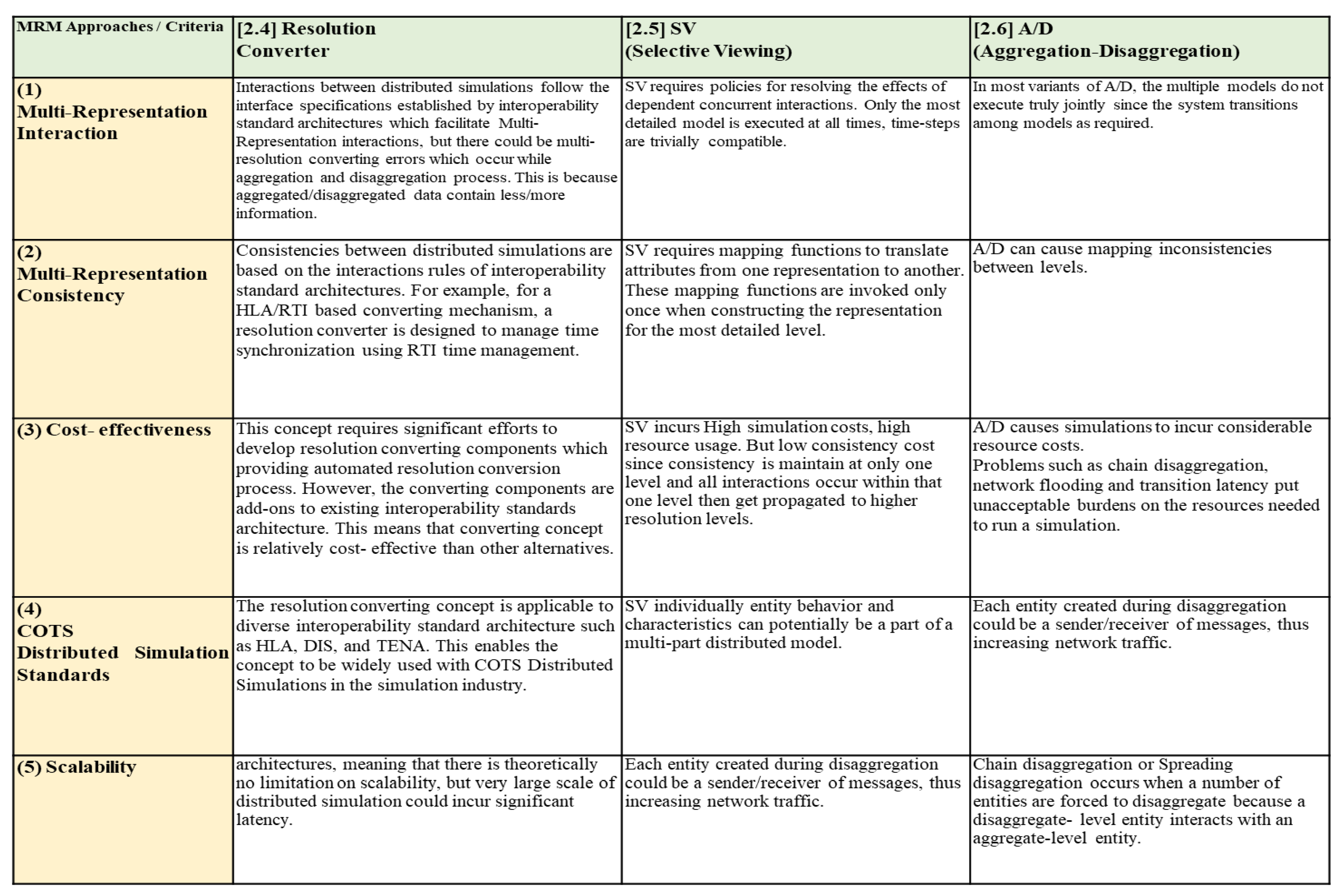
The second group as shown in Figure 5, is composed of the resolution converter, the selective viewing (SV) approach, and the general aggregation–disaggregation approach (A/D) [17].
The resolution converter is one of the methods to solve the problem of resolution mismatching in communication between simulators for distributed simulation of multi-resolution models. The approaches act as a solution by transforming data formats and managing time synchronization in the multi-resolution modeling.
Hong [8] suggested developing the architecture of the multi-resolution converter to HLA/RTI to exchange data among distributed simulation models. However, the details of this concept will not be handled in this paper. It is a similar concept to the regulator which was discussed before, and can vary according to what kind of methods the system builder wants to add. Furthermore, it cannot be a cookie cutter method for every simulator or MRM system.
Selective viewing (SV) is another one of the traditional MRM approaches, in which the most detailed, highest resolution model, is running at all times, zooming and un-zooming capability presenting a display of various resolutions are included. It is based on the principle that having more detail is more important than the entities’ performance. Selective viewing depends on the highest resolution model that interacts with the low resolution model after a short while in the simulation. It is similar to the construction of model-view-controller (MVC) in software design. MVC is a software architectural pattern for 40 implementing user interfaces [18]. It has three parts of a software application: model, view, and controller.
Multi-resolution combat models need the capacity to change a low-resolution level to a high-resolution level, or vice versa, respectively while simulating models. One of the various resolution change methods is aggregation–disaggregation. Aggregation objects mean a unit level consisting of various entity levels, while disaggregation objects represent an entity level which cannot be further decomposed [19]. Disaggregation can be triggered by an event where aggregate units are separated into a lot of entities at a lower abstraction level, each representing a higher resolution component [16]. Aggregation is also triggered in some situations where the federates need to control the aggregated unit, and then the entity is simulated independently.
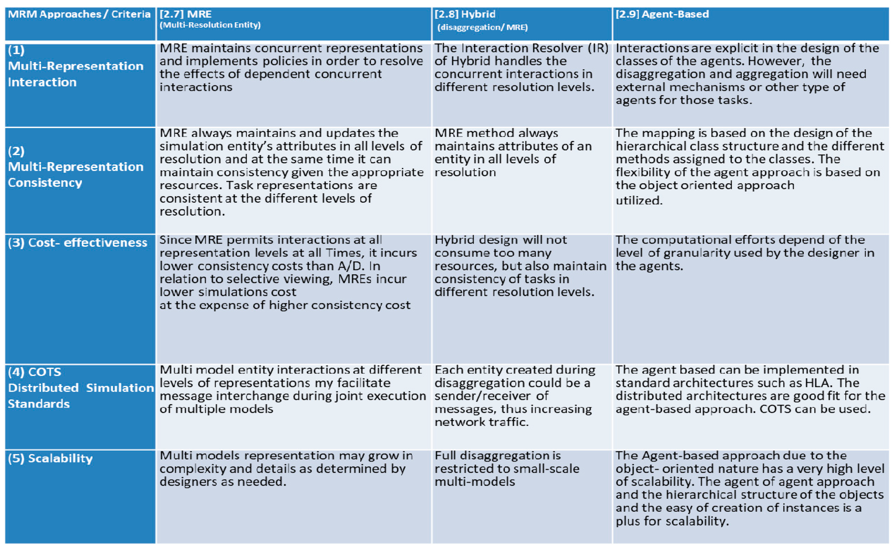
The third group, as shown in Figure 6, is composed of three advanced and popular methods, the multi-resolution entity (MRE), the hybrid based on disaggregation and MRE, and the agent-based one [20]).
The multi-resolution entity (MRE) concept for interacting at multiple levels of resolution simultaneously, referred to as MRM from here on. This concept is one of the methods to maintain consistency of constituents during a series of aggregations and disaggregation. It is how to keep records for entities or units while avoiding inconsistency in MRM. According to Reynolds Paul. F. [15]: “an MRM interacts with consistent properties across matched properties at different levels of resolution. Each MRE maintains state information at all desired levels of resolution or provides the requested level of information immediately.”
The aggregation–disaggregation was the commonly used approach and was considered to represent the nature of MRM best. However, this approach may lead to inconsistencies between the various levels of resolution. On the other hand, the MRE approach always maintains the attributes of an entity consistently at all levels of resolution. However, MRE can be consistent while sacrificing more resources and software costs. The hybrid method is designed to reduce or eliminate transition overheads, in other words, chain disaggregation. In the perspective of interacting at multiple levels of resolution simultaneously, it is a similar concept with MRE, but they have diverse ways to maintain consistency. According to Reynolds Paul. F. [15], a hybrid approach maintains a consistent attributes core across the resolution level. The core is a subset of the entire set of attributes, consisting solely of attributes that are considered essential. As needed, the values of additional attributes are generated from values at the core level.
Agent-based simulation has gained more popularity recently, especially in areas where behavior is important, because of its powerful capability of capturing behavior in detail and imitating the system interactions and dynamics [21]. The increasing numbers of conference proceedings and journal articles that call for agent-based models are evidence of its popularity and growth [20]. The agent-based simulation would provide better results under certain scenarios, because the legacy modeling tools may not be enough to capture the complexity of the real world. Although there is no universal agreement on the exact definition of the agent, the fundamental characteristic of an agent is the ability to make independent decisions that are working itself. The agents have a behavior and can make decisions. They also interact with the objects and other agents. Furthermore, agents can form groups and act individually. In this perspective, we can use an agent-oriented approach to more closely match the characteristics required by the military and operational view of problems.
6. Practical Steps to Build an MRM System
The current MRM approaches, which were presented in the previous section, are solutions that have a different focus on the MRM issues/problems. Some approaches are solutions for simulation design, which can be MRM, such as IHVR, and agent-based. However, there are some specific problem resolutions like MRE or hybrid. These approaches are methods that need to be reviewed at different steps during the development of an MRM. A meaningful MRM federation is to connect simulations (or federates) with different levels of resolution (high or low) to meet the needs of the user. Therefore, the following three steps are essential to build an MRM system and categorize the current MRM approaches into each step:
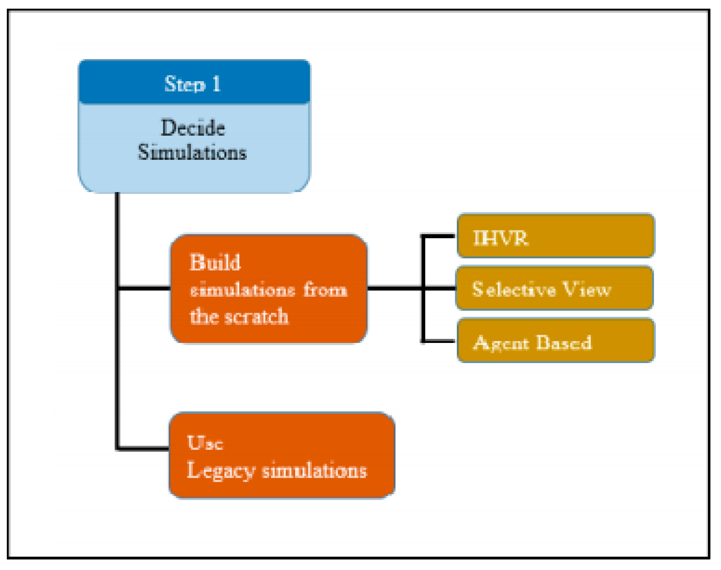
Step 1: Decide to Develop a New Simulation or Reuse
Most existing simulations have inherently limited interoperability because they were not designed to work together. If one wants to build a whole simulation to make it work in a federation, then it can be built seamlessly and is an ideal MRM federation in some aspects. As shown in Figure 7, integrated hierarchical variable resolution (IHVR), selective viewing (SV), and agent-based approaches can be adapted if one wishes to build a new simulator or simulator for MRM.
Building an MRM system can create a seamless MRM federation. It can be designed to avoid data inconsistency or time synchronization issues between low and high-resolution models. On the other hand, it can be costly. If a user wants to build the MRM federation system by using legacy simulators, then the builder must consider which simulators will participate in the federation to meet the user’s requirements.
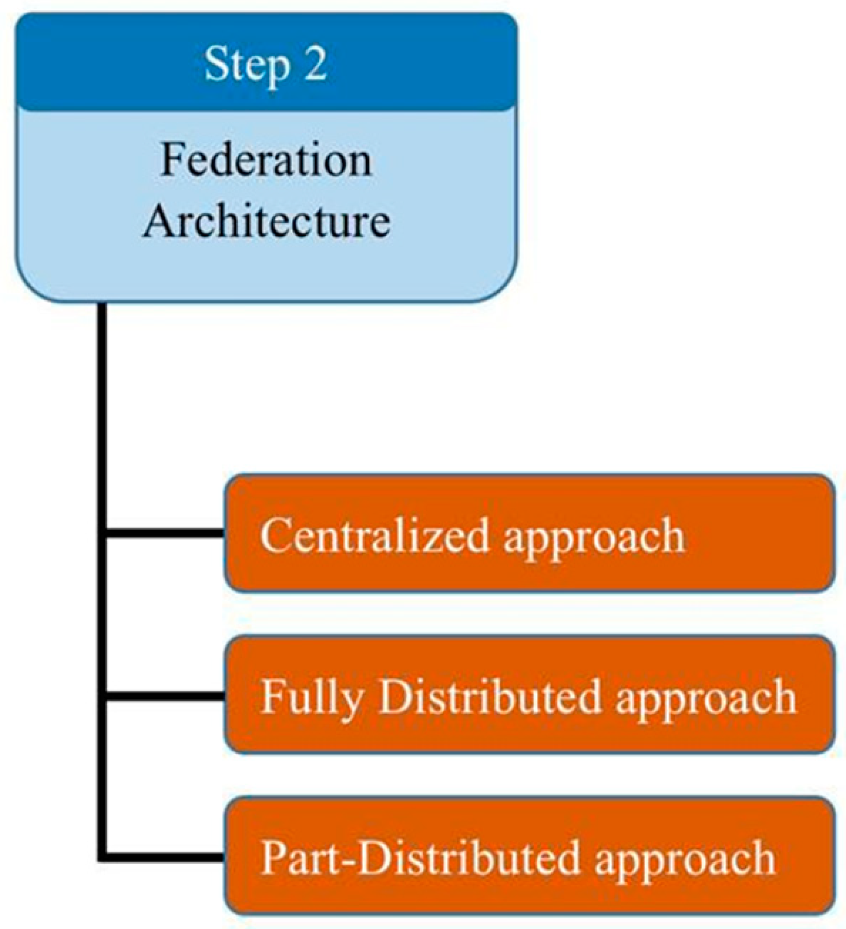
Step 2: Federation Architecture
If the builder decides to use legacy simulators for an MRM system, then they might face the problems that were discussed in Section 4, the current issues of MRM Distributed Simulation Systems.
When the developer wants to build a federation among the different levels of simulations, they have to consider the federation architecture at first. According to Martin & Pierre [22], there are three federation architecture approaches; centralized, fully-distributed, and part-distributed approaches (Figure 8).
Martin A. & Pierre S. [22] said that a single federate ensures the simulation of both low and high-resolution entities in the centralized approach. The method is to absorb several high-resolution simulations in a low-resolution simulation and make them work as part of a low- resolution simulator engine. This approach needs re-engineering of all simulations which participate in the federation.
Conversely, a fully distributed architecture, is designed for each aggregate or disaggregate entity to interact with its own federates. In this architecture, each federate may run on different hosts of the network.
The part-distributed architecture can provide a compromise between the number of messages exchanged and the distribution. The architecture is simple, each federate takes charge of a specific resolution.
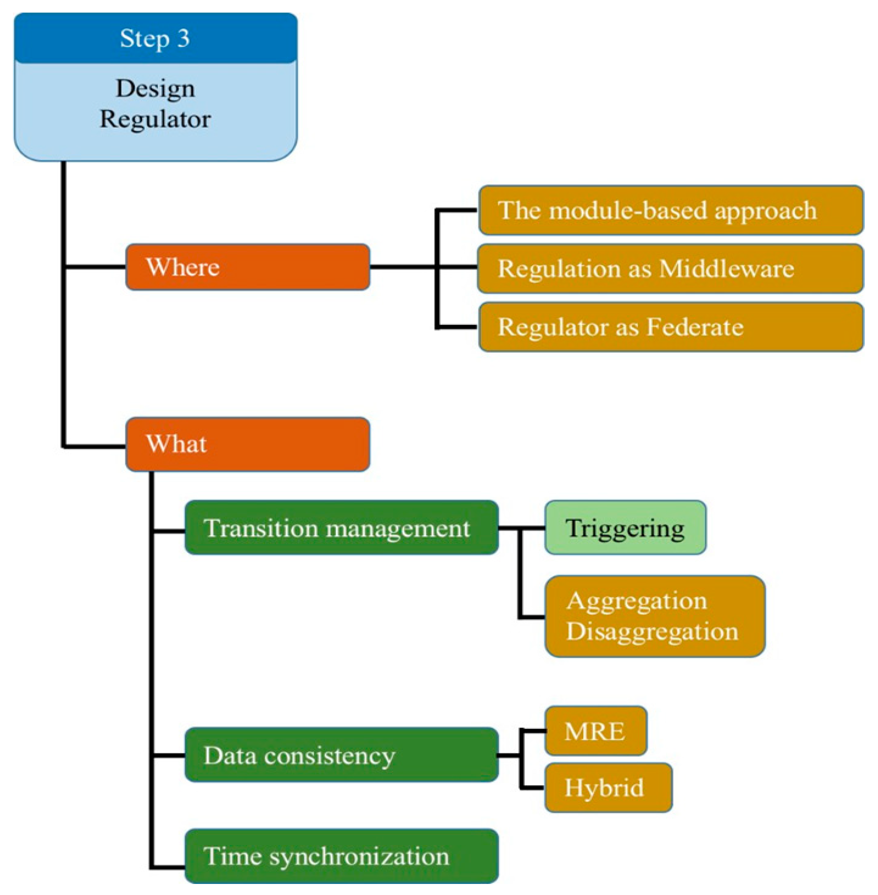
Step 3: Design Regulator
The regulator controls the ownership and changes the information for the sub-federates to fit each other. As shown in Figure 9, the Regulator can vary based on the function of the regulator and where the builder placed it. In some papers, it is called a resolution converter. It works as an interpreter and coordinator in the federation.
Engineers can build without a regulator, but it will result in a less powerful MRM. An MRM without a regulator has major data inconsistency problems, or they cannot share any data among federates because each federate could have different attributes for running their simulation engines. Only a certain amount of information can be shared if the federates build the same standard simulation architecture (SSA) like an HLA.
The design of regulators is the core of building a seamless MRM federation system. The standard simulation architecture (SSA) provides a rough linkage among federates, but the higher resolution gap among federates causes more problems in the federation. Therefore, adequate modifications are needed. Re-engineering of simulations would be expensive, so the regulator can be an alternative method to relieve MRM problems. There are two major considerations:
- What to put in the regulator: transition management is a way to manage the level gap of information among federates. When MRM changes a low-resolution level to a high-resolution level, MRM will change one side’s information to make it suitable for the other side. For example, there is a tank squadron unit which consists of four individual tanks in a low-resolution model (MASA Sword). A high-resolution model (SIMBox Simigon) is a simulation which can only represent individual tanks; therefore, the low-resolution model information needs to be changed to be compatible information for the high-resolution model or vice versa.
- Where to put the regulator: If the developer decided on what kind of MRM approaches they want to include in the regulator, the next thing to consider is where to put the regulator. There are three different options to attach the regulator in an MRM federation system:
- The module-based approach
- Regulation as middleware approach
- Regulator as federate approach
Each approach has a different position for the attaching regulator, they each have has pros and cons; there is no way to determine which approach is better than the other because the best method depends on the user requirements and federated (simulator) characteristics.
7. Example of an MRM System
This scenario was developed to show a concept of MRM. For this purpose, COTS simulators were utilized. The simulations were connected through the HLA/RunTime Infrastructure (RTI) [6,23,24].
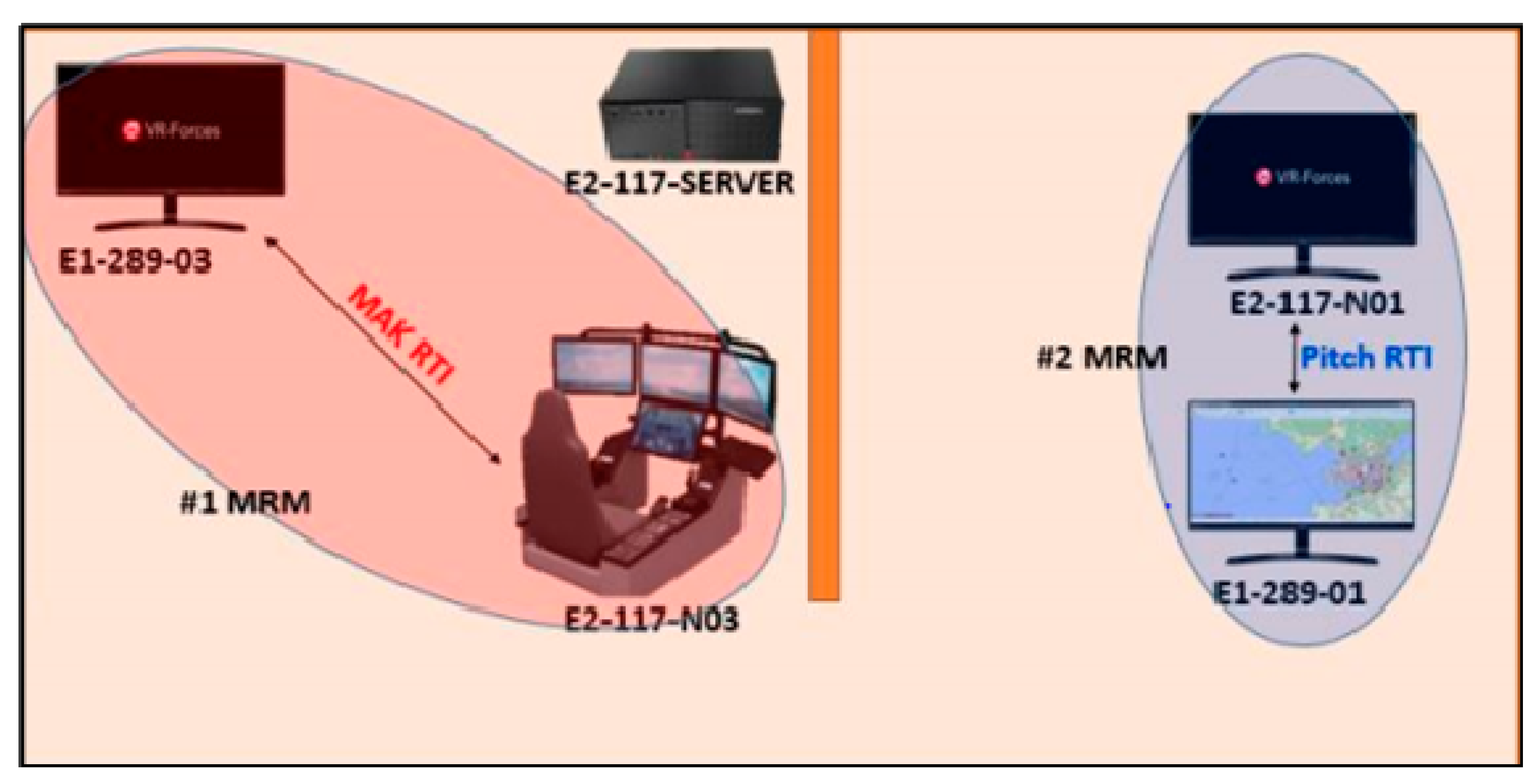
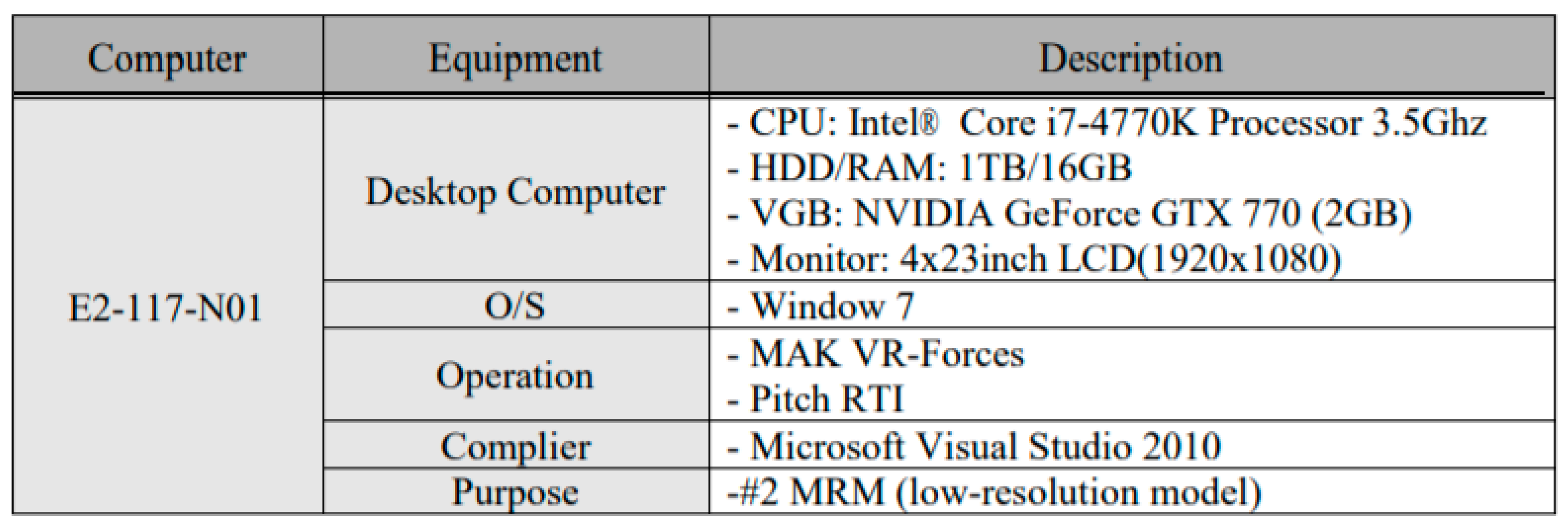
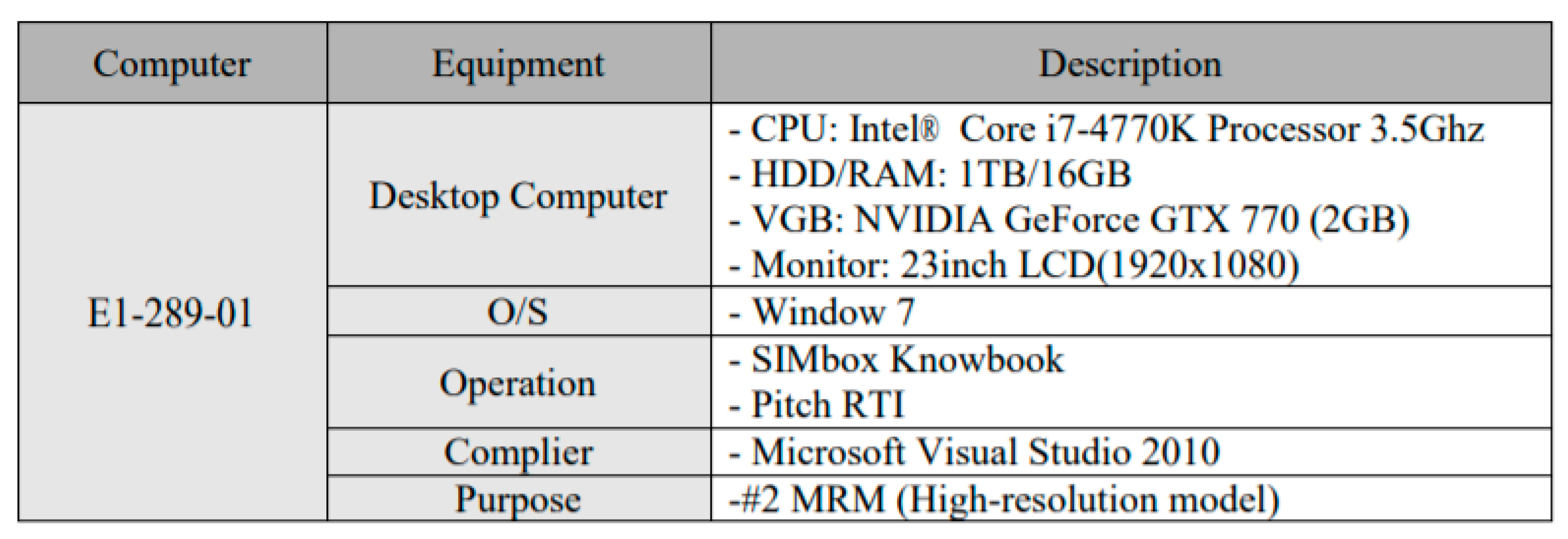
7.1. Hardware
7.2. Software
Two COTS simulators are used for the study in the UCF Simulation and Interoperability Lab. Two MRM federations are going to be constructed using these simulations differently.
MÄ K VR-Forces (https://www.mak.com/products/simulate/vr-forces) MÄ K VR-Forces graphical user interface (GUI) provides the user with a 2D and 3D view of a simulated environment where the interaction between all entities can be observed. It is a powerful and flexible simulation tool of the environment for the generation of distributed simulations scenarios. VR-Forces satisfy the requirements of HLA standards.
MASA Sword (https://masasim.com/tag/sword/) MASA Sword is designed for the operational level of warfare. It is an excellent simulation for commanding post exercises, using an aggregated unit like divisions, brigades, battalions, and companies. Opportunistic behaviors drive units in this simulation, and the user can modify the behavior based on their military doctrine. Therefore, it can reduce human intervention for every unit movement.
7.3. MRM Scenario
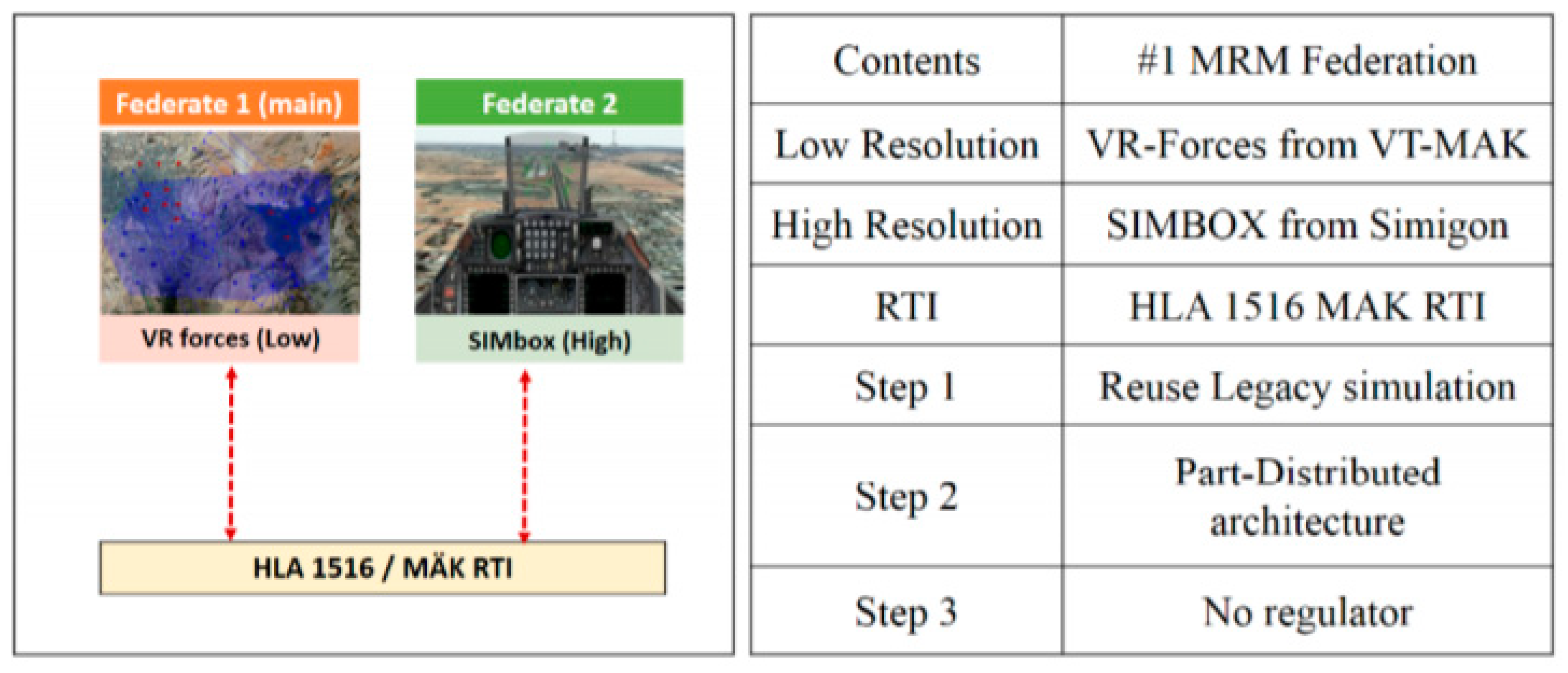
MASA Sword simulation is used as a low-resolution federate, and VR-forces participate as a high-resolution federate. As shown in Figure 13, this MRM federation uses two different COTS legacy simulations, MASA Sword & VR-Forces (Step 1), and the part-distributed approach is used as the architecture of federation (Step 2).
An aggregation–disaggregation approach is applied for dynamic changes from the unit to the entities. Geographical and time-based triggers are applied to these dynamic changes. Therefore, the MRM uses a regulator for the operations of aggregation–disaggregation, a geographical trigger, and a time trigger (Step 3, what to put in the regulator).
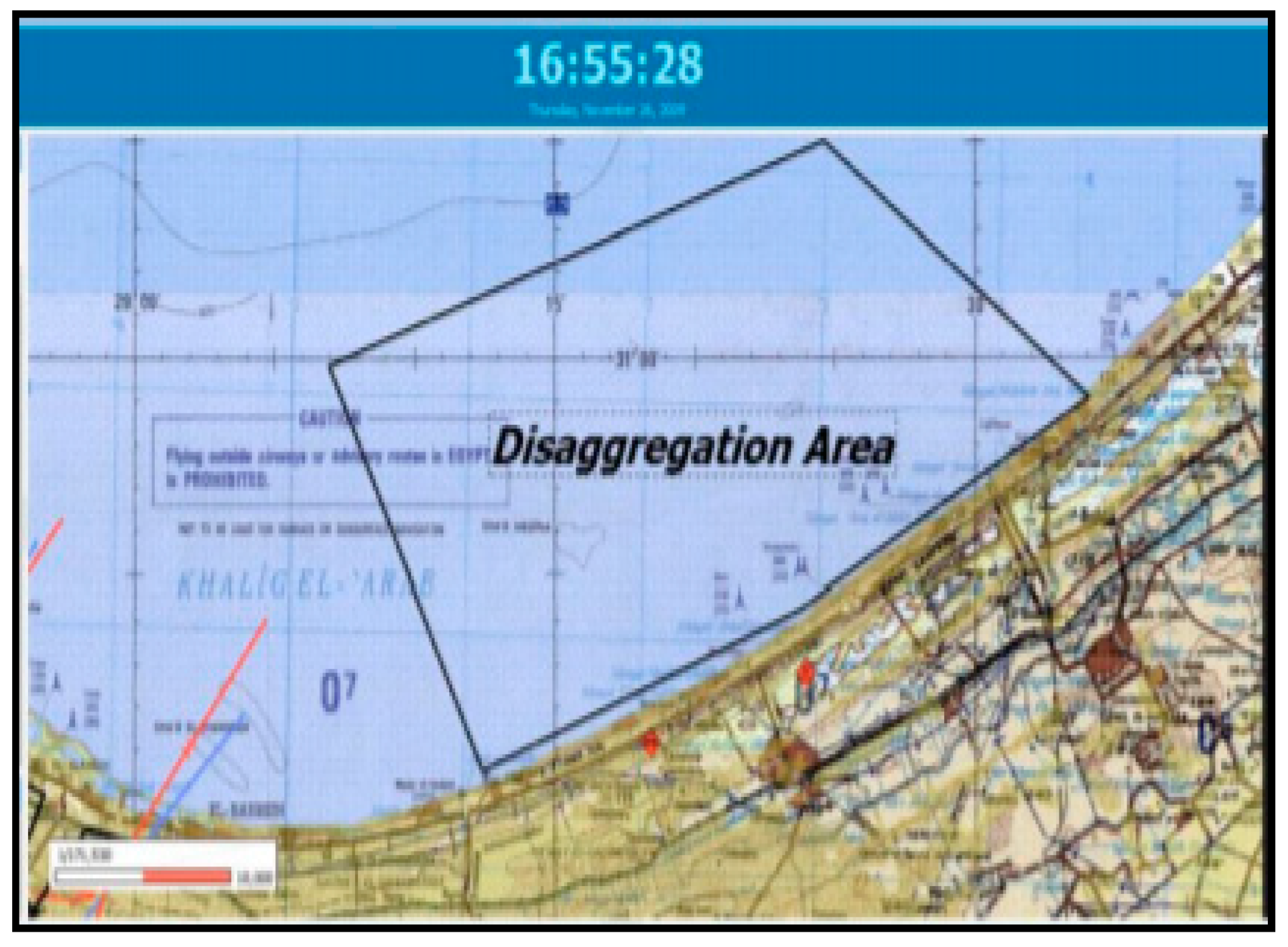
The control function works through figures/polygons that the user has to define. For example, the user can define an exclusive geographic area with a polygon. So using these specific polygons in a section, we can pass control to another simulator (i.e., another federated), and that is the geographic trigger. The polygon was linked to the control function (Figure 14) in our example. The polygon in Figure 14 represents a disaggregation area, which means that each time a simulated unit/agent enters that area, its ownership is automatically granted to another federated. For example, when the MASA Sword Aggregate Unit passes through the polygon section, then the control function is activated in MASA Sword. This means that MASA Sword assumes its right to control VR forces in the distributed simulation. VR Forces can create multiple entities based on information from MASA Sword and control those disaggregated entities in the VR Force simulation environment. When the unit leaves the polygon board again, MASA Sword can regain control of its units and have the aggregate function used to have the unit automatically.
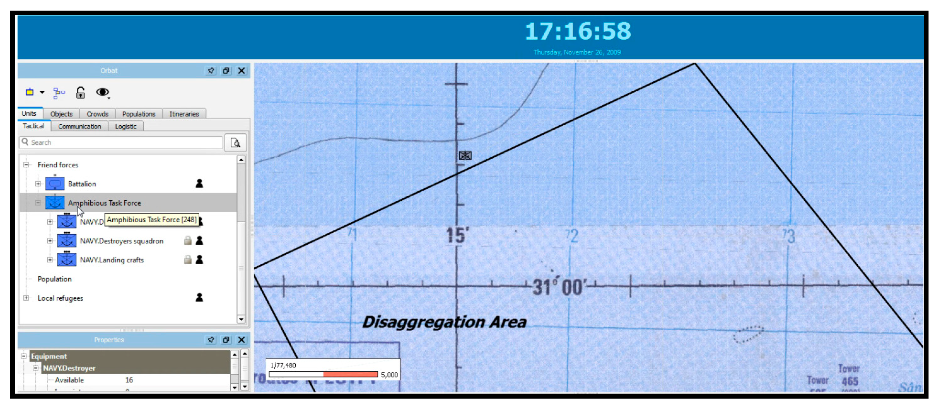
This MRM system also uses a “geographic trigger” and a “timeline function” to build a time trigger for the simulation that is on the MASA Sword platform [6,19]. The “timeline” is a feature that allows individual units to place a specific order at a specific time. If the user gives an order to move the unit beyond the unbundling area at the designated time, control of all units passes to VR-Forces (and the simulation model in MASA Sword leaves control) (Figure 15).
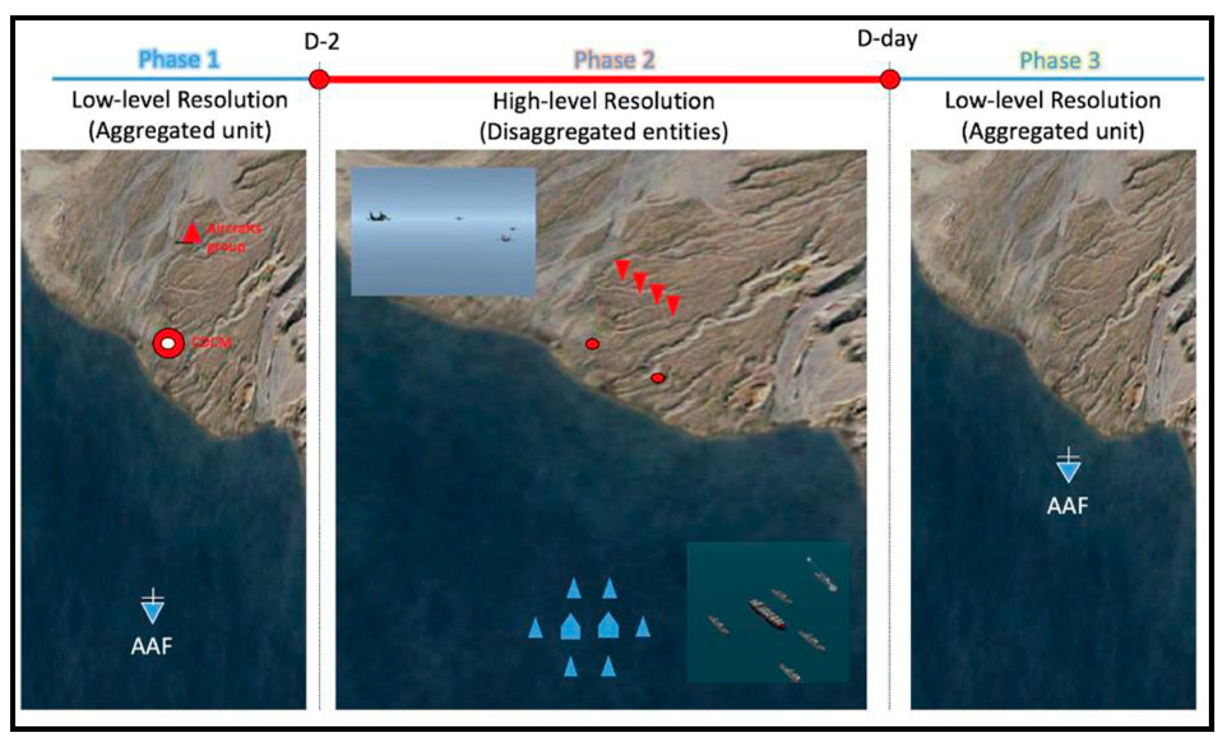
The scenario for the MRM federation system is also based on naval combat. In this scenario, two aggregated units will be disaggregated by the time trigger. The time trigger will be needed in military simulation because most military operations use the ‘D-day’ notion for building a plan of attack. D-day is a military term that has various meanings, it could be the landing operation day or starting a raid day like the famous Normandy Beach Landing operation. The military used to set up specific actions for their operation based on D-day. For example, D-2; Deploy amphibious forces in the operation area, D-1; Search and sweep enemy submarines in the operation area, neutralization of all enemy’s Coastal Defense Count Missiles (CDCMs), D-day; landing marine corps in the targeted shore. This scenario will be designed according to time-based factors. An aggregated unit will undergo a disaggregation process at a particular time, and when they finish their mission at a specific time, they will aggregate.
As shown in Figure 16, blue force Amphibious Assault Force (AAF) is trying to approach the landing shore in the low-level resolution model. Red forces consist of two different units, a CDCM group and an aircraft group to protect the target area and operate the anti-access strategy. All units are running in the low-level resolution during phase 1. Three different large groups of units maneuver to achieve their tasks; (1) AAF: approach to the targeted shore, destroy or neutralize enemy CDCM and aircraft group, convoy landing ships. (2) CDCM: destroy or neutralize AAF using the surface to surface missiles. (3) Aircraft group: destroy AAF.
At a particular time (D-2), All Units (AAF, CDCM, and aircraft group) are disaggregated. The disaggregation process instantiates the individual entities that make up the disaggregating unit in the entity level model (i.e., the high-level resolution). This disaggregation assigns a location on the battlefield at the entity level based on the central location of the unit. That means all interactions among entities will change attributes in high-level resolution models; those changes should reflect the attributes in the low-level resolution models simultaneously.
8. Conclusions
MRM is a unique form of distributed simulation that emphasizes the united execution of multiple models. MRM is a substantial challenge for distributed simulation and one that ultimately promises to be able to power complex and heterogeneous model simulations. The literature and our experience have taught us to categorize the different schemes for doing MRM. From experience, we have been able to make a guide for the application of MRM and follow the steps. These lessons learned have led to the use of COTS and thus decrease development time. The experiment tells us that COTS helps to make good MRM designs even with legacy models. Our experiment confirms the assumption that modern simulation COTS products created using current and future interoperability standards can communicate efficiently. COTS can help modeling and simulation endeavors to address the different requests of an audience using MRM. Disaggregation and aggregation are becoming more achievable with new technologies implemented in the latest simulation tools and share standards like HLA [25].
Funding
This research was funded by the Defense Acquisition Program Administration and Defense Industry Technology Center under the contract UC160003D, Korea.
Conflicts of Interest
The authors declare no conflict of interest.
References
- Jung, W. An Analytic Framework of Weapon Combat Effectiveness Using the Big Data Generated by Live, Virtual, or/and Constructive (LVC) Simulations: Three Case Studies Constructive, Live, and Limited LVC Simulations. Ph.D. Thesis, University of Central Florida, Orlando, FL, USA, 2017. [Google Scholar]
- Reid, M.R.; Powers, E.I. An Evaluation of the High Level Architecture (HLA) as a Framework for NASA Modeling and Simulation. Available online: https://www.semanticscholar.org/paper/An-Evaluation-of-the-High-Level-Architecture-(HLA)-Reid-Powers/7b0489595a033cbbbaa312e688704a6d158307a8 (accessed on 29 September 2020).
- Dahmann, J.S.; Fujimoto, R.M.; Weatherly, R.M. The Department of Defense High Level Architecture. Available online: https://www.informs-sim.org/wsc97papers/0142.PDF (accessed on 29 September 2020).
- Davis, P.K.; Tolk, A. Observations on new developments in composability and multi-resolution modeling. In Proceedings of the 2007 Winter Simulation Conference, Washington, DC, USA, 9–12 December 2007. [Google Scholar]
- Kim, J.; Lee, K.; Marin, M.; Lee, G.; Rabelo, L. Development of the Multi-Resolution Modeling Environment through Aircraft Scenarios (No. 2018-01-1923). SAE Tech. Paper 2018. [Google Scholar] [CrossRef]
- Rabelo, L.; Kim, K.; Park, T.W.; Pastrana, J.; Marin, M.; Lee, G.; Gutierrez, E. Multi resolution modeling. In Proceedings of the 2015 Winter Simulation Conference (WSC), Huntington Beach, CA, USA, 6–9 December 2015; pp. 2523–2534. [Google Scholar]
- Davis, P.K.; Bigelow, J.H. Experiments in Multiresolution Modeling (MRM): DTIC Document; RAND Corporation: Santa Monica, CA, USA, 1998. [Google Scholar]
- Hong, S.-Y.; Kim, T.G. A Resolution Converter for Multi-resolution Modeling/Simulation on HLA/RTI. In Systems Modeling and Simulation: Theory and Applications, Asia Simulation Conference 2006; Koyamada, K., Tamura, S., Ono, O., Eds.; Springer: Tokyo, Japan, 2007; pp. 289–293. [Google Scholar]
- Mullen, F.; Allen, G.; Hartman, F.; Rouse, W.; Kees, S. Dynamic Multi-Level Modeling Framework (DMMF). Available online: https://ndiastorage.blob.core.usgovcloudapi.net/ndia/2013/system/W16082_Allen.pdf (accessed on 29 September 2020).
- Davis, P.K.; Hillestad, R. Families of models that cross levels of resolution: Issues for design, calibration and management. In Proceedings of the 1993 Winter Simulation Conference-(WSC 93), Los Angeles, CA, USA, 12–15 December 1993. [Google Scholar]
- Petty, M.D.; Weisel, E. A Composability Lexicon. In Proceedings of the Spring 2003 Simulation Interoperability Workshop, Orlando, FL, USA, 14–19 September 2003. [Google Scholar]
- Andreas, T.; Muguira, J.A. The levels of conceptual interoperability model. In Proceedings of the 2003 Fall Simulation Interoperability Workshop, Orlando, FL, USA, 14–19 September 2003. [Google Scholar]
- Natrajan, A.; Reynolds, P.F., Jr.; Srinivasan, S. MRE: A flexible approach to multi-resolution modeling. In Proceedings of the 11th Workshop on Parallel and Distributed Simulation, Lockenhaus, Austria, 10–13 June 1997. [Google Scholar]
- Tolk, A. Common data administration, data management, and data alignment as a necessary requirement for coupling C4ISR systems and M&S. J. Inf. Secur. 2003, 12, 164–174. [Google Scholar]
- Reynolds, P.F.; Natrajan, A.; Srinivasan, S. Consistency maintenance in multiresolution simulation. ACM Trans. Model. Comput. Simul. 1997, 7, 368–392. [Google Scholar] [CrossRef]
- Tan, G.; Ng, W.N.; Moradi, F. Aggregation/Disaggregation in HLA multi-resolution distributed simulation. In Proceedings of the 5th IEEE International Workshop on Distributed Simulation and Real-Time, Cincinnati, OH, USA, 13–15 August 2001. [Google Scholar]
- Sharma, K.; Sagar, A. An Enhanced Agent Based Simulation using Selected Viewing Multi-Resolution Modeling. Int. J. Comput. Sci. Inf. Technol. 2014, 5, 5345–5350. [Google Scholar]
- Burbeck, S. Applications Programming in Smalltalk-80 (TM): How to Use Model-View Controller (MVC). Available online: http://www.dgp.toronto.edu/~dwigdor/teaching/csc2524/2012_F/papers/mvc.pdf (accessed on 29 September 2020).
- Rumbaugh, J.; Blaha, M.; Premerlani, W.; Eddy, F.; Lorenson, W. Object-Oriented Modelling and Design; Prentice Hall: Upper Saddle River, NJ, USA, 1991. [Google Scholar]
- Brailsford, S. Modeling human behavior-An (id) entity crisis? In Proceedings of the Winter Simulation Conference 2014, Savanah, GA, USA, 7–10 December 2014. [Google Scholar]
- Macal, C.; North, M. Agent-based modeling and simulation. In Proceedings of the 2009 WinterSim Conference, the Simulation Conference (WSC), Austin, TX, USA, 13–16 December 2009. [Google Scholar]
- Adelantado, M.; Siron, P. Multiresolution Modeling and Simulation of an Air-Ground Combat Application. In Proceedings of the 2001 Spring Simulation Interoperability Workshop, Orlando, FL, USA, 25–30 March 2001. [Google Scholar]
- Park, T.W. An Agile Roadmap for Live, Virtual and Constructive-Integrating Training Architecture (LVC-ITA): A Case Study Using a Component Based Integrated Simulation Engine. Ph.D. Thesis, University of Central Florida, Orlando, FL, USA, 2015. [Google Scholar]
- Lee, G.; Kim, J.; Marin, M.; Lee, K.; Gutierrez, E.; Rabelo, L. Building Multiple Resolution Modeling Systems Using the High-Level Architecture. SAE Int. J. Adv. Curr. Pract. Mobil. 2019, 2, 838–842. [Google Scholar]
- Loundy, K.; Schaefer, L.; Foran, A.; Ninah, C.; Bandong, K.; Brown, R.; Heston, H.; Steed, J.-P.; Young, W.; Heinrich, M.; et al. A Distributed Simulation of a Martian Fuel Production Facility. SAE Tech. Paper 2017, 1, 2022. [Google Scholar] [CrossRef]
Figure 1.
Different types of simulation models in the military.

Figure 2.
An MRM system to model the decision levels of the military should be hierarchical (modified and adapted from Department of the Army (2008)).
Figure 2.
An MRM system to model the decision levels of the military should be hierarchical (modified and adapted from Department of the Army (2008)).

Figure 3.
Different degrees of resolution and its relationship with aggregation (modified and adapted from Mullen et al. [9].
Figure 3.
Different degrees of resolution and its relationship with aggregation (modified and adapted from Mullen et al. [9].

Figure 4.
First group.

Figure 5.
Second Group.

Figure 6.
Third Group.

Figure 7.
Decide simulations (Step 1).

Figure 8.
Federation architecture (Step 2).

Figure 9.
Design regulator (Step 3).

Figure 10.
Arrangement of computers in UCF SIL.

Figure 11.
Operation environment for MRM (low-resolution simulation).

Figure 12.
Operation environment for MRM (high-resolution simulation).

Figure 13.
MRM federation configuration.

Figure 14.
How to set the geographical trigger (with a polygon) in MASA Sword.

Figure 15.
How to set a time trigger in MASA Sword.

Figure 16.
Time-based MRM schematic implementation scenario.

© 2020 by the authors. Licensee MDPI, Basel, Switzerland. This article is an open access article distributed under the terms and conditions of the Creative Commons Attribution (CC BY) license (http://creativecommons.org/licenses/by/4.0/).
Share and Cite
MDPI and ACS Style
Marin, M.; Lee, G.; Kim, J. Multiple Resolution Modeling: A Particular Case of Distributed Simulation. Information 2020, 11, 469. https://0-doi-org.brum.beds.ac.uk/10.3390/info11100469
AMA Style
Marin M, Lee G, Kim J. Multiple Resolution Modeling: A Particular Case of Distributed Simulation. Information. 2020; 11(10):469. https://0-doi-org.brum.beds.ac.uk/10.3390/info11100469
Chicago/Turabian StyleMarin, Mario, Gene Lee, and Jaeho Kim. 2020. "Multiple Resolution Modeling: A Particular Case of Distributed Simulation" Information 11, no. 10: 469. https://0-doi-org.brum.beds.ac.uk/10.3390/info11100469
Note that from the first issue of 2016, this journal uses article numbers instead of page numbers. See further details here.