1. Introduction
Common tunneling methods include: open-cut method, cover and cut (top-down) method, spray anchor subsurface excavation method and shield method. However, subway lines always pass beneath the downtown areas with heavy traffic and many economic activities, so it is necessary to reduce the impact of tunnel construction on the ground. Compared to other methods, shield construction does not affect ground traffic and underground pipelines, so the shield method is often used for subway tunnel excavation [
1,
2,
3,
4,
5,
6].
The history of tunnel construction with the shield method goes back more than 150 years. The first study was conducted by French engineer Marc Isambard Brunel [
7,
8]. In 1818, he began to study the construction of the shield method. In 1825, with a rectangular shield, he built the world’s first underwater tunnel (11.4 m wide, 6.8 m high) under the Thames in London.
Although there are some unavoidable disadvantages in the shield method, such as: (1) Poor adaptability in the changing of section size; (2) Expensive purchase cost of the new shield, meaning the engineering of a short section construction is uneconomic; (3) Poor working environment of the workers, it is widely used because of its obvious advantages, such as: (1) Adequate construction safety for excavation and lining operation under the protection of the shield; (2) Underground construction not affecting the ground transportation and construction at the bottom of the river not affecting river navigation; (3) The construction operation not affected by climatic conditions; (4) The vibration and noise caused by the shield harming the environment less; (5) Small influence on the ground buildings and underground pipelines.
The shield tunneling method was used for tunnel excavation in Kunming Rail Transit Line 3, which needed to cross beneath the running Kun-Shi Railway during the construction process. The Kun-Shi Railway was one of the first railway lines built in China, and it has greatly contributed to the research of the development of China’s railways. It is classified as a Grade I Cultural Relic in Yunnan province. Therefore, the railway tracks were required to be protected during the construction of shield crossing, greatly increasing the difficulty of construction. In addition, risks existing in the construction of shield crossing included: (1) Large uplift and settlement of ground surface resulting in uneven subgrade which caused traffic accidents; (2) Impact of train running on the annular tunnel; (3) High-risk ground monitoring; (4) Uplift and settlement of ground surface caused by interruption of shield tunneling. To ensure the safety of the railway and shield tunnel during construction and operation, a rigorous reinforcement scheme was prepared prior to shield tunneling based on the domestic research and analysis of settlement control [
9,
10,
11,
12,
13,
14,
15]. Facts proved that this scheme was feasible.
This article introduces the key construction technology of shield crossing railway based on the successful construction of a shield crossing for the Kun-Shi Railway to provide a reference for relevant engineering practice.
2. Project Overview
2.1. Project Introduction
Two Komatsu single-circular, mudding type Earth Pressure Balanced (EPB) [
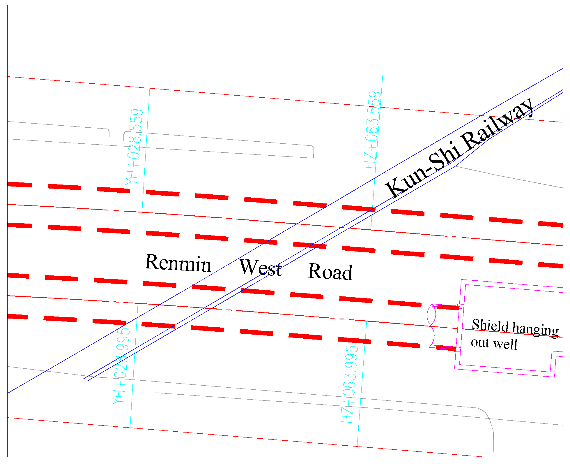
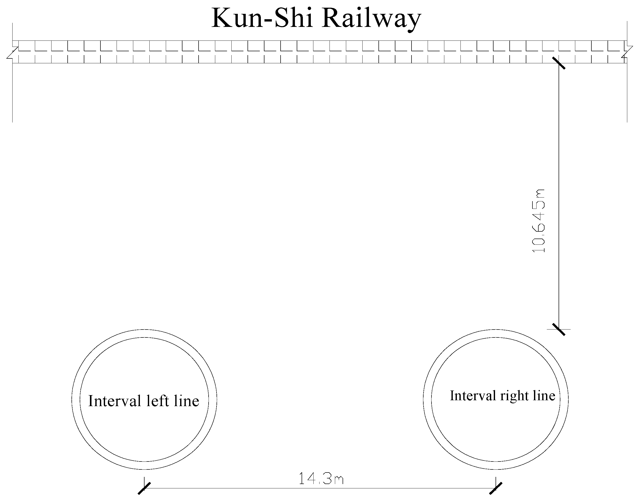
16] shield machines of φ 6.34 m were used for tunneling in the west section of Mianshan Station-Shagouwei Station-Xiyuan Lijiao Station section of Kunming Rail Transit Line 3. The normal line spacing was 13.4 m. The tunnel lining was designed with an external diameter of 6.2 m, internal diameter of 5.5 m and ring width of 1.2 m. The shield crossed beneath the Kun-Shi Railway in the section of YCK9 + 030–060.
This project started from the Mianshan Station near the Dian Ren Association south of Renmin West Road and advanced towards the east along Renmin West Road. The section of YCK9 + 030–060 crossed the Kun-Shi Railway by 34° through the crossing of Renmin West Road and Changyuan Middle Road to the Shaweigou Station near the Yunnan Ruidian Economic and Trade Co., Ltd. Both shield machines were transferred at the Shaweigou Station. Starting from the end well in the east of Shaweigou Station, the two shield machines advanced towards the east along the Renmin West Road and passed Dongjiagou and Haiyuan River course, finally arriving at the Xiyuan Lijiao Station near Lianyuan Filling Station.
The central section of the railway through which the shield tunneled was YCK9 + 032. The section within 30 m before and after the junction of the railway and tunnel was affected by the construction with about 10 days of shield crossing. The shield machine tunneled through the left line from 1 February to 10 February and tunneled through the right line from 1 March to 10 March at a low speed. The relationship between the shield tunnel and Kun-Shi Railway is shown in
Figure 1 and
Figure 2.
2.2. Geological Conditions of the Railway Region
The surface layer affected by the project along the line was plain filling soil, composed of Quaternary (Q4al + l) mud clay, clay, silty clay, silty sand and peaty soil at the upper part, Quaternary (Q3al + l) clay, silty clay, peaty soil, silty soil, silty sand and medium sand at the mid-lower part. The overlaying layer was more than 50 m thick. The soils of each layer showed multiple crossed tailing-out settlement, with great variation of burial depth and thickness as well as uneven mechanical properties. The soils within the exploration depth can be divided into:
(1-1) miscellaneous fill, including the roadbed fill and soil fill, loose to slightly close;
(2-1) silty clay, plastic, the basic bearing capacity of the soil is 135 KPa;
(4-2) organic soil, flow to the soft plastic, the basic bearing capacity of soil is 50 KPa;
(4-3) clay, plastic, the basic bearing capacity of the soil is 120 KPa;
(4-3-1) clay, soft plastic, the basic bearing capacity of the soil is 90 KPa;
(4-4-1) silty clay, the basic bearing capacity of the soil is 100 KPa;
(9-3) silty clay, plastic, the basic bearing capacity of the soil is 135 KPa;
(9-4) peat soil, plastic, the basic bearing capacity of the soil is 80 KPa;
(9-6) powder sand, slightly to medium density, the basic bearing capacity of the soil is 180 KPa;
(12-1) silty clay, hard to plastic, the basic bearing capacity of soil 150 kPa.
2.3. Overview of the Shield Machine
Two Komatsu single-circular mudding type earth-pressure balanced shield machines of φ 6.34 m were used in the section. The shield machine is mainly composed of shield housing, excavation mechanism, thrust mechanism, dump mechanism, assembly mechanism and accessory devices. It can be widely used for construction under the geological conditions of alluvial clay, diluvial clay, sandy soil, sand, gravel and pebble without separation devices and more area. The overlaying soil can be relatively thin when it is used for construction. The construction of the earth-pressure balanced shield can effectively control the uplift and settlement of the ground surface and has been widely applied in many subways in China.
As the monitoring system mounted on the shield machine adopts the world’s latest PLC control technology, sensor technology, automatic fault detection system and anti-misoperation system, the shield machine can achieve a clear monitoring picture, easy operation, accurate and fast data collection and processing as well as remote construction information transfer, so the central control room on the ground can keep track of the operation of shield machines. The shield machine adopts the measurement and guidance system integrated with target, total station, PLC and computer for simple, intuitive and accurate operation.
3. Key Construction Technology
3.1. Analysis of the Technical Difficulties
When a subway tunnel crosses underneath a railway, mutual impact would occur between the subway and the railway. The ground surface settlement during the shield construction would affect the safety of railway operation while the dynamic load of the railway would affect the safety of the subway structure [
17]. The impacts are described as follows:
- (1)
When the shield machine passes under the railway, the soil mechanical properties would be greatly disturbed, resulting in uneven ground surface settlement which would produce gaps, dislocation, steps and bevels at rail joints, seriously affecting the safety of train operation.
- (2)
When a train is running, the dynamic stress which it produces on the subgrade soil gradually decreases with the depth. The degree of the decrease is related to the mechanical properties of soil and dynamic load of the train. Generally, the depth which dynamic stress can reach is about 4–7 m. However, when there is a structure underneath the subgrade, the propagation of dynamic stress is increased.
- (3)
Shield construction leads to track settlement and irregularity, which increases the impact force between the wheel and rail, so the dynamic stress in the subgrade and soil dynamic load are increased; thus, the load applied on the subway tunnel segment is increased, affecting subway tunnel safety.
- (4)
The increase in the travel speed of trains on the Kun-Shi Railway would also lead to an increase of dynamic load of the train, which inevitably leads to the increase of dynamic stress of the subgrade surface.
3.2. Reinforcement Measures
According to the results of risk assessment [
18], grouting pipes were required to be embedded in the affected region of the railway (within 15 m mileage before and after track central line and 3 m beyond the outline of section tunnel) before the shield crossing. Then the shield advanced to the region, pre-grouting was performed through the grouting holes of the head of the shield machine and tracing grouting was performed through the grouting holes reserved on the ground according to the railway monitoring values. Under the guarantee of the above measures, the shield continued to advance and cross the railway region.
3.2.1. Reinforcement Scheme
During the shield construction, when the shield machine head reached the affected region of Kun-Shi Railway (YCK9 + 030), grouting was performed for reinforcement (reinforcement by double grouting with construction mix proportion of cement grout:sodium silicate =1:1) through the grouting holes reserved at the machine head. After each segment was assembled, grouting was performed and its volume was adjusted according to the monitoring data.
3.2.2. Reinforcement Region
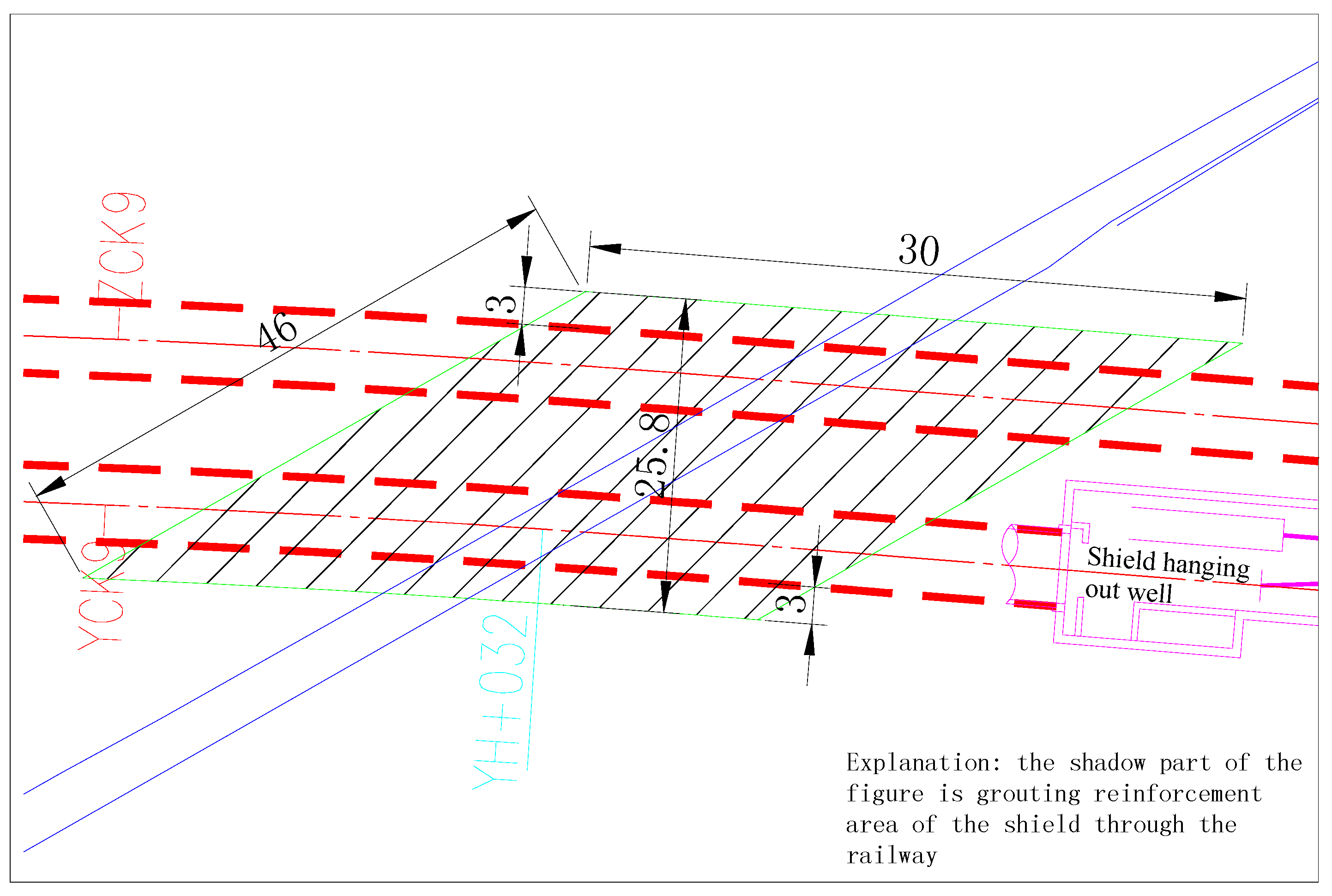
The shield machine tunneled beneath the section of YCK9 + 030–060 between Mianshan Station and Shaweigou Station of the Kun-Shi Railway; the site which the shield machines crossed was located at the Renmin West Road, crossing the Kun-Shi Railway by 34°, with about 11 m of overlaying layer. The reinforcement region is shown in
Figure 3 on the layout of reinforcement region where the shield crossed underneath the railway.
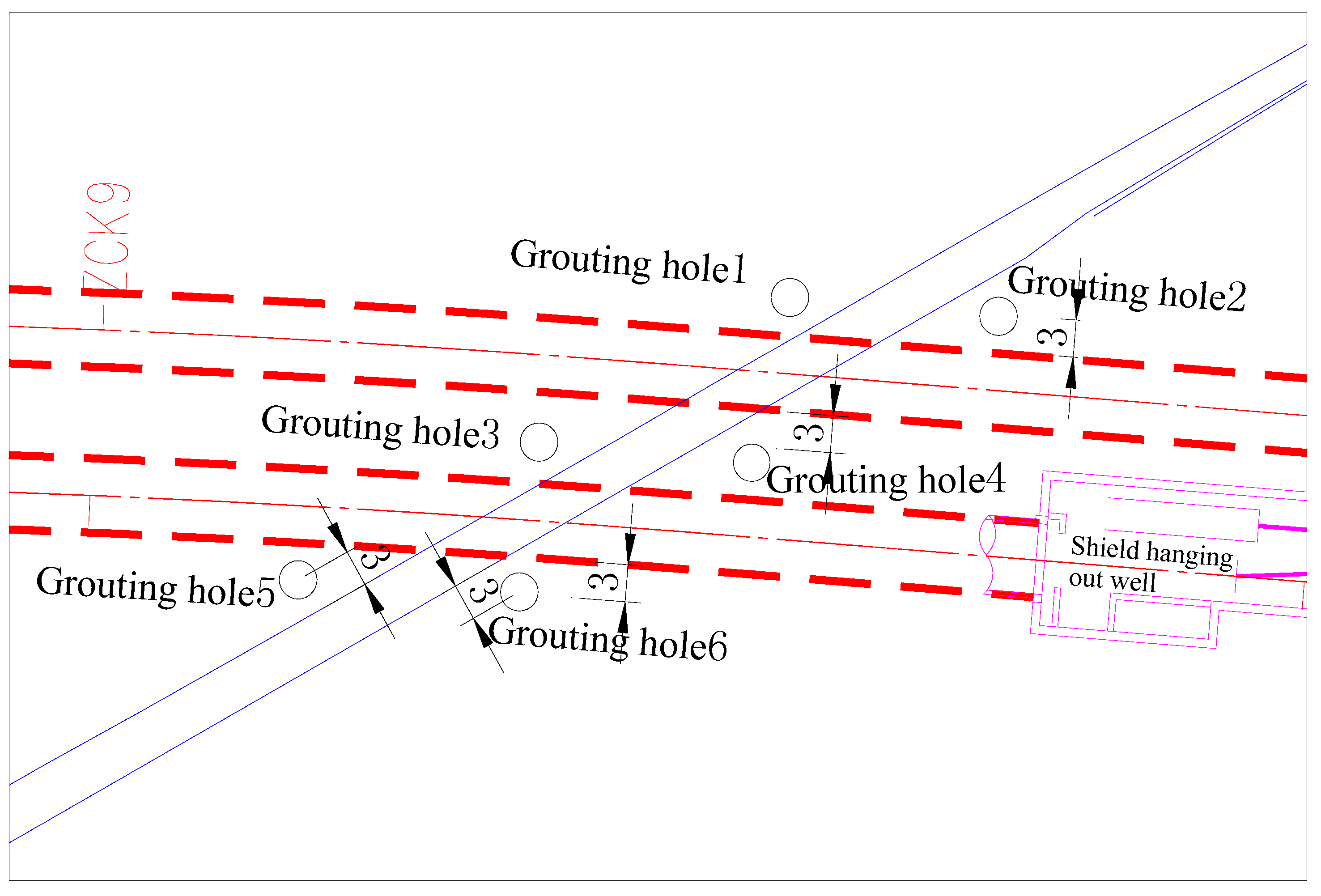
3.3. Tracing Grouting
Before the shield crossed beneath the region, six grouting holes were drilled in the ground. Along the direction of shield tunneling, grouting holes were arranged at the position 3 m away from the railway. In the direction vertical to the tunnel, grouting pipes were arranged 3 m away from the outside of the tunnel. Grouting pipes were 5 m deep under the ground. The layout of grouting holes is shown in
Figure 4.
Grouting holes were drilled and grouting pipes were laid in the ground prior to shield construction according to the layout of grouting holes. When the shield advanced within the area of the railway line, construction parameters were selected according to the monitoring results on the ground. Double grouts were used for tracing grouting. Grouting volume and parameters were adjusted and the values of uplift and settlement of track face were monitored in real time.
3.4. Measurements for Shield Construction
The key to the reduction of the shield construction’s disturbance of the surrounding soil was to maintain the stability of the shield excavation face and to ensure timely filling of the tail void when the segment left the shield tail. The stability of the excavation face of the shield tunnel was controlled by optimizing the excavation parameters and the filling of the tail void was achieved by synchronous grouting and secondary grouting. To ensure the safety and successfulness of crossing the Kun-Shi Railway, the following measures were taken:
- (1)
Monitoring points were arranged in advance in the affected region of the railway. Shield construction test sections were set and construction parameters of shield advance speed, cutter rotation speed, earth chamber positive pressure, excavated volume and synchronous grouting volume were adjusted.
- (2)
Earth pressure values at rest were set at reasonable levels. The set values of balanced earth pressure for construction were reasonably adjusted according to shield buried depth, current soil conditions, tunnel construction of previous test section and monitoring data. Excavated volume was strictly controlled and excessive or inadequate excavation was avoided. Excavated volume was reasonably adjusted according to the monitoring results on the ground and in the tunnel and adjusted according to the data. The soil loss due to excavation was controlled within 5‰.
- (3)
Advance speed was strictly controlled and adjusted. The shield machine slowed down when it reached the site 30 m away from the railway. The advance speed was controlled at around 4–5 cm/min. The shield machine slowed down again when it reached the site 20 m away from the railway. The advance speed was controlled at around 3–4 cm/min. During the crossing construction, construction data were analyzed and summarized in a timely manner to determine new parameters to guide the construction.
- (4)
The shield construction axis was strictly controlled. Changes in shield posture should not be too large and frequent to reduce the loss of soil and disturbance to the surrounding soil. The deviation of the shield advancing axis should be controlled within ±20 mm. Before the shield machine crossed the region, the shield postures were perfectly adjusted. An automatic measuring system of shield posture was adopted for automatically measuring the deviation of shield postures every 20 cm to send the measurement data to the axis control system in a timely manner so as to ensure that the shield could successfully cross the railway.
- (5)
Shield rectification was strictly controlled. Operators of the shield machine strictly executed the instructions and corrected the initial small deviations in a timely manner to prevent the shield machine from advancing in a serpentine way. They controlled the correction amount within a limit range each time to reduce the disturbance to stratum and create good conditions for segment assembly. The deviation of the shield advancing axis was corrected by adjusting the shield jacks: we decreased the operating pressure of the jacks in the place opposite the direction of deviation resulting in a path difference between the jacks in two regions so as to correct the deviation. The correction of the shield’s serpentine advancing was slowly performed in a long distance with one correction of less than 3 mm.
- (6)
Synchronous grouting volume and quality were strictly controlled. For synchronous grouting, the voids between tail segment and soil could be filled in a timely manner to reduce the soil deformation during construction. Grout which can be hardened was used with consistency of 9.5–11.5 cm. Grouting pressure and volume were controlled based on the dynamic monitoring data when tunneling. Grouting volume was adjusted based on the monitoring of the railway tunnel. Preliminary grouting volume should be 3.0 M3/ring. Grouting pressure should be reasonably controlled to perform filling rather than splitting. The soil layer outside the segment would be disturbed by grout due to large grouting pressure, resulting in great settlement and grout loss; small grouting pressure would lead to slow filling. Large deformation would also be caused by inadequate filling. Grouting pressure should be controlled by 1.1–1.2 times earth pressure at rest.
- (7)
Segment assembly was strictly controlled. The jack was used as much as possible for segment assembly and was not allowed to stand idle. The jack was retracted as little as possible after shield tunneling to meet segment assembly so as to prevent the jack from retraction and disturbance to soil. The jacking force of the jack was adjusted in a timely manner after segment assembly to prevent abrupt changes in shield posture.
- (8)
In order to prevent groundwater and synchronous grout from rushing into the tunnel from the shield tail during the shield’s advance, grease was applied onto the wire brush of the shield tail to ensure that the voids between shield tail and segment were filled with grease during construction to seal the shield.
- (9)
Secondary grouting was performed in a timely manner to control the post-construction settlement. After shield crossing, the long-term tracing grouting was conducted in a timely manner on the soil surrounding the tunnel beneath the railway section crossed by shield according to the monitoring of the tunnel and ground track.
3.5. Monitoring Scheme
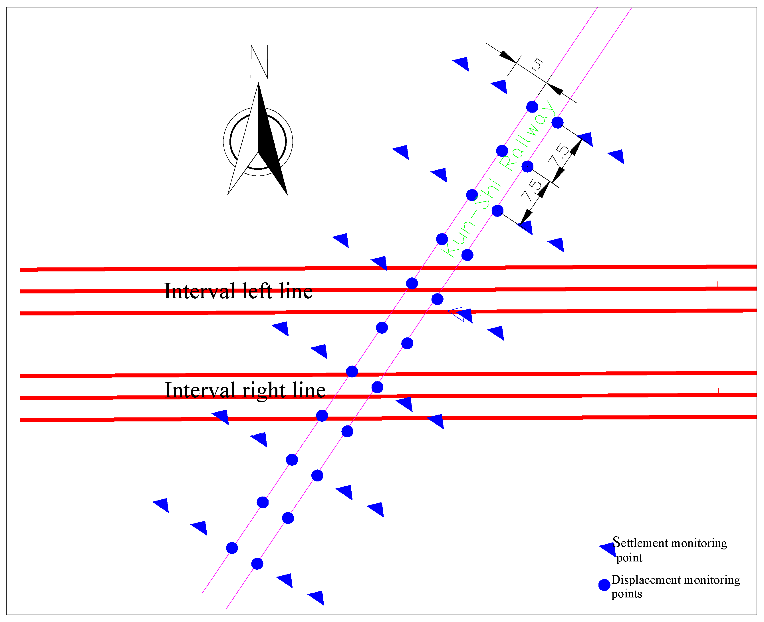
3.5.1. Arrangement of Monitoring Points
Monitoring points of settlement and displacement were arranged along both sides of the railway subgrade according to the layout in
Figure 5; four rows of settlement monitoring points were arranged along the direction of the shield’s advance with a row spacing of 5 m and a line spacing of 15 m; two rows of displacement monitoring points were arranged on the rail in the direction of the shield’s advance with a line spacing of 7.5 m; a precision level instrument was used for settlement monitoring and a total station instrument was used for displacement measurement.
3.5.2. Control Standards
(1) Monitoring accuracy
The monitoring accuracy is shown in
Table 1.
(2) Monitoring and controlling indexes
According to the design requirements, the settlement of ground surface and national track face caused by the shield’s crossing railway was controlled within ±10 mm. The height difference between two tracks of each railway line was not greater than 4 mm. At the same time, 70% of the above limit values were taken as the values for the monitoring alarm.
3.5.3. Monitoring Content
(1) Ground surface settlement
Nine monitoring sections of ground surface settlement were respectively set at both sides of the railway line where the shield crossed underneath, along the vertical direction of the shield’s advance.
(2) Track settlement
Deformation monitoring points were first arranged on the ground prior to the shield’s advance. Five monitoring sections (one section was set in the centers of railway line respectively and one section was set at the edge of the track bed on either side of the railway line) of transverse settlement were set in the crossed region; the monitoring points on the monitoring section of transverse settlement were arranged in the same way as the ground surface settlement.
(3) Uneven settlement between rail face
Monitoring points of settlement were arranged on the rail face corresponding to the section in the region affected by construction.
3.5.4. Monitoring Method, Technical Requirements and Monitoring Frequency
(1) Leveling survey
Settlement monitoring was conducted according to the national Grade II leveling specifications. Two or three bench marks were set at about 100 m beyond the construction region at the beginning of the reckoning. Each monitoring point and bench marks formed a closed or annexed leveling line. The average of the two measured values was taken as the initial leveling value. An S1 (Geodetic level) level instrument was used for measurement with a per kilometer round-trip error (accuracy) of less than or equal to 1 mm. This is mainly used for the national secondary level precision leveling measurement.
(2) Measuring method
A precise level instrument was used for the measurement. Initial leveling measurements were acquired jointly at working bench marks and bench marks nearby. Each tolerance should be strictly controlled when monitoring. The tolerance at each monitoring point should not exceed 0.5 mm. One monitoring station should have fewer than three monitoring points which were not on the leveling line. If exceeded, the measurements at post monitoring should be accented for verification. Monitoring should be conducted twice at the monitoring point for the first time. The difference between the two leveling values should be less than ±0.1 mm and the average should be taken as the initial value.
(3) Uneven settlement between rail face
1) Monitoring point embedment
Monitoring points of the rail face were set in the bolt shaft of the rail fastening.
2) Measuring method
Uneven settlement between the rail face was determined through level measurement.
3.5.5. Monitoring Frequency
All monitoring points were observed when the shield advanced to the site 30 m away from the railway for collecting original values. When the shield advanced to the site 20 m away from the railway, monitoring was continuously conducted. The monitoring frequency was required to be adjusted again after the shield crossed underneath according to the changes in measurement data. The monitoring frequency of the shield’s crossing railway is shown in
Table 2.
4. Conclusions
In this paper, the key technology of the construction of a shield tunnel crossing a railway is described in detail within the context of Kunming Rail Transit Line 3 crossing the Kun-Shi Railway. The shield crossed Kun-Shi Railway safely because the process followed these methods: (1) reinforcing the stratum of the region crossed by the shield in advance to achieve high stability; (2) accurately setting the front earth-pressure and controlling the driving speed; (3) strengthening synchronous grouting, reasonably controlling grouting quantity and the quality of grouting; (4) setting the parameters of shield tunneling by monitoring data, maintaining information construction; (5) strengthening the shield tail seal; (6) controlling shield tunneling attitude, gently rectificating, minimizing the disturbance of the front and the surrounding soil by shield tunneling.
Monitoring data shows that, during the period of reinforcement, the maximum cumulative uplift on the railway line was 2.2 mm; during the period of shield crossing, the maximum cumulative uplift on the railway line was 3.1 mm, the maximum settlement was 4.3 mm and the maximum single settlement was 1.2 mm. Seen from the construction process control and monitoring results, the use of appropriate construction parameters after stratum reinforcement could control the uplift and settlement of the rail face within a 5 mm range, far smaller than the alarm values. After the shield crosses the railway, according to the late settlement, secondary grouting must be carried out in time to control the late settlement.
Acknowledgments
We extend our gratitude to the National Natural Science Foundation, China (51374012), Anhui Province Science and Technology Project, China (1501041123). Those supports are gratefully acknowledged.
Author Contributions
Jinjin Ge wrote the manuscript. Ying Xu provided guidance and suggestions. Weiwei Cheng provided related pictures.
Conflicts of Interest
The authors declare no conflict of interest.
References
- Liu, J.H.; Hou, X.Y. Shield Tunnel; China Railway Press: Beijing, China, 1991. (In Chinese) [Google Scholar]
- Qian, Q.H. Meeting the development climax of urban underground space in China. Chin. J. Geotech. Eng. J. 1998, 20, 112–113. (In Chinese) [Google Scholar]
- Japanese Civil Society; Liu, T.X., Translators; Standard Specification and Explanation of Japan Tunnel; Southwest Jiao Tong University Press: Chengdu, China, 1993. (In Chinese)
- Gao, B.L.; Ren, J.X. Safety risk assessment for adjacent underground pipelines in metro construction. Mod. Tunn. Technol. J. 2016, 53, 118–123, (In Chinese with English abstract). [Google Scholar]
- Masahiro, M.; Kotaro, K. Use of compact shield tunneling method in urban underground construction. Tunn. Undergr. Space Technol. J. 2005, 20, 159–166. [Google Scholar]
- He, C.; Feng, K.; Fang, Y. Review and prospects on constructing technologies of metro tunnels using shield tunnelling method. J. Southwest Jiaotong Univ. J. 2015, 50, 97–109, (In Chinese with English abstract). [Google Scholar]
- Desmond, T.D. Henry Marc Brunel: The first submarine geological survey and the invention of the gravity corer. Mar. Geol. J. 1967, 5, 5–14. [Google Scholar]
- Nick, M.; Mike, B. Tunnel vision? Brunel’s Thames Tunnel and project narratives. Int. J. Proj. Manag. J. 2013, 31, 692–704. [Google Scholar]
- Guo, H.Y.; Gu, Z.W. Construction technique for tunnel excavation with large TSM under Huhang railway line. Build. Construct. J. 2006, 28, 767–768, 771, (In Chinese with English abstract). [Google Scholar]
- Liu, Y.C. Tunnel boring across underneath high-speed rail ways by shield machines. Tunn. Construct. J. 2006, 26, 47–49, (In Chinese with English abstract). [Google Scholar]
- Zhang, S.R.; Tian, X.X.; Wang, G. 3D numerical simulation of excavation of shield tunnel in softground. Chin. J. Undergr. Space Eng. J. 2012, 8, 807–814, (In Chinese with English abstract). [Google Scholar]
- Ye, Y.D.; Ju, J.; Wang, R.L. Discussion on construction technology during passing of shield through the operating metro tunnel. Construct. Technol. J. 2005, 34, 67–68, (In Chinese with English abstract). [Google Scholar]
- Guo, M. Influencing factors and control technologies for ground surface settlement induced by shield tunneling when shield bores slowly/shield stop. Tunn. Construct. J. 2016, 36, 701–708, (In Chinese with English abstract). [Google Scholar]
- Peng, B.; Yang, Z.Y. Construction application of shield tunnel through railroad group. J. Maoming Univ. J. 2007, 17, 74–77. (In Chinese) [Google Scholar]
- Liu, J.H. Numerical simulation of surface settlement caused by soil pressure in shield-tunneling. Tunn. Construct. J. 2007, 27, 30–32, (In Chinese with English abstract). [Google Scholar]
- Zhang, Q.; Hou, Z.D.; Huang, G.Y. Mechanical characterization of the load distribution on the cutterhead–ground interface of shield tunneling machines. Tunn. Undergr. Space Technol. J. 2015, 47, 106–113. [Google Scholar] [CrossRef]
- Hu, Z.; Shao, X.; Yao, H.Y. Mechanics analysis of shield construction traversing adjacently under existing urban tunnel. J. Sichuan Univ. (Eng. Sci. Ed.) 2016, 48, 52–59, (In Chinese with English abstract). [Google Scholar]
- Zhang, J.; Jia, M.C.; Zhang, J. Analysis of risks in overall process during the construction period of metro shield tunnel construction. Highw. Eng. J. 2013, 38, 38–56, (In Chinese with English abstract). [Google Scholar]
© 2016 by the authors; licensee MDPI, Basel, Switzerland. This article is an open access article distributed under the terms and conditions of the Creative Commons Attribution (CC-BY) license (http://creativecommons.org/licenses/by/4.0/).


