Structural Behavior of the General Archive of the Nation (AGN) Building, Mexico

Instituto de Ingeniería, Universidad Nacional Autónoma de México, México City 04510, Mexico
*
Author to whom correspondence should be addressed.
Infrastructures 2018, 3(3), 39; https://0-doi-org.brum.beds.ac.uk/10.3390/infrastructures3030039
Submission received: 27 July 2018
/
Revised: 8 September 2018
/
Accepted: 10 September 2018
/
Published: 18 September 2018
(This article belongs to the Special Issue Selected Papers from the REHABEND 2018 Congress)
Abstract
:This article presents a study on the structural behavior of the Government Building that is part of the old Lecumberri Palace and which currently houses the Mexican General Archive of the Nation. This building was inaugurated in 1900 and closed in 1976, after serving as a prison for 76 years. It was reopened in 1982 after it had undergone several remodeling works. The construction is made of brick masonry with lime mortar. It is supported by a deposit of overly compressible high-plasticity clays. The main problems of this building are the appearance of cracks in both interior and exterior walls, and moisture in the ground floor, caused by differential settlements. The study entailed a geometric and a damage survey as well as ambient vibration tests in order to determine the dynamic properties of the construction. The data obtained was used for the making of a model that, using the finite element method, was analyzed under different load conditions. This study has focused on the overall response with the assumption of smeared crack damage. According to the results, the building’s safety was deemed as acceptable. It has the capability to withstand seismic actions as established by the Mexican Building Code due to the high density of its walls and the resulting stiffness, which infer that the fundamental vibration period of the building would be distant from the predominant vibration period of the soil. This highlights the idea that the building’s critical condition is constituted by the differential settlements, which cause damage in the construction.
1. Introduction
The General Archive of the Nation is located in what once was the Lecumberri Palace Prison, north-east of Mexico City, in Mexico. It is formed by galleries, cells, yards and the Government Building which were adapted in order to safeguard the historical archive of the nation. However, in recent years, it began to show signs of obsolescence: in addition to lacking the necessary facilities to provide the ideal environmental conditions; it was already saturated with files and archives. As a result, a new building was built to relocate the archives of the nation that were kept in the old building of the General Archive of the Nation [1]. The main objective is to preserve the historic memory of Mexico in optimal conditions, both physical and environmental.
For this reason, the authorities, concerned for its preservation as a historic building, requested information about its current state. To this effect, a study on the structural behavior of the Government Building (which is part of the old construction and functioned as an administrative body) was carried out. This study was made through the gathering, reviewing, and processing of the available information about the building. Special attention was paid to the information regarding the structure, which shed light on the specific characteristics of its original state, and the works and interventions to which it was subjected over time. Plans of the construction when it took place were not available, so surveys on its geometrical configuration were performed. The level use was also surveyed in order to identify the acting loads on the structure and thus generate the correspondent planes. There was also a damage survey, which entailed a field inspection of the structural elements.
Once all the information was gathered, finite element numeric models were developed with the commercial software SAP2000 [2]; these models allowed the evaluation of the building’s structural behavior based on the Mexican Building Code [3]. An analysis for differential settlements was carried out because they are the main trouble of the construction.
2. Historical Background
The project to build Lecumberri Palace was born as a result of the reform to the Penal Code in 1871 [8] which contemplated the construction of a jail. It was developed by architect Antonio Torres Torija, and engineers Antonio M. Anza and Miguel Quintana were in charge of the construction; it was inaugurated on 29 September 1900, during the mandate of President Porfirio Díaz. It continued to be a prison until 1976.
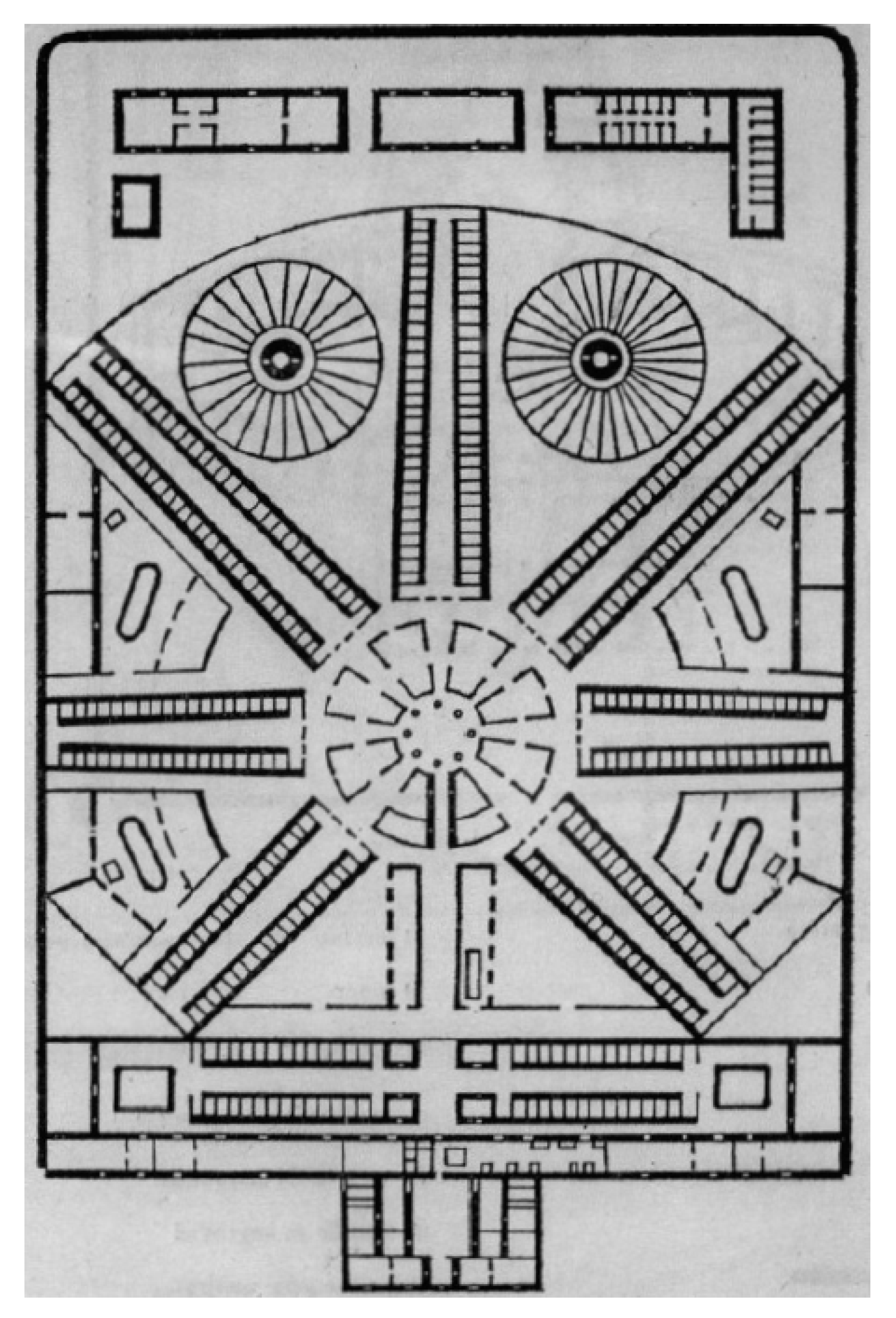
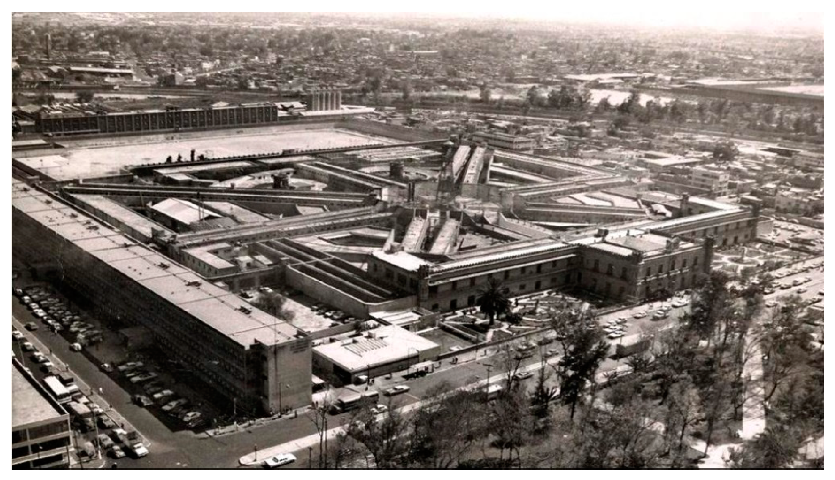
The project for the mighty prison was developed according to the Panopticon, an architecture for correctional facilities from the 19th century. It consists of a rotunda from which rows of rooms emerge in a radial manner. A 35 m surveillance tower stood at the center. The administrative offices were in the Government Building, which was in perpendicular axis to the central axis of the compound. It was all surrounded by a perimeter wall (Figure 1 and Figure 2).
The evolution of the jail system made the Lecumberri Palace non-functional. By 1971, the construction was insufficient; its original capacity of 996 inmates was surpassed with an approximate population of 3800 prisoners. During the presidency of López Portillo (1976–1982), new jails were opened. This allowed the Lecumberri Palace to be vacated.
The building was to be demolished but in 1977, by a presidential decree, it became the home of the General Archive of the Nation. The objective was to concentrate the entirety of the scattered nation’s files and archives in a sole place, thus unifying the control, information and conservation of the national heritage.
The remodeling works lasted 5 years and architect Jorge L. Medellín was responsible for them. A fundamental part of the project was the preservation of the original structure; therefore, a “recycling” technique was used: restoration occurred only where it was necessary. Thus, the main restoration process involved the demolition of walls, dismantling of the bars, the rows of the rooms’ roofs, the fixing and plastering of the main façade and interior wall’s stone frames, the creation of the central cupola (an acrylic dome), and the creation of a new row of rooms that connects the government building and the interior of the compound.
The walls of the rows of rooms and the Government Building were saved. These were made of unreinforced brick masonry and only visible damage was fixed. The new elements such as roofs and supports for new structures were made of new materials (e.g., reinforced concrete).
The General Archive of the Nation was inaugurated on 27 August 1982. This project contemplated the necessary space for the archives and government services: library, news library, map library, microfilming, cubicles for researchers; bookbinding, conservation and document-reproduction workshops; and diffusion areas, which include a congress, exhibition and reproductions sales unit. Criticism of the precinct’s inadequacy for archival safeguarding followed. Moreover, there was flood risk due to the difference in level from the street level (Figure 3), and its closeness to the main drainage channel promoted the presence of pollutants that cause paper damage.
According to the historical archive on the webpage of the AGN (General Archive of the Nation) [11], the School of Architecture of the National Autonomous University (UNAM) conducted a study on the building’s condition in 1998. The study reported that the structure was damaged as a result of its heterogenous constructive system (masonry), which was partly a consequence of the works made in the 1980s that meant a change in both the geometry and the load distribution in order to make it adequate for its newly designated purpose. Additionally, it is located in a high resonance area in the case of an earthquake, differential settlements are constant due to the high soil compressibility, and, finally, the environmental conditions are not within the appropriate ranges. On the other hand, the Engineering Institute of UNAM reported in 1999 that Lecumberri Palace was built on a deposit of highly compressible clays, which is the reason why the building has suffered deformation and differential settlements since its construction.
After several studies, reports and opinions on the situation of the General Archive of the Nation, it was decided to develop a project that included remodeling and the construction of a new building in the same area. The new building would be located on the former offices of the National Population Registry (RENAPO), which were to be demolished. The project considered two stages: the first one consisted of the elaboration of an executive project, along with expert studies such as the development in regard to the urban and environmental impact, the demolition of the National Population Registry, and the restauration of the Government Building in the old precinct. The second stage encompassed the construction of the new building, destined to safeguard the documental archive of the nation. The study on the structural behavior of the Government Building in the old precinct falls within the first stage of the aforementioned project. The restoration work was of injections and the consolidation of cracks on walls, cleaning of the front finishes, and adaptation of both interior and exterior spaces and changes of installations.
3. The Numerical Model
In order to produce a numerical model, geometric and damage surveys of the Government Building were carried out in situ because that information was not originally available. The process for the gathering of said information is described below.
3.1. Structural and Geometric Survey
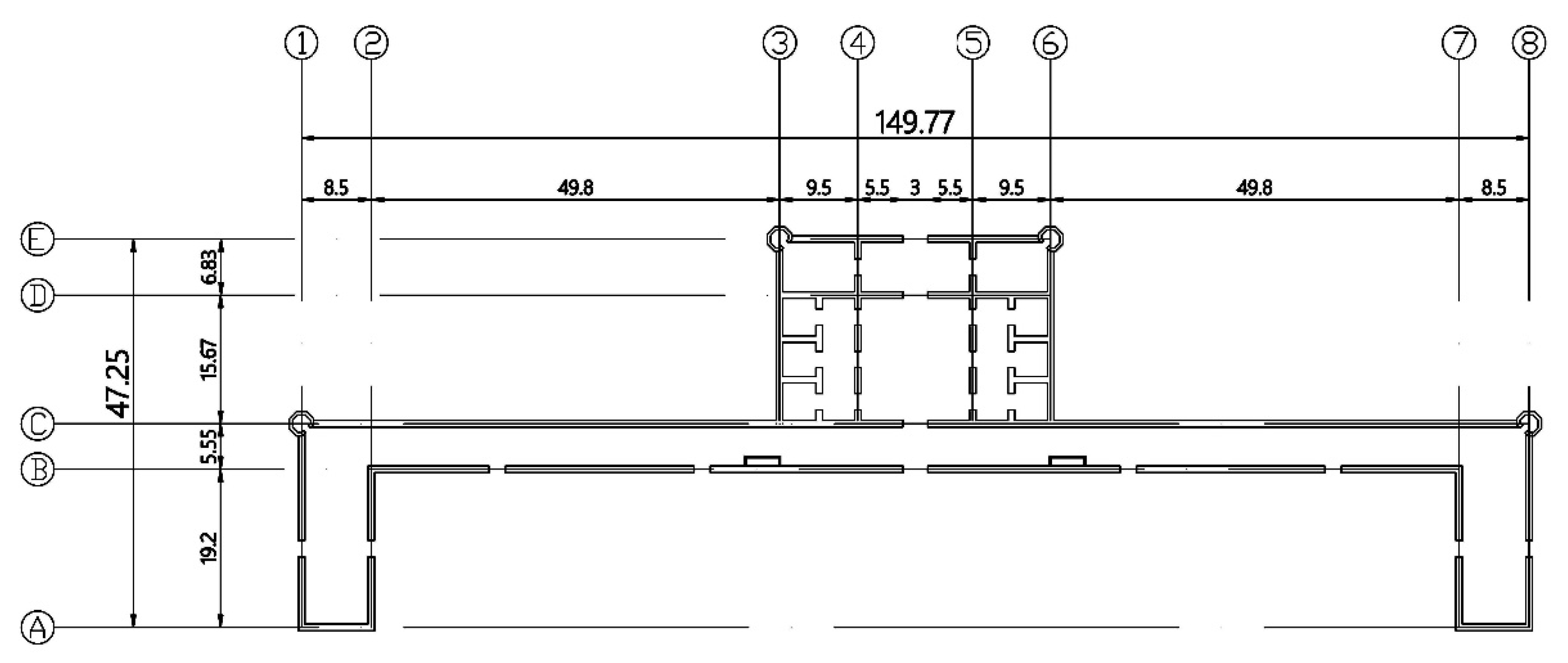
The Government Building is a solid construction with unreinforced brick masonry with lime mortar walls that are 80 cm thick. The floor is made of concrete slabs. Figure 4 shows a plan view of the Government Building. The building’s geometry is symmetrical. The building has a total of 112 windows and 8 doors and it was mainly used as offices. It has a reception and exhibition areas.
3.2. Damage Survey
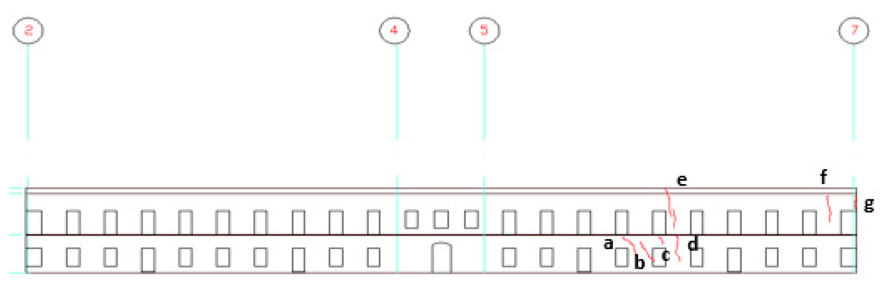
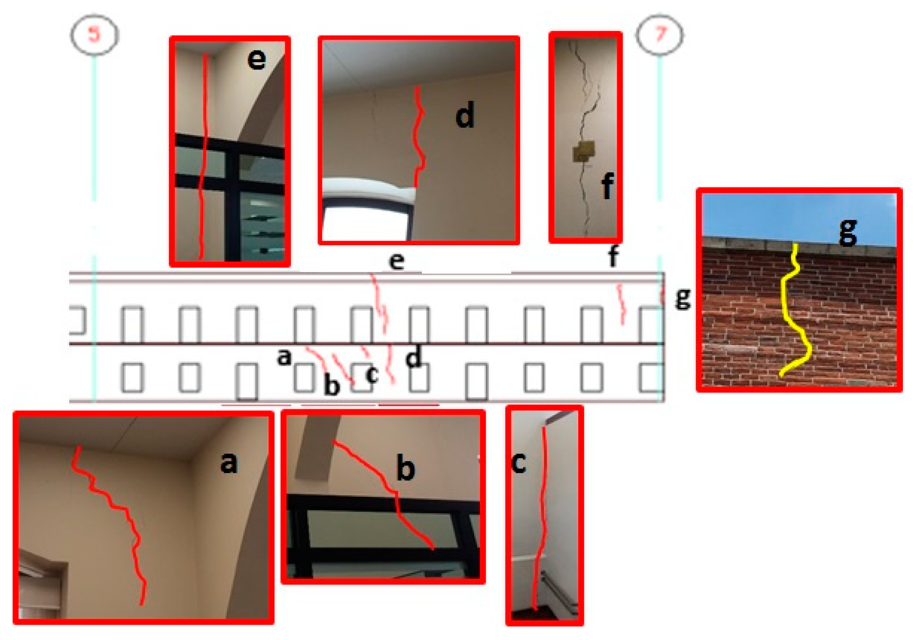
The inspection to which the building was subjected showed that it is in good condition for the most part; the south wing is the exception because it has several cracks on the walls, particularly on the ground floor. These cracks are consequence of differential settlements and some of them are major because they go along the entire height of the building (up to three meters long and five millimeters wide). However, these cracks do not jeopardize the building’s stability. There are also moisture problems on the ground floor. Figure 5 and Figure 6 show the affected areas.
Cracks in the ground floor (cracks 1 to 7 in Figure 5 and cracks a to d in Figure 6) have a similar distribution like a beam in positive flexural deformation. The cracks near the center of the building (cracks 1 to 5 in Figure 5 and cracks a to d in Figure 6) are due to tensile stresses, while cracks 6 to 7 in Figure 5 are due to shear stresses. This is due to the differential settlements being bigger at the center part and a parabolic-like deformation is presented. The bending moment due to this behavior concentrates the tensile stresses at the ground floor.
Although several cracks are present due to differential settlements, there is no physical evidence that the structure was divided into two or more smaller sub-structures. Thus, for the numerical models (see Section 3.4), the model considers the entire building.
3.3. Determining Gravitational Loads
3.3.1. Dead Load
Dead load is the one constituted by the weight of the structure, finishings (partition walls, soffits, finished floors, carpets, etc.) and installations (hydraulic, sanitary, etc.). The gathered information made it possible to determine the mechanics of the materials that could represent the ones in the building. Broadly speaking, two types of materials were used for the elaboration of the numeric model. Brick masonry with lime mortar was used for the walls and reinforced concrete was used for the slabs based on the proposal by reference [13]. Table 1 shows the mechanic properties assigned to each of the elements that are part of the numerical model of the Government Building. The loads from finishings were, for simplicity purposes, evenly distributed (strength/area). Table 2 shows the loads that correspond to finishing and installations.
3.3.2. Live Load
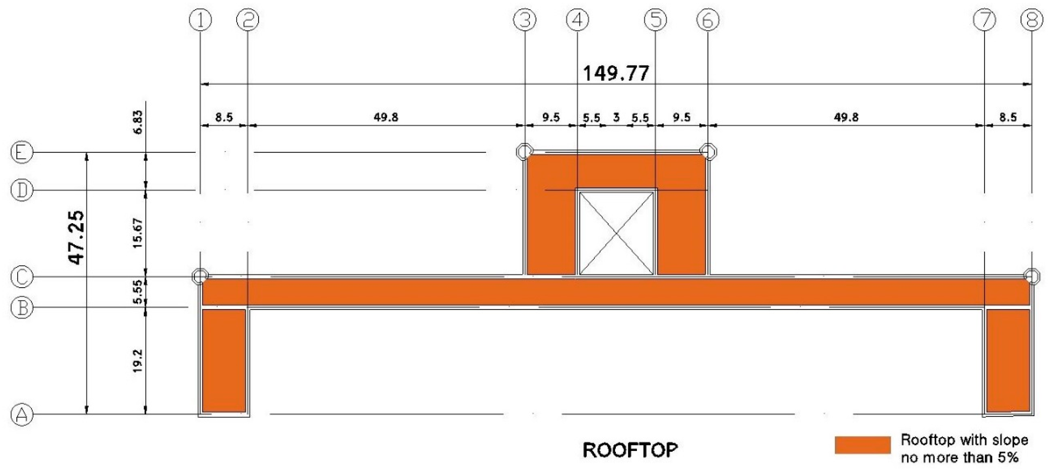
The maximum, instant and average live loads were taken from the Mexican Building Code from 2004 [14], according to each level’s use (Table 3). Based on this code, live loads will have three different values depending on the type of analysis that will be performed. Maximum live loads are used for the gravitational analysis and immediate settlements; instant live loads are used for the seismic analysis; average live loads are used for differential settlements. Figure 7 shows the distribution of floor uses.
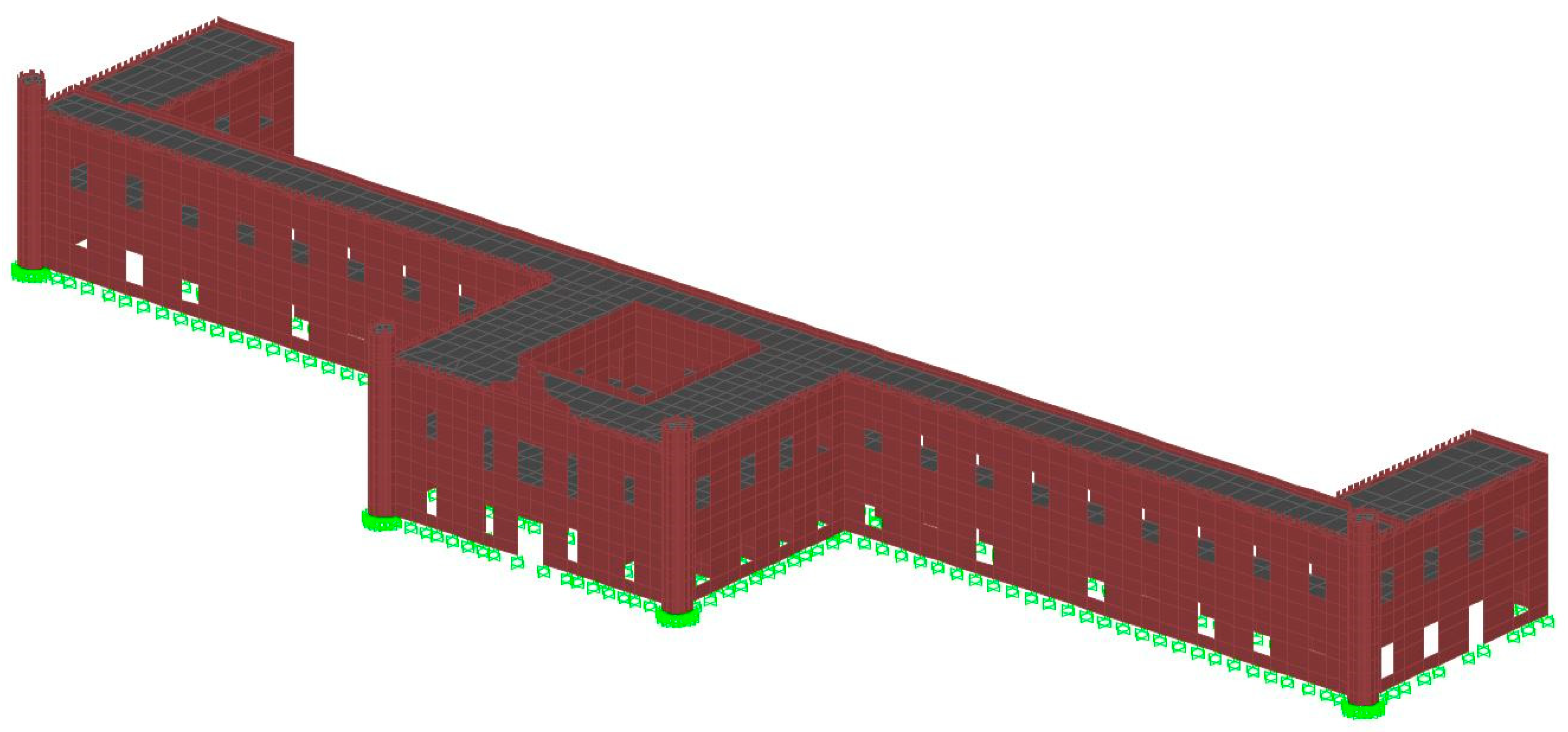
3.4. Finite Element Model
The finite element method was used to simulate the behavior of the building with the commercial structural analysis software SAP2000 ver. 19.1.0 [2]. It must be noted that this model was considered perfectly vertical and its base fully horizontal. Shell elements of four nodes were used to generate the body of the structure. These shell elements follow the Kirchhoff formulation, which neglects transverse shear deformation. Dimensions are based on the aforementioned surveys and general features: the building’s height is of 14 m, with 17 m towers, and a total longitude of 150 m. Walls are 80 cm thick, on average. It has four towers 40 cm thick and the story height is 7.04 m. The numerical model takes into consideration the different uses of each floor, which allowed the different loads (live and dead) associated with them to be defined. Each structural element was assigned its own mechanical properties based on the information about the materials of the building. The model has 5946 shell elements, 6628 nodes, and 37,536 degrees of freedom. Figure 8 shows the numerical model.
4. Results
4.1. Analysis by Gravitational Loads
The analysis by gravitational loads was performed in order to estimate whether they have induced stresses superior to the compressive strength of the material, which would cause a possible failure due to the structure’s own weight. All the live loads according to the use of the floor were considered. Table 4 shows the weights obtained from the numerical model.
The safety factor due to the own weight was of 5.3. It was obtained by the relation of the compressive strength of the masonry and the average stress at the base of the model. Likewise, the safety factor for the foundation was calculated. For this case, a value of 30 kPa was considered as the compressive strength of the clays in the Valley of Mexico. This safety factor was equal to 0.55.
These results show that the structure does not face problems from the building’s current own weight. However, the soil presents a safety factor under 1, which indicates that it is below the admissible limit in regard to the kind of soil. This explains the settlements that have been happening from the building’s construction to this day.
In order to review the displacements of the flooring system, the maximum slab displacement was compared with the maximum permissible displacement, according to the calculation of maximum slab deflection established by the 2004 Mexican Building Code [14]. As the slab can be deformed without restriction, since the partition walls inside the building do not reach the ceiling of the building, the maximum deflection allowed is of 0.5 cm plus the span of the slab divided by 240. The maximum slab displacement must take into account the long-term effect. In this way, as recommended by the Mexican Building Code, the elastic displacement obtained by the numerical analysis was multiplied by 2.
4.2. Modal Analysis
The Building Code [15] establishes that for the spectral modal analysis of any structure, the necessary number of modes must be included so that the sum of the effective weights in each direction be 90% of the total structure or higher. The numerical model of the Government Building obtained more than 90% of the sum of effective weights with 400 modes, mainly because slabs cannot be considered as stiff diaphragms. It is important to note that the slab does not behave as a stiff diaphragm because of the building’s dimension. This means that the wings of the construction are more flexible than the central part, which provokes torsions. Table 6 shows the first 4 vibration modes with their respective periods and modal shape. The first mode is transversal with a vibrating period of 0.59 s, while the first torsional mode is of 0.34 s and the first longitudinal is of 0.32 s. This indicates that the stiffest direction is the longitudinal.
4.3. Ambient Vibration Tests
In order to know the dynamic properties of the building, the Seismological Engineering Department of the Engineering Institute UNAM [16] carried out some ambient vibration tests. The equipment used consisted of two Balanced Force Accelerometers plugged into Kinemetrics data recorders, as well as three intermediate period speed sensors (T = 30) connected to GURALP recording sensors. The accelerometers were used as a reference in the free field site and the ground floor. The measurements were made in various points throughout the rooftop, the ground floor and outside the building, in the free field in order to obtain the spectrum and determine the predominant soil vibration period.
From the records of the free field, a soil period of 2.4 s was obtained; it corresponds to the seismic zone in which the structure is located according to the 2004 Building Code. On the other hand, the building does not have a stiff diaphragm, so obtaining the vibration periods was somewhat difficult. The first is within a range between 0.80 and 0.60 s, where the movement is predominantly transversal. This period is similar to that obtained by the numerical model, which is of 0.59 s. Another period that was obtained is between 0.42 and 0.40 s, which can correspond to the period of 0.38 s obtained in the third mode of the numerical model. The measurements also threw a third period that equals 0.30 s with a predominantly torsional movement. This corresponds to the fourth mode of the model that has a period of 0.34 s. Table 7 presents a summary of this information.
4.4. Modal Spectral Analysis
The General Archive of the Nation is located in seismic zone IIIc, according to the Building Code [15]. The building is classified as structure type A, which considers a seismic coefficient of 0.60 for the seismic zone IIIc (Figure 10). Moreover, a seismic behavior factor Q of 1 is considered because the structure is of unreinforced brick masonry [15].
The combination of earthquake forces in two octagonal directions is considered for the analysis of seismic behavior, 100% in one direction and 30% in a different one, as well as the structure’s own weight. The wall drifts were obtained in strategic points of the building, as shown in Figure 11. The permissible drift for unreinforced brick masonry constructions is of 0.0015 [15].
Figure 12 shows the drift results for different combinations by level. It should be noted that because the drifts are small, the abscissa axis is logarithmic. The building is very stiff in both directions so earthquake forces barely deform it. This means that drifts fall within the limits. The drift profiles are typical of two story buildings where the upper level has a bigger drift. Table 8 shows the basal shear obtained for each seismic load combination. Figure 13 shows the maps of vertical and horizontal axial stresses.
The stress maps show that the building’s behavior is similar independent of the direction of the earthquake, although the solicitations for an earthquake in a transversal direction increase. Even though the diagram’s highest stresses reach 4.9 MPa in the slab zone, they do not exceed the concrete compression resistance. Stresses for masonry elements fall within a range of 0.15 MPa to 1.3 MPa so 1.5 MPa of the masonry compression resistance is not exceeded in either case.
These results show that the structure does not have difficulties resisting seismic actions according to the Mexican Building Code. This can be mainly attributed to the building’s stiffness, which causes the structure’s period to be far from the soil’s period that is located in the ascending branch of the design spectrum.
4.5. Differential Settlements Analysis
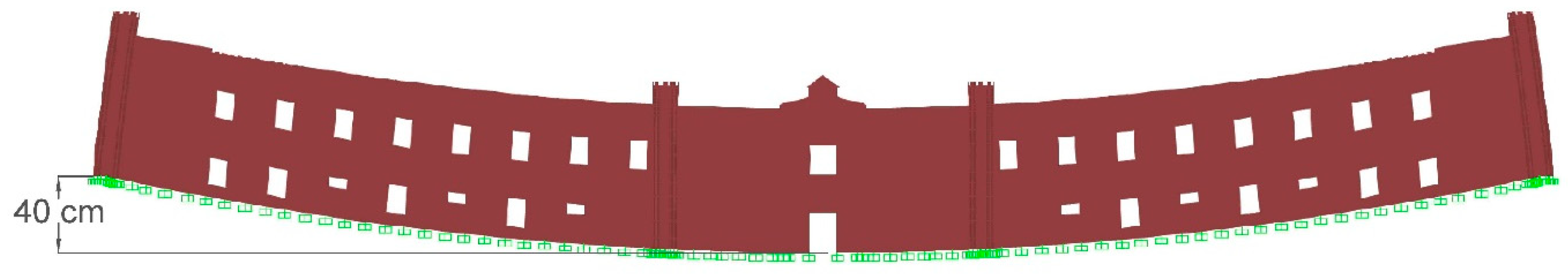
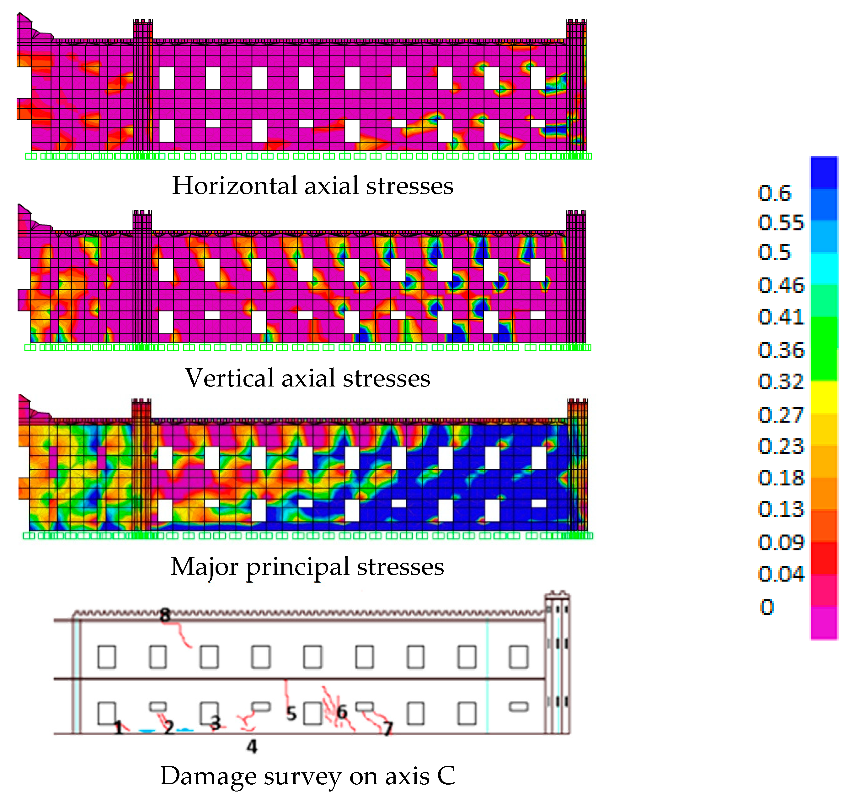
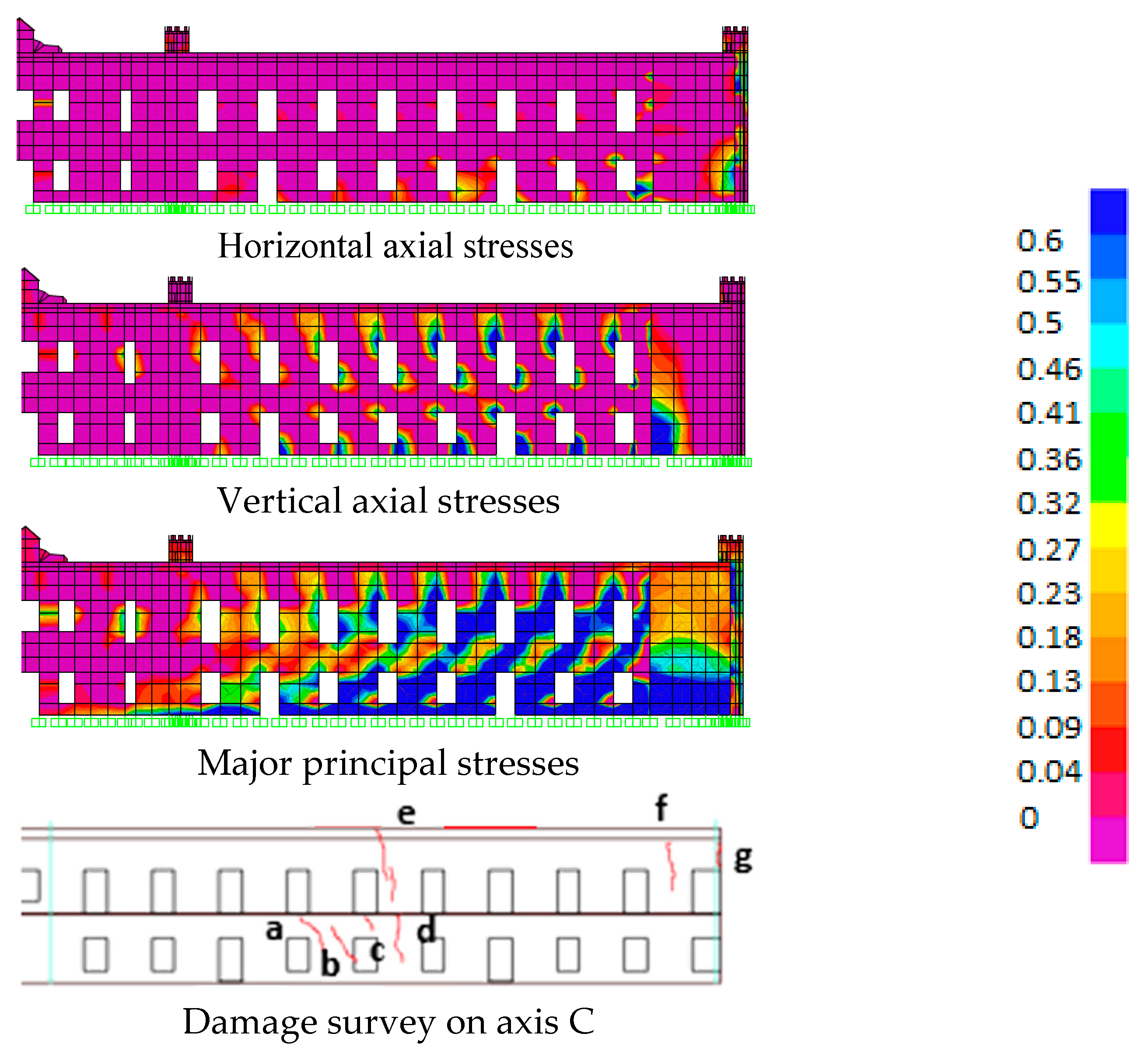
Once an acceptable result of the structure’s seismic behavior was obtained, a study on differential settlements was carried out given that those constitute the main cause for the building’s damage. Based on the information gathered in situ, due to the lack of topographical information that would provide a settlement profile, it was noted that the settlement that the building presents follows a 40 cm slope towards its central part. A pattern of parabolic settlements, as shown in Figure 14, was proposed for the representation of the aforementioned behavior. For its analysis a combination of dead load, average live load plus settlements was used [17].
These loads helped to create maps of vertical and horizontal axial stresses, and principal stresses. It can be observed that there is a stress concentration that exceeds the masonry’s tensile strength of 0.15 MPa (Figure 15 and Figure 16). This could be the reason for the existing cracks. However, the zones where there are concentration of stresses are not the same as the cracks in the real structure. Since the linear analysis does not allow a redistribution of stresses, a non-linear analysis becomes necessary.
4.6. Linear Sequential Analysis
A linear elastic analysis is a practical way to detect weak areas in a structure, as well as elements that could behave in an undesirable or non-satisfactory manner. However, it does have an enormous disadvantage: it does not redistribute stresses caused by element damage. This redistribution may cause damage in other parts of the structure [18].
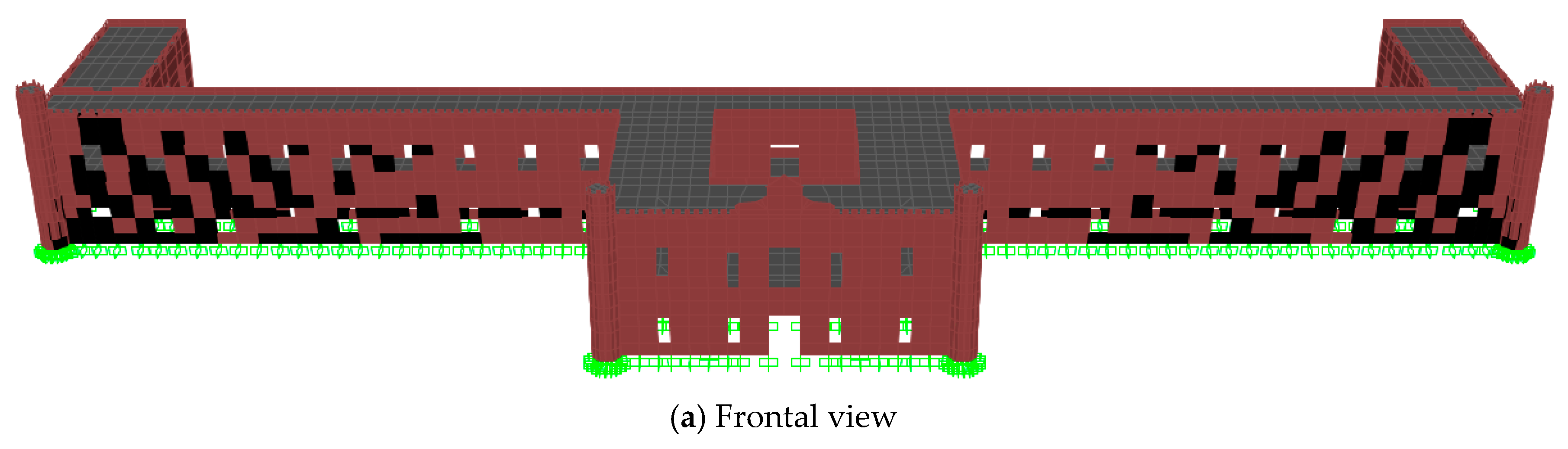
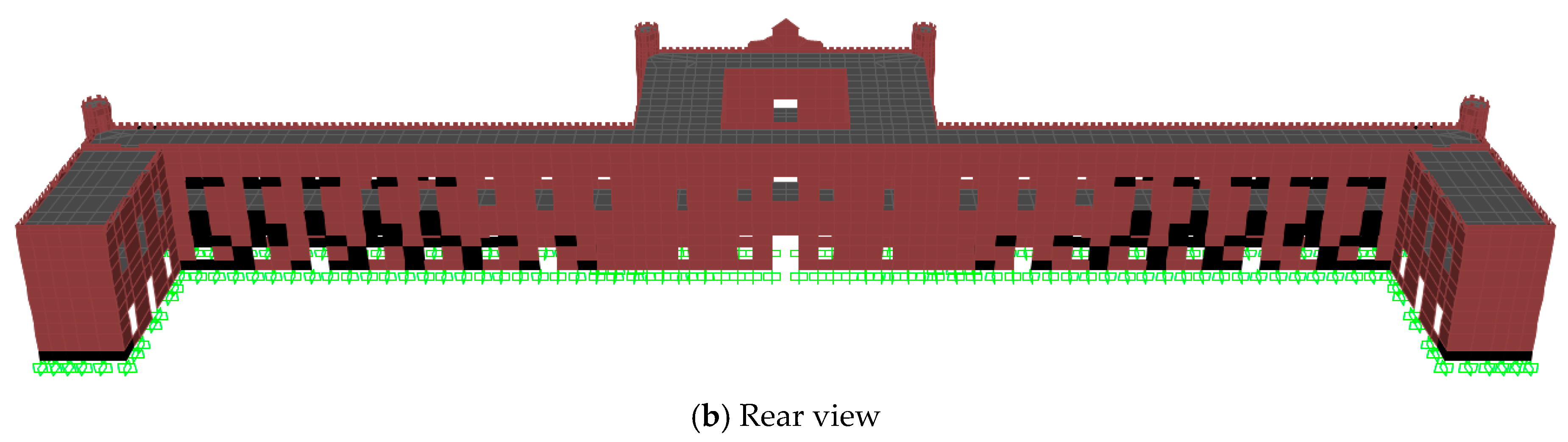
When analyzing the results of the elastic model, it was observed that a large portion of the walls present high tensile stresses values which is interpreted as damaged area; however, because the analysis is linear, a redistribution of stresses cannot be generated, so they will increase proportionally without limit. As a result, in order to generate a stress redistribution, it was decided to perform an analysis in which the elements’ elasticity modules whose major principal stresses exceed the diagonal tensile resistance are reduced, so that these zones reduce their tensile stresses. This idea has already been implemented in the geometric correction analysis of the Metropolitan Cathedral [19]. Details on the implementation of linear sequential analysis can be found in [20,21]. Figure 17 shows the elements with reduced elastic modulus.
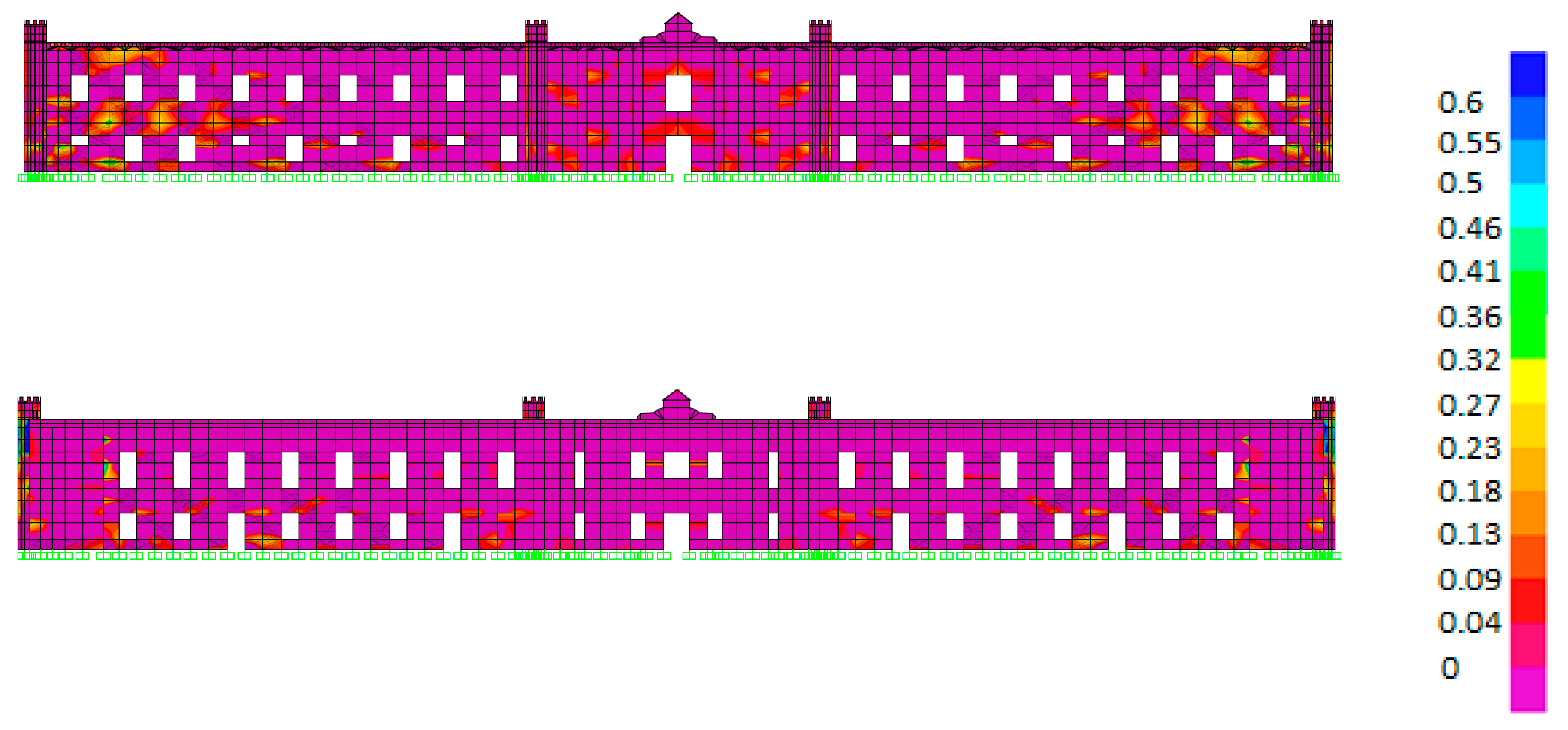
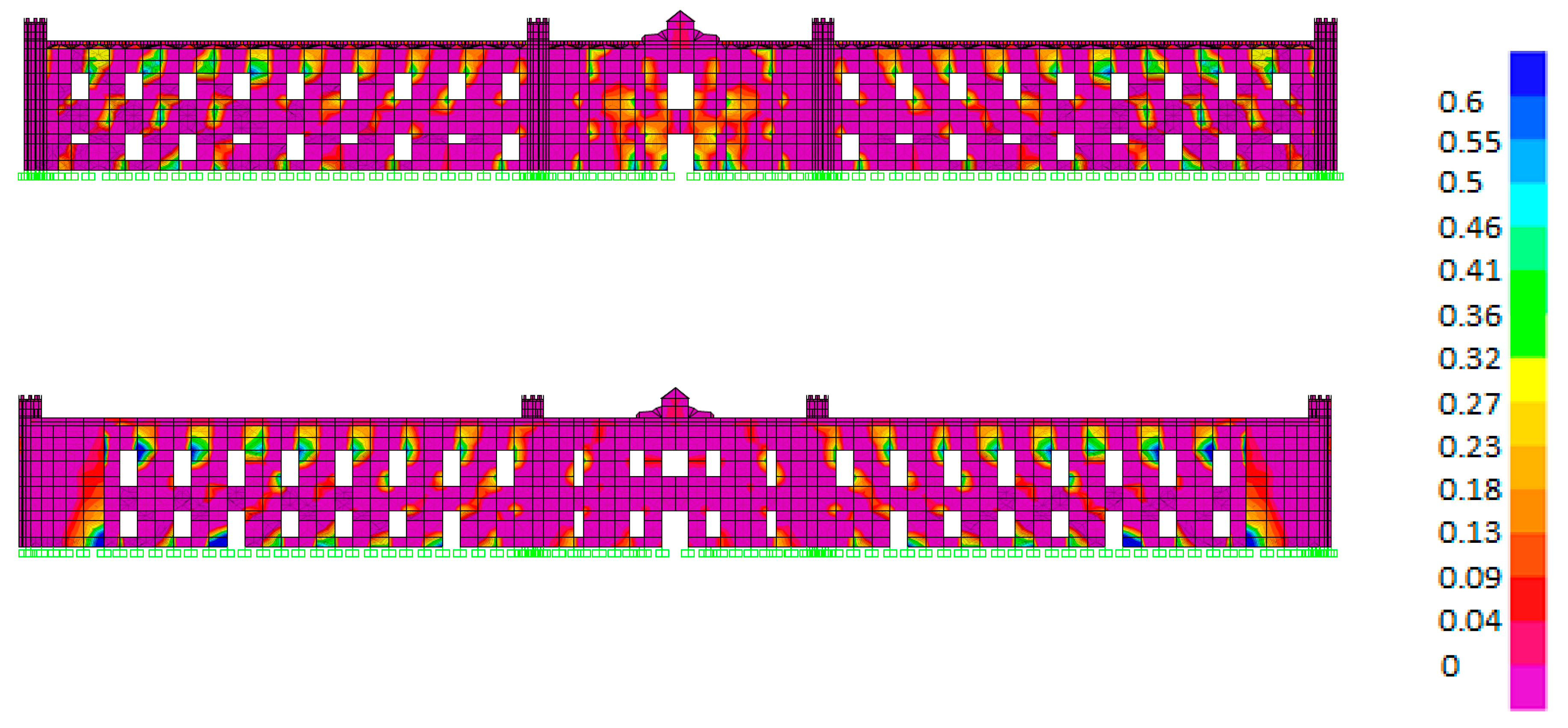
Figure 18 shows the maps of horizontal axial stresses that resulted from this analysis. These maps display tensile stress concentrations between 0.2 and 0.4 MPa at both ends of the model, at the front mainly; this contrasts with Figure 15 and Figure 16 in which the stresses in the same areas are over 0.4 MPa.
The vertical axial stresses shown in Figure 19 indicate that zones with tensile concentrations are the openings of the model, in contrast to Figure 15 and Figure 16 in which tensions on the windows are higher than 0.6 MPa; stresses on the majority of the windows were reduced to 0.4 MPa in the linear sequential model.
Lastly, the main principal stresses on the maps in Figure 20 show that the tensile stress concentrations are located in the door and window corners, as well as in the zones where there are supports. This differs from the elastic model, in which a large part of the walls present tensile stresses. In contrast to Figure 15 and Figure 16, it is observed that wall stresses located between windows reduce their tensile stresses.
5. Conclusions
In general terms, the safety of the Government Building is acceptable as a result of the constant maintenance it has received in recent years and the remodeling works to which it has been subjected.
The ambient vibration test performed shows that the building has a complex dynamic behavior. This is mainly due to the fact that the slabs cannot be considered as stiff diaphragms. Thus, the numerical model needs more than 400 modes to reach 90% of the effective weight to perform a spectral modal analysis. The need for more than 400 modes means that there are several local modes. These local modes involve the out of plane vibration of the walls, wings and slabs.
The seismic behavior study shows that according to the Mexican Building Code, the building is able to withstand seismic actions. Consequently, its situation is not critical as a result of its high stiffness, the density of its walls, and the fact that its period is far from the soil’s period.
The building’s critical condition comes from the differential settlements it presents. They are the cause for the damages present in the construction. Currently, these damages do not jeopardize the building’s stability; however, if they continue to increase a critical situation could be reached.
The non-linear finite element model used to study the overall response of the building due to differential settlements is based on the assumption of smeared crack damage. The main stress maps derived from the differential settlements study revealed that the main vulnerable zones (doors and windows, particularly those located in the Government Building) are a result of tensile stresses. This can also be attributed to its vast length according to its geometric configuration.
It should be noted that the profile of differential settlements is an approximation of the real one, since the topographical information of the real profile was not available. A parabolic profile was used and it gives a good approximation with the real one. This can be observed by comparing the damage obtained with the finite element model and the real damage to the building. This damage is concentrated in the ends of the wing of the building, mainly in the area of the ground floor where the tensile stresses appear due to the flexion that the building suffers.
Author Contributions
M.M.C. is responsible for the research project. F.P. supervised and reviewed the numerical model results. C.C. carried out the seismic behavior study. G.M. undertook the differential settlements analysis.
Funding
This research received no external funding.
Acknowledgments
The Seismology Coordination of the Engineering Institute of UNAM is acknowledged for its valuable contribution with the Government Building’s ambient vibration tests.
Conflicts of Interest
The authors declare no conflict of interest. The funders had no role in the design of the study; in the collection, analyses, or interpretation of data; in the writing of the manuscript, and in the decision to publish the results.
References
- El Archivo General de la Nación Escribe una Nueva Página en la Historia de la Archivística Nacional. Available online: http://www.gobernacion.gob.mx/work/models/SEGOB/Resource/1325/1/images/Proyecto_de_Construccion_del_Nuevo_Edificio_del_Archivo_General_de_la_Nacion_y_Remodelacion_de_las_instalaciones_actuales.pdf (accessed on 8 May 2016).
- Wilson, E.; Habibullah, A. Series of Computer Programs for Finite Element Analysis of Structures; User Manual, SAP NL 2000; Computers & Structures, Inc.: Berkeley, CA, USA, 1989. [Google Scholar]
- Gobierno del Distrito Federal (GDF). Reglamento de Construcciones para el Distrito Federal (RCDF); Gobierno del Distrito Federal: Mexico City, Mexico, 2004. [Google Scholar]
- Betti, M.; Bartoli, G. Evaluation study on structural fault of a Renaissance Italian palace. Eng. Struct. 2010, 32, 1801–1813. [Google Scholar] [CrossRef]
- Alessandri, C.; Garutti, M.; Mallardo, V.; Milani, G. Crack patterns induced by foundation settlements: Integrated analysis on a Renaissance masonry palace in Italy. Int. J. Arch. Herit. 2015, 9, 111–129. [Google Scholar] [CrossRef]
- Meli, R.; Sánchez-Ramírez, R. Criteria and experiences on structural rehabilitation of stone masonry buildings in Mexico City. Int. J. Arch. Herit. 2007, 1, 2–28. [Google Scholar] [CrossRef]
- Betti, M.; Vignoli, A. Assessment of seismic resistance of a basilica-type church under earthquake loading: Modelling and analysis. Adv. Eng. Softw. 2008, 39, 258–283. [Google Scholar] [CrossRef]
- Nava, A.E. La Independencia de México. A 200 Años de su Inicio. Pensamiento Social y Jurídico; Facultad de Derecho de la UNAM: México City, Mexico, 2010; pp. 361–362. ISBN 978-607-02-1550-6. [Google Scholar]
- García, E. Lorenzo de la Hidalga. In Del Arte. Homenaje a Justino Fernández; Instituto de Investigaciones Estéticas, Universidad Nacional Autónoma de México: Mexico City, Mexico, 1977; p. 16. [Google Scholar]
- El “Palacio Negro” de Lecumberri. Available online: http://www.eluniversal.com.mx/articulo/metropoli/cdmx/2016/05/1/el-palacio-negro-de-lecumberri (accessed on 6 May 2016).
- El Palacio de Lecumberri. Remodelación de Lecumberri. Available online: http://www.agn.gob.mx/guiageneral/imag_lecumberri3.htm (accessed on 5 May 2016).
- Instituto de Ingeniería de la UNAM. Estudios Técnicos en las Materias de Ingeniería Geotecnia Y Estructural relativos a la Construcción del Nuevo Edificio del Archivo General de la Nación Y Remodelación de las Instalaciones Actuales. Informe Final: Aspectos Estructurales; Instituto de Ingeniería de la UNAM: Mexico City, Mexico, 2016. [Google Scholar]
- Meli, R. Ingeniería Estructural de los Edificios Históricos; Fundación ICA: Mexico City, Mexico, 1998. [Google Scholar]
- Gobierno del Distrito Federal (GDF). Normas Técnicas Complementarias Sobre Criterios y Acciones para el Diseño Estructural de las Edificaciones (NTC-Criterios); Gobierno del Distrito Federal: Mexico City, Mexico, 2004. [Google Scholar]
- Gobierno del Distrito Federal (GDF). Normas Técnicas Complementarias para Diseño y Construcción por Sismo (NTC-S); Gobierno del Distrito Federal: Mexico City, Mexico, 2004. [Google Scholar]
- Instituto de Ingeniería, UNAM. Mediciones de los Periodos de Traslación y Torsión del Edificio que Resguarda el Archivo General de la Nación. Informe; Ingeniería Sismológica: Mexico City, Mexico, 2016. [Google Scholar]
- Monroy, G. Estudio de una Técnica de Refuerzo para el Edificio de Gobierno del Archivo General de la Nación; Tesis de licenciatura, UNAM: Mexico, Mexico City, 2018. [Google Scholar]
- Meli, R.; Peña, F. On elastic models for evaluation of the seismic vulnerability of masonry churches. In Structural Analysis of Historical Construction; Modena, C., Lourenço, P., Roca, P., Eds.; CRC Press/Balkema Press: Rotterdam, The Netherlands, 2004; Volume II, pp. 1121–1132. [Google Scholar]
- García, A.N. Análisis Estructural de una Propuesta de Corrección Geométrica para la Catedral Metropolitana; Tesis de Licenciatura, UNAM: Mexico City, Mexico, 1995. [Google Scholar]
- Rots, J. Sequentially linear continuum model for concrete fracture. In Fracture Mechanics of Concrete Structures; de Borst, R., Mazars, J., Pijaudier-Cabot, G., van Mier, J.G.M., Eds.; CRC Press/Balkema Press: Rotterdam, The Netherlands, 2001; pp. 831–839. [Google Scholar]
- Rots, J.; Invernizzi, S. Regularized sequentially linear saw-tooth softening model. Int. J. Numer. Anal. Methods Geomech. 2004, 28, 821–856. [Google Scholar] [CrossRef]
Figure 1.
Antonio Torres Torija, overall distribution plane of the prison ground floor [9].
Figure 1.
Antonio Torres Torija, overall distribution plane of the prison ground floor [9].

Figure 2.
Aerial view of the old Lecumberri Prison (1970s) [10].
Figure 2.
Aerial view of the old Lecumberri Prison (1970s) [10].

Figure 3.
Frontal view of the building circa 1980 [11].
Figure 3.
Frontal view of the building circa 1980 [11].

Figure 4.
Plan view of the Government Building of the General Archive of the Nation (AGN) (dimensions in m) [12].
Figure 4.
Plan view of the Government Building of the General Archive of the Nation (AGN) (dimensions in m) [12].

Figure 5.
Layout of the damage survey on axis C [9].
Figure 5.
Layout of the damage survey on axis C [9].

Figure 6.
Layout of the damage survey on axis B [9].
Figure 6.
Layout of the damage survey on axis B [9].


Figure 7.
AGN Government Building floor-use [12].
Figure 7.
AGN Government Building floor-use [12].


Figure 8.
Finite elements model (tridimensional lateral view) [12].
Figure 8.
Finite elements model (tridimensional lateral view) [12].

Figure 9.
Displacements by own weight and maximum live load in vertical direction (cm) [12].
Figure 9.
Displacements by own weight and maximum live load in vertical direction (cm) [12].

Figure 10.
Design spectra for structures type A, according to [15].
Figure 10.
Design spectra for structures type A, according to [15].

Figure 11.
Seismic displacement and distortion measuring points by level.

Figure 12.
Seismic combination 100%Sx + 30%Sy: (a) direction x, (b) direction y; seismic combination 30%Sx + 100%Sy: (c) direction x, (d) direction y.
Figure 12.
Seismic combination 100%Sx + 30%Sy: (a) direction x, (b) direction y; seismic combination 30%Sx + 100%Sy: (c) direction x, (d) direction y.


Figure 13.
Map of vertical and horizontal axial stresses (MPa): (a) earthquake combination 100%Sx + 30%Sy; (b) earthquake combination 30%Sx + 100%Sy.
Figure 13.
Map of vertical and horizontal axial stresses (MPa): (a) earthquake combination 100%Sx + 30%Sy; (b) earthquake combination 30%Sx + 100%Sy.

Figure 14.
Model deformation resulting from a combination of loads plus the pattern of parabolic settlements (displacements scale factor 1:20).
Figure 14.
Model deformation resulting from a combination of loads plus the pattern of parabolic settlements (displacements scale factor 1:20).

Figure 15.
Comparison between stresses (MPa) at the front and existing damage.

Figure 16.
Comparison between rear stresses (MPa) and existing damage.

Figure 17.
Elements with reduced elastic modulus.


Figure 18.
Map of the horizontal axial stresses (MPa) from the linear sequential model, front and rear views.
Figure 18.
Map of the horizontal axial stresses (MPa) from the linear sequential model, front and rear views.

Figure 19.
Map of the vertical axial stresses (MPa) from the linear sequential model, front and rear views.
Figure 19.
Map of the vertical axial stresses (MPa) from the linear sequential model, front and rear views.

Figure 20.
Map of the major principal stresses (MPa) from the linear sequential model, front and rear views.
Figure 20.
Map of the major principal stresses (MPa) from the linear sequential model, front and rear views.


Table 1.
Mechanic properties used for the numerical model.
| Material | Volumetric Weight (kN/m3) | Elasticity Modulus (MPa) |
|---|---|---|
| Brick with lime mortar (walls) | 15.70 | 981 |
| Concrete (slabs) | 23.54 | 21,712 |
Table 2.
Finishings and installations loads.
| Element | Load (N/m2) |
|---|---|
| Dividing dry walls | 1200 |
| Floors and finishings | 1200 |
| Electric and hydro-sanitary installations | 200 |
| Soffit | 200 |
Table 3.
Live loads by floor.
| Live Loads * | ||||
|---|---|---|---|---|
| Floor | Use | Wmax (N/m2) | Wa (N/m2) | Wm (N/m2) |
| GROUND FLOOR | Offices | 2500 | 1800 | 1000 |
| Exhibition and meeting area | 3500 | 2500 | 400 | |
| Vestibule and free access passage | 3500 | 1500 | 400 | |
| LEVEL 1 | Offices | 2500 | 1800 | 1000 |
| Exhibition and meeting area | 3500 | 2500 | 400 | |
| Vestibule and free access passage | 3500 | 1500 | 400 | |
| Archive | 3500 | 2500 | 400 | |
| ROOFTOP | Rooftop with slope < 5% | 1000 | 700 | 150 |
* Wmax: maximum live load; Wa: instant live load; Wm: average live load.
Table 4.
Weights obtained from the numerical model.
| Weight | Numeric Model (kN) |
|---|---|
| Own weight (PP) | 108,092.43 |
| PP + Wmax | 120,332.01 |
| PP + Wa | 116,083.67 |
| PP + Wm | 110,955.67 |
Table 5.
Review of permissible displacements by own weight and maximum load.
| Zone | Own Weight | Review | ||
|---|---|---|---|---|
| Δelastic (cm) | Δslab (cm) | Δmáx (cm) | Δmáx > Δlosa | |
| 1 | 1.40 | 2.80 | 4.08 | Ok |
| 2 | 1.40 | 2.80 | 4.08 | Ok |
| 3 | 2.05 | 4.10 | 4.46 | Ok |
| 4 | 2.05 | 4.10 | 4.46 | Ok |
Table 6.
Characteristics of the first 4 vibration modes.
| Mode 1; T = 0.590 s | Mode 2; T = 0.587 s | Mode 3; T = 0.381 | Mode 4; T = 0.340 s |
|---|---|---|---|
 |  |  |  |
| First transversal mode | Second transversal mode. The movement is in a transversal direction but counter-phase to the building’s wings | Third transversal mode. The movement is in transversal direction. The central part of the building moves counter-phase to the wings | First torsional mode |
Table 7.
Numerical model and ambient vibration tests (AVT) periods and modal shapes.
| AVT = 0.80–0.60 s Mode 1; T = 0.590 s | AVT = 0.42–0.40 s Mode 3; T = 0.381 s | AVT = 0.30 s Mode 4; T = 0.340 s | ||||||
|---|---|---|---|---|---|---|---|---|
| AVT predominant movement | Transversal |  | AVT predominant movement | Transversal |  | AVT predominant movement | Torsion |  |
| Modal form: first transversal mode | Modal form: third transversal mode wing and central part counter-phase | Modal form: first torsional mode | ||||||
Table 8.
Base shear forces.
| Combination | Basal Shear (kN) | |
|---|---|---|
| Longitudinal x | Transversal y | |
| 100%Sx + 30%Sy | 15,285 | 9072 |
| 30%Sx + 100%Sy | 4616 | 30,138 |
© 2018 by the authors. Licensee MDPI, Basel, Switzerland. This article is an open access article distributed under the terms and conditions of the Creative Commons Attribution (CC BY) license (http://creativecommons.org/licenses/by/4.0/).
Share and Cite
MDPI and ACS Style
Chávez, M.M.; Peña, F.; Cruz, C.; Monroy, G. Structural Behavior of the General Archive of the Nation (AGN) Building, Mexico. Infrastructures 2018, 3, 39. https://0-doi-org.brum.beds.ac.uk/10.3390/infrastructures3030039
AMA Style
Chávez MM, Peña F, Cruz C, Monroy G. Structural Behavior of the General Archive of the Nation (AGN) Building, Mexico. Infrastructures. 2018; 3(3):39. https://0-doi-org.brum.beds.ac.uk/10.3390/infrastructures3030039
Chicago/Turabian StyleChávez, Marcos M., Fernando Peña, Claudia Cruz, and Gustavo Monroy. 2018. "Structural Behavior of the General Archive of the Nation (AGN) Building, Mexico" Infrastructures 3, no. 3: 39. https://0-doi-org.brum.beds.ac.uk/10.3390/infrastructures3030039