Article

Chloride Penetration at Cold Joints of Structural Members with Dissimilar Concrete Incorporating UHPC

Civil and Environmental Department, Florida International University, Miami, FL 33174, USA
*
Author to whom correspondence should be addressed.
Submission received: 3 April 2019 / Revised: 22 April 2019 / Accepted: 22 April 2019 / Published: 24 April 2019

Abstract

:
Ultra-high-performance concrete (UHPC) has been introduced for reinforced concrete structures due to its enhanced mechanical performance, including high compressive strength and tensile capacity. In certain applications, such as closure joints, connections, and concrete repairs, reinforcing steel may be embedded in dissimilar concrete elements partially incorporating UHPC. Superficially, UHPC can be considered to provide enhanced corrosion durability in marine environments due to its low permeability which would mitigate chloride-induced corrosion of rebar in the bulk material. However, the chloride intrusion through cold joints can be faster than that in bulk concrete and may jeopardize the durability of structures. This research examines the possibility of enhanced chloride transport at the cold joint incorporating UHPC. The effectiveness of the bond on chloride penetration at the concrete interface with various levels of moisture availability for the substrate at the time of UHPC repair was examined. To this effect, the substrate concrete was conditioned to different moisture content including 0%, 75%, and 100% relative humidity, and soaked prior to UHPC repair concrete casting. Chloride penetration was accelerated by an impressed current source and assessed by silver nitrate solution sprayed on the cold joint. Moreover, the tensile bond strength between substrate concrete and UHPC was measured using the splitting tensile test.

1. Introduction

Ultra-High-Performance Fiber Reinforced Concrete (UHPFRC), usually known as UHPC, is a cementitious material formulated with an optimized gradation of granular constituents, a water-to-cementitious-materials ratio of 0.2, and a high percentage of internal fiber reinforcement. The resulting product is concrete with improved strength, ductility, and workability relative to normal or even high-performance concrete [1,2,3]. Moreover, the ultra-high dense material of UHPC mixes results in low permeability which provides high resistance to the ingress of oxygen and chlorides [4,5,6]. UHPC as a strengthening compound in structural design has received considerable attention [7,8,9,10,11], particularly for repair applications. Its low permeability characteristics would ideally promote long-term durability, improve the service life of structures by limiting the ingression of harmful agents, and thereby improve the sustainability by reducing the repair as well as reconstruction requirements. In repair applications, UHPC would be cast alongside the hardened Normal Strength Concrete (NSC) substrate. Applications may include the use of UHPC as an overlay, joints for precast elements [12,13], or local patch repairs. Therefore, the adhesion at the cold joint interface is of crucial importance in the utilization of this material for a repair application. Mechanical adhesion in such composite members largely relies on the hardening of the added mixture as well as adequate substrate roughness, cleanliness, and moisture availability [14]. However, the long-term corrosion durability of these repair applications with the different exposure condition of NSC substrate concrete still requires attention. The effect of corrosion macrocells that may develop between the UHPC repair and NSC substrate has been explored in earlier work by the authors [4]. In that work, vestigial chloride concentrations in the substrate concrete and chloride penetration by bulk diffusion was considered. However, preferential chloride ingress and carbonation through concrete cold joints [15,16,17,18] may occur. In the following, the role of the dissimilar concrete interface on chloride penetration was considered. Preferential ingress of harmful ions such as chlorides, particularly in marine environments, can jeopardize the durability of such structures. The objective of the work here was to identify if the cold joint between the UHPC repair and the NSC substrate concrete may allow preferential chloride penetration. The effectiveness of the bond at the concrete interface (with various levels of moisture availability at the time of UHPC repair) to minimize chloride penetration was examined. To this effect, the substrate concrete was conditioned to various moisture contents (5%, 75%, 100% RH (relative humidity), and wet) prior to and after UHPC repair concrete casting. It should be noted that RH (relative humidity) is the amount of water vapor present in air expressed as a percentage of the amount needed for saturation at the same temperature.

2. Experimental Study

2.1. Material Properties

The experiments included casting of two concrete types: Normal Strength Concrete (NSC), and Ultra High-Performance Concrete (UHPC). The concrete mix proportions are listed in Table 1. The NSC comprised of Type II Portland cement, crushed limestone coarse aggregate (maximum size 9.5 mm), and sand fine aggregate. The UHPC used in this study was an available commercial product, composed of a blended premix powder, water, superplasticizer, and 2% steel fibers by volume. The premix powder included cement, silica fume, ground quartz, and sand. The fibers were 13 mm long, with a tensile strength of 2800 MPa.
The NSC mix had a water-to-cement (w/c) ratio of 0.39 with a slump of 180 mm. A flow table test was performed according to ASTM C143 [19] to obtain the rheology of the UHPC mix. Static and dynamic flowability of UHPC was measured as 200 mm and 250 mm, respectively. The compressive strength test was carried out on cylinder specimens of 75 mm diameter and 150 mm length using ASTM C 39 guidelines [20]. Three cylinders were tested to determine the 28-days compressive strength. Furthermore, the tensile properties of UHPC and NSC were obtained through the flexural toughness test procedure following ASTM C1018 [21]. The values of the material properties are presented in Table 2.

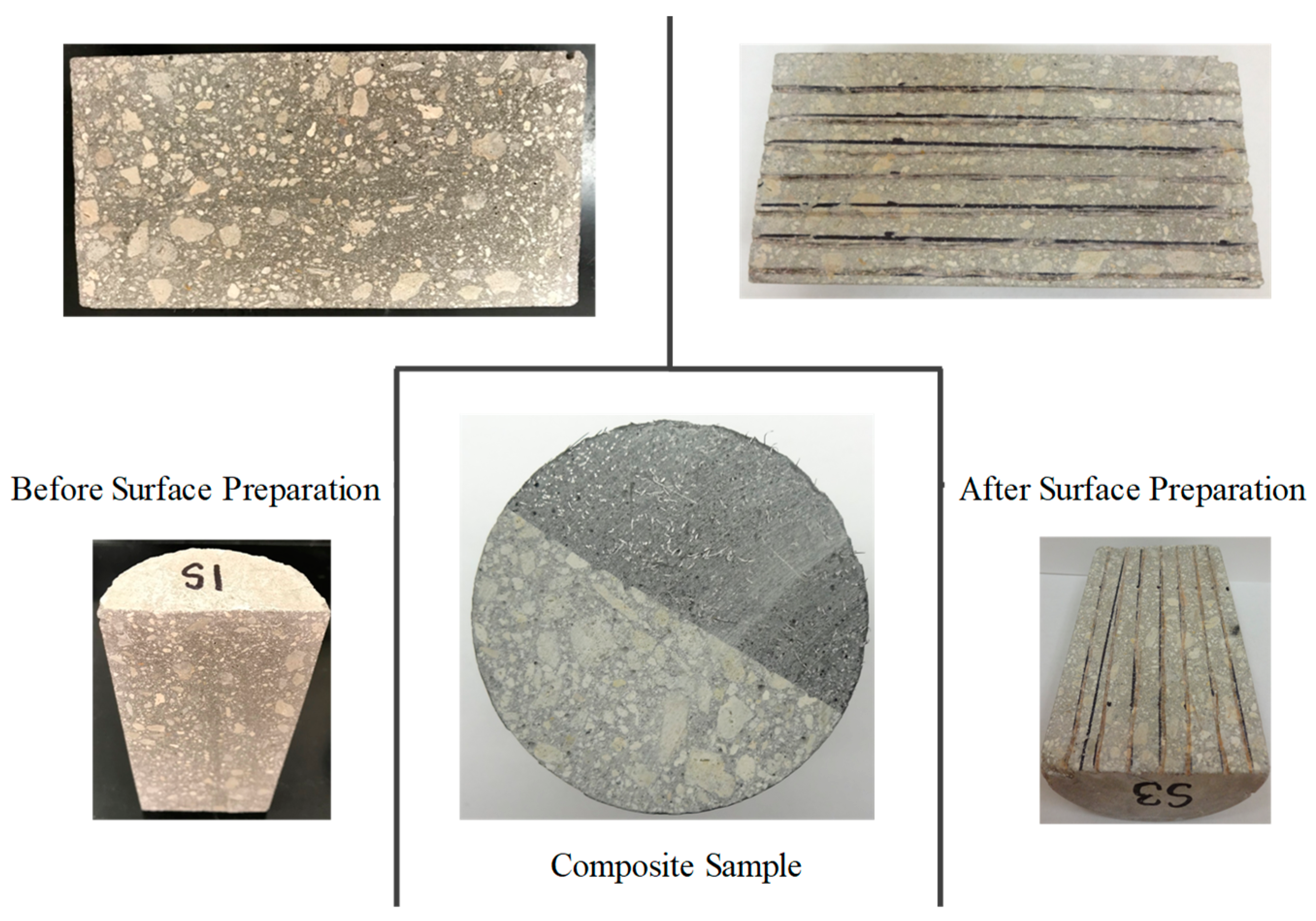
2.2. Preparation of Samples

In this work, an experimental investigation was designed to evaluate the effect of the substrate moisture content and its relationship with the bonding performance of ultra-high-performance concrete (UHPC) with existing concrete (NSC). Twelve test specimens were cast in 75 × 150 mm plastic molds. Eight of those samples were composite samples made by the partial casting of NSC and UHPC creating a lift of the dissimilar concretes in the geometry of two half cylinders. The base NSC portions were made by cutting an initial full concrete cylinder divided into two half cylinders. After 60 days of conditioning (in either 0%, 75%, 100% RH, or soaked), the smooth cut surfaces were roughened by cutting parallel grooves (3 mm deep with 100 mm spacing) whereupon the specimens were reset in a cylinder mold (75 × 150 mm) and the remaining void spaces were cast with UHPC, as shown in Figure 1. The remaining four specimens consisted of full NSC or UHPC that was soaked in water. The specimens were demolded after seven days of curing within the plastic mold and placed in the various conditioning environments for 190 days.

2.3. Methodology

A modified version of the Rapid Chloride Penetration Test (RCPT) [22] was used to measure the chloride penetration through the cold joint. This test included the electrical conductance determination of concrete to deliver a rapid indication of its resistance to the penetration of chloride ions. The external electrical potential was applied axially across the specimens and allowed for the possible migration of chloride ions into the specimens. After the test duration (21 days), the specimens were axially split, and a silver nitrate solution was sprayed on to one side of the freshly split sections. Then the chloride penetration depths were measured from the visible white silver chloride precipitation.
The diffusion test cells were set up with a cylindrical specimen with 75 mm diameter and 150 mm in length, as shown in Figure 2. The flat portions of the specimens were uniformly ground to create smooth surfaces. Acrylic tubes used as a ponding dam were attached to the top surfaces. The ponds were filled with a 10% NaCl solution. Epoxy sealer was used around the base of the ponding dams and extended on the outer surfaces of the cylinders to minimize salt solution leakage and weeping on the surfaces of the specimens. The bottom portions of the specimens were set into a shallow solution of lime water. Titanium mesh electrodes were placed at both ends and 25 Volts was applied by a DC power supply for 21 days to allow the electrical migration of chloride ions to flow through the samples. The current passing through the cold joints of the composite samples in a non-steady state condition was measured to assess the resistance of the concrete specimens to chloride ion penetration. Then charge passed was calculated by integrating the current-time curve for the test exposure period.
After 21 days of exposure, the samples were disconnected and prepared for the splitting test to measure the bond strength. The tensile strength of the splitting cylinder was calculated using Equation (1) given by:
T = 2 P π Ar
where, T is the tensile strength of the splitting cylinder; P is the maximum applied load, and AT is the area of the bond plane.
After the splitting test, the depths of the chloride penetration were examined on one half of the specimens (on the substrate plane part) using a colorimetric technique in which silver nitrate solution (1M) was used as an indicator.

3. Result and Discussion
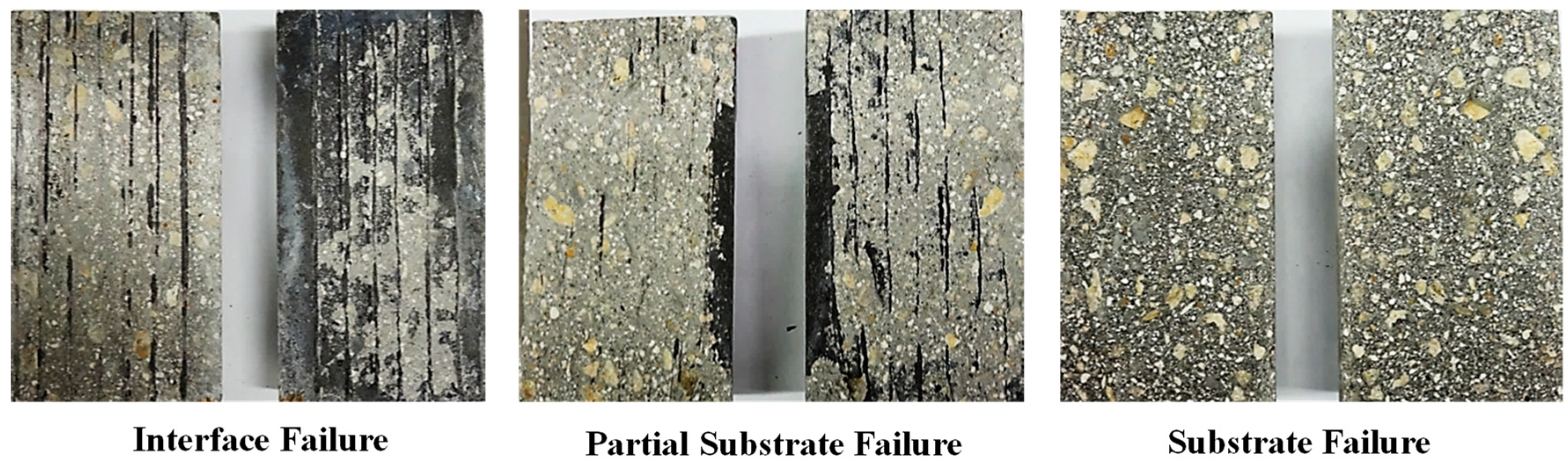
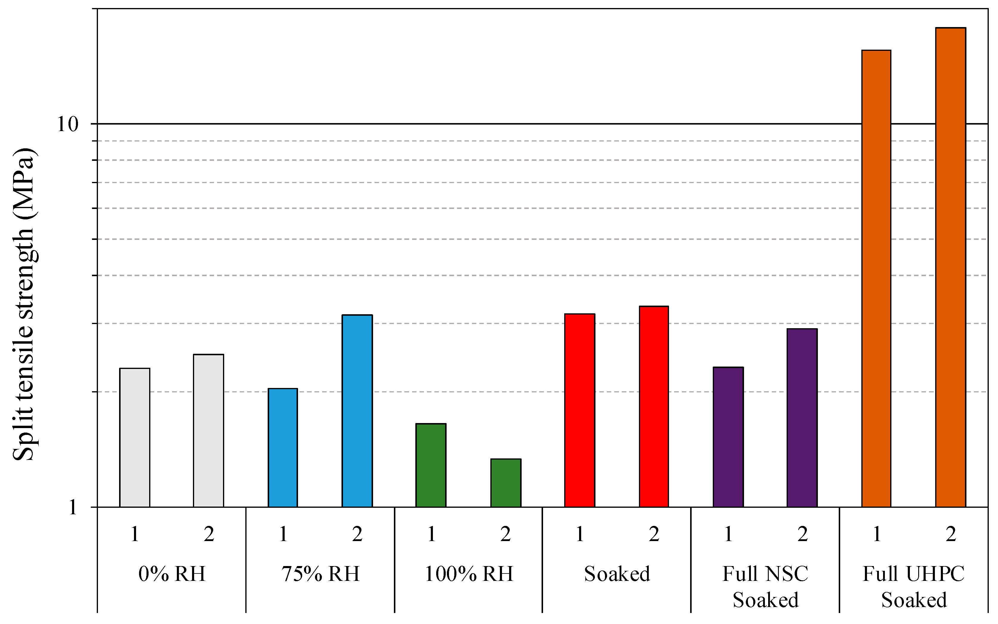
3.1. Bond Strength

Three different failure modes of the splitting cylinder tensile test were observed during the test, as shown in Figure 3. These three failure types are represented as Type A = pure interface failure, Type B = interface failure with partial substrate failure, and Type C = substrate failure. The results showed that the bonding for the surface roughened composite specimens were generally strong since most of the composite specimens failed in the NSC substrate.
Failure of composite samples exposed to 0% relative humidity occurred at the interface. This can be attributed to the fact that when new concrete (UHPC) was applied to a dry substrate concrete surface, part of its mixing water was absorbed into the substrate concrete and the cementitious materials in the UHPC directly in contact did not adhere firmly to the substrate concrete [23].
The tensile strength of the splitting cylinder was calculated using Equation (1), and the values are shown in Figure 4. The results showed the enhanced tensile performance of bulk UHPC, 5 times greater than bulk NSC, which is apparently due to the ‘‘bridging effect” of steel fiber in UHPC.
The general splitting tensile strength of the composite samples indicated an adequate strength level of bonding (>1.4 MPa), based on the quantitative bond strength quality proposed by Sprinkel and Ozyildirim [24]. Generally, improved bonding performance between UHPC and substrate NSC regardless of the moisture content of the substrate can be attributed to the good workability of UHPC which enhanced its capability to fill the pores on the substrate surface [14,25]. The good bond strength for the composite samples ensured that the ionic flow in the electrical migration test described next was related to the transport through the bulk material and cold-joint interface. No bond degradation or mechanical flaw was measured in the composite samples that would otherwise affect chloride transport.
The relatively small-sized samples did not capture well the influence of moisture on the bond strength, but some distinct behavior was observed between the samples with differential environmental moisture exposure conditions.

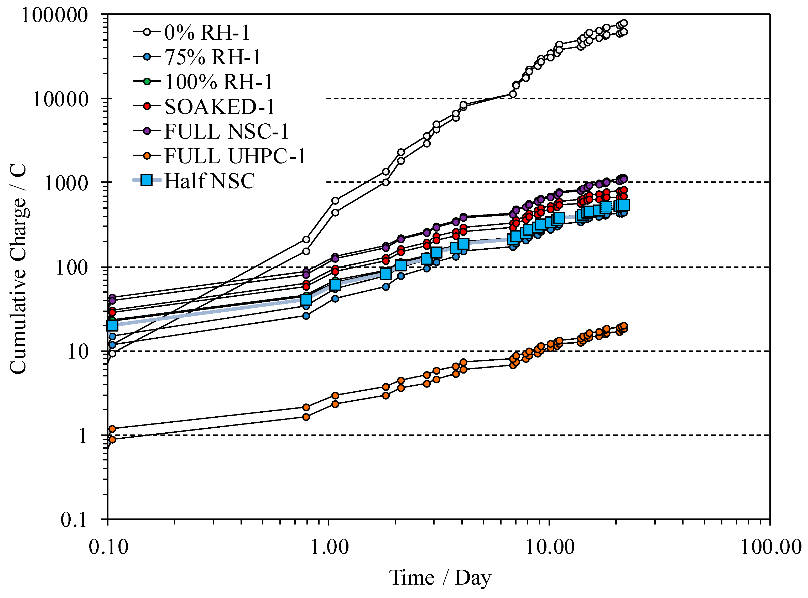
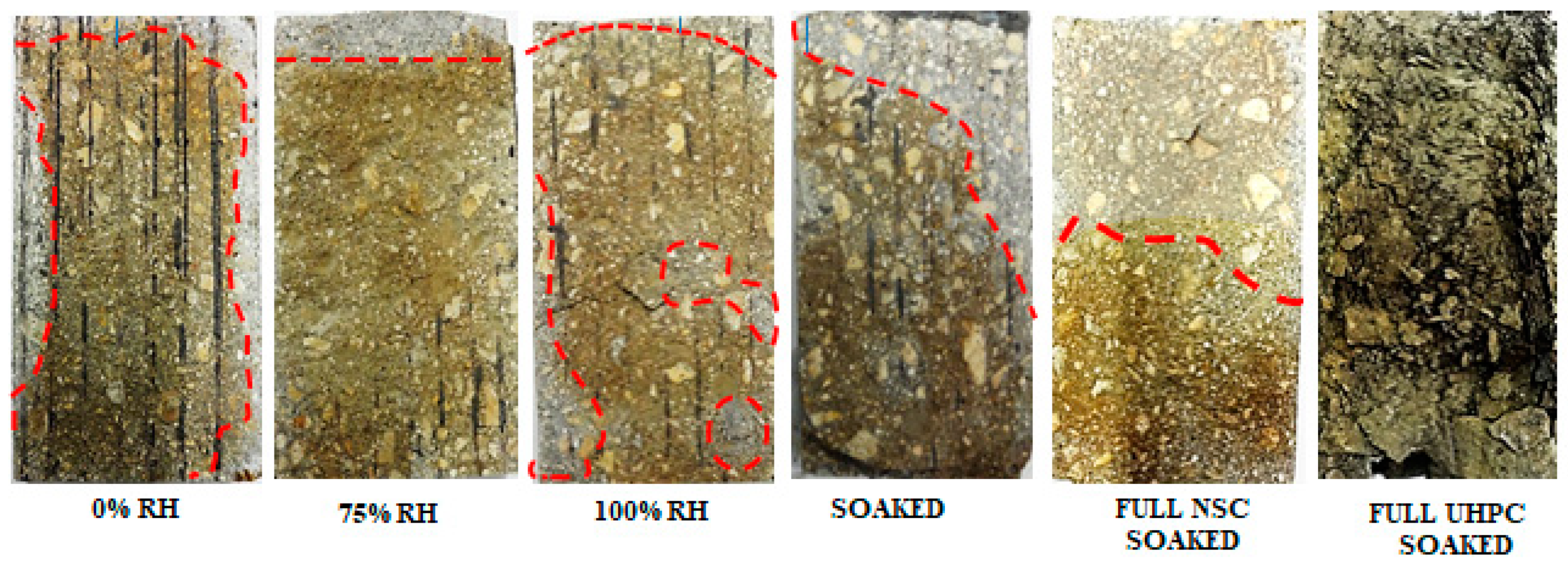
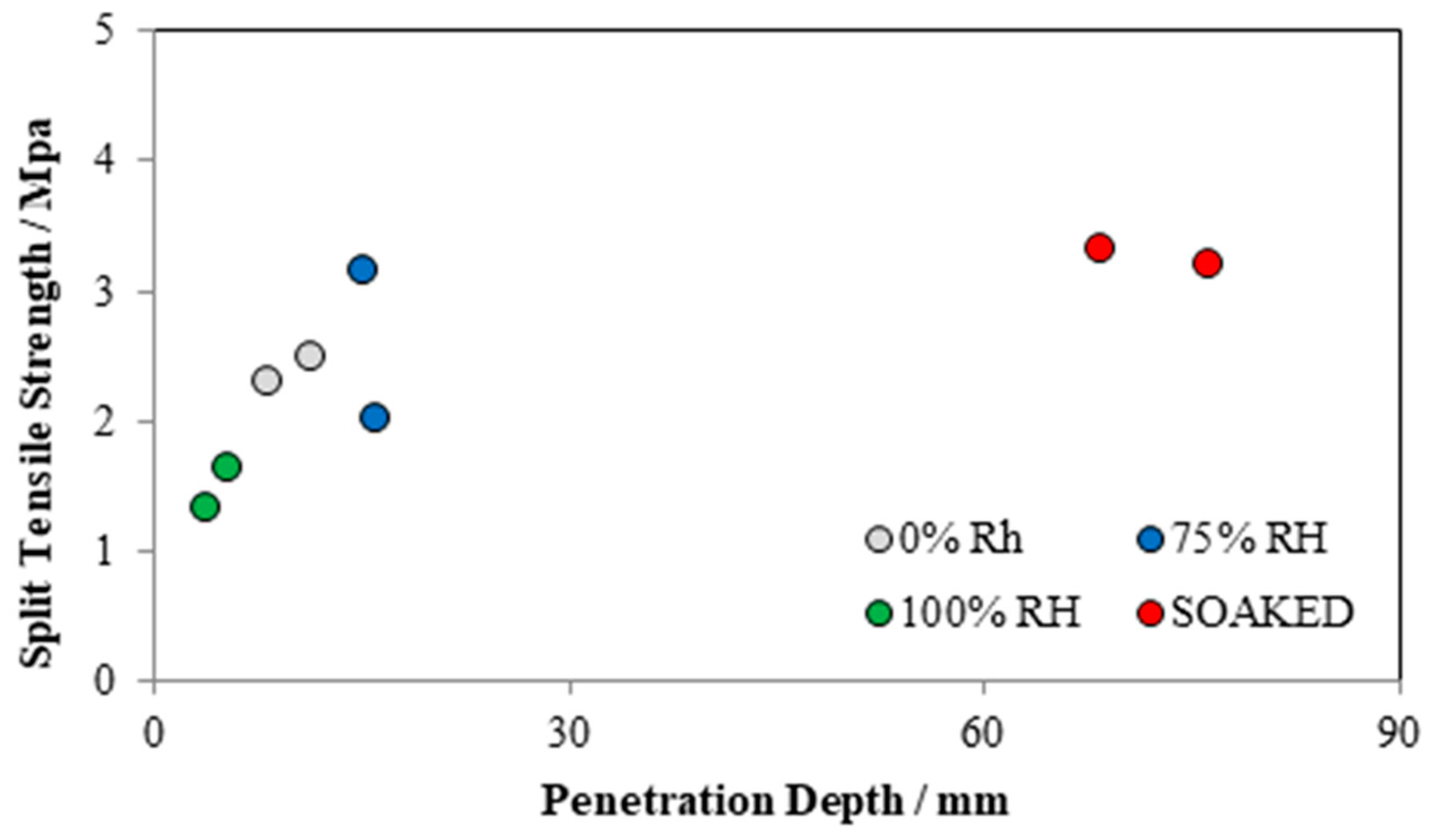
3.2. Chloride Penetration

Figure 5 shows the RCPT results in term of Total Charge Passed (TCP) in coulombs for the NSC substrate, UHPC, and the composite of NSC/UHPC with different substrate surface moisture content. The TCP could be related to the resistance of the concrete samples against chloride ion penetration. A lower TCP value indicated greater resistance to chloride ion penetration.
As shown in Figure 5, the plain UHPC specimens had the lowest TCP values (i.e., 21 coulombs at 21 days), while the plain NSC specimen had TCP values more than 1100 coulombs after 21 days. As expected, the low bulk permeability of UHPC resulted in significantly lower chloride ion migration.
All the composite specimens, except the samples where substrate NSC had 0% RH before UHPC placement, exhibited TCP values of less than 750 coulombs after 21 days. This also seemed to signify that the conditioning environments for the NSC substrate (75%, 100% RH, and soaked) did not have a major influence on chloride permeability during the testing period. Adequate surface preparation with sufficient moisture levels apparently provided good bonding for all composite samples and similar performance to resist chloride ion penetration.
The high value of the recorded TCP for of the composite samples where the substrate had 0% RH before UHPC placement (70,000 coulombs) can be contributed to the capillary absorption of the NSC substrate, leading to quick absorption of chloride solution. Capillary absorption is very rapid and strong transport mechanisms compared to the other transport mechanisms.
Assuming that the flux of chloride transport is proportional to the surface area of the NSC (and little current passes through the UHPC component), the total ionic current passing through the composite concrete specimens would ideally result in a 1:2 ratio compared to the plain NSC samples. However, in the composite samples with 100% RH, the TCP values were larger. This could be an indication of preferential chloride penetration through the joint.
To assess the chloride penetration path through the joint interface, after splitting the samples under load, the substrate surfaces were sprayed with 1M AgNO3 solutions. The specimens were allowed to dry naturally at room temperature for 30 min. When a silver nitrate solution is sprayed on a concrete surface containing chloride ion, a photochemical reaction occurred. The chlorides bind with the silver to produce silver chloride (white precipitate). In the absence of chlorides, the silver instead bonds with the hydroxides present in the concrete and forms a brown precipitate of silver oxide [26]. Representative photos after spraying AgNO3 indicator are shown in Figure 6. NT Build 492 [22] recommends utilizing a suitable ruler to measure the penetration depths after the chloride migration test. Based on that, seven depths were measured, and an average measurement is shown in Table 3.
Chloride penetration could be readily observed by the differentiation in surface coloration on the NSC portion of the specimens, and bulk chloride penetration was generally seen in the upper portion of the specimens. No chloride penetration could be captured for UHPC samples mainly due to its remarkable impermeability. A generally uniform chloride penetration front through the joint developed in the composite concrete specimens conditioned in 0%, 75% RH, and soaked in water. As expected, the apparent bulk chloride penetration depth through the joint was higher with the presence of excess moisture levels. The highest chloride penetration depth (up to 76 mm) was measured for samples soaked in water. Generally, lower chloride penetration depths (up to 16 mm) were measured for the other cases.
However, it was apparent that chloride ions can also penetrate along the surface of the joint interface. For the specimens conditioned at 0%RH, the high measured TCP values evidently occurred along the edge of the specimen. The specimens conditioned at 100%RH also showed indication of non-uniform chloride penetration along the surface of the cold joint, as evidenced by localized regions of silver chloride penetrations throughout the joint surface. In part to address the possible means for non-uniform chloride penetration, the bulk chloride transport was compared to the bond of the cold joint.
As shown in Figure 7, The specimens soaked in water showed both the largest bulk chloride penetration and the highest split tensile strength which would indicate that bulk diffusion was prominent here. The specimens conditioned at 100%RH showed the lowest bulk chloride penetration and the lowest split tensile strength. this indicates that the joint environment there did not provide strong resistance to chloride penetration and as a result non-Fickian transport can occur. Similar behavior would be expected for the other samples.
The test results give an indication that chloride transport through the cold joint strongly depends on the level of available moisture in the concrete. Higher water levels allow for better hydration of the repair material, especially as UHPC has inherently low water content and may develop conditions for self-desiccation. The better cement hydration would increase resistance to chloride penetration.

4. Conclusions

From the results presented on the study on the mechanical and permeability properties of the interface between normal strength concrete substrate and ultra-high-performance concrete overlay, the following conclusions are offered:
  • Concrete repair with UHPC generally exhibits improved bond strength which may be attributed to its good workability and high cement factor.
  • The attained tensile strength of the soaked surface composite cylinders exceeds the tensile splitting strength of the plain NSC cylinders.
  • Chloride penetration was generally observed as bulk transport but there was an indication that non-Fickian chloride transport can occur along the surface of the joint. There was a general indication that moisture transport through the cold joint depends on moisture levels.
  • Microstructure measurement and further mechanism analysis should be performed in the future research.

Author Contributions

Conceptualization, M.F., S.F.F., K.L., and A.A.; methodology, M.F., S.F.F., and K.L.; formal analysis, M.F., S.F.F., K.L., and A.A.; investigation, M.F., S.F.F., K.L., and A.A.; resources, M.F., S.F.F., and K.L.; writing—original draft preparation, M.F. and S.F.F.; writing—review and editing, M.F., S.F.F., K.L., and A.A.; visualization, M.F. and S.F.F.; supervision, K.L. and A.A.; project administration, A.A.; funding acquisition, A.A.

Acknowledgments

The authors would like to acknowledge and thank Lafarge for providing UHPC materials. The authors are also grateful for the assistance provided by Md. Ahsan Sabbir, Amir Sadeghnejad, and Samanbar Permeh.

Conflicts of Interest

The authors declare no conflict of interest.

References

  1. Graybeal, B.A. Material Property Characterization of Ultra-High Performance Concrete; No. FHWA-HRT-06-103; Federal Highway Administration. Office of Infrastructure Research and Development: Washington, DC, USA, August 2006. [Google Scholar]
  2. Voort, T.L.V.; Suleiman, M.T.; Sritharan, S. Design and Performance Verification of Ultra-High Performance Concrete Piles for Deep Foundations; No. IHRB Project TR-558; Center for Transportation Research and Education, Iowa State University: Ames, IA, USA, 2008. [Google Scholar]
  3. Shafieifar, M.; Farzad, M.; Azizinamini, A. Experimental and numerical study on mechanical properties of Ultra High Performance Concrete (UHPC). Constr. Build. Mater. 2017, 156, 402–411. [Google Scholar] [CrossRef]
  4. Farzad, M.; Garber, D.; Azizinamini, A.; Lau, K. Corrosion Macrocell Development in Reinforced Concrete with Repair UHPC. In Proceedings of the CORROSION 2018, Phoenix, AZ, USA, 15–19 April 2018. [Google Scholar]
  5. Teichmann, T.; Schmidt, M. Influence of the packing density of fine particles on structure, strength and durability of UHPC. In Proceedings of the International Symposium on Ultra High Performance Concrete, Kassel, Germany, 13–15 September 2004; pp. 313–323. [Google Scholar]
  6. Graybeal, B.; Tanesi, J. Durability of an ultrahigh-performance concrete. J. Mater. Civ. Eng. 2007, 19, 848–854. [Google Scholar] [CrossRef]
  7. Habel, K.; Denarié, E.; Brühwiler, E. Structural Response of Elements Combining Ultrahigh-Performance Fiber-Reinforced Concretes and Reinforced Concrete. J. Struct. Eng. 2006, 132, 1793–1800. [Google Scholar] [CrossRef]
  8. Farhat, F.A.; Nicolaides, D.; Kanellopoulos, A.; Karihaloo, B.L. High performance fibre-reinforced cementitious composite (CARDIFRC)—Performance and application to retrofitting. Eng. Fract. Mech. 2007, 74, 151–167. [Google Scholar] [CrossRef]
  9. Lampropoulos, A.P.; Spyridon, A.P.; Tsioulou, O.T.; Stephanos, E.D. Strengthening of reinforced concrete beams using ultra high performance fibre reinforced concrete (UHPFRC). Eng. Struct. 2016, 106, 370–384. [Google Scholar] [CrossRef]
  10. Beschi, C.; Meda, A.; Riva, P. Column and Joint Retrofitting with High Performance Fiber Reinforced Concrete Jacketing. J. Earthq. Eng. 2011, 15, 989–1014. [Google Scholar] [CrossRef]
  11. Farzad, M.; Shafieifar, M.; Azizinamini, A. Accelerated Retrofitting of Bridge Elements Subjected to Predominantly Axial Load Using UHPC Shell. In Proceedings of the Transportation Research Board 97th Annual Meeting Transportation Research Board, Washington, DC, USA, 7–11 January 2018. [Google Scholar]
  12. Graybeal, B.A. Behavior of Ultra-High Performance Concrete connections between precast bridge deck elements. In Proceedings of the 2010 Concrete Bridge Conference: Achieving Safe, Smart & Sustainable Bridges, Phoenix, AZ, USA, 24 February 2010; Volume 24. [Google Scholar]
  13. Shafieifar, M.; Farzad, M.; Azizinamini, A. New Connection Detail to Connect Precast Column to Cap Beam Using UHPC in ABC Applications. J. Transp. Res. Board 2018. [Google Scholar] [CrossRef]
  14. Bissonnette, B.; Vaysburd, A.M.; von Fay, K.F. Best Practices for Preparing Concrete Surfaces Prior to Repairs and Overlays; Transportation Research Board of the National Academies (TRB): Washington, DC, USA, 2012. [Google Scholar]
  15. Yoo, S.; Kwon, S. Effects of cold joint and loading conditions on chloride diffusion in concrete containing GGBFS. Constr. Build. Mater. 2016, 115, 247–255. [Google Scholar] [CrossRef]
  16. Yang, H.-M.; Lee, H.-S.; Yang, K.-H.; Ismail, M.A.; Kwon, S.-J. Time and cold joint effect on chloride diffusion in concrete containing GGBFS under various loading conditions. Constr. Build. Mater. 2018, 167, 739–748. [Google Scholar] [CrossRef]
  17. Park, S.-S.; Kwon, S.-J.; Jung, S.H. Analysis technique for chloride penetration in cracked concrete using equivalent diffusion and permeation. Constr. Build. Mater. 2012, 29, 183–192. [Google Scholar] [CrossRef]
  18. Kwon, S.-J.; Na, U.-J. Prediction of Durability for RC Columns with Crack and Joint under Carbonation Based on Probabilistic Approach. Int. J. Concr. Struct. Mater. 2011, 5, 11–18. [Google Scholar] [CrossRef]
  19. ASTM, C43. 143. Standard Test Method for Slump of Hydraulic Cement Concrete; ASTM International: West Conshohocken, PA, USA, 2003. [Google Scholar]
  20. ASTM and C39. Standard test Method for Compressive Strength of Cylindrical Concrete Specimens; ASTM International: West Conshohocken, PA, USA, 2001. [Google Scholar]
  21. ASTM, C1018. Standard Test Method for Flexural Toughness and First-Crack Strength of Fiber-Reinforced Concrete (Using Beam with Third-Point Loading); ASTM International: West Conshohocken, PA, USA, 1997. [Google Scholar]
  22. Build, NordTest. Concrete, mortar and cement-based repair materials: Chloride migration coefficient from non-steady-state migration experiments. Nordtest Method 1999, 3, 492. [Google Scholar]
  23. Erhard, D.R.; Chorinsky, G.F. Repair of concrete floors with polymer modified cement mortars. In Adhesion between Polymers and Concrete/Adhésion Entre Polymères et Béton; Springer: Berlin, Germany, 1986; pp. 230–234. [Google Scholar]
  24. Sprinkel, M.; Ozyildirim, C. Evaluation of High Performance Concrete Overlays Placed on Route 60 over Lynnhaven Inlet in Virginia; Virginia Transportation Research Council: Charlottesville, VA, USA, 2000. [Google Scholar]
  25. Farzad, M.; Shafieifar, M.; Azizinamini, A. Experimental and numerical study on bond strength between conventional concrete and Ultra High-Performance Concrete (UHPC). Eng. Struct. 2019, 186, 297–305. [Google Scholar] [CrossRef]
  26. Collepardi, M.; Marcialis, A.; Turriziani, R. The kinetics of penetration of chloride ions into the concrete. ll Cemento 1970, 67, 157–164. [Google Scholar]
Figure 1. The process of sample preparation.
Infrastructures 04 00018 g001
Figure 2. Experimental setup for the rapid chloride penetration test.
Infrastructures 04 00018 g002
Figure 3. Representative picture of different failure modes after exposure.
Infrastructures 04 00018 g003
Figure 4. Split tensile strength (T) for each humidity exposure.
Infrastructures 04 00018 g004
Figure 5. Cumulative charge passed through specimens with different substrate exposures.
Infrastructures 04 00018 g005
Figure 6. Representative sample for differential chloride penetration.
Infrastructures 04 00018 g006
Figure 7. Chloride penetration depth for each exposure.
Infrastructures 04 00018 g007
Table 1. Concrete mix proportions.
ConstituentsNSCUHPC
Portland cement kg/m3)520712
Fine aggregates (kg/m3)10071020
Coarse aggregates (kg/m3)545-
Ground quartz (kg/m3)-211
Silica fume (kg/m3)-231
Air-entraining agent (%)6-
Accelerator2 (kg/m3)-30
Super plasticizer2 (kg/m3)-30.7
Water (kg/m3)198109
Water-to-Cement ratio0.390.2
Table 2. Properties of materials.
MaterialCompressive StrengthTensile StrengthSlumpStatic FlowabilityDynamic Flowability
NSC55 MPa4.8 MPa13 cm--
UHPC174 MPa9.6 MPa-20 cm25 cm
Table 3. Average penetration depth for composite samples.
Moisture ContentCl Penetration Depth (mm)
0% RH8
11
75% RH16
15
100% RH5
4
SOAKED76
69

