Durable Bridge Columns using Stay-In-Place UHPC Shells for Accelerated Bridge Construction


Florida International University, Department of Civil and Environmental Engineering, 10555 W Flagler St., Miami, FL 33174, USA
*
Author to whom correspondence should be addressed.
Infrastructures 2019, 4(2), 25; https://0-doi-org.brum.beds.ac.uk/10.3390/infrastructures4020025
Submission received: 2 April 2019
/
Revised: 6 May 2019
/
Accepted: 11 May 2019
/
Published: 13 May 2019
(This article belongs to the Special Issue Advanced Materials and Technology for Resilient Bridge Infrastructures)
Abstract
:Ultra-high performance concrete (UHPC) is a durable material that allows the construction of innovative structural elements and conforms with accelerated bridge construction (ABC) goals. The main idea of this research is to utilize UHPC to prefabricate a shell that acts as a stay-in-place form for bridge columns. The prefabricated shell eliminates the conventional formwork while reducing the on-site construction time and acting as a durable protective layer for the normal concrete inside the shell against environmental attacks. In addition, the UHPC shell provides additional confinement to the column concrete, which improves the column’s structural performance. During construction and after completing the column reinforcement work onsite, based on the conventional construction methods, the prefabricated UHPC shell is placed around the column reinforcement, followed by casting a portion of UHPC for a column-to-footing connection, which improves the capacity of the connection and shifts the plastic hinge zone above the connection. Once the UHPC portion hardens, normal concrete is placed inside the shell, forming a permanent concrete-filled UHPC shell. The construction process is finalized by placing and connecting a prefabricated cap beam to the column through the same developed connection as that in this research. This technical note presents the development of two test specimens using an UHPC shell in lieu of a conventional formwork with the advantage of improving the column performance and durability.
1. Introduction
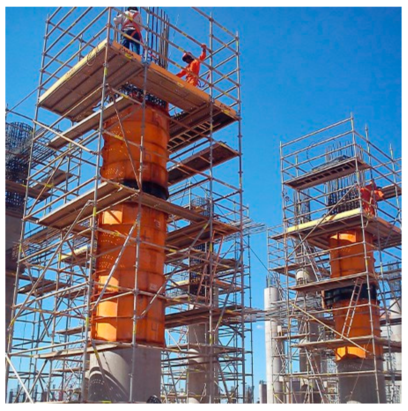
A conventional formwork acts as a temporary container for the wet concrete and supports the concrete’s wet weight and the live load of equipment and workers, as shown in Figure 1. Conventional scaffolding provides temporary access to structures under construction and acts as a supporting platform. Despite being the most common method, placing these components together takes time, can cause traffic congestion, and increases the construction cost. Another concern that can be faced in the field is the failure of formworks. It is possible that the design cannot be incorporated due to unexpected site conditions, and formwork failures can occur because of deviations from the original design [1]. Formwork failure can also occur due to possible human errors or the crushing of a wooden surface where the heavy loads are placed if the bearing surface of the joints is not appropriate. Based on the “Use and Re-use of Formwork: Safety Risks and Reliability Assessment” report, the re-used formwork is not factored into its design, and since it is subjected to a wide range of loads and exposures, it can experience possible degradation in its structural capacity. Furthermore, the failure of formwork can also occur during concrete pours and can cause concrete leaking, the failure of formwork components, complete structure collapse, and serious injuries or deaths [2]. Possible failures of formwork can be caused by mistakes during erection, wrong calculations of weight acting on the formwork, extra loads, or natural disasters [3]. Several worker interviews were conducted in order to establish the most common hazards on construction sites caused by falsework [4]. They have concluded that the main cause of formwork and falsework accidents on sides is due to the lack of planning, stripping of formwork, falling objects, floor collapse, and mishandling of material. Scaffoldings are temporary structures that companies build very quickly. However, this often means that they are erected without enough planning.
To prevent possible hazards of formwork and scaffolding failure, a new concept is developed by the third author using ultra-high performance concrete (UHPC) to construct a prefabricated shell that acts as a permanent stay-in-place form for bridge elements. The prefabricated shell is intended to eliminate the conventional formwork and scaffolding while reducing the on-site construction time and acting as a durable protective layer against the environmental attacks for normal concrete.
UHPC represents a durable material that allows the construction of innovative structural elements, while also meeting accelerated bridge construction (ABC) goals. UHPC contains a combination of Portland cement, fine sand, silica fume, high-range water-reducing admixture (HRWR), steel fibers, and water. Non-deformable, cylindrical steel fibers in the UHPC mixture have a diameter of 0.2 mm and length of 12.5 mm. Steel fiber proportion ranges from 2% to 4% by volume. Cementitious-based composite material, containing steel fiber reinforcement, is able to reach compressive strength above 150 MPa and tensile strength above 5 MPa, which is more than five times the compressive strength and around two times more than the tensile strength of conventional concrete [6]. UHPC material is known to possess greater frost and decaying salt resistance, a lower rate of carbonation, and higher chloride resistance in comparison to normal strength concrete. Thus, structures made from UHPC unsurprisingly have lower maintenance and repair cost in the future [7].
Currently, the most popular application of UHPC in bridge construction is in connections between Prefabricated Bridge Elements and Systems (PBES). Advantages of prefabricated elements include a better quality of components, safety during construction, and reduced construction time. However, connections between these elements and adjacent bridge elements represent weak links, which are typically connected with interlaced reinforcing bars, and connectors or studs. Since these connection regions are critical parts of the structure, UHPC can be used to make the connections feasible, while also obtaining less expensive connectors and possessing better performance than the typically used field-cast grout materials [8].
2. System Development
One of the most common factors causing bridges to be structurally deficient or functionally obsolete is the rapid deterioration of their substructure. Almost 10% of United States (U.S.) bridges are considered structurally deficient, and about 13.6% are functionally obsolete [9]. Using more durable material, specifically UHPC, and implementing it in precast elements will extend the service life of the substructure compared to the service life of a normal concrete substructure. Chloride penetration tests were conducted by Graybeal [8], which included ponding a 3% sodium chloride solution on the surface of the concrete. Once this solution has been on the UHPC surface for 90 days, penetration of the chloride into the concrete was determined. As expected, the higher concentration of the chloride ions was recorded at the surface. However, the amount of chloride that penetrated through the UHPC was very small. This research proves that the mechanical properties of UHPC should protect the bridge substructure from severe environments and corrosion for steel reinforcement due to carbonation. Other research has been done at Florida International University regarding the chloride penetration, focusing on the effect of corrosion macro cells that can develop between the normal strength concrete (NSC) substrate and the repaired region of the UHPC. Farzad et al. [10] states that the repair of concrete elements with UHPC will generally improve the bond strength between two materials, and together with UHPC of low permeability, will result in a more durable structure, improving its service life. This is accomplished by restricting the ingress of damaging agents, improving the sustainability of the repaired structure.
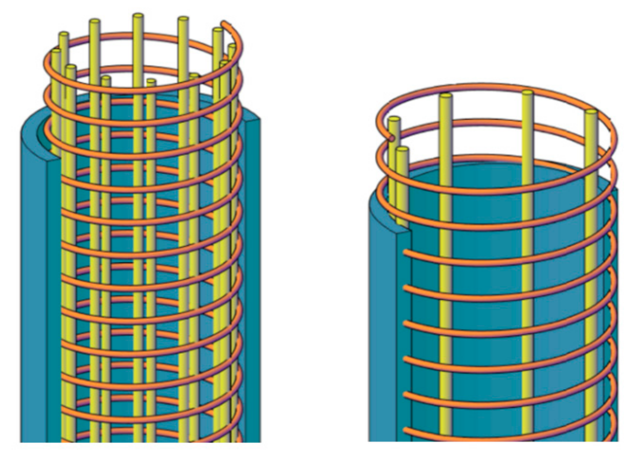
When a conventional reinforced concrete column is subjected to axial and lateral loads and moisture ingress through concrete due to corrosion and reinforcement causing the expansion of steel bars, cracks start to form, and the concrete cover spalls off. The area of the existing column section decreases along with its design strength. In order to prevent spalling, a prefabricated UHPC shell is being incorporated and tested on two specimens. The first specimen has no reinforcement embedded inside the UHPC shell, whereas a steel cage is provided for the normal concrete inside. Since the surface of UHPC is smooth once it is hardened, the friction between the conventional concrete and the shell is anticipated to be reduced, and the material might slip due to the excess loads. Due to this possible issue, the second specimen contains longitudinal bars partially embedded in the shell, and shared with column concrete. This detail reduces possible slippage, causing better bonding and interaction between the two materials. The shell also contains spiral reinforcement that is located around the longitudinal bars inside the shell, as shown in Figure 2.
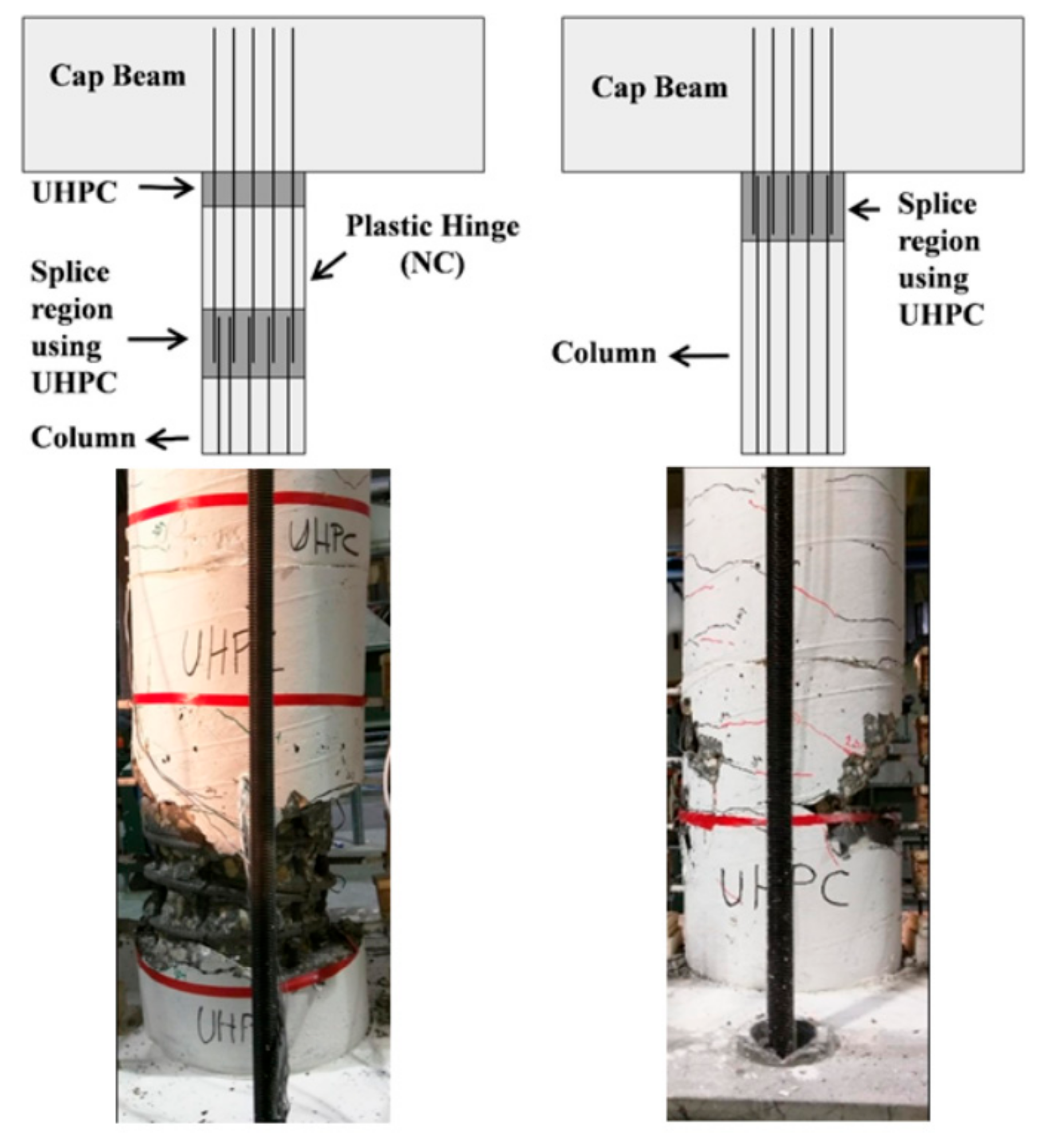
Furthermore, UHPC is also implemented in the connection between the footing and shell in order to decrease the length of the spliced bars and shift the formation of the plastic hinge above the critical section. Reinforced columns containing seismic and non-seismic details were tested, where UHPC was used as a connection for precast elements in the field. In the seismic detail, two layers of UHPC are incorporated, while in the non-seismic zone, only one layer was implemented, as shown in Figure 3 [11]. The formation of the plastic hinge was located between two layers of UHPC for seismic design and above the UHPC connection detail for non-seismic regions, proving that this advanced material can be used for shifting the plastic hinge location. Furthermore, the use of UHPC in the splice region was proven to be more effective along with decreasing the development length of the reinforcing bars [8].
3. Experimental Specimen
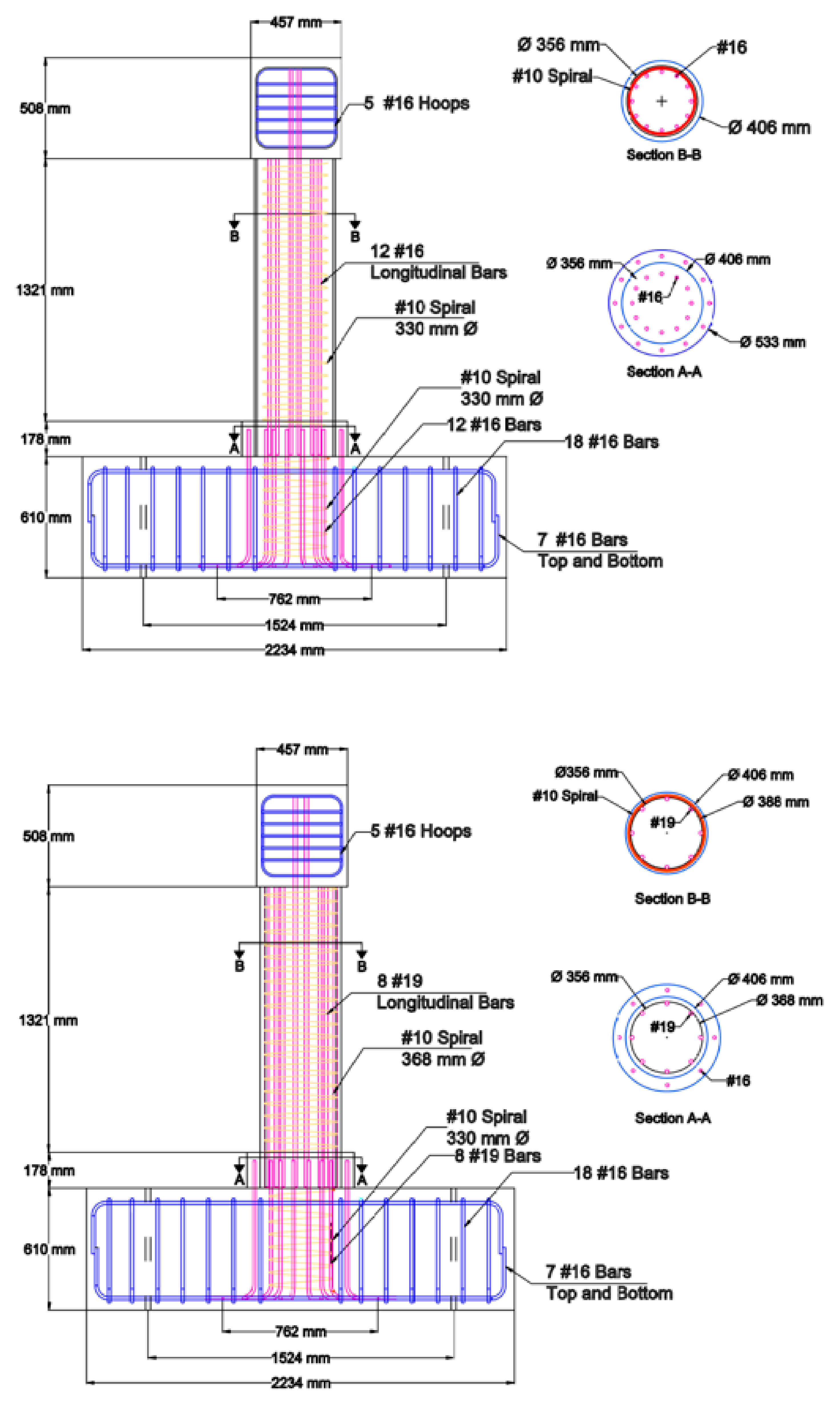
In this research study, two specimens are designed to be tested after the date of this publication. Several connection designs were considered in order to control the plastic hinge formation and interface between the UHPC shell and concrete column. The reinforcement details of both specimens are shown in Figure 4.
For the first specimen with a 406.4-mm diameter shell, 12#16 (15.9-mm diameter) longitudinal bars are used and spliced with the dowel bars from the footing. Another set of 12#16 (15.9-mm diameter) bars connect the footing with a UHPC step that has a height of 177.8 mm and a diameter of 533.4 mm. The lap splice length was chosen to be 127 mm based on eight times the bar diameter [8]. A spiral of 9.5-mm diameter (#10) was used as the transverse reinforcement in both the footing and column, but no reinforcement was provided in the UHPC shell. Since the UHPC surface is very smooth, another shell detail was proposed to increase the bond between the surface of the UHPC and the conventional concrete inside of the shell. To accomplish this connection, the column bar size was increased to enable it to be partially embedded in the UHPC shell, while also being exposed to the normal concrete inside. The new bar size for the second specimen was chosen to be #19 (19.1-mm diameter) instead of #16 (15.9-mm diameter), and the number of bars was reduced to eight bars instead of 12 bars, as shown in Figure 4, to maintain same moment capacity for both specimens, as discussed later. The lap splice length was chosen to be 152.4 mm based on eight times the bar diameter [8]. This specimen uses two different spirals of 9.5-mm diameter: one in the footing, and the other one inside the UHPC shell.
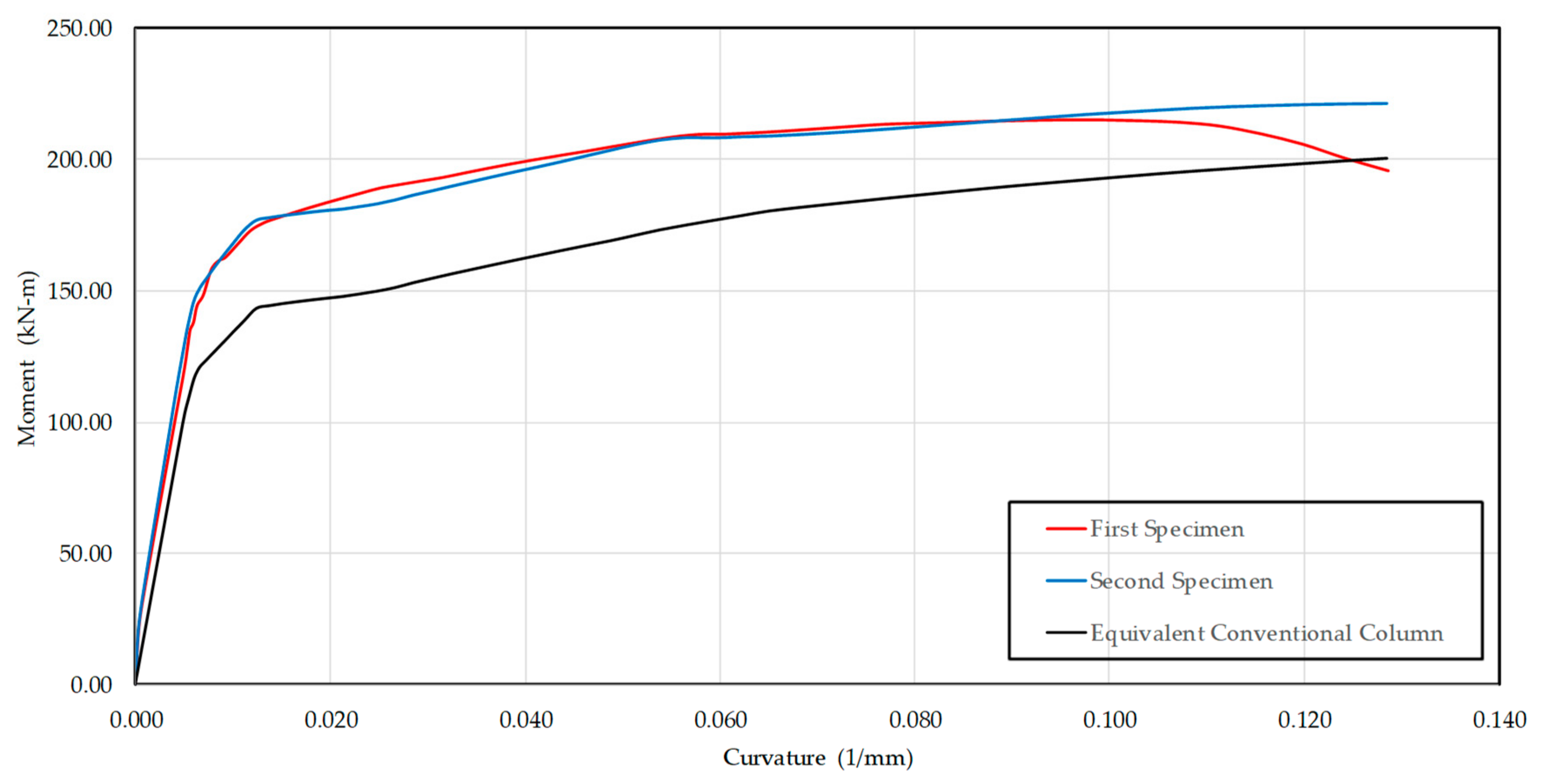
Since the specimens are yet to be tested, moment–curvature analyses were conducted on the column section (Section B-B in Figure 4), UHPC step section (Section A-A in Figure 4), and footing section of both specimens. Preliminary analysis was done in order to predict the failure region and shift the plastic hinge away from the footing in order to keep it as a protected element. Figure 5 presents moment–curvature plots for column sections of the two proposed specimens and an equivalent conventional column of the same diameter. From the plots, it can be concluded that the sections containing the UHPC shell shows higher moment capacity in comparison to the conventional section, with an increase of about 10%. The moment capacities of all three sections for both specimens are presented in Table 1, together with the moment ratios (UHPC step or footing moment capacity divided by the column moment capacity), showing that the failure was expected in the column section in both cases.
4. Specimen Construction
In this research project, two specimens were constructed that differed in the reinforcement detail in the UHPC shell and UHPC step element. Both specimens incorporated the precast shell element. The connection between the column and footing detail needed more attention since the plastic hinge formation was typically localized in that area.
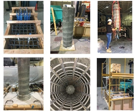
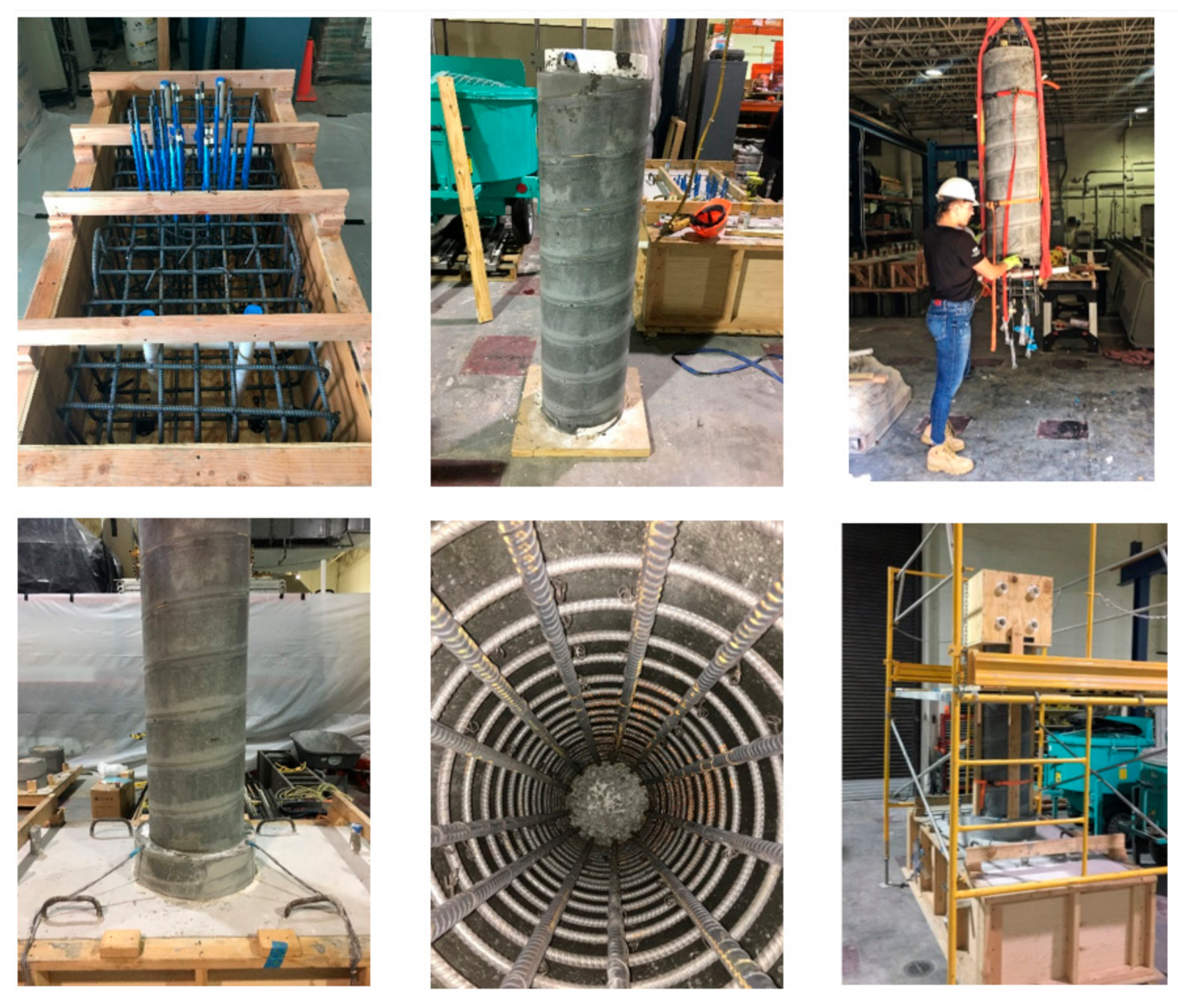
The first step of construction was making the footing and its reinforcement using conventional methods. The precast shell for the first specimen was shaped using a sonotube as the outside layer, and Styrofoam as the inside layer in order to shape the one-inch shell thickness. No reinforcement was embedded for this specimen; instead, the steel cage was placed later inside the shell as the reinforcement of the conventional concrete core. For the lab construction environment, the steel cage had to be placed in the shell prior to its placement on the footing. Thus, both elements were lifted together and placed on the footing, where the steel cage was spliced with the dowels in the footing. Once the splicing was completed, the shell was released to sit over the footing and the UHPC step was cast inside a 406.4-mm diameter sonotube with a height of 177.8 mm. The concrete for the column core and cap beam was poured after the UHPC in the step had hardened; then, the shell and steel reinforcement were stable, as shown in Figure 6. Construction steps for the first specimen
The second specimen was designed with two main differences in comparison to the first specimen. First, the longitudinal bars were designed to be partially embedded in the UHPC shell while being exposed to the normal concrete core to develop a better bond, as discussed earlier. Second, the transverse reinforcement was designed with a spiral located around the longitudinal bars and completely embedded in the shell. Due to this placement of the column reinforcement, the bars used in the first specimen, which connect the UHPC step to the footing, were reduced from 12#16 bars to 8#16 bars. However, the UHPC step details remained the same, in order to investigate different connections.
5. Test Setup and Loading Protocol
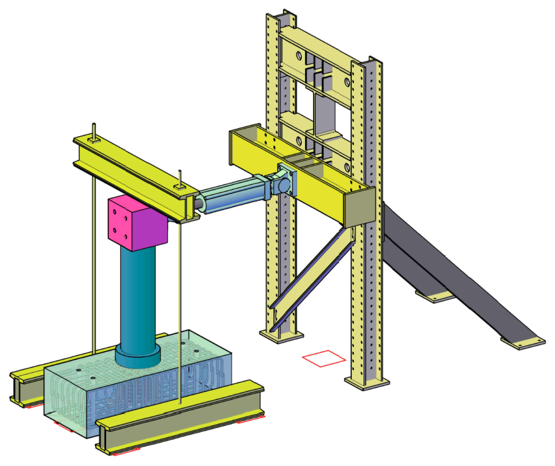
In this research project, both specimens were being tested under combined incremental lateral cyclic loading using a 490-kN hydraulic ram and constant axial load using two hydraulic jacks located on a horizontal spreader steel beam. The hydraulic ram used for lateral displacement was located on a steel beam bolted to the two-column frame on the north side, as shown in Figure 7.
A cantilever model type was used, where the inflection point of both columns was assumed to be at mid-height. In this case, the damage was concentrated at the plastic hinge zones, which were located right above the UHPC step. Based on the test setup, the following values were typically obtained: the moment, rotation, curvature, and displacement ductility of the columns.
To determine the idealized yield displacement of the tested specimen, which was assumed to be a bilinear model, low displacement cycles were initially applied. An equivalent elastoplastic system was assumed for the yielding displacement (Δy) where the elastic stiffness and ultimate load were assumed to be the same as the real system. Once Δy has been found, the column was designed to be subjected to three cycles of 2Δy, 3Δy, 4Δy, and so on. After each cycle, the cracks were typically traced while also documenting the observed damage.
6. Instrumentation
The test setup is designed to contain load cells, strain gauges, strain pots, and GoPro cameras in order to monitor and evaluate the behavior of both UHPC shell columns, as shown in Table 2. Several different measurements and observations had to be made for the testing of both specimens, which included data for material properties, loading displacement graphs, cracking patterns, curvatures, and drift ratios. For the first specimen, 24 strain gauge sensors were installed at different locations: 12 inside the footing, and 12 on the longitudinal reinforcement of the column. The strain gauges in the footing are located right below the surface, on the dowel bars in the loading direction, where tension and compression in the bars are expected. Four strain pots are designed to be installed on the north, south, east and west sides of the footing in order to measure the displacement and curvature of the specimen using the chord length and chord angle with respect to the footing. Four GoPro cameras will be placed on all four sides of the specimen, simultaneously recording the displacement and sound of the tested specimen for the damage monitoring.
7. Conclusions
The use of UHPC material as the precast shell element and as material for the connection for the column-to-footing and column-to-cap beam connection details was investigated on two column specimens in order to increase the capacity of the system and minimize the formwork for bridge columns. A quasi-static load test is designed to be conducted for two columns to determine the bonding performance of the UHPC shell and conventional column concrete. The first specimen does not contain reinforcement between the UHPC shell and the column concrete, while the second specimen has longitudinal reinforcement shared between the UHPC shell and concrete column to provide additional bonding between the two materials. For both specimens, a UHPC step connection is provided in order to shift the plastic hinge away from the critical region and prevent the slippage of the shell in that area. The full experimental results and numerical analysis are planned to be reported in a technical paper, as this publication serves as a technical note to illustrate the concept and system development. It is expected based on the performance of UHPC that the UHPC shell protects the column concrete, enhances the column performance, reduces the construction time, and extends the service life of the proposed column.
Author Contributions
Concept Development: A.A.; Investigation: N.C., I.M. and A.A.; Lab Work: N.C.; Supervision: I.M. and A.A.; First Draft: N.C.; Paper Writing: N.C.; Paper Writing Review: I.M.; Final Paper Review: I.M. and A.A.
Funding
This research was funded by Accelerated Bridge Construction-University Transportation Center (UTC-ABC).
Conflicts of Interest
Authors declare no conflict of Interest.
References
- Infrastructure Health & Safety Association (IHSA). Construction Health and Safety Manual; Chapter 42; IHSA: Mississauga, ON, Canada, 2017. [Google Scholar]
- Barbosa, A.; Gambatese, J.; Das, A.; Pestana, A.C. Mapped Workflow for Safety and Reliability and Reliability Assessments of Use and Reuse Formwork. In Proceedings of the Construction Research Congress 2014, Atlanta, GA, USA, 19–21 May 2014; The Center for Construction Research and Training: Silver Spring, MD, USA, 2017. [Google Scholar]
- Vibin, R.; Ilango, S.P. Risk Assessment and Safety in Formwork. Presented at the Two Day National Conference on Civil Structure and Environmental Engineering, Chennai, India, March 2015. [Google Scholar]
- Mothokho, L.; Emuze, F.; Aka, A. Formwork and Falsework Hazards in Construction: Status and Effects in Bloemfontein, South Africa. In Proceedings of the 2015 (6th) International Conference of Engineering Project, and Production Management, Gold Coast, Australia, 2–4 September 2015; Ejdys, J., Chua, D., Smallwood, J., Eds.; Griffith School of Engineering: Gold Coast, Queensland, Australia, 2015. [Google Scholar]
- CLR Circular Column Formwork. Available online: Uni-span.com.au/product/clr-circular-column-formwork/ (accessed on 18 March 2019).
- Haber, B.; De La Varga, I.; Graybeal, B.; Nakashoji, B.; El-Helou, F. Properties and Behavior of UHPC-Class Materials; No. FHWA-HRT-18-036; United States Federal Highway Administration, Office of Infrastructure Research and Development: Georgetown Pike McLean, VA, USA, 2018.
- Graybeal, B. Material Property Characterization of Ultra-High Performance Concrete; No. FHWA-HRT-06-103; Federal Highway Administration, Office of Infrastructure Research and Development: Georgetown Pike McLean, VA, USA, 2006.
- Russell, H.; Graybeal, B. Ultra-High Performance Concrete: A State-of-the-Art Report for the Bridge Community; No. FHWA-HRT-13-060; Federal Highway Administration, Office of Infrastructure Research and Development: Georgetown Pike McLean, VA, USA, 2013.
- The Architects Newspaper. Available online: https://archpaper.com/2018/08/bridge-maintenance-us/ (accessed on 18 March 2019).
- Farzad, M.; Fancy, S.F.; Lau, K.; Azizinamini, A. Chloride Penetration at Cold Joints of Structural Members with Dissimilar Concrete Incorporating UHPC. Infrastructures 2019, 4, 18. [Google Scholar] [CrossRef]
- Shafieifar, M. Alternative ABC Connecting Precast Column to Cap Beam Using UHPC; University Transportation Center: Miami, FL, USA, 2018. [Google Scholar]
Figure 1.
Work on circular columns using formwork and scaffolding [5].
Figure 1.
Work on circular columns using formwork and scaffolding [5].

Figure 2.
Placement of reinforcement in Specimen 1 (left) and Specimen 2 (right).

Figure 3.
Previous seismic and non-seismic details incorporating ultra-high performance concrete (UHPC) to shift plastic hinge regions away from the connection [11].
Figure 3.
Previous seismic and non-seismic details incorporating ultra-high performance concrete (UHPC) to shift plastic hinge regions away from the connection [11].

Figure 4.
Reinforcement detailing for Specimen 1 with a smooth UHPC shell surface (top) and Specimen 2 with reinforcement shared between the UHPC shell and column concrete (bottom).
Figure 4.
Reinforcement detailing for Specimen 1 with a smooth UHPC shell surface (top) and Specimen 2 with reinforcement shared between the UHPC shell and column concrete (bottom).

Figure 5.
Moment–curvature curves for the column section of each specimen and an equivalent conventional column.
Figure 5.
Moment–curvature curves for the column section of each specimen and an equivalent conventional column.

Figure 6.
Construction steps for the first specimen.

Figure 7.
Test Setup for both specimens.


Table 1.
Moment capacity of each section for the first and second specimen and their ratios.
| Column Section | UHPC Step Section | Footing Section | |||
|---|---|---|---|---|---|
| Moment, M1 (kN∙m) | Moment, M2 (kN∙m) | Ratio M2/M1 | Moment, M3 (kN∙m) | Ratio (M3/M1) | |
| Specimen 1 | 214.99 | 680.68 | 3.17 | 461.81 | 2.15 |
| Specimen 2 | 221.62 | 596.50 | 2.69 | 461.81 | 2.08 |
Table 2.
Instrumentation summary.
| Instrumentation | Count |
|---|---|
| Displacement Strain Pots | 1 |
| Column Curvatures Strain Pots | 4 |
| Longitudinal Reinforcement Strain Gauges | 12 |
| Dowel Reinforcement Strain Gauges | 12 |
| Actuator Load Cell | 1 |
| GoPro Cameras | 4 |
© 2019 by the authors. Licensee MDPI, Basel, Switzerland. This article is an open access article distributed under the terms and conditions of the Creative Commons Attribution (CC BY) license (http://creativecommons.org/licenses/by/4.0/).
Share and Cite
MDPI and ACS Style
Caluk, N.; Mantawy, I.; Azizinamini, A. Durable Bridge Columns using Stay-In-Place UHPC Shells for Accelerated Bridge Construction. Infrastructures 2019, 4, 25. https://0-doi-org.brum.beds.ac.uk/10.3390/infrastructures4020025
AMA Style
Caluk N, Mantawy I, Azizinamini A. Durable Bridge Columns using Stay-In-Place UHPC Shells for Accelerated Bridge Construction. Infrastructures. 2019; 4(2):25. https://0-doi-org.brum.beds.ac.uk/10.3390/infrastructures4020025
Chicago/Turabian StyleCaluk, Nerma, Islam Mantawy, and Atorod Azizinamini. 2019. "Durable Bridge Columns using Stay-In-Place UHPC Shells for Accelerated Bridge Construction" Infrastructures 4, no. 2: 25. https://0-doi-org.brum.beds.ac.uk/10.3390/infrastructures4020025