Review

Fiber Optics Sensors in Asphalt Pavement: State-of-the-Art Review

1
EMIB Research Group, Faculty of Applied Engineering, University of Antwerp, 2020 Antwerp, Belgium
2
Com&Sens, 9810 Nazareth, Belgium
3
Op3Mech Research Group, Faculty of Applied Engineering, University of Antwerp, Groenenborgerlaan 171, 2020 Antwerp, Belgium
4
Port of Antwerp, Zaha Hadidplein 1, 2030 Antwerp, Belgium
5
Agency for Roads and Traffic, 1140 Evere, Belgium
*
Author to whom correspondence should be addressed.
Submission received: 15 May 2019 / Revised: 13 June 2019 / Accepted: 14 June 2019 / Published: 20 June 2019
(This article belongs to the Special Issue Recent Advances and Future Trends in Pavement Engineering)

Abstract

:
Pavement design is essentially and usually a structural long-term evaluation process which is needed to ensure that traffic loads are efficiently distributed at all levels of the total road structure. Furthermore, to get a complete analysis of its durability behavior, long-term monitoring should be facilitated, not only from the top by falling weight deflectometer (FWD) or core drilling but preferably from inside the structure and at exactly the same positions during a long-time interval. Considering that it is very hard to devise an efficient method to determine realistic in-situ mechanical properties of pavements, the determination of strain at the bottom of asphalt pavement layers through non-destructive tests is of a great interest. As it is known, fiber Bragg grating (FBG) sensors are the most promising candidates to effectively replace conventional strain gauges for a long-term monitoring application in a harsh environment. The main goals of this paper are to compile an overview of the recent developments worldwide in the application of fiber optics sensors (FOS) in asphalt pavement monitoring systems; to find out if those systems provide repeatable and suitable results for a long-term monitoring; if there are certain solutions to validate an inverse modelling approach based on the results of FWD and FOS.

Graphical Abstract

1. Introduction

Pavement design is essentially and usually a structural long-term evaluation process which is needed to ensure that traffic loads are efficiently distributed at all levels of the total road structure. The total road structure consists of a top layer, one or more base layers, subbase and subgrade. The stresses and strains developed at those levels should be within the capabilities of the materials used. The objective of the pavement design is to produce an engineering structure that will distribute traffic loads efficiently within the selected burden parameters by minimizing the whole-life cost of the pavement including the work costs (materials, construction, maintenance and residual value); the user costs (traffic delays, accidents at roadworks, skidding accidents, fuel consumption/tire wear and residual allowance); environmental impact and so forth. Mechanical pavement design usually involves the selection of the materials/mixtures for the different layers of the pavement structure and the calculation of the required thickness of the designed pavement. Stiffness is a fundamental and important parameter that must be fully understood in the selection of the materials. Usually pavement layers have a higher stiffness while the layers underneath such as base and subbase have a greater thickness with a lower stiffness to get the same pressure on the underside. The thickness of the pavement structure layers can be reduced by increasing the stiffness of the layers and introducing multilayered pavement structures which are commonly used in, for example, Belgium, France and The Netherlands. One of the important facets of material behavior is the consideration of the situation where the layers are susceptible to moisture. If the area becomes saturated, the stiffness is reduced (normally imposed stresses taken by the dry material cause the layer to fail). For sure it can be avoided if drainage is installed in such a way that groundwater never reaches the pavement layers. Since moisture may affect the subgrade and the sub-base (and, also the base if it is unbound). Another one is a temperature monitoring, as temperature affects the bitumen-bound layers. It is essential that the design process takes the climatic conditions into account [1,2]. Also, the pavement compaction quality is a very important facet.
In the last 50 years, pavement research and related pavement techniques have grown. These theories, principles, and/or procedures which were based on the knowledge and research achievements at that time, have helped the pavement professionals to make specific analysis, design, construction and maintenance on pavements. Therefore, they have created a far-reaching influence on later pavement technology [3]. On the other hand, during the same period, a lot of new pavement materials were invented and widely used. The properties of these new materials are considerably different compared to the conventional materials. Neither traditional pavement analysis methods nor existing design principles can provide a direct way to consider these differences. This leads to the necessity and the difficulty of modifying the pavement design methods used so far. Currently, there are several important challenges to pavement research related to asphalt pavement analysis and design that include: how to deal with more and more common heavy traffic loads (the allowed max. weight for 5 axles to be 44 tons in Belgium and France and 50 tons in The Netherlands) [4], or even overloads and with increasing traffic volumes; how to consider emerging pavement materials; how to incorporate new materials, new techniques and new design concepts into pavement analysis and design; and how to consider ageing and healing effects.
The assessment of pavement mechanical state and service life is very important for design evaluation and road maintenance. However, this job seems to be a mission impossible, because it is unimaginable to learn how exactly a pavement works inside [5]. Conventional monitoring and investigation methods adopted by researchers are core drilling, pavement cutting, Benkelman beam, falling weight deflector (FWD), automatic deflectometer, surface-curvature apparatus and so forth. They are either destructive or with low-precision or low-frequency and most important is that all these methods are discontinuous and short-term. A pavement which is exposed for a long time to a natural environment, is deteriorating at the coupled effect of load, temperature, water and ultraviolet light. It is very difficult to completely understand the mechanical response of a pavement structure in an actual environment by regular methods [5]. In fact, pavement monitoring is a rather complicated process and each pavement is another case to survey. Furthermore, it cannot be monitored only for a short-term period to get a complete analysis of the pavement behavior.
The past two decades some major technological breakthroughs produced by the fusion of different disciplines have been witnessed. This trend is likely to develop in the future due to the recent significant advancements of fiber optics communications, photonics, biomedical and nanotechnologies worldwide. In parallel with the communications and information technology revolution, fiber and waveguide optics sensor and imaging technologies have enjoyed an unseen technological maturity and revealed enormous potentials for a broad variety of new applications [6].
Asphalt material is often considered to behave in a linearly viscoelastic-plastic manner; thus, its mechanical response is a continuous function of time and temperature. Considering the stiffness of the material, its behavior at lower temperatures is equivalent to a higher strain rate, such as the strain on pavement due to fast moving traffic. In the case of high stiffness, the strain on asphalt should ideally be measured directly for the greatest accuracy; however, instruments capable of making such measurements are not generally available. Electrical strain gauges are often assumed to have negligible stiffness and the stress transferred from the asphalt to an embedded sensor decreases drastically, thereby reducing the sensitivity of the sensor reading [7]. The sensors used for pavement instrumentation must be as much compatible with the heterogeneous nature and mechanical properties of pavement materials. First, the sensors should be as small as possible so that they are not too intrusive in the bituminous layers. Secondly for strain measurements, the stiffness of the sensors has to match that of the asphalt mixture in order to correctly measure the mechanical properties of the pavement. More-over, the embedded sensors must withstand the highest stresses experienced during the pavement construction process (high temperature and compression). After that, if a long-term monitoring is considered, the sensor should be resistant to corrosion and to thermo-mechanical fatigue conditions [8].
Several fiber optic sensor technologies (fiber Bragg grating (FBG) and Fabry-Perot (FP) interferometry) have already been used for the experimental investigation of pavement behavior and pavement monitoring with positive results. FBG is a small portion of an optical fiber several millimeters long in which a diffraction grating is written by ultraviolet (UV) exposure. The optical property of this grating is to reflect a narrow optical band (around a center wavelength called Bragg wavelength) of the incident spectrum. FBG have the intrinsic quality to be very sensitive to thermal and mechanical stimuli. The Bragg wavelength is proportional to the temperature and/or strain variation. Since, this sensor is very brittle, it needs to be packaged. The fiber FP sensor is essentially an optical cavity that is defined by two semi-reflecting parallel mirrors. The FP cavity (at least in a bulk optic form) has highly reflecting mirrors of reflectivity such that the device has a high finesse and consequently its reflection/transmission is spectrally selective and serves as an interference filter element. In its use with optical fibers, the cavity is formed in a short length (1–30 mm) of optical fiber that has partially reflecting coated ends which is then fusion-spliced onto the end of the connecting fiber [9]. Those technologies allow to perform dynamic measurements at a sampling rate of at least of 0.5–1 kHz (for the standard interrogators), they are investigated particularly for the development of traffic classification and weigh-in-motion systems. In particular, FBG sensors have been widely applied in different sensing fields, where they are used as strain and temperature sensors [10,11,12,13], for deformation investigation [14,15,16], rutting performance [17,18], response of asphalt concrete [19,20] and weigh-in-motion [21]. Compared with conventional sensors, FBG sensors are the most promising candidates to effectively replace conventional strain gauges for long-term real-time monitoring applications in a harsh environment. They exhibit several advantages: flexibility, embeddability, high frequency, electromagnetic interference immunity and so forth. FBG and FP technologies deliver a strain local measurement like an electrical strain gauge. Despite their high sensitivity and accuracy, they are not suitable for detection of cracks or damage. Due to their relatively small dimensions compared to those of a pavement, a crack can be detected only if it propagates in the vicinity of the sensor, by means of fiber optic sensing techniques based on the Brillouin scattering or the Rayleigh scattering [8].
The FBG monitoring system prototype installed at UAntwerp—a three-layered pavement test track (width—4 m and length—96 m), the CyPaTs bicycle path—in September 2017, proved that the FBG technique can be successfully applicable for in-situ strain and temperature measurements under real heavy loaded traffic (e.g., truck, paver, roller) in the asphalt pavement structures during the asphalt paving process [22,23,24,25,26]. It also proved that an FBG monitoring system can be functional for long-term pavement monitoring as it is still operational. Nowadays, the determination of strain at the bottom of asphalt pavement layers through non-destructive tests is of a great interest. Therefore, the application of FBG in an asphalt pavement structure can be considered as an advanced research method for a long-term and real-time process.
The main goals of this review are to compile an overview of the recent developments worldwide in the application of fiber optics sensors (FOS) in asphalt pavement monitoring systems; to find out if those systems provide repeatable and suitable results for a long-term monitoring; if there are certain solutions to validate an inverse modelling approach based on the results of FWD and FOS. Section two gives an overview of the standardized FWD methodology compared to several test cases using fiber optics sensors in asphalt pavements. The results of the inverse modeling approach performed by several researchers using FOS and FWD are described in section three. A concluding summary on the application of FOS to determine tensile strain at the bottom of an asphalt layer is given in Section 4.

2. Testing Methods and Technologies

This part of the review describes the standardized FWD methodology and several cases of application of FOS in asphalt pavement as an alternative method to FWD to determine tensile strains at the bottom of the asphalt layer.

2.1. Falling Weight Deflectometer

FWD is by now one of the most common non-destructive testing methods to assess bearing capacity on major road infrastructures by using deflection data generated from a loading device to quantify the response of a pavement structure to known load drops [27,28]. This non-destructive technique allows measuring the deflection response of the pavement at several positions under a given load (Figure 1). The surface deflections obtained from FWD testing are used to back-calculate in situ material properties using software which has been developed in the eighties [29]. These properties are considered representative for the pavement response to a load and can be used to assess stresses and strains that are valid for pavement structural and fatigue analysis and design. However, the accuracy of the results (stresses and strains at critical locations in the pavement) depends upon the assumptions used for the analysis [30].

2.2. Fiber Optics Sensors

Pavement monitoring is an essential part of pavement research and plays an important role in pavement management systems [32]. It is known that it is very hard to devise an efficient method to determine realistic mechanical properties of the asphalt pavement. Several gauges were developed to instrument the pavement for its monitoring but considering their high sensitivity to a lot of parameters, not many succeeded to obtain real-time strain data [33] as an alternative method for traditional FWD. FOS gained popularity in the last two decades when an attempt was made to instrument FOS inside the pavement for monitoring purposes. FOS is not commonly used in asphalt technology due to its application restrictions during rough construction processes, which require the sensors to endure high temperatures, moisture, high compaction force, repeated heavy loading and so forth. The accurate measurement of the pavement responses (strain and stress) distributions in pavement structure, combined with temperature, is critical for the understanding of pavement behavior and the modeling of pavement failure [32]. It was noted by Papavasiliou & Loizos [28] that implementing a FOS system is a time consuming and delicate procedure but it has proved to be a useful and promising tool for in-situ strain measurements under real traffic loading; however, due to the deviations between calculated strains (pavement design, FWD data analysis) and FOS signal records (measured strains) more experimental work was needed.
Below several cases of application of FOS in asphalt pavements are discussed in further detail.

2.2.1. Fiber-Optic Strain Gauge (2007) (Laval University, Canada)

The proposed gauge/instrumented core relates to horizontal strain measurements at the bottom of bound surfacing layers of pavements [34,35]. The gauge is designed to be retrofitted in existing pavement surfacing layers (asphalt concrete, Portland cement concrete or other bound material) through a small diameter core hole to minimize perturbation to the pavement layer to be instrumented. Fiber optic strain sensors are imbedded in the polymeric proof body. Even though electric strain gauges can be used for the proposed application, fiber optic sensors are preferred due to their insensitivity to water, frost action and electric fields. Figure 2 shows the schematic design of OpSens interferometric fiber optic strain transducer.
The sensor is made of two optical fibers that are precisely aligned inside a microcapillary tube to form an optical FP sensing interferometer. This makes the strain gauge completely immune to any electromagnetic interference and completely insensitive to transverse strains and temperature, as opposed to fiber optic Bragg gratings sensors.
Figure 3 shows a schematic illustration of an instrumented core which includes two measurement levels. Inside each polymeric proof body, two orthogonal fiber optic sensors are inserted (dash lines) for measuring the strain along the longitudinal and the transverse directions of the road. The polymeric proof body is made of a plastic composite having an elastic modulus and a thermal coefficient of contraction like asphalt concrete, allowing both materials to be mechanically compatible. The material is sufficiently robust to protect the gauge when the core is subjected to heavy traffic loads and severe climatic conditions.

2.2.2. Fiber-Optic Strain Gauge (2007) (National Technical University of Athens, Greece)

The system is based on the FP sensor type, which consists of two semi-reflective mirrors facing each other [37,38,39]. The mirrors are placed on the tips of multimode optical fibers, which are spot-fused into a capillary. The air gap between the mirrors defines the FP cavity to minimize disturbances to the stress fields around the gauge when the pavement was subjected to loading by heavy vehicles. It was also designed to allow for the installation of two orthogonal strain sensors allowing for the measurement of longitudinal and transversal strains at the bottom of the bound layer. The proof body and consequently the sensor were instrumented in the laboratory at the critical fatigue locations of the cores previously drilled from the test sites. The gauge was installed in the pavement by placing it and gluing it at the desired location in the core hole. The diameter of the cores was less than 10 cm, to minimize any disturbances to the pavement layers being instrumented.

2.2.3. Telecom Fiber Optic Cable as Distributed Sensor (2014) (IFSTTAR, France)

A new non-destructive technique for the detection of cracking in asphalt pavements was tested at a real scale on the pavement fatigue carousel of French Institute of Science and Technology for Transport, Development and Networks (IFSTTAR), which is a large scale circular outdoor facility, unique in Europe by its size (120 m length, 6 m width) and loading capabilities (Figure 4) [8,40]. It was based on the use of a telecommunication fiber optic cable embedded in the pavement layer as distributed sensor. An optical interrogator based on the Rayleigh scattering was used to measure strain profiles. The main advantage of this technique is that it allows to measure strains over a long length of fiber optic with a high spatial resolution, less than 1 cm. By comparing strain profiles measured at different times, an attempt was made to link strain changes with the appearance of damage (cracking) in the pavement. A significant increase of strains was detected by the optical fibers at different points in the pavement structure, before any damage was visible [8].
However, it must be mentioned here, that the main disadvantage of telecommunication fibers application is its limitation (up to few Hz) in sampling frequency. It is not possible to use the sensing system if determination of eigenfrequencies or performance of dynamic testing on a structure is needed. It is only useful to measure static long-term effects. In regard to FBG sensing systems, it is possible to perform low sampling frequencies for a long-term effect (e.g., creep, permanent deformation) and it is also possible momentarily to go higher in read out frequency to perform dynamic testing or investigate local fast relaxation effects and so forth. Standard telecommunication fibers are very fragile and are not suitable for direct embedding in the asphalt. As such cable design becomes very important, moreover also with respect to strain transfer and intrusiveness in the case cable diameters exceed 2 mm.

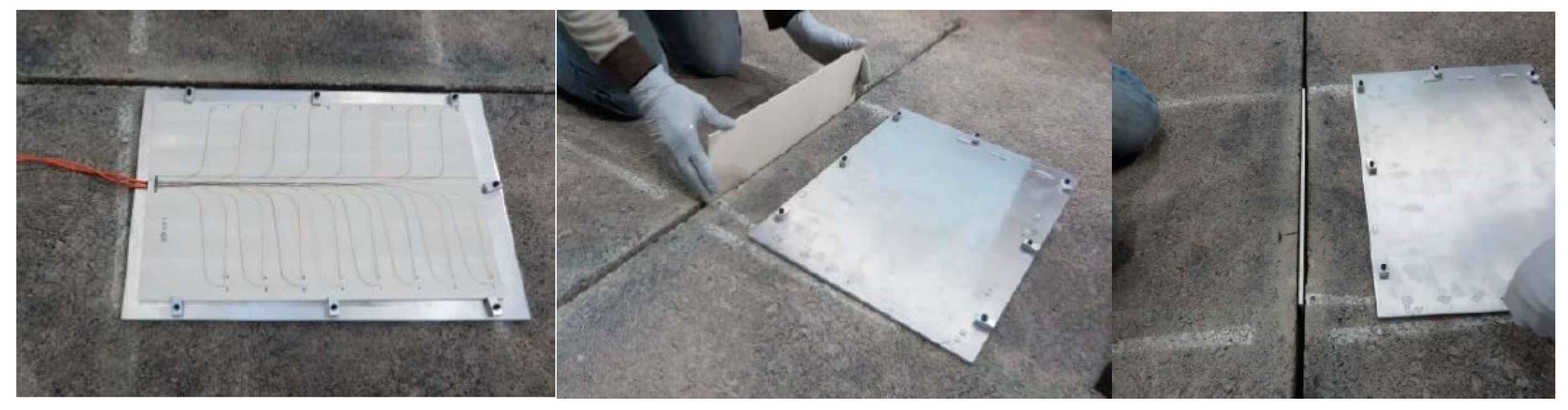
2.2.4. Fiber-Optic Strain Plate (2014) (Federal Aviation Administration, USA)

To measure the strain response under traffic load, four test pavement sections were instrumented with an innovative polymeric plate technology [41,42,43,44] at the Federal Aviation Administration (FAA) National Airport Pavement Test Facility (NAPTF) in Atlantic City, New Jersey, USA in 2014 (Figure 5) [45]. Each test section was equipped with one instrumented plate positioned perpendicularly to traffic direction. Each plate consisted of a polyphenylene sulphide (PPS) with a rectangular thin body in which 24 fiber optic strain gauges were embedded and bonded with epoxy. The fiber-optic strain gauges working principle is based on the White Light Polarization Interferometry (WLPI) technology. WLPI uses a signal conditioner to sense the path length difference inside a FP interferometer of a known cavity length and delimited by two dielectric mirrors [34].
With proper calibration, the path length difference can be related to engineering values, such as displacement, stress and strain. Three signal conditioners equipped with 8 channels were used to collect the data of the 24 gauges on one plate. The signal conditioner sends and receives the light and the software interprets and transforms the received signal into physical quantitative values. These values are compiled in a text file at a specified frequency (a 500 Hz data collection frequency was used).

2.2.5. FOS Monitoring System (2014) (Japan)

A full-sized field test was conducted on a slope of an under-construction asphalt-faced dam in 2014 [7]. Four types of sensor installation techniques were executed to embed flexible sensors which were simply coated with polyethylene for direct embedding in an asphalt structure on the asphalt slope (see Figure 6); each sensor had two lines along the slope due to the turning back at the bottom. All four sensor types were placed on the designated location, fixed with a solvent-type primer and covered with an asphalt mortar or sealant to be protected from a supply cart which carried the asphalt mixture (approximately 20 tons in total) over the sensors. Since the used sensors did not have a tension member, which is commonly used as reinforcement in conventional optical communication cables, FOS was expected to keep its sensitivity even if the asphalt exhibits low stiffness. Once the tension member reinforces the sensor itself, the sensor’s behavior would not comply with the flexible asphalt structure. In such case, the fact that the transferred stress from the asphalt to the sensor is drastically decreased accordingly leads to low sensor sensitivity. With the aim of flexibility and protection, a thermoplastic polyester elastomer-jacketed optical fiber with a diameter of 0.9 mm was directly coated to a diameter of 5 mm with adhesive polyethylene. Hence, the inner sensing element that is in the center of the fiber with a diameter of 0.25 mm behaved in the same way as the surrounding asphalt through the coating and jacket. A preliminary installation test on the hot mix asphalt fabrication, that is, compacted with aggregates at over 170°C, confirmed that the embedded FOS successfully survived. Also, FOS positioned in a trench of a lower layer was found to survive a heavy machinery construction. Though, only three sensor types out of four have survived the asphalt construction.

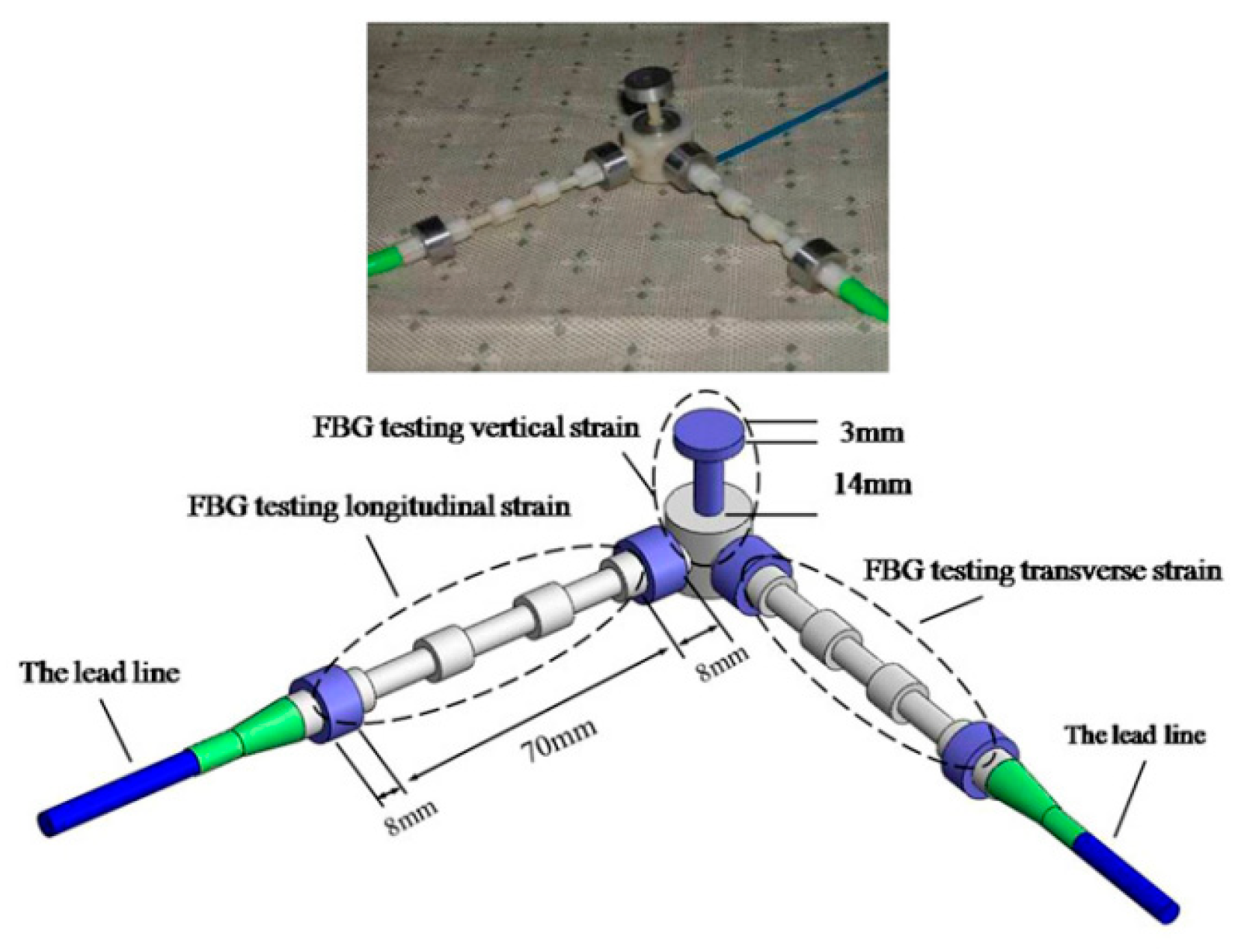
2.2.6. Asphalt Pavement Structural Health Monitoring with FBG Sensors (2012–2014) (China)

Optical fiber Bragg grating (OFBG) sensors to monitor the 3D strain of an asphalt layer were installed in a highway system in China [46]. Figure 7 shows the proposed sensors which have been assembled in three-dimension by a fiber reinforced polymer (FRP) connection, which has one inset hole for the vertical sensor and two spiral outshoots for the installation of the two transverse sensors. The short-gauged sensor is intended to monitor the vertical strain and the long-gauged ones are used to monitor the horizontal strains of the host structure. Reflective optical fiber Bragg grating signals from all of the three strain sensors are monitored in real time by an optical signal analyzer (OSA) and recorded by the computers for post data processing.
The project was elaborated in Jilin (China) with the aim: to measure the vertical compressive strain at the top of subgrade, the transverse tensile strain at the bottom of asphalt layer and the vertical compressive strain at the middle of asphalt layer based on key mechanical information and position in flexible pavement [5]. During the FBG sensors installation all cables were bound to avoid loss of signal for being pulled up. Static compaction (without any vibration applied for first two times) was applied to protect sensors from a heavy-duty loading. This study gave an idea about possible pavement monitoring by means of FBG sensors.
Monitoring of the in-situ compaction of an asphalt pavement by means of FBG sensing technology was performed during road construction in China in 2014 [47]. Three measuring points about three kilometers away from each other were chosen. FBG sensors were embedded near the curb of the pavement which is usually not easy to compact. To assure the survival rate of FBG sensors, sensors were embedded in grooves with similar configuration like in research study of Dong et al. [5]. During the monitoring process, rollers were operated at a constant speed of 4.8 km/h; strain and compactness were tested and calculated to identify how many roller passes are necessary for the compaction procedure. To verify the accuracy of compaction quality, the density of the pavement materials was tested by drilling cores from the pavement each 30 m away from the measuring points. When the temperature of pavement dissipated to normal temperature, the response of the pavement was evaluated using a test truck with known weight. Results showed that a lager compactness of HMA would result in a smaller vertical deformation of the pavement under dynamic load. Results also showed that the elastic recovery of the material would be obviously seen in the deformation curve, which indicated that FBG sensing technology has a sufficient precision for monitoring the deformation of an asphalt pavement. FBG sensors embedded in asphalt pavement can also be used for long-term monitoring of pavement structural behavior and provide the basis data for timely maintenance of asphalt pavement.

2.2.7. Installation of FBG Sensors in Asphalt (2016) (ASPARi, The Netherlands)

In the ASPARi project (a research project lead by the University of Twente (The Netherlands) in cooperation with several road construction companies throughout The Netherlands (for more information—https://www.utwente.nl/en/et/trc/projects/aspari/) several experimental programs were carried out where FBG sensors were applied in asphalt pavement [48]. Some of the items that were investigated in this project included: (i) a practical way to install and protect the sensors; (ii) which parameters influence the values delivered by the FBG-sensors; (iii) whether thermal values could be compared with thermocouples; and (iv) the output of the FBG-sensors was investigated to be suitable for models which could be of added value for contractors (long-term performance, vehicle induced loads after the compaction process and the amount of energy used during the asphalting process). It was concluded that it is possible to install the sensors on the desired position in the asphalt. However, protection of the sensors is a more complicated task; some of the sensors were broken because of the experiments. Temperature sensors values deviated from the thermocouple’s ones, since some of the sensors were placed in a steel tube for protection. It was concluded that the FBG, partly due to its versatility, still proves to be a promising technology. However, there is still a lack of specific knowledge about deployment technology for the early stage of the asphalting process. Therefore, it was required that more research is conducted on the possible adaptation of the FBG by the road construction industry. As a result, the models to be developed in this research project had to wait until the input, which consisted of the data acquired from the FBG-sensors, could be more reliable, accurate and robust.

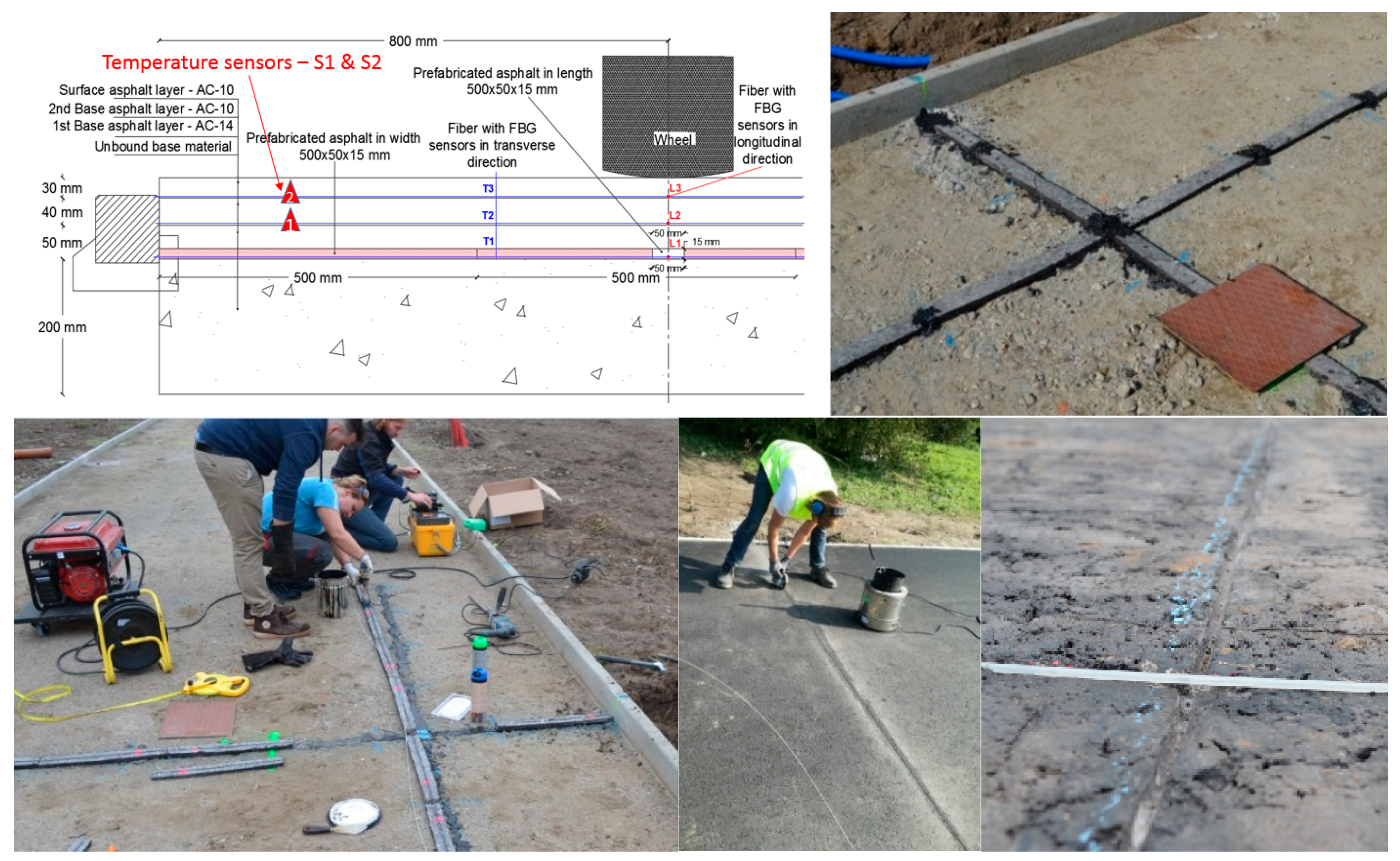
2.2.8. FBG Monitoring System (2017) (UAntwerp, Belgium)

Two new approaches to FBG sensors installation in three asphalt pavement layers were implemented for the first time in Belgium: (i) the installation of FBG sensors in prefabricated asphalt specimens with dimensions 50 × 15 × 500 mm with a 2 mm deep groove at the bottom of the specimen in the base layer, directly towards the base and (ii) the installation of FBG sensors at the surface of the previously constructed asphalt layer in 2 mm deep grooves. Both innovative approaches allowed the implementation of FBG sensors without sawing the whole layer into two parts. The installation of the FBG monitoring system prototype was a part of the project–CyPaTs, in which a bicycle path (length—96 m and width—4 m) was accomplished at UAntwerp in 2017 [49]. The installed FBG sensors were commercially available, organic modulated, ceramic-coated Draw Tower Gratings (DTG®) [50] with outer diameter of 0.2 mm, embedded in a glass fiber reinforced plastic (GFRP) round profile with an outer diameter of 1 mm and protected with an additional high-density polyethylene (HDPE) coating with outer diameter of 0.5 mm. The installed FBG monitoring system prototype consisted of several FBG chains: 2 fibers with 30 DTG® (spacing between sensors 10 cm) and 4 fibers with 5 DTG® (spacing between sensors 80 cm) and two temperature sensors (FBG based ~40 mm SS housing and ~1 mm diameter) embedded in three asphalt layers with a cross section configuration (width—4 m and length—3.2 m). The strain and temperature data were obtained using an interrogator FBG-SCAN 808D with 8 channels (1507–1593 nm wavelength range, 250 Hz measurement frequency for all channels). The FBG sensors configuration embedded in the three asphalt layers in both transverse and longitudinal directions at the bottom of each layer can be seen in Figure 8. All FBG sensors in all three asphalt layers survived during pavement construction. It was possible to learn how exactly pavement works inside during the pavement construction [22,23,24,25,26]. Fiber egress points were designed as such to come out at side of the pavement. Redundancy was built-in by the option to measure the strain wires from both sides. Monitoring of the FBG system was performed since the construction of the pavement. All sensing fibers were connected to a single mode multifiber (SMF) backbone cable to enable continuous monitoring from inside the building. This FBG system’s appliance as long-term monitoring system is possible and it can be installed, for example, in heavy-duty roads during their construction.
The same advanced UAntwerp FBG monitoring system—in collaboration with Port of Antwerp (Belgium) and Com&Sens (Belgium)—will be installed this summer in the Port of Antwerp to monitor a heavy-duty pavement in real-time and over the long-term.

3. Discussion

Pavement design is essentially and usually a structural long-term evaluation process which is needed to ensure that traffic loads are efficiently distributed at all levels of the total road structure. Furthermore, it cannot be monitored only for a short-term period to get a complete analysis of the pavement behavior. As shown in the selected literature, FBG sensors are the most promising candidates to effectively replace conventional strain gauges for a long-term monitoring application in a harsh environment.
This part of the review describes the outcome of the results if those systems provide repeatable and suitable results for a long-term monitoring and of the inverse modeling approach performed by several researchers from the above-mentioned research studies using FOS, strain gauges and FWD. It must be noted that only few studies made the comparison between the FOS strain results and the FWD measurements. Most of the studies were focused on the feasibility of applying FOS in pavement structures.
In the research group of NTUA, Greece [39] a FOS system was used for horizontal (tensile) strain measurements at the top and the bottom of a foamed asphalt (FA) layer. These locations were selected, considering the results of the strain response analysis based on back-calculated moduli at characteristic locations within the body of the recycled layer in a similar pavement structure. Tensile strains at these locations were critical in terms of possible fatigue failure and directly related to the performance of the pavement structure. Strain measurements were conducted with the FOS system during FWD loading (40 kN). In-depth temperature measurements were conducted with thermometers into drilled holes and using a single drop of glycerol, according to COST 336. Back-calculation of the recycled pavement layer moduli was carried out using MODCOMP© software (US). The horizontal (tensile) strains at the top as well as at the bottom of the foamed asphalt layer were calculated using finite-element linear analysis (FEA), using the ABAQUS© software (US). Compared to a much simpler multilayer elastic system analysis, the three-dimensional (3D) FEA was considered as more precise for the simulation of the FWD loading. The back-calculated moduli of the pavement’s layers were used as input for the forward FEA. Because the target of the analysis is the comparison of the calculated strains with the measured values, no adjustment of the back-calculated foamed asphalt moduli was conducted. The maximum measured tensile strains at the bottom of the FA layer, transversely or longitudinally, ranged from 6 to 15 με when applying FWD loading of 40 kN. The maximum calculated tensile strains (FEA) ranged from 19 to 34 με. The maximum measured tensile strains at the top of the foamed asphalt layer (respectively bottom of the asphalt layers), transversely or longitudinally, ranged from −10 to 7 με when applying an FWD loading of 40 kN. The maximum calculated tensile strains (FEA) ranged from 3 to 19 με. In all cases, the measured strains were lower than the relative calculated strains, indicating that the FEA overestimates the tensile strains, especially at the bottom of the FA layer. This discrepancy can be attributed to various sources of uncertainty during the calculations. There may also be errors and limitations in instrumentation design and installation that contribute to the mentioned differences [39]. It can be noted here that the strain measurements could also be underestimated or that the sensing system itself had influence on the material behavior. It was concluded that FWD can only be used as excitation to obtain tensile strain values of FA pavement materials by means of FOS. This outcome is promising towards the possibility of potential use of FWD for simulating the strain induced by a moving tire. However, as it was noted by Loizos et al. [39], more in situ data (measured strains) could lead to more reliable conclusions.
In the research group of University of Laval, Canada, it was noted by Bilodeau & Doré [31] that an existing alternative approach for determining the tensile strain occurring at the bottom of the asphalt concrete layer consists of bypassing the necessity of back-calculating the modulus of each layer by direct strain estimation from the deflection basin. In most cases, this approach overestimates the tensile strains occurring at the bottom of asphalt/concrete layers, leading to an underestimation of the pavement’s fatigue life. A model has been developed based on a theoretical analysis and a field calibration using data obtained at the Laval University experimental pavement site which allowed to compute tensile strain values that are in good agreement with tensile strain values obtained using theoretical models and, also with field measurements. The proposed approach to determine the tensile strain at the bottom of asphalt concrete layers using the deflection basin is based on Equations (1)–(3) to estimate the modulus of the mechanically involved layers, which are the asphalt concrete and base layers:
ε t model = H AC ( 0.199 + 3.868 × 10 2 log ( E AC ) 1.122 × 10 4 E base 8.627 × 10 3 H AC 2 R
log | E * | = 0.95 + 3.27 1 + e ( 2.67 0.51 log f + 0.07 T )
E base = [ 41.333 ln ( E AC ) 438.43 ] [ ln ( H AC ) 5.9877 ] + 50.683
in which HAC is the thickness (mm), EAC is modulus of the asphalt concrete layer (MPa), Ebase is the modulus of the aggregate base layer (MPa), | E * | is the dynamic modulus (MPa), f is the loading frequency (Hz) and T is the temperature (°C). To use the proposed model, the following values have to be obtained: temperature of the asphalt concrete, loading frequency of the FWD, deflection basin (d0 and d200 in mm), loading plate radius (mm) and thickness of asphalt concrete (mm). Therefore, the model is based on easily obtainable parameters and has a good prediction capacity. The tensile strains induced at the bottom of the asphalt concrete layer were measured with two different fiber optic strain gauges (asphalt concrete cores and plate). The FWD drops (40 kN) were applied directly on top of the sensors. The temperature was measured using a sensor located inside the asphalt concrete layer. Between the FWD tests, the temperature of the instrumented pavement zone was also controlled with a thermal blanket connected to two thermal baths controlling the circulated fluid temperature. An average loading frequency of 34 Hz was found for the FWD tests. A calibration factor of 1.87 is found between the model and the field conditions. This difference may be attributed to numerous factors, such as the difference between idealized modelling conditions, which were set for simplification reasons and non-ideal field conditions. As part of the field validation and calibration process, the objective was to identify a coefficient such as the one that was presented to consider the main differences between the model and the field conditions. Equation (1) allows the tensile strain to be determined at the bottom of the asphalt concrete layer as determined with finite element modelling using a combination of asphalt concrete thickness and modulus, base layer modulus, as well as using the deflection basin through the radius of curvature [31].
In the study of Primusz et al. [51], an approach was presented to define the modulus of the examined pavement layers, knowing the deflection curve and the thickness of the bound layer, without using further back-calculation. According to the performed research, there is a very strong correspondence between the E modulus of the bottom layer, the vertical deflection interpreted at the load axis and the radius of curvature of the pavement:
E = 1224.45 · D 0 1.623 · R 0 0.629
where D0 is the measured vertical deflection (mm), R0 is radius of curvature (m).
The objective of the study of Grellet et al. [44], as a part of a collaborative project between Laval University (Quebec City, Canada) and the IFSTTAR (Nantes, France), was to integrate viscoelastic properties in an asphalt pavement model in order to understand and predict the two types of cracking mechanisms: (i) initiated at the bottom of the asphalt layer and propagating toward the surface (bottom-up cracks); (ii) the second is initiated near the surface of the pavement and propagates downward through the bound layers (top-down cracks). The field tests have been conducted at the IFSTTAR’s accelerated pavement testing facility and at the SERUL (Laval University Road Experimental Site). Results from these studies showed that fiber optic sensors allowed adequately characterizing the strains occurring within the layer and evaluating the effects of the load configurations [43]. It was concluded in Grellet et al. [44] that a better pavement modeling is obtained using viscoelastic properties for the mechanical behavior of the asphalt layers and for the interface. Modeling the tack coat with a viscoelastic layer modifies the stresses and strain distribution through the layers and alters the prediction of pavement performance. Significant tensile stresses appear near the surface and could produce top-down cracking. The integration of the viscoelastic interface imposes a redistribution of the stresses through the layer. Tensile stresses increase near the surface and near the interface but decrease at the bottom of the layers. However, strains are higher considering the interface. The high extension strains (more than 250 με) have been measured at the bottom of the bituminous wearing course of a thin pavement structure at a high temperature (30°C) with a slow return of the strains to zero after loading.
The high tensile strains observed at high temperature at the bottom of the wearing course suggest that at high temperature, the interface with the lower layers cannot be considered as fully bonded and that some sliding between the wearing course and the base course occurs, generating these tensile strains. In other words, this means that the degree of bonding of the interface seems to change with temperature. This could be explained by the behavior of the tack coat (bitumen emulsion) at the interface; at high temperature, this emulsion presents a low stiffness, which reduces the shear resistance of the interface [51] It was stated that several temperature and load parameters must be evaluated to determine the most critical conditions.
An interesting outcome can be found in the study of Duong et al. [52], showing the results of the monitoring by means of strain gauges of an experimental pavement section recently re-constructed on a French motorway. The measurements showed that at high temperatures (above 30°C), high strain levels (150 με) are measured at the bottom of the bituminous layers. These strains exceed the limit fatigue strain, leading to failure for 1 million load cycles, determined using standard two-point bending fatigue tests, performed at 10°C and 25 Hz. Similar tests results had been obtained previously at IFSTTAR in accelerated pavement tests. Calculations were performed with the ALIZE-LCPC and Viscoroute programs (France), to fit the experimental strains, using elastic and viscoelastic pavement models. These calculations have shown that the pavement interfaces cannot be considered as fully bonded and that their level of bonding clearly changes with temperature. Different modelling cases have been tested and the best predictions have been obtained when modelling the interfaces as thin elastic layers (2 mm thick), with a low elastic modulus (in the range of 120 to 20 MPa for the range of low to high temperatures obtained on site). These interface layer moduli decreased when the temperature increased, and a particularly significant drop was observed between 25°C and 30°C with both ALIZE-LCPC and Viscoroute calculations. These results stress the fact that in pavement calculations, great attention should be paid to the modelling of pavement layer interfaces. These interfaces cannot be considered as fully bonded in all cases and in particular, their degree of bonding may decrease at high temperatures (above 30°C), where the stiffness of the tack coat at the interface becomes very low. This can lead to higher tensile strains at the bottom of the bituminous layers than predicted by standard design calculations, with bonded layers and thus to higher fatigue damage than predicted.

4. Conclusions

The most significant cases/attempts to perform experimental measurements with optical fibers in asphalt pavements in the last two decades have been included in this paper. Some of the main conclusions can be summarized as follows: the available technical information described mostly the attempts to install the FOS in the pavement; only a few studies provided technical details on the FOS installation; only a few cases could be referred to as long-term pavement monitoring; most of the cases envisaged more experimental measurements than monitoring of the pavement itself. Some suggested solutions were given to validate an inverse modelling approach based on the results of FWD and FOS. It can be concluded that the application of FOS in the asphalt pavement: (i) has proved to be a useful and a promising tool for in-situ strain measurements under real traffic loading at the bottom of the asphalt layers; (ii) it also proved that interfaces of the pavement structure cannot be considered as fully bonded, in particular, at high temperatures, although when using the standardized FWD methodology it is always considered that interfaces are fully bonded; (iii) instrumentation design and installation of FOS contributes to the differences in calculated and measured tensile strain values; (iv) due to the deviations between calculated strains (pavement design, FWD data analysis) and FOS signal records (measured strains) more experimental work is needed to define a calibration factor.

Author Contributions

Writing—original draft preparation, P.K.D.M.; Writing—editing, G.L., C.V., E.V. and W.V.d.b.; Writing—review, S.V., J.B., N.S. and J.D.W.

Funding

This research was funded by the Port of Antwerp (within the project “Duurzame Asfaltverhardingen voor zwaar belaste wegdekken”) and by the University Research Fund at the University of Antwerp through the project BOF/STIMPRO/36539 “Development of a novel optical signal processing method for analyzing data of the deformations of the asphalt construction by using Fiber Bragg technology to design new asphalt model,” supported by both the Road Engineering Research Section (EMIB) and Op3Mech research group.

Conflicts of Interest

The authors declare no conflict of interest.

References

  1. Read, J.; Whiteoak, D.; Hunter, R.N. The Shell Bitumen Handbook; Thomas Telford: London, UK, 2003; p. 460. [Google Scholar]
  2. Van Gurp, C.A.P.M. Characterization of Seasonal Influences on Asphalt Pavements with the Use of Falling Weight Deflectometers. Ph.D. Thesis, TU Delft, Delft, The Netherland, 1995. Available online: https://repository.tudelft.nl/islandora/object/uuid:596d5b28-308d-4c74-a3b8-cad632a93619?collection=research (accessed on 12 May 2019).
  3. Sun, L. Structural Behavior of Asphalt Pavements; Butterworth-Heinemann: Oxford, UK, 2016; p. 1070. ISBN 978-0-1280-2893-3. [Google Scholar]
  4. Permissible Maximum Weights of Lorries in Europe, International Transport Forum. 2015. Available online: https://www.itf-oecd.org/sites/default/files/docs/weights_0.pdf (accessed on 12 May 2019).
  5. Dong, Z.; Li, S.; Wen, J.; Chen, H. Asphalt pavement structural health monitoring utilizing FBG sensors. Adv. Eng. Forum 2012, 5, 339–344. [Google Scholar] [CrossRef]
  6. Bock, W.J.; Gannot, I.; Tanev, S. Optical Waveguide Sensing and Imaging, NATO Science for Peace and Security Series-B: Physics and Biophysics; Springer: Dordrecht, The Netherlands, 2008; p. 269. [Google Scholar] [CrossRef]
  7. Imai, M.; Igarashi, Y.; Shibata, M.; Miura, S. Experimental study on strain and deformation monitoring of asphalt structures using embedded fiber optic sensor. J. Civ. Struct. Health Monit. 2014, 4, 209–220. [Google Scholar] [CrossRef]
  8. Chapeleau, X.; Blanc, J.; Hornych, P.; Gautier, J.-L.; Carroget, J. Assessment of cracks detection in pavement by a distributed fiber optic sensing technology. J. Civ. Struct. Health Monit. 2017, 7, 459–470. [Google Scholar] [CrossRef]
  9. Meggitt, B.T. Chapter 17-Fiber Optics in Sensor Instrumentation. In Instrumentation Reference Book; Boyes, W., Ed.; Butterworth-Heinemann: Oxford, UK, 2010; pp. 191–216. [Google Scholar] [CrossRef]
  10. Wang, J.-N.; Tang, J.-L.; Chang, H.-P. Fiber Bragg grating sensors for use in pavement structural strain-temperature monitoring. Proc. SPIE 2006, 6174, 61743S. [Google Scholar] [CrossRef]
  11. Luyckx, G.; Voet, E.; Lammens, N.; Degrieck, J. Strain measurements of composite laminates with embedded fibre Bragg gratings: Criticism and opportunities for research. Sensors 2011, 11, 384–408. [Google Scholar] [CrossRef] [PubMed]
  12. Geernaert, T.; Sulejmani, S.; Sonnenfeld, C.; Luyckx, G.; Chah, K.; Areias, L.; Mergo, P.; Urbanczyk, W.; Van Marcke, P.; Coppens, E.; et al. Microstructured optical fiber Bragg grating-based strain and temperature sensing in the concrete buffer of the Belgian supercontainer concept. Proc. SPIE 2014, 9157, 915777. [Google Scholar] [CrossRef]
  13. Luyckx, G.; Voet, E.; Grefhorst, R.; Peeters, J.; Degrieck, J. Long term monitoring of an all-composite water lock using fibre optics. In Proceedings of the SAMPE EUROPE 2016, Liege, Belgium, 13–15 September 2016. [Google Scholar]
  14. Liu, W.; Liu, X.; Wang, Z.; Zhi, Z. High temperature deformation investigation of asphalt mixture with nanosized volcanic ash fillers using optical fiber sensor. Measurement 2019, 140, 171–181. [Google Scholar] [CrossRef]
  15. Li, L.; Huang, X.; Wang, L.; Li, C. Integrated experimental and numerical study on permanent deformation of asphalt pavement at intersections. J. Mater. Civ. Eng. 2013, 25, 907–912. [Google Scholar] [CrossRef]
  16. Abe, N.; Mizukami, J.; Kimura, M. Influence of moving load to extend the deformation of asphalt pavement. In Proceedings of the 11th ISAP conference on Asphalt Pavements, Nagoya, Japan, 1–6 August 2010; pp. 1054–1063. [Google Scholar]
  17. Xie, J.; Li, H.; Gao, L.; Liu, M. Laboratory investigation of rutting performance for multilayer pavement with fiber Bragg gratings. Constr. Build. Mater. 2017, 154, 331–339. [Google Scholar] [CrossRef]
  18. Dong, Z.; Tan, Y.; Cao, L.; Li, S. Rutting mechanism analysis of heavy-duty asphalt pavement based on pavement survey, finite element simulation and instrumentation. J. Test. Eval. 2012, 40, 1228–1237. [Google Scholar] [CrossRef]
  19. Li, K.; Xie, J. Experiment and research of using fiber Bragg grating to monitor the dynamic response of asphalt concrete. Appl. Mech. Mater. 2011, 97–98, 301–304. [Google Scholar] [CrossRef]
  20. Li, Q.; Cary, C.; Combs, S.; Garg, N. Evaluation of asphalt concrete layer response using asphalt strain gauges and fiber optic strain gauges. In Proceedings of the International Conference on Transportation and Development, Houston, TX, USA, 26–29 June 2016; pp. 42–53. [Google Scholar] [CrossRef]
  21. Chen, S.-Z.; Wu, G.; Feng, D.-C.; Zhang, L. Development of a bridge weigh-in-motion system based on long-gauge fiber Bragg grating sensors. J. Bridge Eng. 2018, 23, 04018063. [Google Scholar] [CrossRef]
  22. Kara De Maeijer, P.; Van den bergh, W.; Vuye, C. Case study on the technique of installation of fiber Bragg gratings sensors in three asphalt layers. In Proceedings of the 13th ISAP Conference on Asphalt Pavements, Fortaleza, Brazil, 19–21 June 2018; pp. 1–7. [Google Scholar]
  23. Kara De Maeijer, P.; Van den bergh, W.; Vuye, C. Fiber Bragg gratings sensors in three asphalt pavement layers. Infrastructures 2018, 3, 16. [Google Scholar] [CrossRef]
  24. Kara De Maeijer, P.; Van den bergh, W.; Vuye, C. Case study on strain and temperature real-time monitoring by using fiber Bragg grating sensors embedded in three asphalt layers. In Proceedings of the 4th International Conference on Service Life Design for Infrastructures, Delft, The Netherlands, 27–30 August 2018; Ye, G., Yuan, Y., Romero Rodriguez, C., Zhang, H., Šavija, B., Eds.; RILEM PRO 125. RILEM Publications: Paris, France; pp. 937–940.
  25. Kara De Maeijer, P. The Effectiveness of Application of Fiber Bragg Grating Sensors in Pavement Engineering. Presented at the Asphalt Innovatie Symposium (AIS2018), Antwerp, Belgium, 13 December 2018; Available online: https://www.uantwerpen.be/en/research-groups/emib/rers/activities/ais2018 (accessed on 12 May 2019).
  26. Kara De Maeijer, P.; Van den bergh, W.; Vuye, C.; Vanlanduit, S.; Braspenninckx, J.; Stevens, N.; Voet, E.; Luyckx, G.; De Wolf, J. Inverse modelling approach-fiber Bragg grating (FBG) measurements in comparison to falling weight deflectometer (FWD) measurements: Review. In Proceedings of the 7th International Conference Bituminous Mixtures and Pavements, Thessaloniki, Greece, 12–14 June 2019; p. 211. [Google Scholar]
  27. Lenngren, C. Advanced backcalculation of FWD data on asphalt pavements. In Proceedings of the 13th ISAP Conference on Asphalt Pavements, Fortaleza, Brazil, 19–21 June 2018. [Google Scholar]
  28. Papavasiliou, V.; Loizos, A. Assessment of the bearing capacity of pavements using fiber optic sensors. In Proceedings of the 10th International Conference on the Bearing Capacity of Roads, Railways and Airfields (BCRRA 2017), Athens, Greece, 28–30 June 2017; Taylor & Francis Group: London, UK, 2017; pp. 653–660, ISBN 978-1-138-29595-7. [Google Scholar]
  29. Kim, Y.R.; Park, H. Use of Falling Weight Deflectometer Multi-Load Data for Pavement Strength Estimation; Final Report, Research Project No HWY-00-4; Department of Civil Engineering, North Carolina State University Raleigh: Raleigh, NC, USA, 2002. [Google Scholar]
  30. Chen, D.; Scullion, T. Forensic investigations of roadway pavement failures. J. Perform. Constr. Facil. 2008, 22, 35–44. [Google Scholar] [CrossRef]
  31. Bilodeau, J.-P.; Doré, G. Estimation of tensile strains at the bottom of asphalt concrete layers under wheel loading using deflection basins from falling weight deflectometer tests. Can. J. Civ. Eng. 2012, 39, 771–778. [Google Scholar] [CrossRef]
  32. Xue, W.; Wang, D.; Wang, L. A review and perspective about pavement monitoring. Int. J. Pavement Res. Technol. 2012, 5, 295–302. [Google Scholar]
  33. Bueche, N.; Rychen, P.; Dumont, A.G. Optical fiber feasibility study in accelerated pavement testing facility. In Proceedings of the 6th International Conference on Maintenance and Rehabilitation of Pavement and Technological Control (MAIREPAV), Torino, Italy, 8–10 July 2009. [Google Scholar]
  34. Doré, G.; Duplain, G.; Pierre, P. Monitoring mechanical response of in service pavements using retrofitted fibre optic sensors. In Proceedings of the Advanced Characterization of Pavement and Soil Engineering, Athens, Greece, 20–22 June 2007; Loizos, A., Scarpas, T., Al-Qadi, I.L., Eds.; CRC Press Taylor & Francis Group: London, UK, 2007; pp. 883–891, ISBN 978-0-415-44882-6. [Google Scholar]
  35. Grellet, D.; Dore, G.; Bilodeau, J.-P. Comparative study on the impact of wide base tires and dual tires on the strains occurring within flexible pavements asphalt concrete surface course. Can. J. Civ. Eng. 2012, 39, 526–535. [Google Scholar] [CrossRef]
  36. OpSens Solutions White-Light Polarization Interferometry Technology. Available online: https://opsens-solutions.com/wp-content/uploads/sites/4/2015/04/IMP0002-WLPI-REV2.5.pdf (accessed on 17 June 2019).
  37. Loizos, A.; Papavasiliou, V.; Plati, C. Investigating in situ stress-dependent behavior of foamed asphalt-treated pavement materials. Road Mater. Pavement Des. 2012, 13, 678–690. [Google Scholar] [CrossRef]
  38. Loizos, A.; Plati, C.; Papavasiliou, V. Fiber optic sensors for assessing strains in cold in-place recycled pavements. Int. J. Pavement Eng. 2013, 14, 125–133. [Google Scholar] [CrossRef]
  39. Loizos, A.; Papavasiliou, V.; Plati, C. Effectiveness of FWD to simulate traffic loading in recycled pavements. J. Perform. Constr. Facil. 2016, 30, 04014193. [Google Scholar] [CrossRef]
  40. Chapeleau, X.; Blanc, J.; Hornych, P.; Gautier, J.-L.; Carroget, J. Use of distributed fiber optic sensors to detect damage in a pavement. In Proceedings of the 7th European Workshop on Structural Health Monitoring, Nantes, France, 8–11 July 2014; pp. 1847–1854. [Google Scholar]
  41. Grellet, D.; Doré, G.; Bilodeau, J.-P. Effect of tire type on strains occurring in asphalt concrete layers. In Proceedings of the 11th International Conference on Asphalt Pavements, Nagoya, Japan, 1–6 August 2010; p. 10. [Google Scholar]
  42. Grellet, D.; Doré, G.; Kerzreho, J.-P.; Piau, J.-M.; Chabot, A.; Hornych, P. Experimental and Theoretical Investigation of three-dimensional strain occurring near the surface in asphalt concrete layers. In 7th RILEM International Conference on Cracking in Pavements; Scarpas, A., Kringos, N., Al-Qadi, I.A.L., Eds.; Springer: Dordrecht, The Netherlands, 2012; pp. 1017–1027. [Google Scholar] [CrossRef]
  43. Grellet, D.; Doré, G.; Bilodeau, J.-P.; Gauliard, T. Wide-base single-tire and dual-tire assemblies: Comparison based on experimental pavement response and predicted damage. Transp. Res. Rec. 2013, 2369, 47–56. [Google Scholar] [CrossRef]
  44. Grellet, D.; Doré, G.; Chupin, O.; Piau, J.-M. Experimental evidence of the viscoelastic behavior of interfaces in bituminous pavements—An explanation to top-down cracking? In 8th RILEM International Conference on Mechanisms of Cracking and Debonding in Pavements; Springer: Dordrecht, The Netherlands, 2016; pp. 575–580. [Google Scholar]
  45. Garg, N.; Bilodeau, J.-P.; Doré, G. Experimental study of asphalt concrete strain distribution in flexible pavements at the national airport pavement test facility. In Proceedings of the 2014 FAA Worldwide Airport Technology Transfer Conference, Galloway, NJ, USA, 5–7 August 2014. [Google Scholar]
  46. Zhou, Z.; Liu, W.; Huang, Y.; Wang, H.; He, J.; Huang, M.; Ou, J. Optical fiber Bragg grating sensor assembly for 3D strain monitoring and its case study in highway pavement. Mech. Syst. Signal Process. 2012, 28, 36–49. [Google Scholar] [CrossRef]
  47. Tan, Y.; Wang, H.; Ma, S.; Xu, H. Quality control of asphalt pavement compaction using fiber Bragg grating sensing technology. Constr. Build. Mater. 2014, 54, 53–59. [Google Scholar]
  48. Van der Vegt, J. Over de Haalbaarheid van Fiber Bragg Grating Sensoren in Het Asfaltverwerkingsproces. Bachelor’s Thesis, UTwente, Enschede, The Netherlands, 2016. (In Dutch). Available online: https://essay.utwente.nl/71035/1/Vegt-Jurian.pdf (accessed on 12 May 2019).
  49. Van den bergh, W.; Jacobs, G.; Kara De Maeijer, P.; Vuye, C.; Arimilli, S.; Couscheir, K.; Lauriks, L.; Baetens, R.; Severins, I.; Margaritis, A.; et al. Demonstrating innovative technologies for the Flemish asphalt sector in the CyPaTs project. In Proceedings of the 3rd World Multidisciplinary Civil Engineering, Architecture, Urban Planning Symposium, Prague, Czech Republic, 18–22 June 2018; IOP Publishing: Bristol, UK, 2019; Volume 471, p. 022031. [Google Scholar] [CrossRef]
  50. FBGS, Strain Measurement Wire SMW-01, Technical Datasheet. 2015. Available online: http://www.fbgs.com/products/strain-sensors/smw-01/ (accessed on 17 June 2019).
  51. Prismusz, P.; Peterfalvi, J.; Marko, G.; Toth, C. Effect of pavement stiffness on the shape of deflection bowl. Acta Silv. Lign. Hung. 2015, 11, 39–54. [Google Scholar] [CrossRef]
  52. Duong, N.S.; Blanc, J.; Hornych, P. Analysis of the behavior of pavement layers interfaces from in situ measurements. In Bearing Capacity of Roads, Railways and Airfields; Taylor & Francis Group: London, UK, 2017; pp. 1503–1510. ISBN 978-1-138-29595-7. [Google Scholar]
Figure 1. Schematics of the falling weight deflectometer (FWD) test (figure is reproduced from Bilodeau & Doré [31]).
Infrastructures 04 00036 g001
Figure 2. Strain sensor based on the Fabry-Perot (FP) interferometer (figure is reproduced from OpSens Solutions [36]).
Infrastructures 04 00036 g002
Figure 3. Laval University fiber-optic strain gauge (figure is reproduced from Bilodeau & Doré [31]).
Infrastructures 04 00036 g003
Figure 4. Installation of fiber optic cable at IFSTTAR accelerated pavement testing facility—pavement fatigue carousel (figures are reproduced from Chapeleau et al. [40]).
Infrastructures 04 00036 g004
Figure 5. Instrumented plate installation at the Federal Aviation Administration (FAA) National Airport Pavement Test Facility (NAPTF) in Atlantic City, New Jersey, USA (figures are reproduced from Garg et al. [45]).
Infrastructures 04 00036 g005
Figure 6. FOS installation on lower asphalt layer (figures are reproduced from Imai et al. [7]).
Infrastructures 04 00036 g006
Figure 7. Fabricated 3D strain sensor assembly for 3D structural strain monitoring (figure is reproduced from Zhou et al. [46]).
Infrastructures 04 00036 g007
Figure 8. UAntwerp FBG monitoring system sensors configuration in the three asphalt layers with sensors embedded in prefab specimens and grooves at CyPaTs bicycle path [22,23,24,25,26].
Infrastructures 04 00036 g008

