1. Introduction
Tunnels are a critical and vital underground infrastructure for urban transport and logistics. Despite their advantages compared to surface infrastructure, tunnels constructed in areas of high seismicity must be designed to be resistant. Many cases of tunnels suffering damage by seismic events have been documented, such as the collapse of the Daikai metro station in Japan during the Kobe earthquake in 1995, where the central column reached its maximum capacity in the presence of bending moments in the lower zone. This column was not designed to resist the displacements imposed by the ground. Various damaged tunnels were also seen in Taiwan during the Chi-Chi earthquake in 1999, with the degree of damage related to the geological conditions. The Bolu tunnel in Turkey passes through a fault zone; this was the main reason for its collapse during the Kocaeli earthquake in 1999, and similar reasons led to the damage of the mountain tunnel in Japan during the 2016 Kumamoto earthquake.
Different modes of tunnel lining failures were identified during the damage observed during a recent earthquake: the first one is dependent on the value of Peak Ground Acceleration (PGA), and the second is related to the movement of the soil environment around the tunnels.
This damage is due to the axial and curved deformations when the seismic wave propagates in parallel or obliquely to the axis of tunnel lining, which generates compression and traction. Ovaling or racking deformations are generated when the seismic wave propagates perpendicularly, resulting in distortion of the shape of the tunnel lining [
1].
The evaluation of the seismic response of tunnels has become the objective of many studies [
2,
3,
4,
5,
6,
7,
8]. Determining the seismic performance of a tunnel lining is more difficult due to many parameters affecting their behavior, namely the support system surrounding the soil and its interaction with the structure. Thus, ensuring their stability during earthquakes has become a paramount operation [
9,
10,
11,
12]. In addition to this, shallow tunnels located in unfavorable geological conditions are more vulnerable [
13].
As there is a lack of research in this field, especially in North Africa, including Morocco, the purpose of this work is to assess the performance of twin tunnels, called “Zaouit ait Mellal”, located between Marrakech and Agadir motorway, using the finite difference method (FDM). Fast Lagrangian Analysis of Continua (FLAC) 2D software is used [
14] to conduct the analysis, by introducing three seismic excitations of different earthquakes, namely El Centro 1940, Kobe 1995, and Al Hoceima 2004.
The results of the simulation are represented in terms of relative displacement and maximum bending moment on the tunnel lining for the four soil cross-sections. These sections are chosen from upstream to downstream the tunnel. Two types of tunnel support are installed in these sections, namely steel Ribs and rock bolts.
The analysis allowed us to compare the tunnel lining in the different sections during the three seismic scenarios, and to show the ones most affected by the deformation, then predict the safety of the tunnel.
2. Data and Material
2.1. Tunnel Description
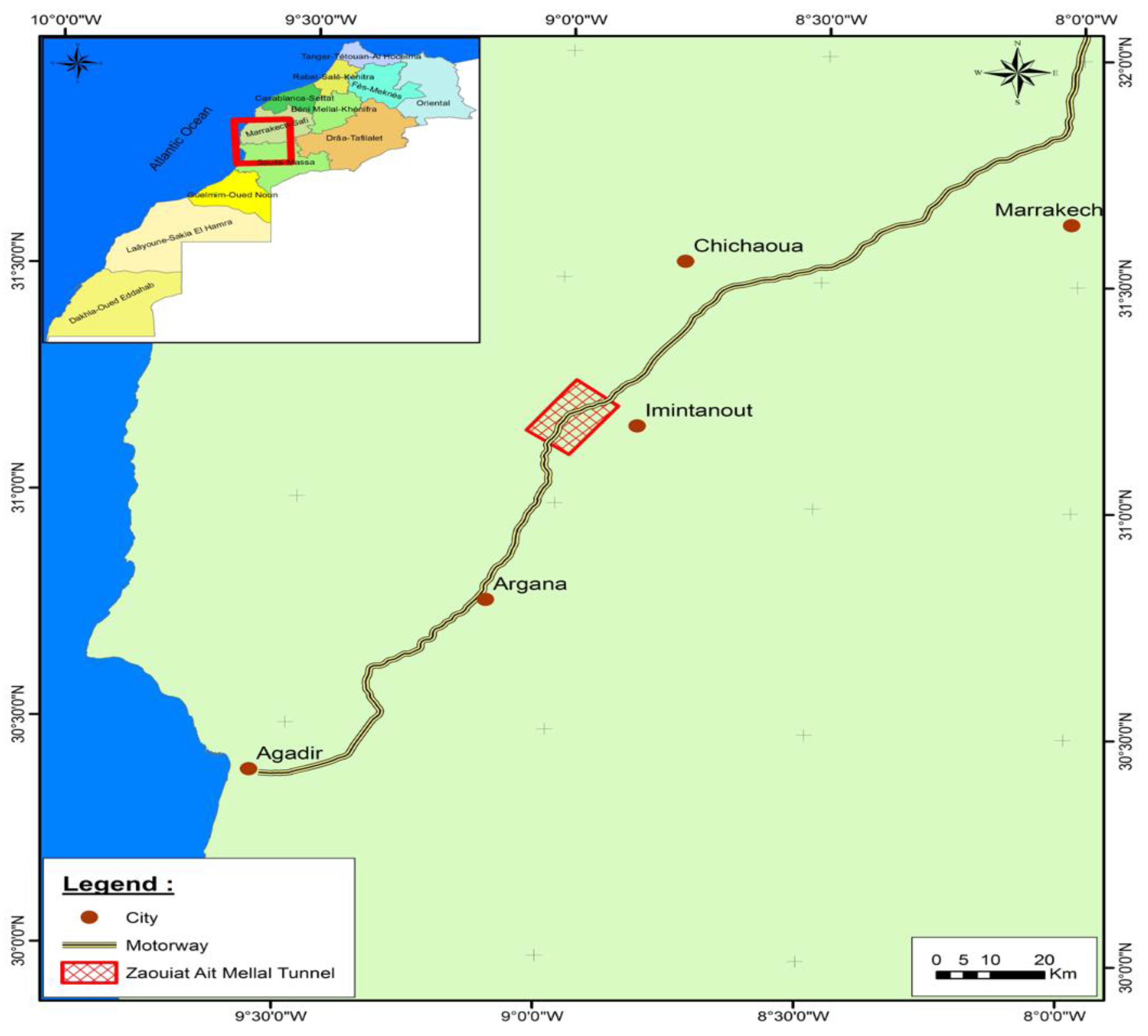
Zaouiat Ait Mellal tunnel is the first of the motorway twin tunnels in Morocco, located between Marrakesh and Agadir cities across the Atlas Mountains, between PK 8+300 and 8+850 (
Figure 1 and
Figure 2). This tunnel was built in 2010 with a length of 546 m and a distance between the tube centerlines of 26.5 m. The shape of the tunnel lining is a horseshoe, with 11 m width × 9 m height.
During and after the construction of the tunnels, rock instability became apparent on the ground opening, which immediately had to be adequately supported. Different investigations into the geological conditions were carried out to reveal the main characteristics of the rock mass surrounding the tunnel; these conditions can be changed along the tunnel, which requires flexible tunnel support methods [
16].
Different types of support can be used based on the design methods, which is the most empirical process, as reported in [
17,
18,
19,
20].
Rock bolts, steel ribs, and shotcrete are very common in underground construction.
Rock bolts:
The development of rock bolts started in the 1920s, and since that it has become the most common support method used in tunneling construction [
21]. The reason for this is that rock bolts are more flexible, more rational, and more economical for use within the zone of good and intermediate rock quality.
Steel ribs:
Steel rib supports are efficient and safe ground control elements in underground construction; they are embedded in shotcrete. Their application started in 1922 in the tunneling industry and they are frequently used if rock quality is weak.
The present project is conceived by the establishment of standard profiles that define the supports and tunnel lining for each soil cross-section in the face of the stress of the ground around tunnels. Thus, two types of support device are used along the twin tunnels for different cross-sections of soil, based on the analysis of rock quality, which are detailed in
Table 1.
2.2. Material Properties
The ZAM twin tunnels cross a rock formation from the Eocene and Cretaceous periods, which is predominantly limestone (
Figure 2). The distributions of materials are as follows:
Marls and marly limestone, massive brown limestone (type I);
Massive limestone locally vacuolar and siliceous (type II and III);
Limestone with fragmented nodules (type IV and V);
Partially fractured to fractured light brown limestone (type VI);
Marly limestone and grey-brown marls (type VII).
Table 2 and
Table 3 summarize the soil layers and the structural element properties based on geotechnical experiments according to their distributions, as mentioned in the longitudinal geotechnical profile (
Figure 2).
3. Numerical Modeling
3.1. Constitutive Numerical Models
The analysis is conducted using the 2D plane-strain numerical model, which was set up using FDM provided by Fast Lagrangian Analysis of Continua (FLAC) (FLAC 2005) [
14] software, with the following steps:
Step 1:
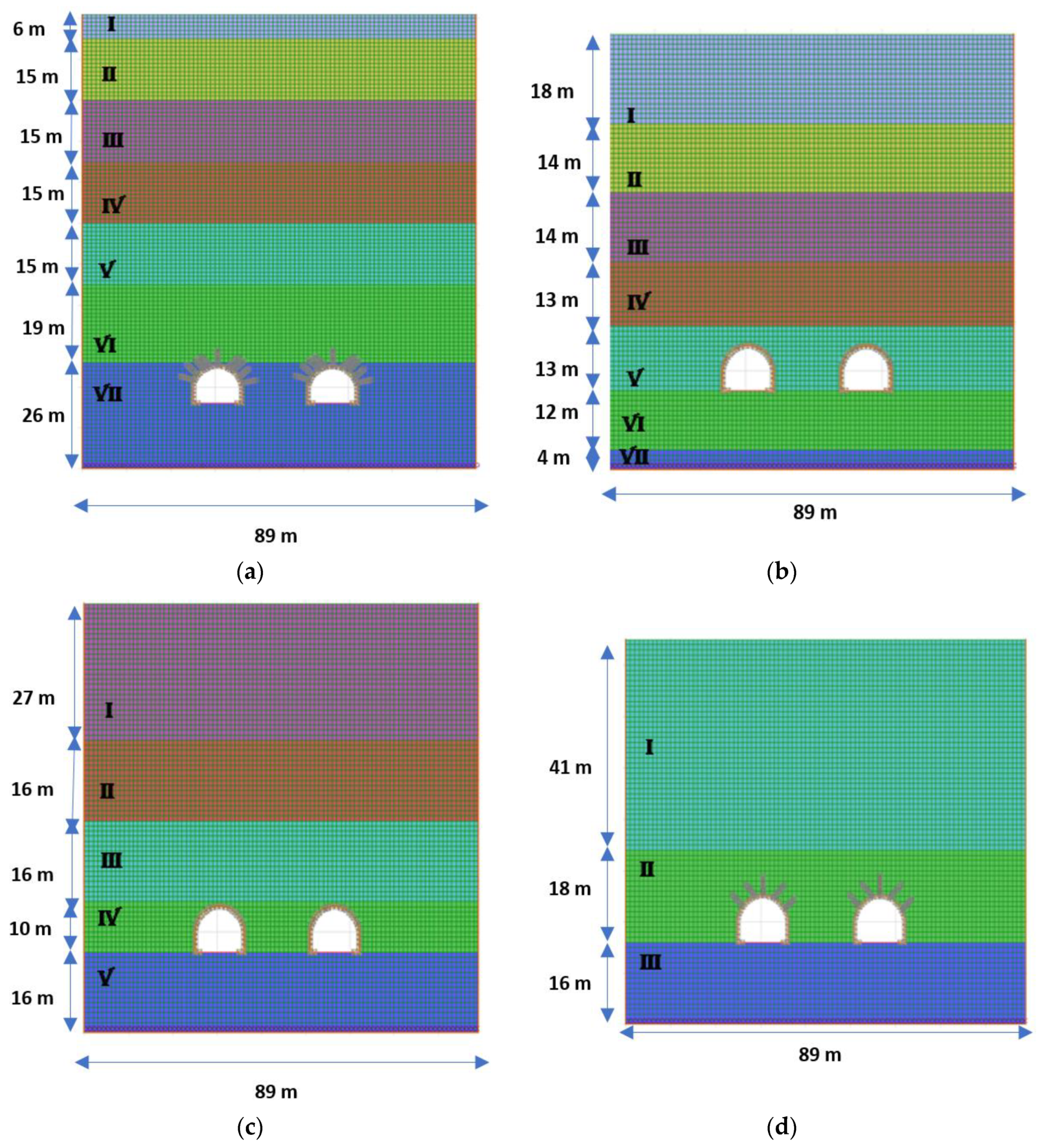
Using the FLAC 2D code, the models are created for the four cross-sections of chosen soil, as shown in
Figure 3a–d).
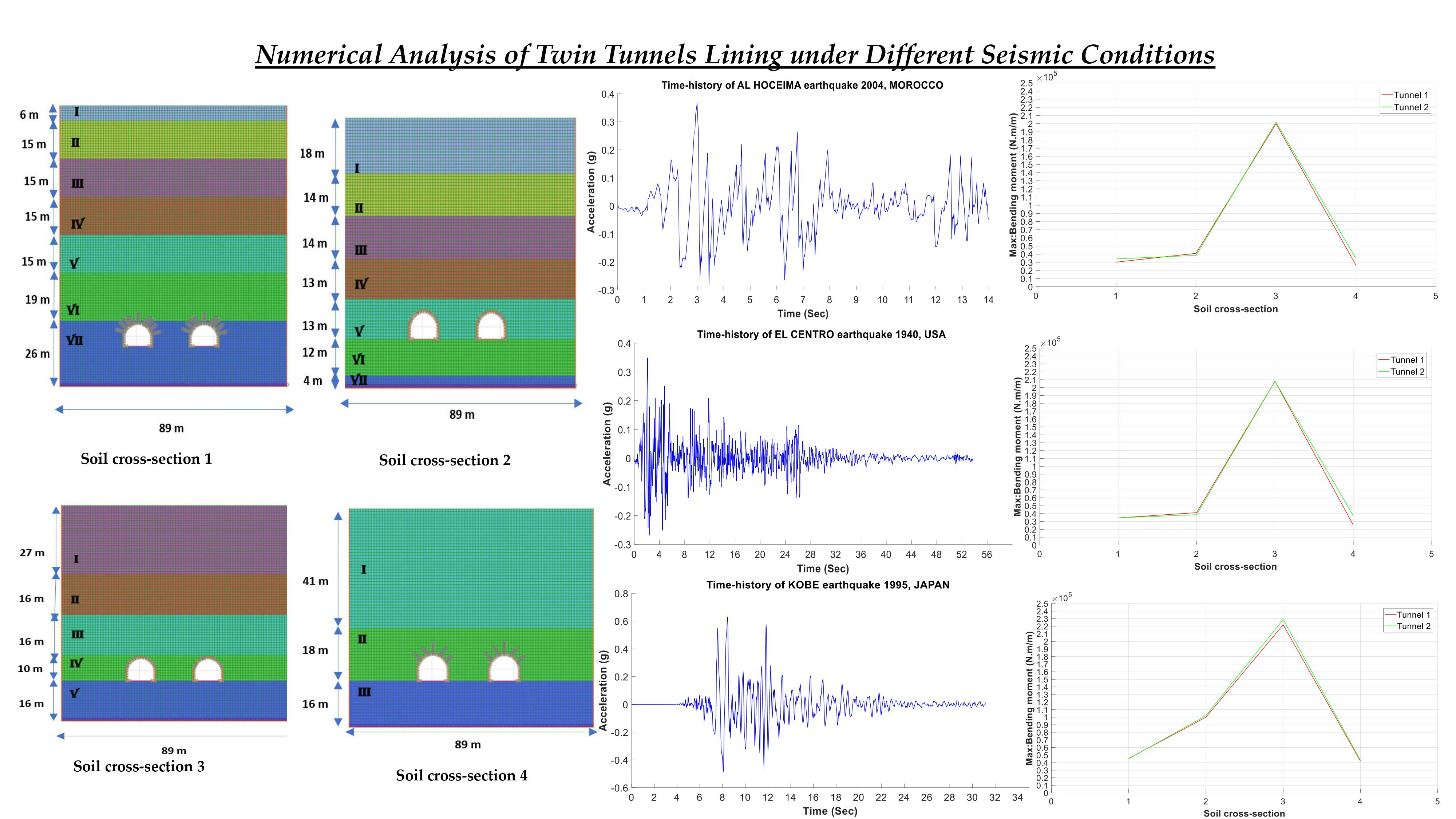
The grid model is chosen using different dimensions of soil layers along the twin tunnels: 89 m width × 111 m height for cross-section 1, 89 m width × 88 m height for cross-section 2, 89 m width × 85 m height for cross-section 3, and 89 m width × 75 m height for cross-section 4. The position of the twin tunnels is symmetrical.
The thickness of each layer of soil is determined from the geotechnical profile in
Figure 2. The size of the mesh in all the models is refined. The “beam” element is used for the tunnel lining and the model adopted for materials is a linear elastic–perfectly plastic, following the Mohr–Coulomb criterion.
Step 2:
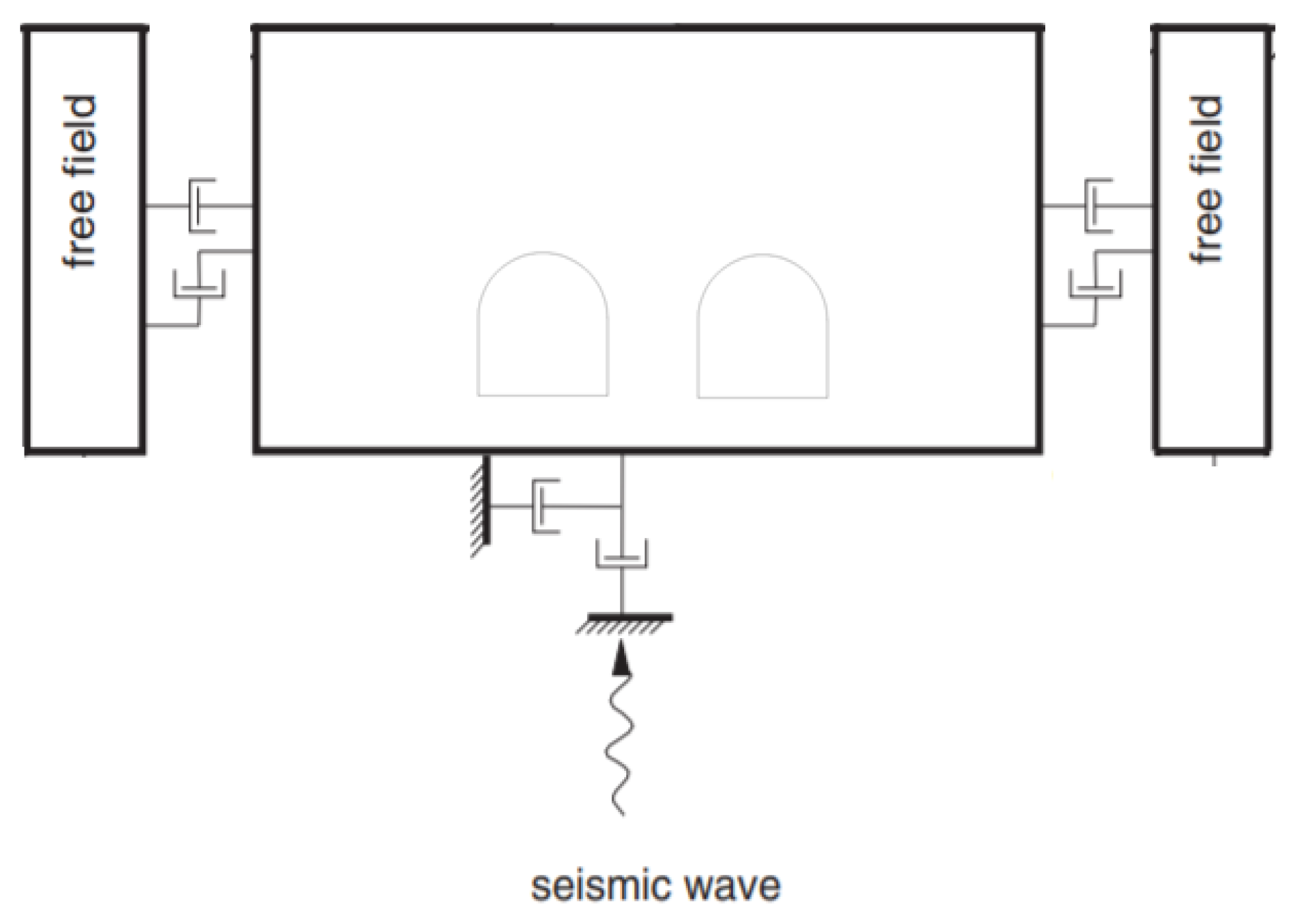
An absorbing boundary, called a free-field boundary, is applied to models with sufficient distance, in order to minimize the seismic wave’s reflection during the simulations, as shown in
Figure 4.
3.2. Dynamic Analysis
The dynamic analysis was performed using Rayleigh damping. The equation, expressed in matrix form, is as follows [
14]
C is a damping matrix with components proportional to the mass M and stiffness K matrices; α and β are the mass-proportional damping constant and the stiffness-proportional damping constant. The Rayleigh damping ratios of the soil and of the tunnel lining were fixed at 5% and 2%, respectively. [
14]
The dynamic input was applied to the base of the models, as shown in
Figure 4; the acceleration time history of three increasing earthquake magnitudes, 6.3, 6, 9 and 7, 2 in higher frequency content, are used and quoted as follows.
Al Hoceima 2004
Morocco experienced very violent earthquakes, with a magnitude greater than 6. The first one occurred in the city of Agadir south of Morocco in 1960, and the second one occured in Al Hoceima in 2004 in northern Morocco [
23,
24].
Since there are no recorded data on those events, we chose a safety accelerogram related to seismic history, which is used for various projects of civil engineering in Morocco, especially in Al Hoceima city (
Figure 5a), which has a peak ground acceleration PGA = 0.367 g of a duration of 14 s. (Source: LGCE EMI Rabat, Rabat, Morocco).
El Centro 1940
This earthquake occurred in California in the United States. It had a magnitude of 6.9. The accelerogram chosen in the numerical simulations had a peak ground acceleration PGA = 0.349 g with a duration of 45 s (
Figure 5b). (Source: Pacific Earthquake Research Center, Berkeley, CA, USA).
Kobe 1995
The 1995 earthquake affected the city of Kobe in Japan 1995, with a magnitude of 7.2. The chosen accelerogram (
Figure 5c) has a peak ground acceleration PGA = 0.6 g with a duration of 31 s. (Source: Pacific Earthquake Research Center, Berkeley, CA, USA).
4. Results and Discussion
The tunnel’s design requires a proper estimate of the structural displacements and internal bending moment in the linings. From the same perspective, the presented work is limited to a performance and safety analysis of the tunnel lining of ZAM twin tunnels.
4.1. Deformation of the Tunnel Lining
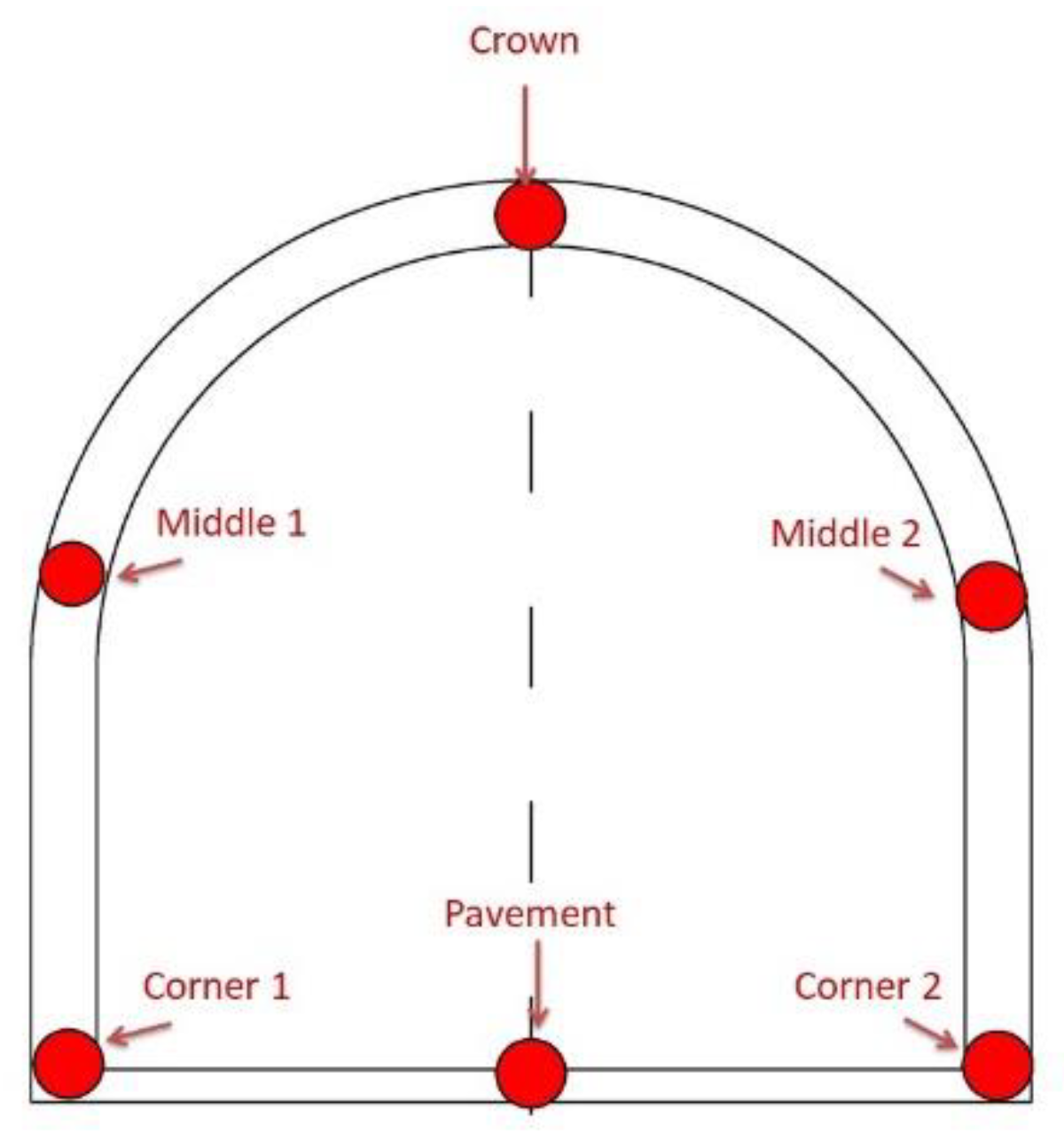
Due to the symmetry of the twin tunnels, one tunnel was chosen for the analysis. six points were selected, as shown in
Figure 6. These points are represented in the flowing location: Corner 1, Corner 2, Pavement, Middle 1, Middle 2, and Crown.
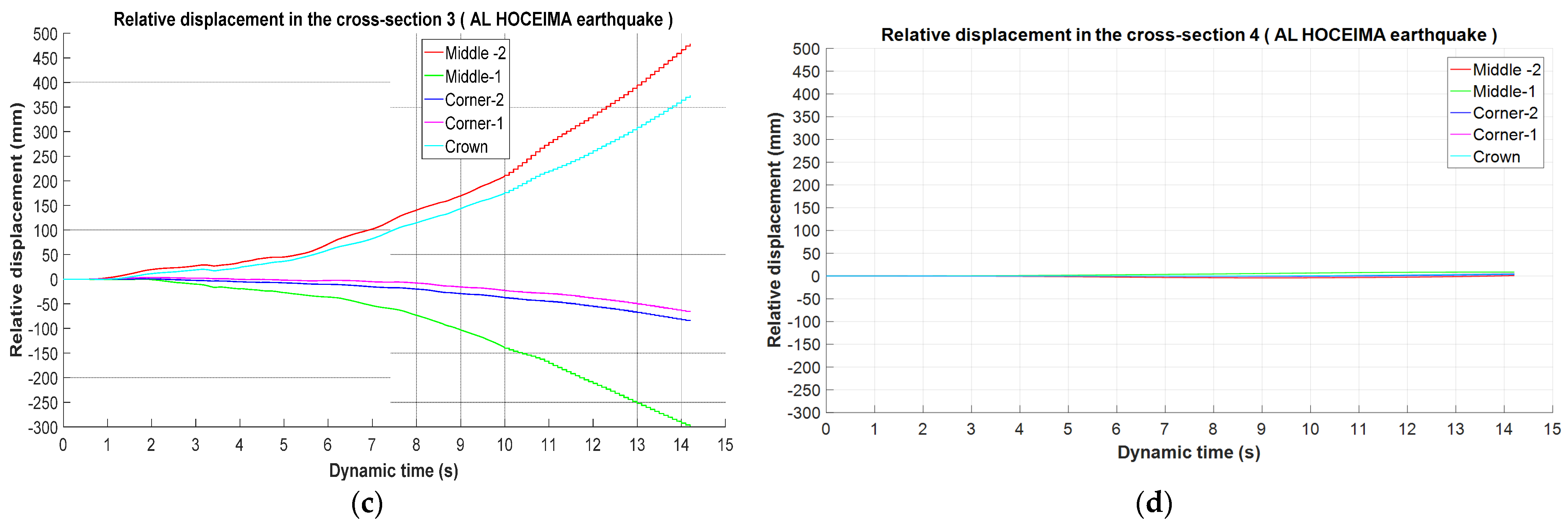
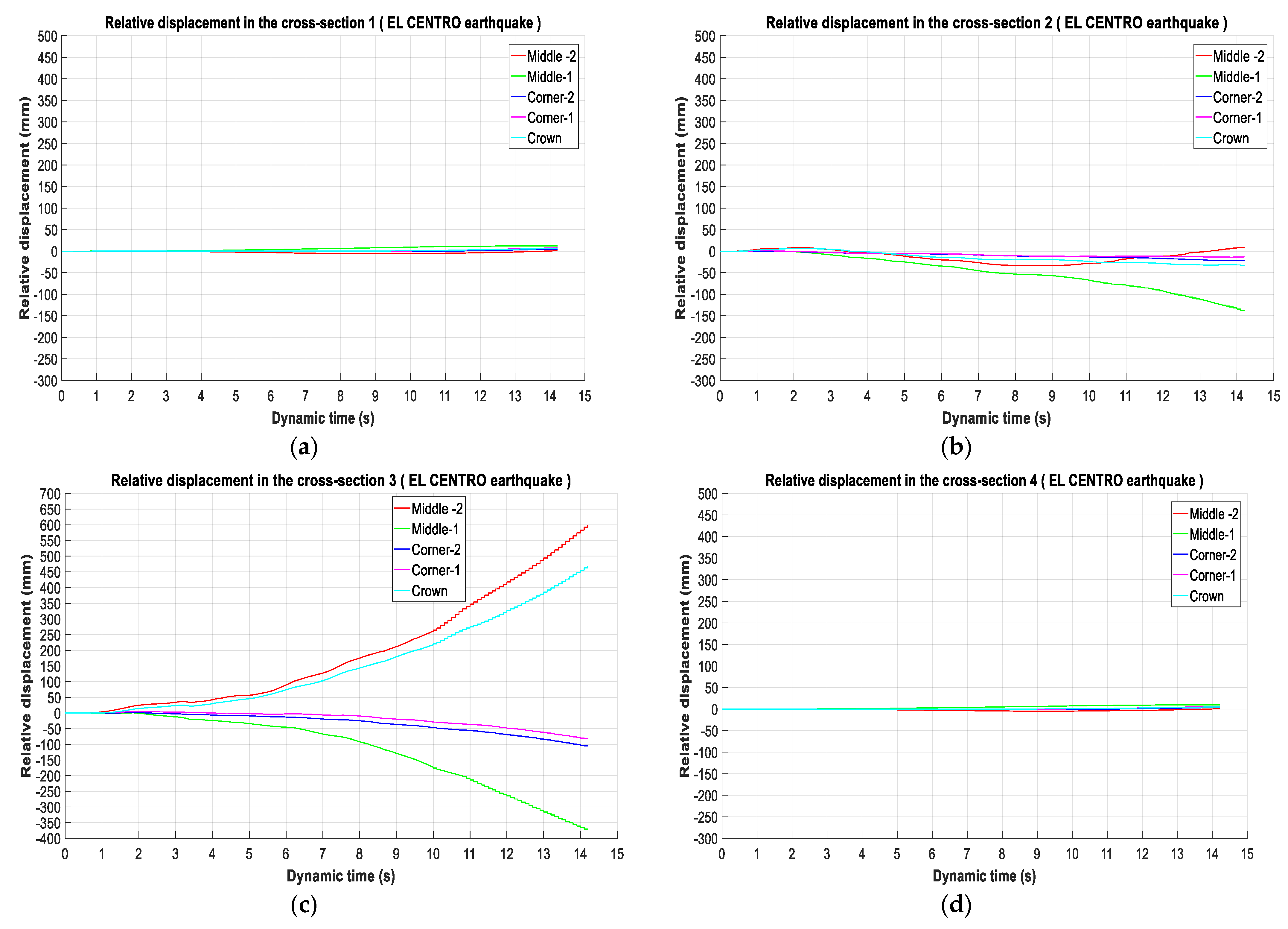
The results of the simulation have been measured under three seismic loadings during the dynamic time of 15 s. The calculation is presented in terms of relative displacement for different points on the tunnel lining in relation to the pavement point (reference point).
The analysis focused on the performance of the tunnel lining for the four cross-sections under three seismic scenarios, namely, Al Hoceima, el Centro and Kobe.
Figure 7,
Figure 8 and
Figure 9 display the distributions of the values for the different sections chosen along the tunnel. Regarding these sections, it is clear that variations between the different points on tunnel lining in sections 1 and 4 are quite similar for the three seismic scenarios in
Figure 7,
Figure 8 and
Figure 9a–d. Besides this, the points located in the middle are the most affected, with little difference between them up to 20 (mm).
Concerning sections 2 and 3, these variations are very remarkable for all points; it is interesting to note that there is a large difference in the middle points in the case of AL Hoceima, EL Centro, and Kobe: 110 (mm), 115 (mm), and 180 (mm) in section 2, and 770 (mm), 980 (mm) and 1020 (mm), respectively, in
Figure 7,
Figure 8 and
Figure 9b–c.
4.2. Safety of the Tunnel Lining
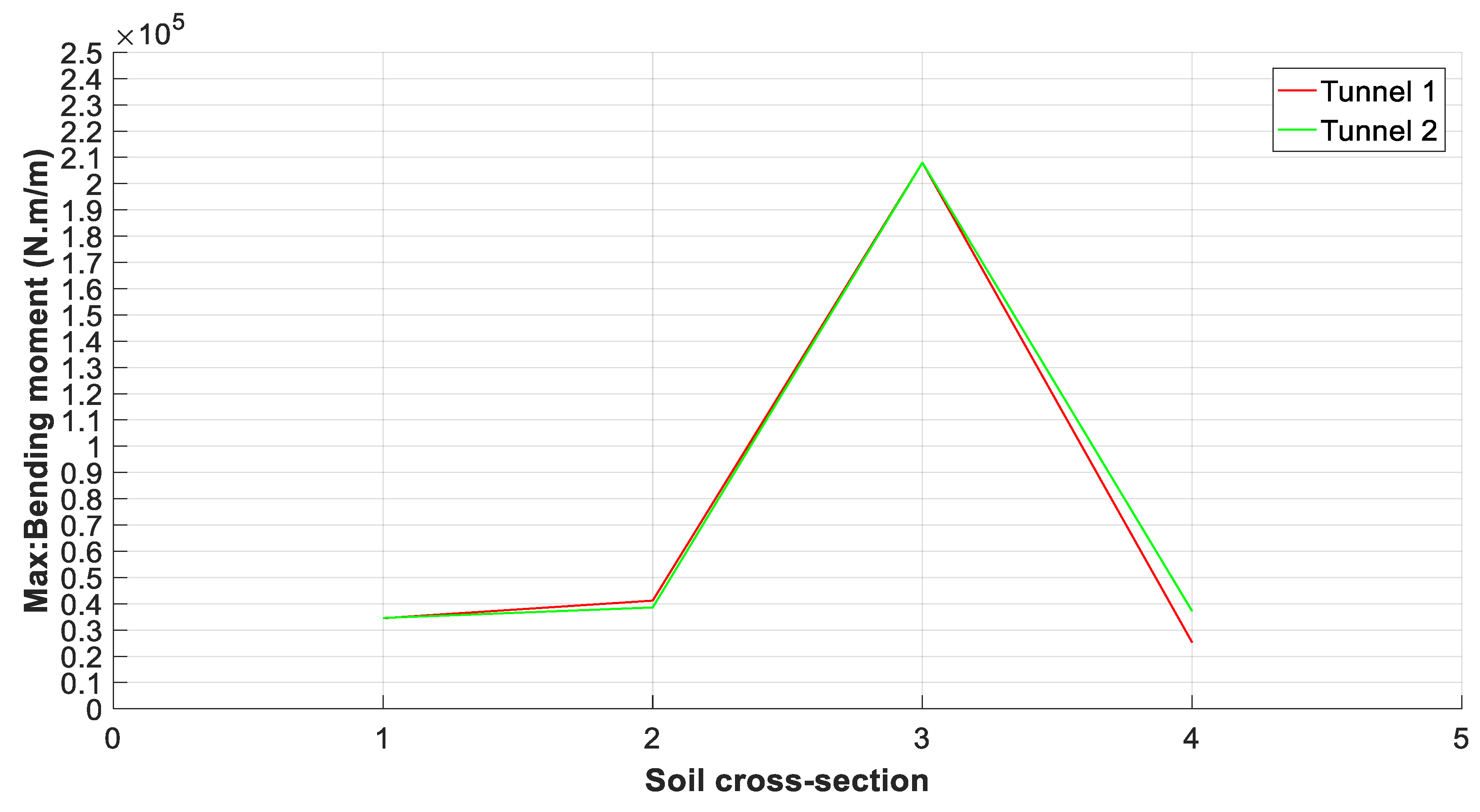
A plot of the maximum values of the bending moment on the liner of the twin tunnels for the different cross-sections is illustrated in
Figure 10,
Figure 11 and
Figure 12.
The bending moment is the main safety control factor of the lining along the twin tunnels. The distribution shows an increase in the cross-sections 2 and 3 compared to 1 and 4: 4.10 104 (N.m/m), 4.12 104 (N.m/m) in the cross-section 2 for Al Hoceima and El Centro earthquakes, respectively, and about 2.02 105 (N.m/m) and 2.08 105 (N.m/m) in cross-section 3. For the Kobe earthquake, we recorded 1.02 105 (N.m/m) in cross-section 2 and 2.29 105 (N.m/m) in 3.
4.3. Discussion
We begin with the analysis of the relative displacement variation values in the three seismic scenarios, which is taken as an indicator of the tunnel damage performance. It is observed that the tunnel lining located sections 2 and 3, which compared to sections 1 and 4, were the most affected. The development of cracks shown in these sections is due to the large relative displacement in located points at the middle of the tunnel lining, which allows for the generation of stress concentrations in the tunnel circumference.
Based on the type of tunnel support installed, it is clear that the seismic vulnerability increases in sections with steel ribs compared to Rock bolts for the three seismic scenarios. The sections with rock bolts support, namely 1 and 4, are more stable. The reason for this is that the support through which the tunnel passes has a very significant impact on its stability during an earthquake. The rock bolting also reduces stress concentration around the tunnel, especially if the rock bolts are used in high-stress areas [
25]. It is observed also that seismic damages to mountain tunnels are concentrated at zones of weak Rock, compared with another type of Rock [
26].
Even though steel rib supports are recommended when rock quality is weak, their behavior can generate a loss of performance in the tunnel lining under seismic conditions.
The support design for tunnels in weak rock is complex. It requires exploring all the options available to the weak rock, as the new methods (SEM-NATM), which try to optimize the design of the ground support, also reduce any excess capacity able to resist dynamic earthquake loading [
27].
The stability of the tunnel lining depends on ground deformability, especially in seismic loads. Indeed, for the safety factor of the “ZAM” twin tunnels, it is noted that the maximum values of the bending moment were also obtained in sections 2 and 3. These values can be taken as admissible during an earthquake.
5. Conclusions
In this work, three seismic scenarios were used to predict the performance of the tunnel lining along of ZAM twin tunnels, by the means of numerical simulations of the finite differences method provided by FLAC 2D software code. The models were built in four soil cross-sections with free field boundaries.
The results showed that the tunnel lining presented a higher seismic vulnerability in the steel ribs sections compared to rock bolt sections. This is illustrated by the large values of relative displacement, especially in the circumference of the tunnel lining.
The assessment of the bending moment for the different sections was the main control used to ensure the safety of the tunnel lining. The admissible values are also located in the sections with the steel ribs. These are required in poor rock conditions and their stiffness increases effectiveness ofthe lining during the earthquake.
Indeed, this study allows us to know the effect of different earthquakes on the tunnel lining according to the support used, which would be useful to help predict a better type of maintenance for seismic activity in the area.
Author Contributions
Investigation, A.E.O., E.M.E., and A.C.; Supervision, M.C., C.N.U., S.-E.C., M.R., F.H.C. and F.L.F. All authors have read and agreed to the published version of the manuscript.
Funding
This research received no external funding.
Acknowledgments
A large part of this research was done within the Continuum Mechanics and Structural Analysis Department, Carlos III University of Madrid, Spain, in the framework of Erasmus grant mobility of 6 months. The authors appreciate the grant from the Erasmus plus Program.
Conflicts of Interest
The authors have no conflict of interest to declare.
References
- Hashash, Y.M.A.; Hook, J.J.; Schmidt, B.; Yao, J.I. Seismic design and analysis of underground structures. Tunn. Undergr. Space Technol. 2001, 16, 247–293. [Google Scholar] [CrossRef]
- Iida, H.; Hiroto, T.; Yoshida, N.; Iwafuji, M. Damage to Daikai subway station. Special issue on geotechnical aspects of the January 17 1995 Hyogoken–Nanbu earthquake. Soils Found 1996, 36, 283–300. [Google Scholar] [CrossRef]
- Nakamura, S.; Yoshida, N.; Iwatate, T. Damage to Daikai subway station during the 1995 Hyogoken–Nambu earthquake and its investigation. Doboku Gakkai Ronbunshu J. Stage 1996, 6, 287–295. [Google Scholar]
- Ueng, T.S.; Lin, M.L.; Chen, M.H. Some geotechnical aspects of 1999 Chi-Chi, Taiwan earthquake. In Proceedings of the Fourth International Conference on Recent Advances in Geotechnical Earthquake Engineering and Soil Dynamics SPL-10. 1; University of Missouri—Rolla: Rolla, MO, USA, 2001; pp. 1–5. [Google Scholar]
- O’ Rourke, T.D.; Goh, S.H.; Menkiti, C.O.; Mair, R.J. Highway tunnel performance during the 1999 Düzce earthquake. In Proceedings of the 15th International Conference Onsoil Mechanics and Geotechnical Eengineering, Istanbul, Turkey, 27–31 August 2001. [Google Scholar]
- Yoshida, N. Damage to subway station during the 1995 Hyogoken-Nambu (Kobe) earthquake. In Earthquake Geotechnical Case Histories for Performance-Based Design; Kokusho, T., Ed.; CRC Press: Tokyo, Japan, 2009; pp. 373–389. [Google Scholar]
- Kontoe, S.; Zdravković, L.; Potts, D.; Menkiti, C. On the relative merits of simple and advanced constitutive models in dynamic analysis of tunnels. Géotechnique 2011, 61, 815–829. [Google Scholar] [CrossRef] [Green Version]
- Owen, G.N.; Seholl, R.E. Earthquake Engineering of Large Underground Structures; Rep. FHWA/RD-80/195, prep. for FHWA; URS/John A. Blume and Assoc.: San Francisco, CA, USA, 1981; p. 279. [Google Scholar]
- Chen, L.S.; Gui, G.M. Seismic performance of tunnel lining of side-by-side and vertically stacked twin-tunnels. J. Cent. South Univ. Technol. 2011, 18, 1226–1234. [Google Scholar] [CrossRef]
- Kampasa, G.; Knappett, J.A.; Brown, M.J.; Anastasopoulos, I.; Nikitas, N.; Fuentes, R. The effect of tunnel lining modelling approaches on the seismic response of sprayed concrete tunnels in coarse-grained soils. Soil Dyn. Earthq. Eng. 2019, 117, 122–137. [Google Scholar] [CrossRef]
- Anh Do, N.; Dias, D.; Oreste, P. 2d Seismic Numerical Analysis of Segmental Tunnel Lining Behaviour Bulletin of the New Zealnd Society for Earthquake Engineering. Bull. N. Z. Soc. Earthq. Eng. 2014, 47, 206–216. [Google Scholar]
- Hu, X.; Zhou, Z.; Chen, H.; Ren, Y. Seismic Fragility Analysis of Tunnels with Different Buried Depths in a Soft Soil. Sustainability 2020, 12, 892. [Google Scholar] [CrossRef] [Green Version]
- Zheng, Y.L.; Yang, L.D. Earthquake damages and countermeasures of underground structures. Earthq. Resist. Eng. 1999, 4, 23–28. (In Chinese) [Google Scholar]
- Itasca Consulting Group, Inc. FLAC—Fast Lagrangian Analysis of Continua, Ver. 5.0, User’s Manual. Minneapolis. 2005. Available online: https://www.itascacg.com/software/downloads/3dec-5-20-update (accessed on 29 December 2020).
- BoujemaouI, Y.; Hingant, P.; Laurent, J.G. The Zaouiat Aït Mellal tunnel The first Moroccan motorway tunnel, WORKSITES Tunnels Et Espace Souterrain-N°224-Mars/Avril 2011. Available online: http://aftes.asso.fr/publications_revue-tunnels.html?annee=201 (accessed on 29 December 2020).
- Palmstöm, A.; Nilsen, B. Engineering Geology and Rock Engineering; NBG: Oslo, Norwey, 2000. [Google Scholar]
- Barton, N.R.; Lien, J. Lunde Engineering Classification of Rock Masses for the Design of Tunnel Support Rock Mechanics. Rock Mech. 1974, 6, 189–236. [Google Scholar] [CrossRef]
- Bieniawski, Z.T. Geomechanics Classification of Rock Masses and Its Application in Tunneling Proc. Third Int. Congress on Rock Mechanics; ISRM: Denver, CO, USA, 1974; pp. 27–32. [Google Scholar]
- Bieniawski, Z.T. Engineering Rock Mass Classifications; John Wiley & Sons: New York, NY, USA, 1989; p. 251. [Google Scholar]
- Grimstad, E.; Barton, N. Updating of the q-system for NMT. In Proceedings of the International Symposium on sprayed Concrete, Fagernes, Norway, 22–26 October 1993; pp. 46–66. [Google Scholar]
- Luo, J. A New Rock Bolt Design Criterion and Knowlage-Based Expert System for Stratified roof. Ph.D. Thesis, Virginia Tech, Blacksburg, VA, USA, July 1999. [Google Scholar]
- Laboratoire Public d’Essais et d’Etudes, LPEE. Available online: www.lpee.ma (accessed on 29 December 2020).
- Medina, F.; Cherkaoui, T.-E. Geophysica, Precisions Sur Mécanisme du Foyer du Déisme d’Agadir (Maroc) du 29 Février 1960, Place Dans le Cadre du Sismotectonique du Maroc. Geophysica 1988, 24, 56–66. [Google Scholar]
- Medina, F.; El Alami, S.O. Focal mechanisms and state of stress in the Al Hoceima area (Central Rif, Morocco). Bull. de l’Institut Sci. 2006, 28, 19–30. [Google Scholar]
- Muya, M.; He, B.; Wang, J.; LI, G. Effects of Rock Bolting on Stress Distribution around Tunnel Using the Elastoplastic Model. J. China Univ. Geosci. 2006, 17, 337–354. [Google Scholar] [CrossRef]
- Zhang, X.; Jiang, Y.; Maegawa, K. Mountain tunnel under earthquake force: A review of possible causes of damages and restoration methods. J. Rock Mech. Geotech. Eng. 2020, 12, 414–426. [Google Scholar] [CrossRef]
- Jaramillo, C.A. Impact of seismic design on tunnels in rock—Case histories Underground Space (China). Underground Space 2017, 2, 106–114. [Google Scholar] [CrossRef]
| Publisher’s Note: MDPI stays neutral with regard to jurisdictional claims in published maps and institutional affiliations. |
© 2021 by the authors. Licensee MDPI, Basel, Switzerland. This article is an open access article distributed under the terms and conditions of the Creative Commons Attribution (CC BY) license (http://creativecommons.org/licenses/by/4.0/).


 ,
, 


