Article

Development of a Pultrusion Die for the Production of Thermoplastic Composite Filaments to Be Used in Additive Manufacture

by
Filipe Ferreira
1,2,*,
Pedro Fernandes
1,2,
Nuno Correia
2 and
António Torres Marques
1,2
1
FEUP—Faculty of Engineering of the University of Porto, 4200-465 Porto, Portugal
2
INEGI—Institute for Science and Innovation in Mechanical and Industrial Engineering, 4200-465 Porto, Portugal
*
Author to whom correspondence should be addressed.
J. Compos. Sci. 2021, 5(5), 120; https://0-doi-org.brum.beds.ac.uk/10.3390/jcs5050120
Submission received: 26 March 2021 / Revised: 16 April 2021 / Accepted: 28 April 2021 / Published: 1 May 2021
(This article belongs to the Special Issue Recent Advances in Composite Process Modeling and Characterization)

Abstract

:
The use of 3D printing has proven to have significant benefits to manufacture components with complex geometries with several types of materials and reinforcements for a wide variety of uses including structural applications. The focus of this study is to develop and implement a thermoplastic pultrusion process that can obtain a carbon fiber/polypropylene (CF/PP) filament for a 3D printing process. This development process included the design and finite element analysis of the die used to conform the filament, considering the adaptation of a filament-winding setup to achieve adequate production conditions. The finite element model tried to achieve homogeneous heating of the die with the use of a series of resistors controlled by PID controllers monitoring several thermocouples strategically positioned while the use of water circulating channels was responsible for the cooling effect. The die-heating environment is optimized for different scenarios with different initial temperatures, cooling temperatures, and pulling speeds. A series of experiments were performed under different conditions, such as different heating temperatures and pulling speeds to analyze the quality of the filament produced. The obtained filaments presented an average diameter of 1.94 mm, fiber volume fraction of 43.76%, and void content of 6.97%.

1. Introduction

Even though thermoset matrices dominated the market for continuous fiber reinforced composites for many years, thermoplastic matrices are revealing to be decent alternatives due to their better mechanical and ecological performances. Thermoplastic composites offer high damage tolerance, increased fracture toughness, short processing cycle times with excellent environmental stability. The main downside of using reinforced thermoplastic matrix composites is the requirement for better technologies due to their high viscosity compared to thermosets, which increases the complexity and difficulty of the consolidation and impregnation of reinforcements [1].
The use of thermoplastic matrices polymers has a wide variety of applications. Its use in 3D printing is presenting itself to be a good future investment due to the high mechanical properties obtained with these types of filaments. The main objective of this work is to develop a die capable of producing different high-quality filaments for 3D printing to be used according to their future use.

2. State of the Art

Additive Manufacturing (AM) is divided in seven different processing categories, where Laminated Object Modelling (LOM), Selective Laser Sintering (SLS) and Fused Filament Fabrication (FFF) are examples of. FFF was originally meant to be used solely for prototyping purposes, however its uses for end products can be seen in a wide variety of fields, such as electrical, biomedical, automotive and aerospace industry [2,3,4]. This process, also known as Fused Deposition Modelling, consists in extruding, layer by layer, a polymer filament through a heated nozzle, and it is one of the most widely used 3D printing techniques [5,6]. Polymers are the main 3D printing material because of their ease of production, low melting temperatures and availability. The 3D printing industry primarily uses polymers in various forms such as reactive, liquid solutions and thermoplastic melts [7,8].
Further material enhancements, and the possibility of including fiber reinforcements, offer an increasing perspective of future developments for AM. In fact, almost all of the existing AM applications could stand to benefit from fiber reinforcement. Considering both technology and material, it is possible to benefit from the geometric freedom and lightweight structure production techniques offered by this process while the mechanical performance is granted by the reinforcement [9]. Fiber reinforcement can greatly improve the properties of 3D printed parts with a polymer matrix. Fiber orientation and void content ( V c ) of composites are the main concerns in the 3D printing of these composites. Most of the commercially available 3D printing techniques would benefit from fiber reinforcement [10,11,12]. For example, as seen in Figure 1, reinforced polylactic acid (PLA) with CF presents a much higher tensile and flexural strength than PLA alone. Research has proven that reinforced polymers have higher mechanical properties than pure polymers. There are some issues to take into account though, such as the adhesion between the two components and their affinity, which may result in higher amounts of void content compromising the final result and application [10,13].
A wide variety of filament reinforcements exists, resulting from the combination of different types of fibers, such as carbon, glass, aramid, and natural fibers, arranged in different forms, such as short, long, and continuous fibers. Adding short fibers into a thermoplastic polymer grants superior mechanical properties to the filament and they are easy to manufacture. Usually they are produced by injection, extrusion compounding, or compression molding process [15]. Although they improve stiffness and strength of neat thermoplastics, this improvement is limited due to the presence of porosity in printed parts, resulting in poor load transfer between fibers [12]. Continuous fiber reinforcement transfers and retains primary loads within unbroken strands of fiber. This results in lower load transfer through the polymer and it allows for higher demanding applications in comparison to short fiber reinforcement [11].
Despite the promising value of fiber reinforcement, this application has several issues which have yet to be addressed and resolved. These issues include the formation of agglomerates, heterogeneous composites, blockage of printer heads, non-adhesion and the increase of the curing time [16].
In-situ fusion and ex-situ prepreg are the two main categories of continuous fiber printing described in the literature [17,18]. The in-situ systems utilize two input materials, typically a dry fiber feed-stock (the reinforcing fiber) and a neat polymer (the matrix polymer), which are combined during the printing process. One of the most widely used techniques is known as “in-nozzle impregnation” [19]. In this process, the dry fiber is typically pre-threaded through the printer nozzle before printing, and the fiber is also preheated using a coil heater or IR lamps. The polymer is fed by a motor-driven hobbed gear into the melt zone of the hot-end, and the preheated fiber and melted polymer converge in this melt zone where they are pushed together by the feeding polymer filament. The ex-situ prepreg system, in opposition to the in-situ system, manufactures the composite filament in separate from the printing machine. These filaments are pre-impregnated filaments, manufactured by a separate extrusion process. The prepreg is then spooled and transferred to the printing system for deposition. The process of printing using this method is simpler and allows for superior fiber impregnation during the manufacture stage, since the dedicated extrusion process enables for more pressure and better impregnation on the resulting filament when comparing to the in-situ system [12]. Dickson et al. [12] compared the work of several authors, and concluded that while the addition of short fibers to printing filaments improves stiffness and strength, continuous fibers produce materials with properties which are orders of magnitude higher than what is possible otherwise. However, Dickson et al. point out that making these continuous fiber filaments in-situ leads to high porosity which ultimately degrades the properties of the filaments and of the components. Finally this work highlights that ex-situ prepregs provide superior quality parts with excellent polymer infusion at the cost of a necessarily more complex manufacturing processes. This is ultimately the goal of the research presented in this paper: to assess the producion of high quality continuous filaments obtained through ex-situ processes and to study the conditions which produce better mechanical properties while taking into consideration the whole manufacturing line and its inherent complexity.
There are several ways to prepare a composite filament. These include powder-prepregs, melt/dissolver prepreg, coated roving, commingling/hybrid yarn, and tape. Usually, these filaments are produced by plastic extrusion machines called filament extruders. These machines mix raw plastic granules and additives, if any, and then they are transported through a feed hopper to the heater nozzle with the help of a screw shaft as seen in Figure 2. The raw material is melted in the filament extruder and removed in the desired diameter (usually 1.75 mm or 3 mm) and turned into a film stip with several colors and properties [20,21].
Among different possible manufacturing processes such as extrusion, pultrusion, filament winding among others, pultrusion is the most directly relevant process for the consolidation of a commingled yarn into an AM filament. Pultrusion, in this context, is used to produce a consolidated AM filament with a constant cross-section by pulling impregnated reinforced material through a heated forming die. In this process, unidirectional prepreg tows or tapes are guided through a pre-heater, which raises their temperature close to the melting point of the polymer. Then, the heated polymer and fibers enter a series of dies which consolidate, form, and cool the material. A significant taper is commonly used in the entrance die to help consolidate the polymer with fibers [23].
Within this process, there are mainly two types of materials that can be used: thermosets and thermoplastics. The latter is revealing to be a better option, not only ecologically but also when compared with the most common thermosets, as they present higher values of toughness, hence better behavior to impact and damage. The difficulties in replacing thermoset by thermoplastic matrices in the polymeric composites result from the nature of their type of matrix. It is necessary that the matrix is in a viscous liquid state to ensure a decent fiber wetting, which represents a problem for the thermoplastic resins, which presents, in the molten state, viscosity in the range of 50–2000 Pa.s, while the thermosetting resins do not exceed the 50 Pa.s at the beginning of the cure reaction [24]. Despite these problems, it was verified that the damage tolerance requirements imposed on advanced applications could only be fulfilled when using thermoplastic matrices [25]. The better mechanical properties led to the attempts to develop new methods of production and processing based on thermoplastic matrices to redouble in the end of the 20th century. Consequently, more appropriate methods of production of pre-impregnated materials with thermoplastic matrix have emerged and new knowledge has been acquired to optimize these methods [24].
In this work, continuous fiber commingled yarns are explored as a basis for the production of AM filaments. Despite the technological challenges with the impregnation and wetting of the fibers, which impacts the quality of the consolidation and mechanical properties of the produced commingled plastic composite [26,27,28]. Hence, this paper explores the possibilities introduced by commingled yarns in terms of improved dispersion of polymer matrix within the fiber bundle as well as with better interface properties obtained through this method [27,28,29,30].

3. Materials and Methods

3.1. Materials Used

The experiments detailed in this manuscript were performed using continuous fibers. This choice allows the possibility of achieving improved strength and stiffness properties when compared to analogous discontinuous fiber composites, as they suffer from the existence of stress concentration points in the fiber discontinuities [13,31]. The produced reinforced filaments are meant to be used in a FFF process.
In this experiment, a combination of sized CF (Tenax-E HTS 45 P12 12K 800 TEX) and PP (Chemosvit Prolen 2700 dTEX-264) is used. This specific carbon fiber sizing is denominated by the manufacturer as P-sizing. P-sizing is a thermoplastic sizing which is compatible to several thermoplastics especially to high-end thermoplastics as well as to medium performance thermoplastics. The main benefit of this preparation is its high temperature resistance up to 400 °C combined with good processing behaviour. Compared to unsized carbon fibers the processing of this CF is superior due to less fiber breakages. The properties for these materials are presented in Table 1. Carbon and polypropylene are known to have some affinity issues and the success of the filament production is a positive sign for the validation of the process used.

3.2. Experimental Process

Once both fibers are commingled the conversion process takes place in four steps. The first is the use of CF and PP from pre-made commingled rovings in a rotating creel. The second is the pre-heating of the previously entangled yarn using a pre-heating oven before entering the die. The third step aims to heat the PP in the die above its melting temperature, allowing it to mix with the fibers with the possibility of cooling by using water, or simply cooling in the air. The fourth and last step is the winding in the winding machine, which provides the pulling speed and force necessary for the continuity of the process. An illustration of the process can be seen in Figure 3.
Pultrusion experiments were conducted using different pulling speeds and heating temperatures. The objective was the determination of the most suitable process parameters that allow fiber volume fraction to reach 40%, lower void content, and continuity of the process. Two direct methods were used to examine impregnation, the measuring of volume fraction of voids and qualitative evaluation of microscopic photographs.
The commingling machine, the pre-heater and the winding machine used in the experiments can be seen in Figure 4.

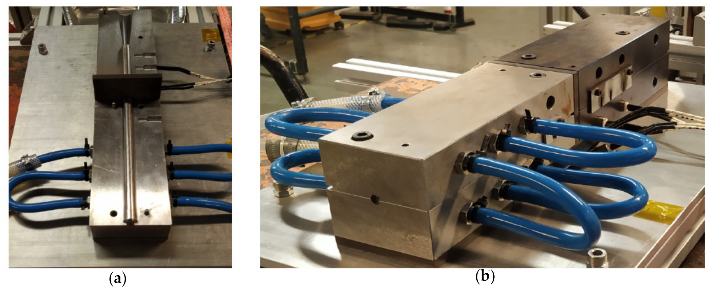
3.3. Development of the Die

The experimental setup die was based on the work by Andreas Carlsson and B. Tomas Astrom [32], with modifications in filament geometry. As these materials are being produced for AM, the original 3 × 30 mm cross-section was adapted to a circular section with 2.2 mm diameter. The angle of the tapered region was also changed to 4 to promote the build-up of consolidating pressure [33]. The main dimensions of the die are presented in Figure 5.
Furthermore, two VETROTHERM® insulator panels were added, between the heating and cooling die and between the die and the bottom plate, further improving the temperature control on both parts of the die. A further adaptation was the inclusion of an internal and removable inner-die enables the production of different filaments (as this inner-die can be swapped to enable different geometries/diameters). Notably this swappable inner-die also enables different material combinations for a large array of applications. This addition also helps to stabilize the heat flow from the heating to the cooling zone of the die and can be seen in Figure 6. The die was designed to heat the filament until it reaches the melting point, then cooling it for consolidation while this filament is being pulled at a constant speed. For the heating zone, several resistors monitored by PID controllers via thermocouples are used to heat the die, and subsequently the filament. The heating zone is separated from the cooling zone with the use of an insulator, preventing an inefficient heat transfer between the two parts of the die. The designed die was manufactured on Steel AISI/SAE 1045 and the cavities have low surface roughness and it can be seen in Figure 6. The alignment is ensured by assembling all the pieces in a machined plate.

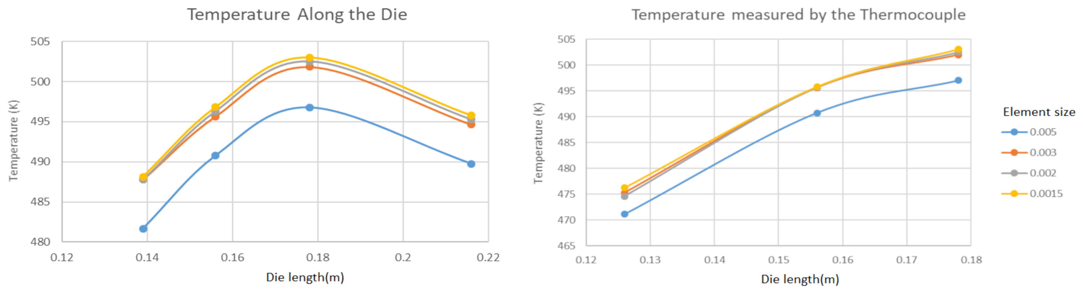
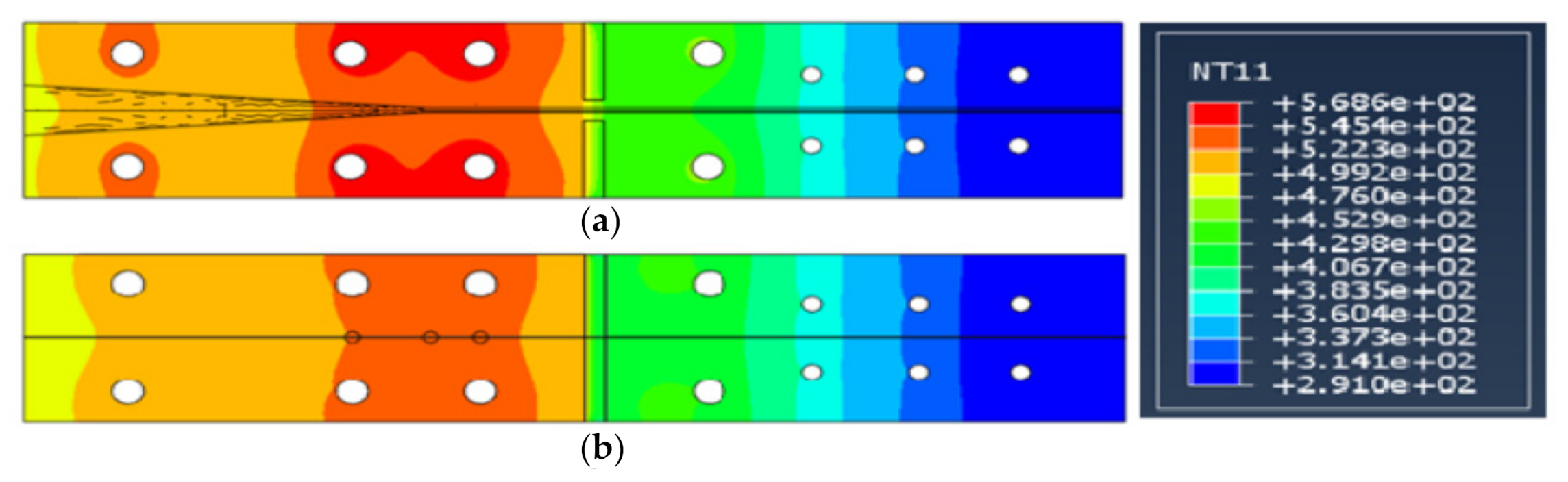
4. Numerical Simulation

Abaqus Simulation

The finite element models used in this research were implemented in ABAQUS®, using an explicit approach and a linear geometry. Due to the symmetrical geometry, only one-fourth of the die was modeled, using 8-node linear heat transfer brick elements.
The boundary conditions applied accounted for the existence of both conduction and convection phenomena in the numerical model. To estimate the time needed to heat the die to a suitable temperature, the heat transfer process was simulated as transient response.
The geometry proposed is based upon the work of Linganiso [34]. The design process aimed at ensuring a constant temperature along the contact zone with the pulled yarn. A series of numerical tests were performed, determining the most suitable position for a set of resistors and thermocouples. The resistors considered had a diameter of 12.5 mm, a length of 60.0 mm, and a maximum power output of 170,000 W/m 2 . However, a safety factor of 10% was used, reducing the maximum output to 150,000 W/m 2 .
The element size used in the finite element model was optimized, aiming at improving the accuracy of the model with a minimal computational cost. To do so, the temperature profile obtained by the finite element model when using element sizes of 0.005, 0.003, 0.002, and 0.0015 mm were compared. As shown in Figure 7, reducing the element size beyond 0.03 does not lead to significant changes in the value of temperature determined. Therefore, an element size of 0.03 was chosen for the finite element analysis used in this research.
This simulation used all of the resistors, but only the rightmost water channel at 288 K (15 °C), providing a more suitable temperature gradient for the cooling of the filament. The die considered additional water channels. Although they were not necessary for the current application, they were included to allow a more precise temperature control when using the mold with different material combinations.
The temperature in the heating zone was always kept above the melting temperature of the PP, not allowing PP to consolidate in the entrance area so it did not compromise the continuity of the process. In the cooling area, this was also done so as to not induce a fast drop of temperature, which might have lead to a non-desirable frictional force along with the cooling die. ABAQUS® results are presented in Figure 8.

5. Results

5.1. Experimental Plan Using the Taguchi Method

The creel introduced separate rovings of commingled CF and PP. The amount of these components varied throughout the experimental plan to enable more testing parameters. Samples were taken and later observed through optical microscopy and burning test in order to determine the fiber volume fraction (as the goal was 40% of fiber volume fraction).
To determine the fiber volume fraction and the void content, the ASTM D3171 (Procedure G—Matrix burnoff in a muffle furnace) standard was followed, which consists of the following procedure [35]:
  • Preconditioning was performed according to ASTM D792. 15 samples weighting around 1 g were conditioned for approximately 48 h at 23 °C with 50% Relative humidity.
  • With the samples ready, the ASTM D 3171 procedure was ready to be performed. The samples were placed in a muffle, being incinerated at 425 °C for 6 h ensuring that the carbon fiber is not degraded.
  • Using the density of the CF and PP and their respective masses, it is possible to determine the percentages present in the initial sample. For simplicity in the analysis, the values obtained by these procedures will be averaged and the conclusions will use these values as reference.
A Taguchi based design-of-experiments (DOE) was used to determine the minimum number of tests necessary to estimate the correlations between the input variables (e.g., pulling speed etc.) and process outputs (e.g., porosity etc.). Determining these correlations experimentally, enables the understanding of the windows for optimization of input parameters of the complex ex-situ manufacturing process [36,37]. This method was applied by using a dedicated DOE software (Design Expert 12®). By inserting the inputs (available number of CF and PP rovings, heating temperature, and pulling speed), the number of experiments possible, and outputs (fiber volume fraction and void content) the software returned a plan for several inputs according to the physical limitations imposed by the process to later optimize the value of fiber volume fraction and minimize the void content. It was set that the number of CF and PP rovings would be either two or three and from six to nine, respectively, the heating temperature would be between 220 °C and 260 °C and the rolling speed would be either 6.9 or 13.7 (mm/s) which were the two lowest available speeds provided by the winding machine. After experimentation with the inputs given by the software, it analyzes the inputs with the experimental outputs and predicts the best possible experiment to achieve the pretended fiber volume fraction and minimal void content based on the results associated with the inputs. The plan returned the experiments presented in Table 2:

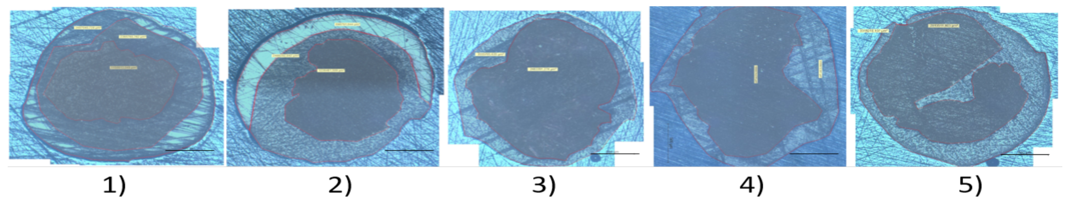
5.2. Experimental Results and Discussion

From these experimental results it becomes possible to measure the influence in the resulting filament by increasing the amount of PP and CF in the yarn, the rise of temperature in the die, and the difference between two different pulling speeds. The rating of the filament is performed by evaluating the fiber volume fraction and void content followed by some microscopic images of the cross-section of the samples as seen in Figure 9.
Comparing the pictures taken becomes clear that samples number 4 and 5 are the most consistent, in terms of the aspect of two distinct zones, being zone 1, the zone where PP and CF are mixed and zone 2, the zone where the excess of unmixed PP is present. Samples number 1 and 2 have a third zone, in the outer section of the filament, and whose most probable origin is the mixing of the resin used for sampling and the PP due to lower ratios of CF/PP. These three zones can be seen in Figure 10.
Sample number 3 presents broken fibers in the inner zone as can be seen in Figure 11.
Zoomed pictures were taken from sample number 5 in order to see details otherwise not perceptible. Pictures with zoom of ×75, ×150, ×300 and ×750 were taken and are presented in Figure 12. At 300× and 750×, the fibers become more perceptible and distinguishable from the PP matrix (lighter dots in the matrix).
Three samples of each were taken and analyzed. The results of the experiments are summarized in Table 3.
A close inspection of the results in Table 3, allow some preliminary analysis: Between samples 1 and 2, the increase of PP, pulling speed, and temperature lead to a void reduction on sample 2, for the same fiber volume fraction and an increase of the cross-section. Naturally one can expect that the constant fiber volume fraction remains constant as the CF on both samples is the same.
Comparing samples 1 and 3, increasing one more roving of CF and the pulling speed in sample 3 leads to a higher fiber volume fraction and cross-section area, as is to be expected, but at a higher void content, possibly because, with higher CF rovings, the amount of PP was not enough to impregnate the extra fiber that was added.
Comparing samples 1 and 4, one can observe that increasing the amount of CF in the rovings used while also increasing the heating temperature in sample number 4, led to higher fiber volume fractions in sample 4, as is to be expected, while also increasing the void content to the highest value in this experiment.
Comparing samples 4 and 5, one observes that increasing the pulling speed influences the void content while also affecting the cross-sectional area: higher pulling speed, decreases the void content and increases the cross-sectional area of the filament.
Comparing samples 3 and 5, the increase in heating temperature in sample number 5, produced a slight reduction in void content, fiber volume fraction as well as a decreasing the cross-sectional area.
One example of the resulting filament and its winding process is presented in Figure 13.

6. Conclusions

In this work, a die was designed to pultrude rovings carbon fibers and polypropylene to create a filament for additive manufacturing (a 3D printing material).
This research used simulation to predict the heating and cooling process of the die during pultrusion. This led to a deeper understanding of the die performance, and suggested the use of four sets of resistors, regulated via PID controllers and thermocouples in the heating zones, as well as a cooling zone with separate water channels for different cooling temperatures and controlled temperature gradient.
Results show fiber volume fractions varying from a minimum of 38.55 % to a maximum 48.06 % , void content from 3.43 % to 9.79 % , and approximate diameters from 1.73 mm up to 2.12 mm.
In summary it was possible to observe that fiber volume fraction can be controlled and follows the well established governing equations for this process. Also, it can be concluded from experimental observations that higher quantities of polypropylene lead to a more consistent filament, and also that the cooling zone was unnecessary for the combination of materials in question. Notably, it was observed that without the twist and entanglement of the tows, the thermoplastic filaments tend to melt at the entrance of the die. Finally, it is important to note that experiments allowed us to observe that the increase of pulling speed and temperature lowers void content.
This experiment allows the production of several combinations of reinforced thermoplastic filaments used for additive manufacture with various diameters. The enhancement of mechanical properties granted by the reinforcement fibers enables higher demanding applications for these types of materials.
It is recognized that the fiber-matrix pair should be reassessed (as carbon fibers do not show significant affinity with polypropylene). However, for the experimental purposes of this paper, this combination allowed the testing of adhesion and void formation, with a lower wetting condition which enables a better understanding of the required die design and of the relevant processing parameters.
This fact can compromise some of the results obtained by this process. It was posited that The use of carbon fiber or glass fiber with different types of thermoplastics can improve the quality of the filament which is produced. SEM pictures can be a good improvement to work, as well as tensile tests for 3D printed specimens.

Author Contributions

Conceptualization, F.F., P.F., N.C. and A.T.M.; Data curation, F.F., P.F., N.C. and A.T.M.; Formal analysis, F.F., P.F., N.C. and A.T.M.; Funding acquisition, N.C. and A.T.M.; Investigation, F.F., P.F., N.C. and A.T.M.; Methodology, F.F., P.F., N.C. and A.T.M.; Project administration, N.C. and A.T.M.; Resources, N.C. and A.T.M.; Supervision, P.F., N.C. and A.T.M.; Validation, F.F., P.F., N.C. and A.T.M.; Visualization, F.F.; Writing—original draft, F.F.; Writing—review & editing, F.F., P.F., N.C. and A.T.M. All authors have read and agreed to the published version of the manuscript.

Funding

Authors gratefully acknowledge the funding of Project NewSat—“Development of a compact integrated sensor and satellite for earth observation” n° 45918, financed by Programa Operacional Regional do Norte, through “Fundo Europeu de Desenvolvimento Regional (FEDER)”.

Institutional Review Board Statement

Not applicable.

Informed Consent Statement

Not applicable.

Data Availability Statement

Not applicable.

Conflicts of Interest

The authors declare no conflict of interest.

Abbreviations

The following abbreviations are used in this manuscript:
3DThree Dimension
AMAdditive Manufacture
CFCarbon Fiber
PIDProportional Integral Derivative
PLAPolyactic Acid
PPPolypropylene
V f Fiber Volume Fraction

References

  1. Novo, P.; Silva, J.F.; Nunes, J.; Marques, A. Pultrusion of fibre reinforced thermoplastic pre-impregnated materials. Compos. Part B Eng. 2016, 89, 328–339. [Google Scholar] [CrossRef] [Green Version]
  2. Li, J.; Monaghan, T.; Nguyen, T.; Kay, R.; Friel, R.; Harris, R. Multifunctional metal matrix composites with embedded printed electrical materials fabricated by ultrasonic additive manufacturing. Compos. Part B Eng. 2017, 113, 342–354. [Google Scholar] [CrossRef] [Green Version]
  3. Norman, J.; Madurawe, R.D.; Moore, C.M.; Khan, M.A.; Khairuzzaman, A. A new chapter in pharmaceutical manufacturing: 3D-printed drug products. Adv. Drug Deliv. Rev. 2017, 108, 39–50. [Google Scholar] [CrossRef]
  4. Liu, R.; Wang, Z.; Sparks, T.; Liou, F.; Newkirk, J. Aerospace applications of laser additive manufacturing. In Laser Additive Manufacturing; Elsevier: Amsterdam, The Netherlands, 2017; pp. 351–371. [Google Scholar]
  5. Wang, J.; Xie, H.; Weng, Z.; Senthil, T.; Wu, L. A novel approach to improve mechanical properties of parts fabricated by fused deposition modeling. Mater. Des. 2016, 105, 152–159. [Google Scholar] [CrossRef]
  6. Alafaghani, A.; Qattawi, A.; Alrawi, B.; Guzman, A. Experimental optimization of fused deposition modelling processing parameters: A design-for-manufacturing approach. Procedia Manuf. 2017, 10, 791–803. [Google Scholar] [CrossRef]
  7. Gu, D.D.; Meiners, W.; Wissenbach, K.; Poprawe, R. Laser additive manufacturing of metallic components: Materials, processes and mechanisms. Int. Mater. Rev. 2012, 57, 133–164. [Google Scholar] [CrossRef]
  8. Hofmann, M. 3D printing gets a boost and opportunities with polymer materials. Acs Macro Lett. 2014, 3, 382–386. [Google Scholar] [CrossRef]
  9. Ferreira, I.; Machado, M.; Alves, F.; Marques, A.T. A review on fibre reinforced composite printing via FFF. Rapid Prototyp. J. 2019, 25, 972–988. [Google Scholar] [CrossRef]
  10. Parandoush, P.; Lin, D. A review on additive manufacturing of polymer-fiber composites. Compos. Struct. 2017, 182, 36–53. [Google Scholar] [CrossRef]
  11. Sugiyama, K.; Matsuzaki, R.; Malakhov, A.V.; Polilov, A.N.; Ueda, M.; Todoroki, A.; Hirano, Y. 3D printing of optimized composites with variable fiber volume fraction and stiffness using continuous fiber. Compos. Sci. Technol. 2020, 186, 107905. [Google Scholar] [CrossRef]
  12. Dickson, A.N.; Abourayana, H.M.; Dowling, D.P. 3D Printing of Fibre-Reinforced Thermoplastic Composites Using Fused Filament Fabrication—A Review. Polymers 2020, 12, 2188. [Google Scholar] [CrossRef] [PubMed]
  13. Matsuzaki, R.; Ueda, M.; Namiki, M.; Jeong, T.K.; Asahara, H.; Horiguchi, K.; Nakamura, T.; Todoroki, A.; Hirano, Y. Three-dimensional printing of continuous-fiber composites by in-nozzle impregnation. Sci. Rep. 2016, 6, 23058. [Google Scholar] [CrossRef]
  14. Li, N.; Li, Y.; Liu, S. Rapid prototyping of continuous carbon fiber reinforced polylactic acid composites by 3D printing. J. Mater. Process. Technol. 2016, 238, 218–225. [Google Scholar] [CrossRef]
  15. Fu, S.Y.; Lauke, B.; Mäder, E.; Yue, C.Y.; Hu, X. Tensile properties of short-glass-fiber-and short-carbon-fiber-reinforced polypropylene composites. Compos. Part A Appl. Sci. Manuf. 2000, 31, 1117–1125. [Google Scholar] [CrossRef]
  16. Kalsoom, U.; Nesterenko, P.N.; Paull, B. Recent developments in 3D printable composite materials. RSC Adv. 2016, 6, 60355–60371. [Google Scholar] [CrossRef]
  17. Goh, G.D.; Dikshit, V.; Nagalingam, A.P.; Goh, G.L.; Agarwala, S.; Sing, S.L.; Wei, J.; Yeong, W.Y. Characterization of mechanical properties and fracture mode of additively manufactured carbon fiber and glass fiber reinforced thermoplastics. Mater. Des. 2018, 137, 79–89. [Google Scholar] [CrossRef]
  18. Hu, Q.; Duan, Y.; Zhang, H.; Liu, D.; Yan, B.; Peng, F. Manufacturing and 3D printing of continuous carbon fiber prepreg filament. J. Mater. Sci. 2018, 53, 1887–1898. [Google Scholar] [CrossRef]
  19. Botelho, E.; Figiel, Ł.; Rezende, M.; Lauke, B. Mechanical behavior of carbon fiber reinforced polyamide composites. Compos. Sci. Technol. 2003, 63, 1843–1855. [Google Scholar] [CrossRef]
  20. Çevik, Ü.; Kam, M. A Review Study on Mechanical Properties of Obtained Products by FDM Method and Metal/Polymer Composite Filament Production. J. Nanomater. 2020, 2020, 6187149. [Google Scholar] [CrossRef]
  21. Tao, Y.; Wang, H.; Li, Z.; Li, P.; Shi, S.Q. Development and application of wood flour-filled polylactic acid composite filament for 3D printing. Materials 2017, 10, 339. [Google Scholar] [CrossRef] [Green Version]
  22. Mahfuz, H.; Khan, M.R.; Leventouri, T.; Liarokapis, E. Investigation of MWCNT reinforcement on the strain hardening behavior of ultrahigh molecular weight polyethylene. J. Nanotechnol. 2011, 2011, 637395. [Google Scholar] [CrossRef] [Green Version]
  23. Starr, T. Pultrusion for Engineers; Elsevier: Amsterdam, The Netherlands, 2000. [Google Scholar]
  24. Silva, J. Pré-Impregnados de Matriz Termoplástica: Fabrico e Transformação por Compressão a Quente e Enrolamento Filamentar. Ph.D. Thesis, Faculdade de Engenharia, Universidade do Porto, Porto, Portugal, 2005. [Google Scholar]
  25. Lee, S.M. International Encyclopedia of Composites; VCH Publishers: New York, NY, USA, 1989. [Google Scholar]
  26. Van West, B.; Pipes, R.B.; Keefe, M.; Advani, S. The draping and consolidation of commingled fabrics. Compos. Manuf. 1991, 2, 10–22. [Google Scholar] [CrossRef]
  27. Alagirusamy, R.; Ogale, V. Development and characterization of GF/PET, GF/Nylon, and GF/PP commingled yarns for thermoplastic composites. J. Thermoplast. Compos. Mater. 2005, 18, 269–285. [Google Scholar] [CrossRef]
  28. Kravaev, P.; Stolyarov, O.; Seide, G.; Gries, T. Influence of process parameters on filament distribution and blending quality in commingled yarns used for thermoplastic composites. J. Thermoplast. Compos. Mater. 2014, 27, 350–363. [Google Scholar] [CrossRef]
  29. Souza, B.R.; Di Benedetto, R.M.; Hirayama, D.; Raponi, O.d.A.; Barbosa, L.C.M.; Ancelotti Junior, A.C. Manufacturing and characterization of jute/pp thermoplastic commingled composite. Mater. Res. 2017, 20, 458–465. [Google Scholar] [CrossRef] [Green Version]
  30. Anil, A.; Tomlal, J.E.; George, G.; Mathew, J.T.; Manilal, V. Novel eco-friendly commingled polypropylene/banana fiber composite: Studies on thermal and mechanical properties. Polym. Bull. 2016, 73, 2987–3005. [Google Scholar] [CrossRef]
  31. Papapetrou, V.S.; Patel, C.; Tamijani, A.Y. Stiffness-based optimization framework for the topology and fiber paths of continuous fiber composites. Compos. Part B Eng. 2020, 183, 107681. [Google Scholar] [CrossRef]
  32. Carlsson, A.; Tomas Åström, B. Experimental investigation of pultrusion of glass fibre reinforced polypropylene composites. Compos. Part A Appl. Sci. Manuf. 1998, 29, 585–593. [Google Scholar] [CrossRef]
  33. Sharma, D.; McCarty, T.; Roux, J.; Vaughan, J. Pultrusion die pressure response to changes in die inlet geometry. Polym. Compos. 1998, 19, 180–192. [Google Scholar] [CrossRef]
  34. Linganiso, L.Z.; Bezerra, R.; Bhat, S.; John, M.; Braeuning, R.; Anandjiwala, R.D. Pultrusion of flax/poly (lactic acid) commingled yarns and nonwoven fabrics. J. Thermoplast. Compos. Mater. 2014, 27, 1553–1572. [Google Scholar] [CrossRef]
  35. ASTM D3171-15. Standard Test Methods for Constituent Content of Composite Materials; ASTM International: West Conshohocken, PA, USA, 2015. [Google Scholar]
  36. Ghani, J.A.; Choudhury, I.; Hassan, H. Application of Taguchi method in the optimization of end milling parameters. J. Mater. Process. Technol. 2004, 145, 84–92. [Google Scholar] [CrossRef]
  37. Karna, S.K.; Sahai, R. An overview on Taguchi method. Int. J. Eng. Math. Sci. 2012, 1, 11–18. [Google Scholar]
Figure 1. Mechanical properties of modified carbon fiber with methylene dichloride solution reinforcement compared to normal carbon fiber reinforcement and pure PLA; black dashed lines indicate ultimate strength and green circled regions signify different phases of tensile and bending process. (a) tensile strength; (b) flexural strength [14].
Jcs 05 00120 g001
Figure 2. Schematic representation of filament extrusion. Adapted from [22].
Jcs 05 00120 g002
Figure 3. Illustration of the setup used in the experimental process.
Jcs 05 00120 g003
Figure 4. Equipment used in this experiment: (a) Commingling machine; (b) Pre-heater; (c) Winding machine.
Jcs 05 00120 g004
Figure 5. Dimensions for the pultrusion die.
Jcs 05 00120 g005
Figure 6. Manufactured die for the production of reinforced thermoplastic filaments. (a) middle section view of the die. The internal tubular structure can be replaced, allowing the productio nof different filament sizes and geometries; (b) Full view of the die.
Jcs 05 00120 g006
Figure 7. Temperature measured along the die and in the thermocouple slots in the numerical analysis.
Jcs 05 00120 g007
Figure 8. ABAQUS® simulation where: (a) Cross section view of the middle of the die; (b) side view of the die. NT11 represents the temperature in Kelvin [K].
Jcs 05 00120 g008
Figure 9. Microscopic reconstruction view of sample numbers 1 to 5. Contoured regions represent the filament area. Scale represents 500 μm.
Jcs 05 00120 g009
Figure 10. Schematic of the three layer zones present in samples 1 and 2.
Jcs 05 00120 g010
Figure 11. Microscopic view of sample number 3 with different zoom scales. (a) 75× zoom, scale is 200 μm; (b) 150× zoom, scale is 200 μm; (c) 750× zoom, scale is 20 μm.
Jcs 05 00120 g011
Figure 12. Microscopic view of sample number 5 with different zoom. (a) 75× zoom, scale is 200 μm; (b) 150× zoom, scale is 200 μm; (c) 300× zoom, scale is 100 μm; (d) 750× zoom, scale is 20 μm.
Jcs 05 00120 g012
Figure 13. Pictures of: (a) winding process; and (b) resulting filament.
Jcs 05 00120 g013
Table 1. Properties for CFPP.
MaterialThermal
Conductivity (k)
Density ( ρ )
Number
Heat
Capacity ( c P )
Melt
Temperature ( M t )
W/mKKg/m 3 J/kgK°C
Polypropylene0.29001950170
Carbon Fiber119–16517701100-
Table 2. Planing of the experimental tests.
Sample NumberCF (Roving)PP (Roving)Heating Temperature (°C)Pulling Speed (mm/s)
1262206.9
22924013.7
33622013.7
4362606.9
53626013.7
Table 3. Results of the experiments.
Sample
Number
CF
(Roving)
PP
(Roving)
Heating
Temperature
(°C)
Pulling
Speed
(mm/s)
Cross
Section
Area
(mm 2 )
Aprox.
Diameter
(mm)
Average
Vf
(%)
Vf
Standard
Deviation
(%)
Average
Vc
(%)
Vc
Standard
Deviation
(%)
1262206.92.361.7338.550.904.852.47
22924013.72.491.7839.80.733.431.31
33622013.73.552.1248.060.938.470.73
4362606.93.152.0147.270.069.790.22
53626013.73.322.06450.698.290.97
Publisher’s Note: MDPI stays neutral with regard to jurisdictional claims in published maps and institutional affiliations.

