1. Introduction
Military and commercial industries are always seeking to decrease fuel consumption by reducing aircraft structural components’ weight. Carbon Fiber-Reinforced Plastic (CFRP) and Titanium grade 5 (Ti6Al4V) material stacks are commonly used in airframe component assemblies thanks to their mechanical properties, such as a high strength-to-weight ratio and an excellent resistance to corrosion and fatigue [
1]. These properties are leveraged as CFRP/Ti6Al4V material stacks are used to manufacture aircraft structures subjected to high thermo-mechanical stresses. An example of this use can be seen in the wing-fuselage connection of the new-generation Boeing 787 Dreamliner [
1].
Generally, CFRP/Ti6Al4V material stacks are assembled using rivets or bolts, in which case the CFRP and the Ti plaques are trimmed individually and then stacked up to enhance the required tolerances. However, with specific requirements or applications, both plaques need to be bonded with adhesives or the composite cured with titanium, after which the plaques are trimmed together up to their final shape. This is because CFRP is very sensitive to notch or delamination resulting from drilling, which may severely decrease the component’s mechanical properties in service.
Several publications focus on the trimming of CFRP and Ti6Al4V individually, while in the case of CFRP/Ti6Al4V stacked together, most research works focus on the optimization of the drilling process [
1,
2,
3,
4] and on cutting force analysis and modelling [
5,
6]. Regarding the edge milling of such material stacks, the literature contains relatively little information regarding thermal analysis or machining temperature studies. Since the machining temperature during CFRP/Ti6Al4V trimming plays a crucial role in avoiding reaching the CFRP’s glass transition temperature, this research investigates the temperature distribution during the trimming of CFRP/Ti6Al4V stacks.
1.1. Temperature Measurement Methods
Although most of the works covering the trimming of CFRP and Ti6Al4V deal with the optimization of cutting parameters, studies also focus on the effect of these cutting parameters on the temperature at the tool–material interface during the cutting process. Generally, infrared cameras are used to measure the temperature in static bodies, although some studies have used them to measure the temperature at cutting high speed during the end mill cutting processes, pointing out measurements at both cutting tool and workpiece [
7,
8]. However, in the latter, thermography images were found to be inaccurate due to heat saturation on the primary shear zone and some areas hidden by the cutter body. More recently, Sheikh-Ahmad et al. [
9] used the black body technique, which consists of heating each body to the same temperature to know the emissivity of each one, resulting in a detailed and contrasted thermography image. Nevertheless, in that study, the emissivity was measured with both objects in a fixed state, causing the emissivity values to change when the cutter rotated and moved forward. Another technique applied to metal cutting is the tool–workpiece thermocouple method, which uses embedded thermocouples both in the workpiece and at the tool edges. For the workpiece, thermocouples are embedded between CFRP layers [
7], in holes [
9], or handicraft-type thermocouples [
10,
11,
12]. On the other hand, the temperature on the cutting tool can be measured by sticking thermocouples on the cutter tip [
3] or through voltage differences between the workpiece and the cutter [
7]. Although the tool–workpiece thermocouple method performed well during the milling process, parasite temperature estimation was reported due to the low stiffness of the setup in the case of Ti6Al4V machining [
13] or due to thermocouple displacement during the CFRP lay-up [
7]. Another application method consists in using a telemetry system that transmits the signal from thermocouple through the tool holder to a Transducer Via Wireless (TVW) transmission [
14,
15,
16,
17,
18]. A long and complex wiring connection from the cutter to the acquisition system is then avoided, although the TVW induces a time delay resulting in a sensitivity reduction [
17].
1.2. Influence of the Machining Process of CFRP and Titanium on Cutting Temperature
Unlike the machining of metallic materials, for which the material removal mechanism is done through plastic deformation and material shearing, the chip formation mechanism during the machining of fiber-reinforced plastics (FRP) proceeds through brittle fracturing of the composite fibers. However, in both cases the energy involved in the cutting process is converted into heat. Therefore, the main source of heat is located in the primary shear zone at the tool–chip interface. Machining both materials together is challenging since the epoxy matrix of the CFRP component is damaged at cutting temperatures of about 185 °C (glass temperature transition, Tg), while the titanium material may reach temperatures above 500 °C in dry cutting conditions [
10]. Moreover, the thermal conductivity λ of the Ti6Al4V can vary from 6 to 9 W/m.K [
19,
20], while the CFRP’s longitudinal thermal conductivity is 6 W/m.K and its transversal thermal conductivity is 0.5 W/m.K [
21], which is very low compared to titanium alloy.
It is well known that the machining temperature is influenced by the cutting parameters, the cutting tool technology used and the material properties of the workpiece. Moreover, numerical simulations have been used to study the temperature of the tool–chip interface during the Ti6Al4V milling process [
19,
22,
23,
24], although these do not describe the effects of the cutting parameters on the cutting temperature. Li et al. [
13] studied the effects of the cutting speed on the cutting edge and workpiece temperature of Ti6Al4V during the milling process, and found that the heat generation increases with the cutting speed. Wu et al. analyzed [
25] the effects of up- and down-milling on the tooltip temperature in the machining of Ti6Al4V alloy and found a higher temperature using down-milling. Pan et al. [
26] developed a predictive cutting temperature model to calculate the impact of the cutting speed, the feed rate, and the axial depth of cut during the milling of Ti6Al4V using PolyCrystalline Diamond tools (PCD). The results showed that all three parameters used in the experiment affect the cutting temperature. Yujing et al. [
10,
27] studied the effects of the cutting speed, the feed rate, and the radial and axial depths of cut on the temperature at the Ti6Al4V-cutter interface by using a semi-artificial thermocouple. The analysis found that both the cutter and workpiece temperatures rise with the cutting speed, and to a lower extent with the feed rate as well. In the CFRP machining case, Yashiro et al. [
7] studied the milling cutting temperature for both the cutter and workpiece using the tool–workpiece thermocouple method. From the analysis, a high cutting speed of up to 300 m/min is recommended to reduce the workpiece temperature. Haijin et al. [
11] studied the effects of the cutting parameters on the forces and the temperature during the CFRP trimming. The greater the cutting speed, the lower the cutting forces; however, for the cutting temperature, the opposite is true. This is because the temperature increases at a notably higher rate as the cutting speed increases; this is explained by the fact that the cutting speed increase is the key factor affecting the temperature, while the feed rate affects the cutting forces. Additionally, Wang et al. [
12] studied the thermal effects on the fiber orientation. They found that the temperature within the fiber increases with the cutting speed. They equally found that the lowest temperature is always observed for a laminate having a 45° fiber orientation with respect to the feed direction, while the highest temperature is observed for a laminate having a 135° fiber orientation, irrespective of the cutting speed. This is in agreement with the results previously found for the surface roughness of trimmed parts [
28]. Kerrigan et al. [
16] measured the cutter temperature by using the TVW during CFRP edge trimming, and found that the feed rate is the most significant factor affecting the cutter temperature. Even though there is a thermal camera to assess the workpiece temperature, the analysis does not report its temperature. More recently, Sheikh-Ahmad et al. [
9] studied the heat flux surrounding the CFRP workpiece, chip, and cutting tool during edge trimming. The study showed that the highest temperature was located on the cutter, where it reached 220 to 250 °C, followed by the chip, where temperatures reached 160 to 220 °C. The workpiece was the coldest, with a temperature reaching about 60 °C. Neither the cutting speed nor the feed rate had a statistically significant effect on the temperature of the cutter. However, the feed rate was found to have a statistically significant impact on the workpiece temperature, with lower temperatures seen on the workpiece at higher feed rates, due to the shorter interaction between the cutter and the workpiece with increased feed rates.
This research aims to study the machining temperature distribution within both components of the CFRP/Ti6Al4V stack, considering different cutting tool geometries and cutting parameters. The interactions of these on the cutting forces, surface finish, and tool wear were analyzed.
4. Discussion
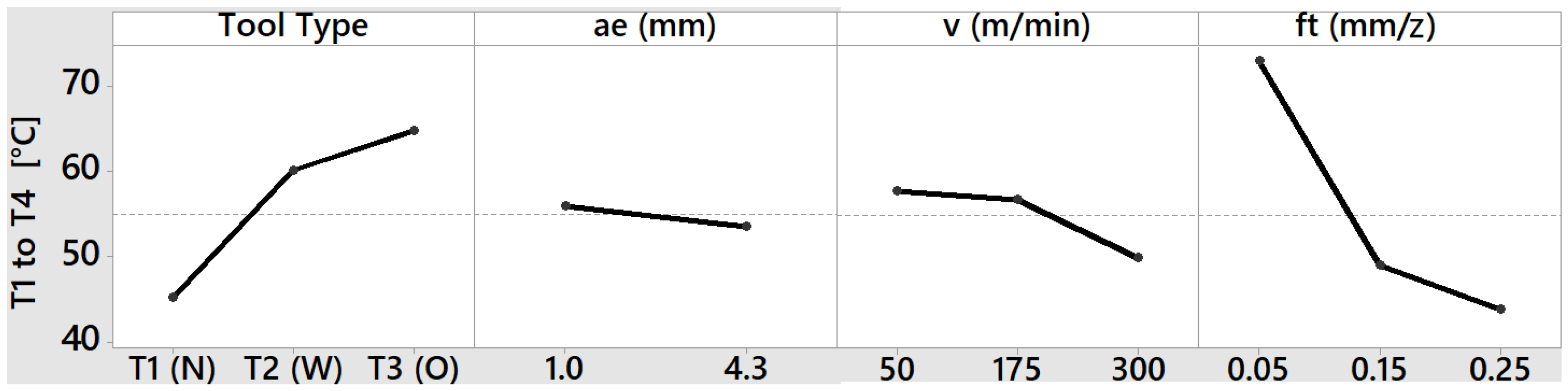
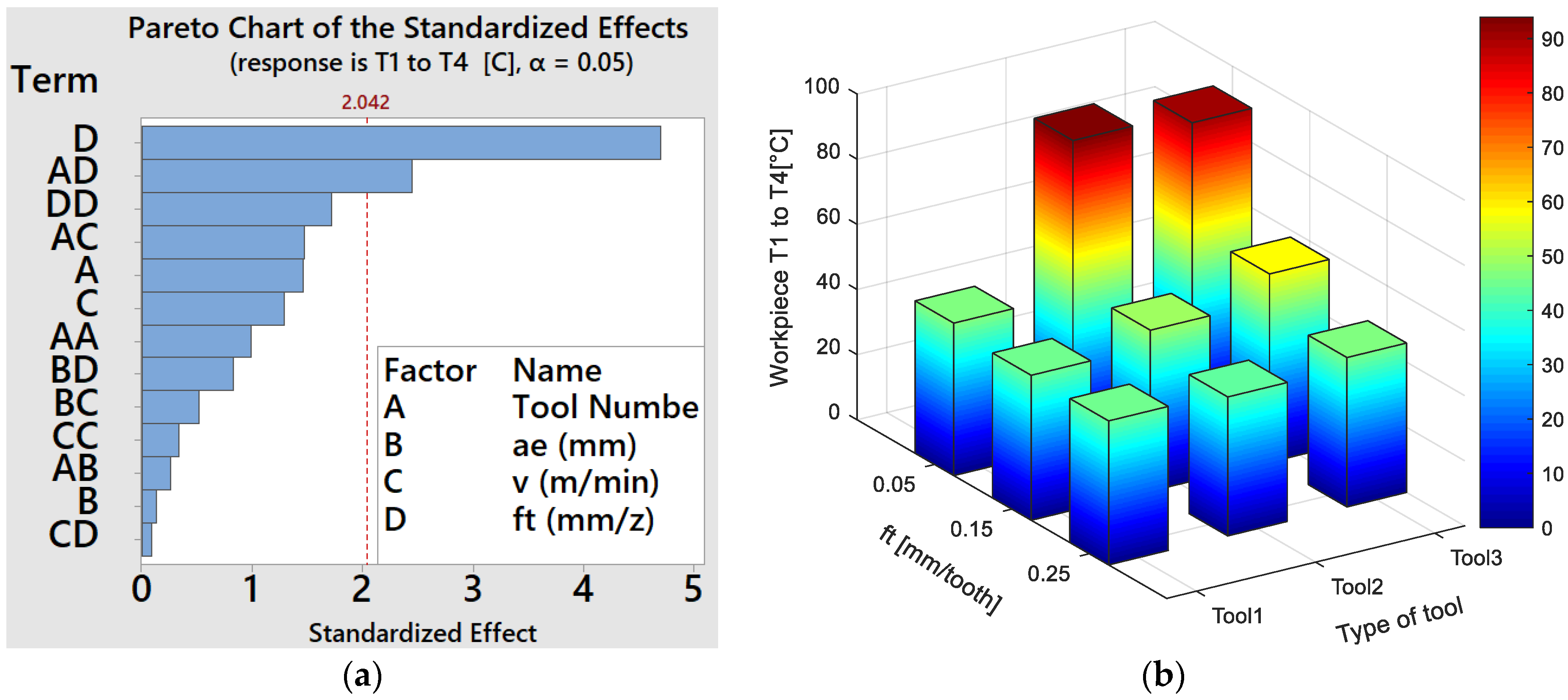
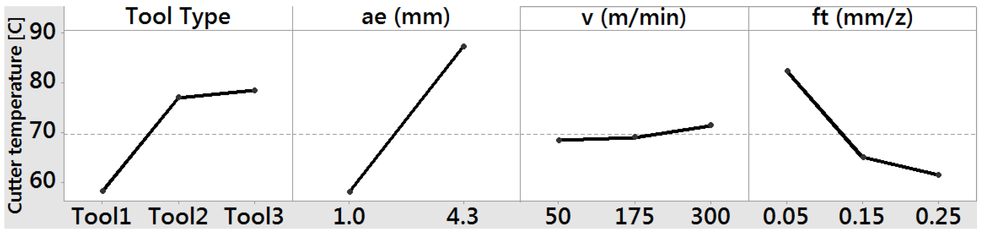
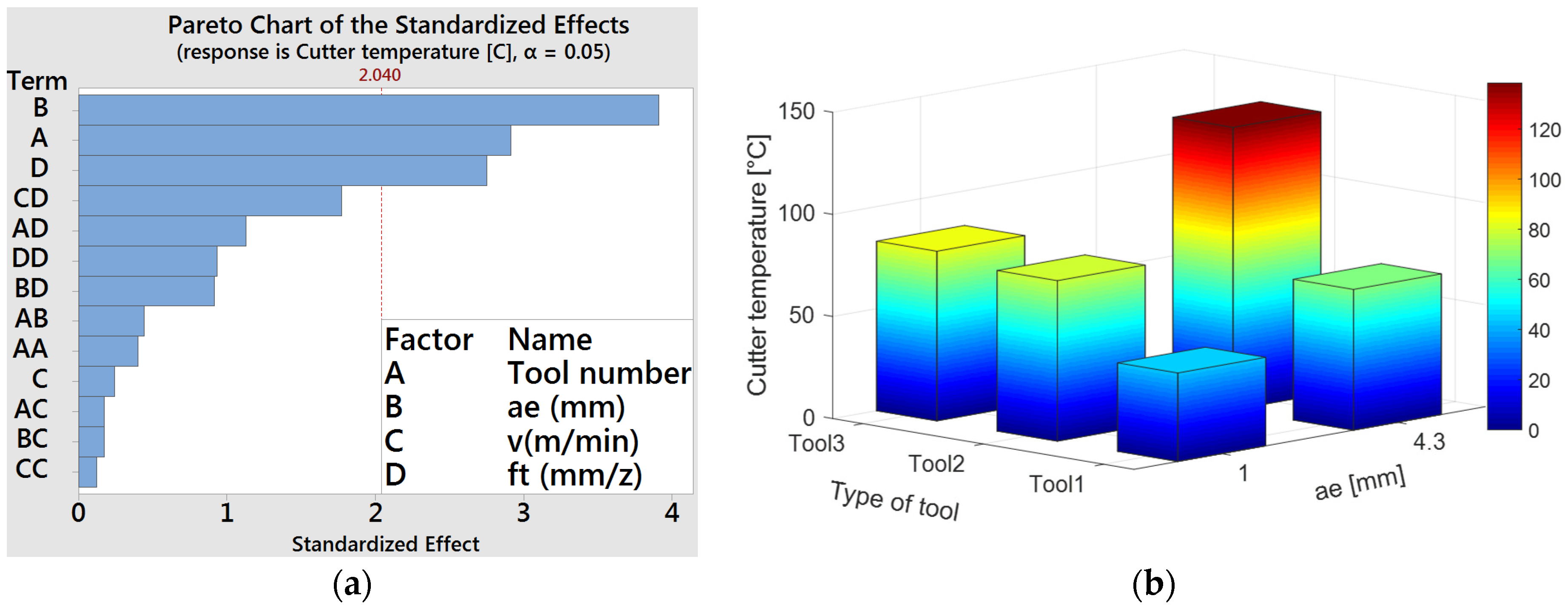
The test analysis suggests that the feed per tooth and the tool type are the factors that most influence the Ti6Al4V temperature plaque. This is contrary to the research of Y. Sun et al. and Yujing et al. [
10,
27], where studies found that the most relevant factor is the cutting speed, followed by the feed per tooth. This difference is due to the method used to estimate the cutting tool’s temperature as well as within the workpiece in both studies. In addition, their method fails to show whether the semi-artificial thermocouple can measure the temperature in both the workpiece and the cutting tool. Therein, the temperature measurement is not mentioned (location at the tool tip, or the workpiece or both). Additionally, we found that tool3 dissipates more heat through its core than does tool2. As a result, the Ti6Al4V plaque is cooler using tool3 than by machining with the other cutters. It is worth noting that both our experiments and those of Yujing et al. [
10] were carried out under dry conditions and in a down-milling cutting mode.
In the case of the [0]
8 plaque, the feed per tooth has the most significant effect on the temperature. Similar results were found by Kerrigan et al. and Sheikh-Ahmad et al. [
9,
16], but the results diverge from those of Wang et al. [
7,
11,
12]. This may be because Wang et al. followed the same methodology as Yujing et al. [
10], using a semi-artificial thermocouple. Consequently, it is hard to know if their tool–workpiece thermocouple method was estimated within the cutting tool or the workpiece since there is no physical thermocouple on the cutting edge surface. Therefore, it is difficult to assess how their semi-artificial thermocouple method, similar to a metal sheet, was able to measure the temperature of both the cutter and workpiece. In Yashiro et al. [
7], the feed per tooth was constant throughout the experiments, and its effect on the temperature cutting process could not be evaluated. On the other hand, Kerrigan’s results [
16] showed that 60% of the energy within the workpiece is due to the feed rate. However, the energy calculated was based on cutting force data and was not compared to the measurements from their thermal camera. More recently, Sheikh-Ahamad et al. [
9] studied the thermal aspects of CFRP machining and the effects of the cutting tool type and cutting parameters. Sheikh-Ahamad’s results showed that the feed per tooth is the most significant factor. This is because the cutter moves forward faster through the workpiece. As a result, the heat retention in the workpiece is lower than in the context of a low feed per tooth, which is in agreement with our results. Finally, both Sheikh-Ahmad [
9] and the present study report that the cutting speed is not a significant factor behind temperature variations within the workpiece.
Several studies have reported on the tool temperature measurement for the cutting tool temperature using different techniques, although only a few of them have obtained relevant results. In Yashiro et al. [
7], thermal cameras could not assess the tool temperature since the heat radiation saturates the thermography at the cutting point location. On the other hand, Yujing et al. [
10] estimated the cutter temperature using a semi-artificial thermocouple within the workpiece. Their statistical analysis shows that the cutter temperature has the same cutting speed trend as the workpiece, which is the most significant factor, followed by the feed per tooth, and finally, the radial depth of cut. Yujing’s results [
10] are different from those of Kerrigan’s [
16] in that the radial depth of cut is the most significant factor in the former study. This difference is due to the different methods used to measure the cutting edge temperature (semi-artificial thermocouple in Yujing et al. vs. a telemetry system for cutting tool thermocouples for Kerrigan et al. [
16] and in the present study). Moreover, Sheikh-Ahmad et al. [
9] reported that neither the cutting speed nor the feed per tooth is a significant factor, which is contrary to the findings of Yujing [
10]. Because the radial depth of cut was always kept constant in Sheikh-Ahmad’s DoE [
9], our results can therefore not be directly compared with their results. Finally, Sheikh-Ahmad et al. [
9] also studied the effects of the cutter’s physical properties (geometry and material) on the temperature of the cutter, the chip, and the workpiece. However, their results for both the cutter and the workpiece showed a higher temperature than ours. This is because their CFRP cutting length is 5 times longer than ours, even when we machined the plate under dry conditions. It is worth mentioning that our study was limited to the measurement of the cutter and workpiece temperatures, as opposed to Sheikh-Ahmad et al.’s [
9], which also covered the chip temperature.
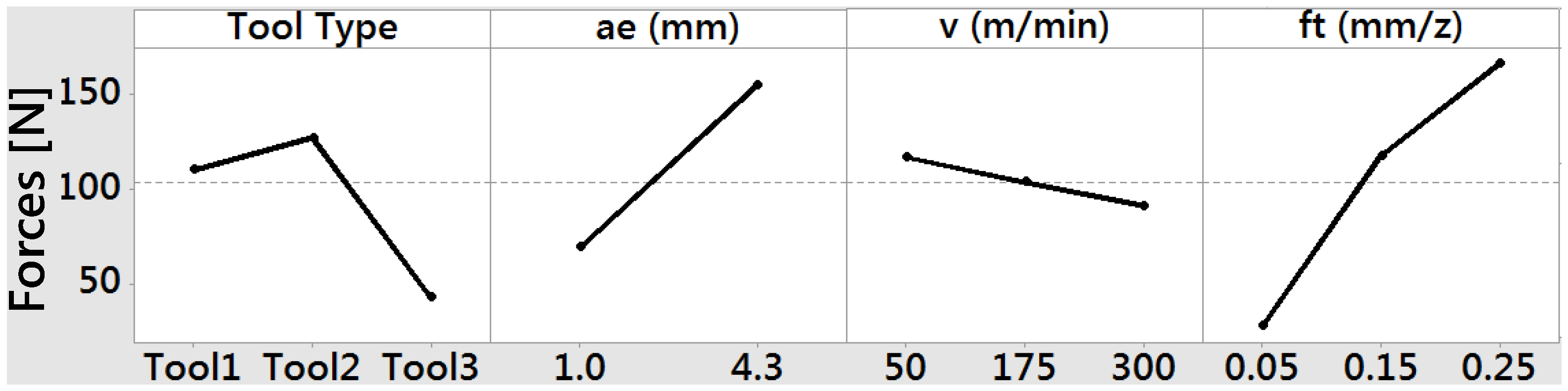
Concerning the cutting forces, the feed per tooth has the most influence on the feed, normal and axial forces for the [0]
8/Ti6Al4V stack. For the cutting forces on the Ti6Al4V plaque, Jinyang et al. and Xu et al. [
5,
6] noted that the cutting force “Fy” is greater than the thrust force “Fx” in the orthogonal cutting process of the [0]
8/Ti6Al4V stack as reported in this research. However, their machining proceeded from CFRP to Ti6Al4V or vice-versa and did not involve both materials simultaneously. Moreover, their analysis was based on the cutting speed, the fiber orientation and the depth of cut, with the feed per tooth excluded. On the other hand, Yujing et al. [
10] measured the cutting forces and observed a correlation with the temperature recorded within the titanium workpiece. Their results show that the force and temperature vary in parallel and complement each other. In addition, their study was based on determining the most relevant factor impacting the temperature generated during the machining while excluding the most significant factors in the cutting forces, which is why our results cannot be compared with those relating to their titanium plaques.
Concerning the CFRP cutting forces, our results were similar to those of Haijin et al. and Kerrigan et al. [
11,
16]. In Kerrigan et al. [
16], their results consider the resultant force composed of Fx, Fy, and Fz. On the other hand, Haijin’s cutting results [
11] show the resulting cutting force between the Fx and Fy. Both works show that the feed per tooth is the most significant factor for the CFRP plaque. However, the results are not conclusive because the plastic deformation force of the titanium plaque is greater than the brittle fracture force of the CFRP plaque. Consequently, the plastic deformation of the titanium material in the [0]
8/Ti6Al4V plaque is the most influential factor affecting the cutting force.
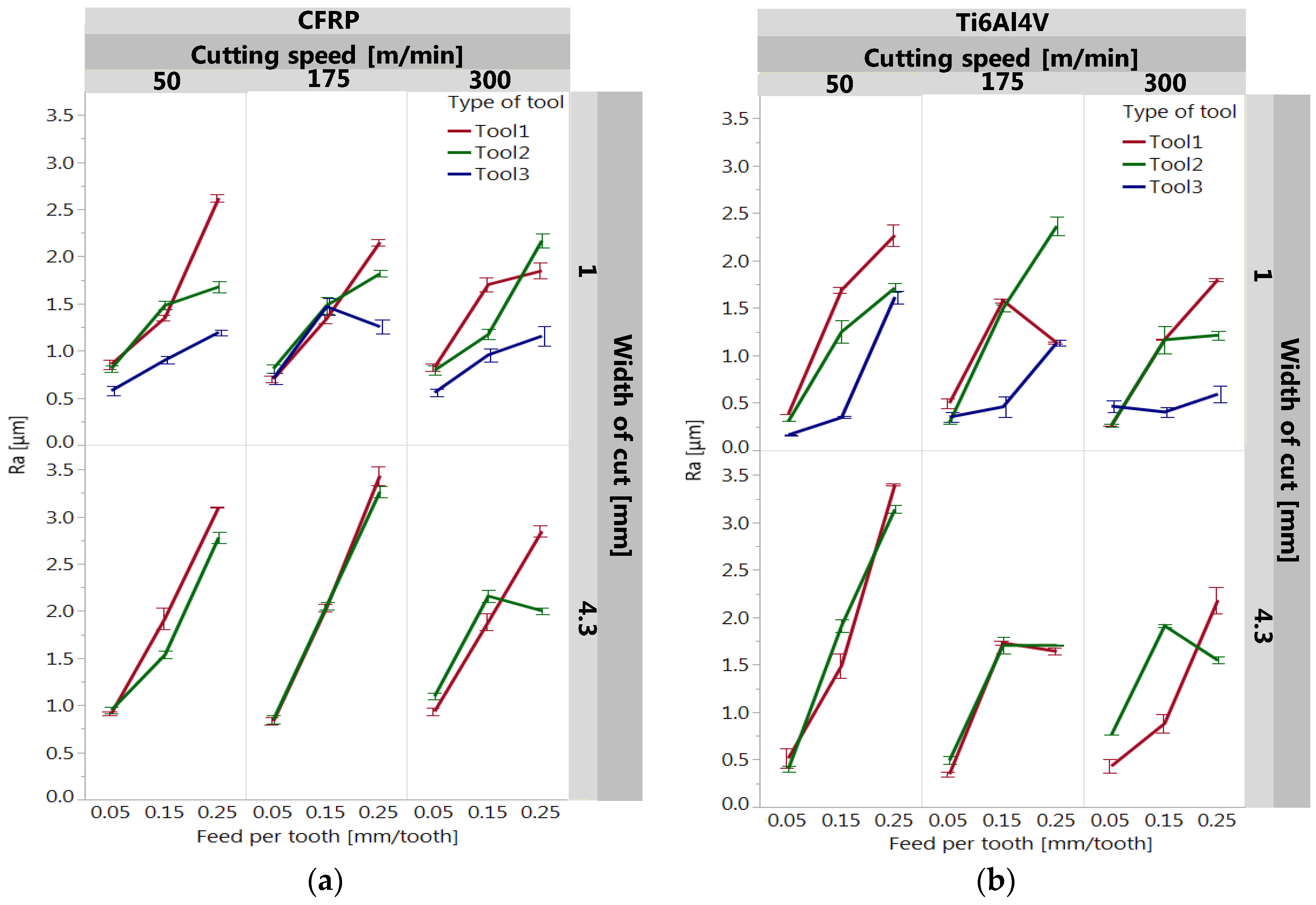
For the roughness parameter Ra, the feed per tooth is the most significant factor, which increases with an increase in the feed per tooth, and decreases slightly with an increase in the cutting speed for both the CFRP and Ti6Al4V plaques. As a result, a low feed per tooth, a high cutting speed and a low radial depth of cut are recommended to reduce the average surface roughness. In the case of the CFRP material, the result is consistent with that of Chatelain et al. [
28], in which the feed per tooth has the most significant effect. On the other hand, for the titanium, Yang et al. [
30] suggest a low feed per tooth and a low radial depth of cut and a high cutting speed, as is suggested in this study. A similar action on parameters could be used to achieve a smoother surface finish during the machining of the [0]
8/Ti6Al4V stack.
5. Conclusions
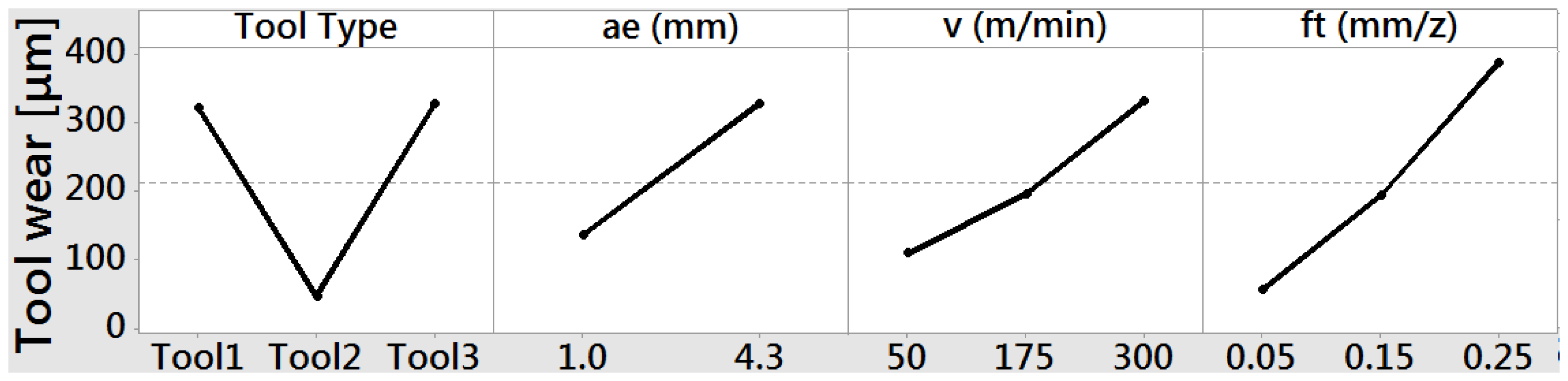
Combinations of different cutting parameters (cutting speed, radial depth of cut, and feed per tooth) and tool types were assessed using the tool–workpiece thermocouple method to measure the cutting temperature both on the cutter and within the [0]8/Ti6Al4V stack. In addition, the cutting forces, the roughness and the tool wear during the edge milling cutting process were evaluated. We found that the feed factor is the most significant factor affecting the cutting temperature for the CFRP and Ti plaques, instead of the cutting speed. Therefore, the temperature of the workpiece increases when decreasing the feed per tooth and decreases when increasing the cutting speed; however, the latter is not as significant as the feed per tooth. For the radial depth of cut, this factor is not as significant in the [0]8/Ti6Al4V stack temperature as it is in the cutter temperature. Therefore, in order to increase the workpiece machining efficiency, this research recommends using tool2 (coated TiAlN+TiAl). This is because it showed the lowest wear of the three cutters tested, the other two being tool1 (uncoated tool) and tool3 (PCD tool), and because it did not fuse with the Ti6Al4V alloys as did tool1, or chip like tool3.
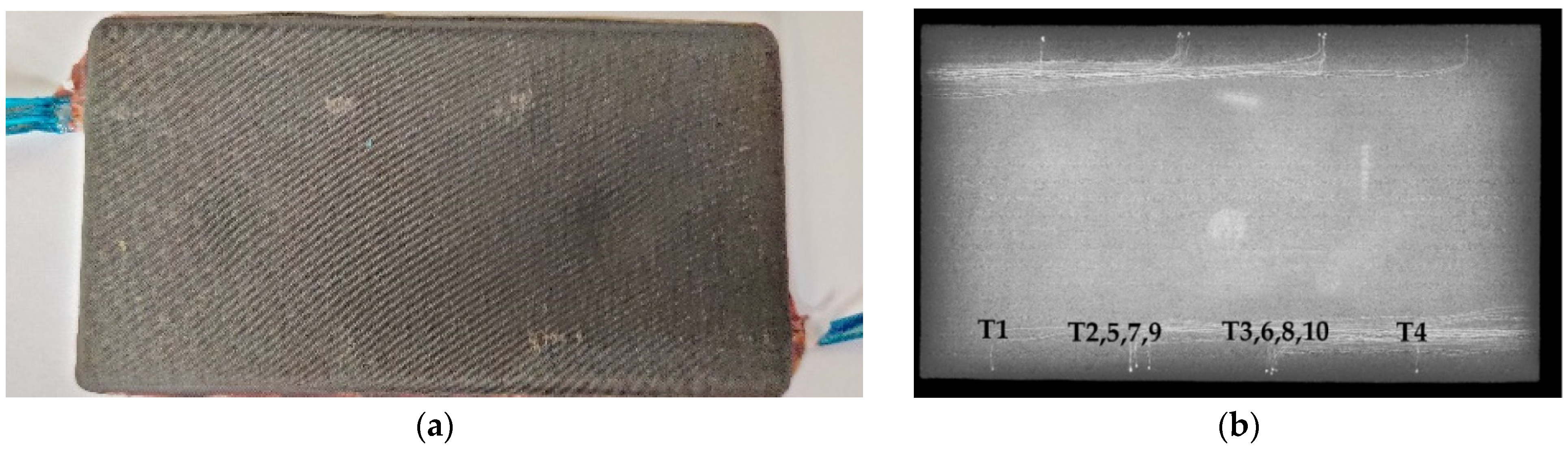
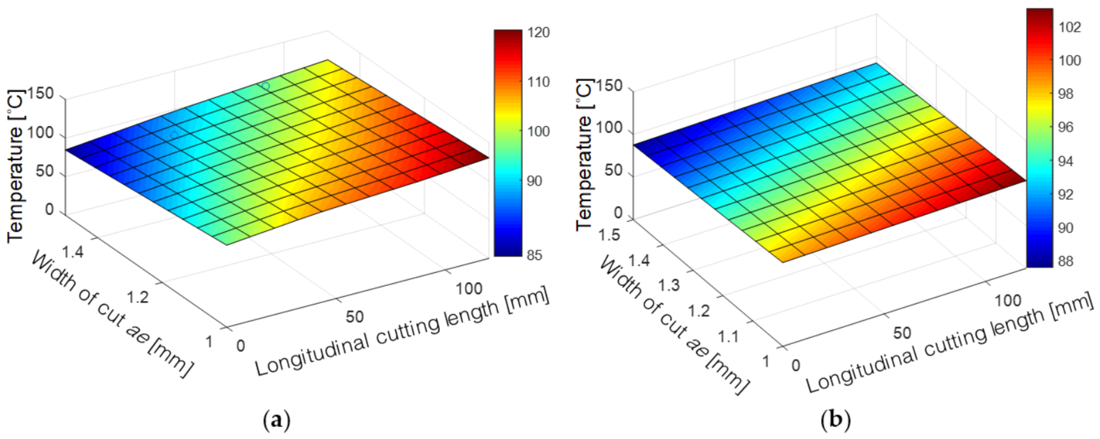
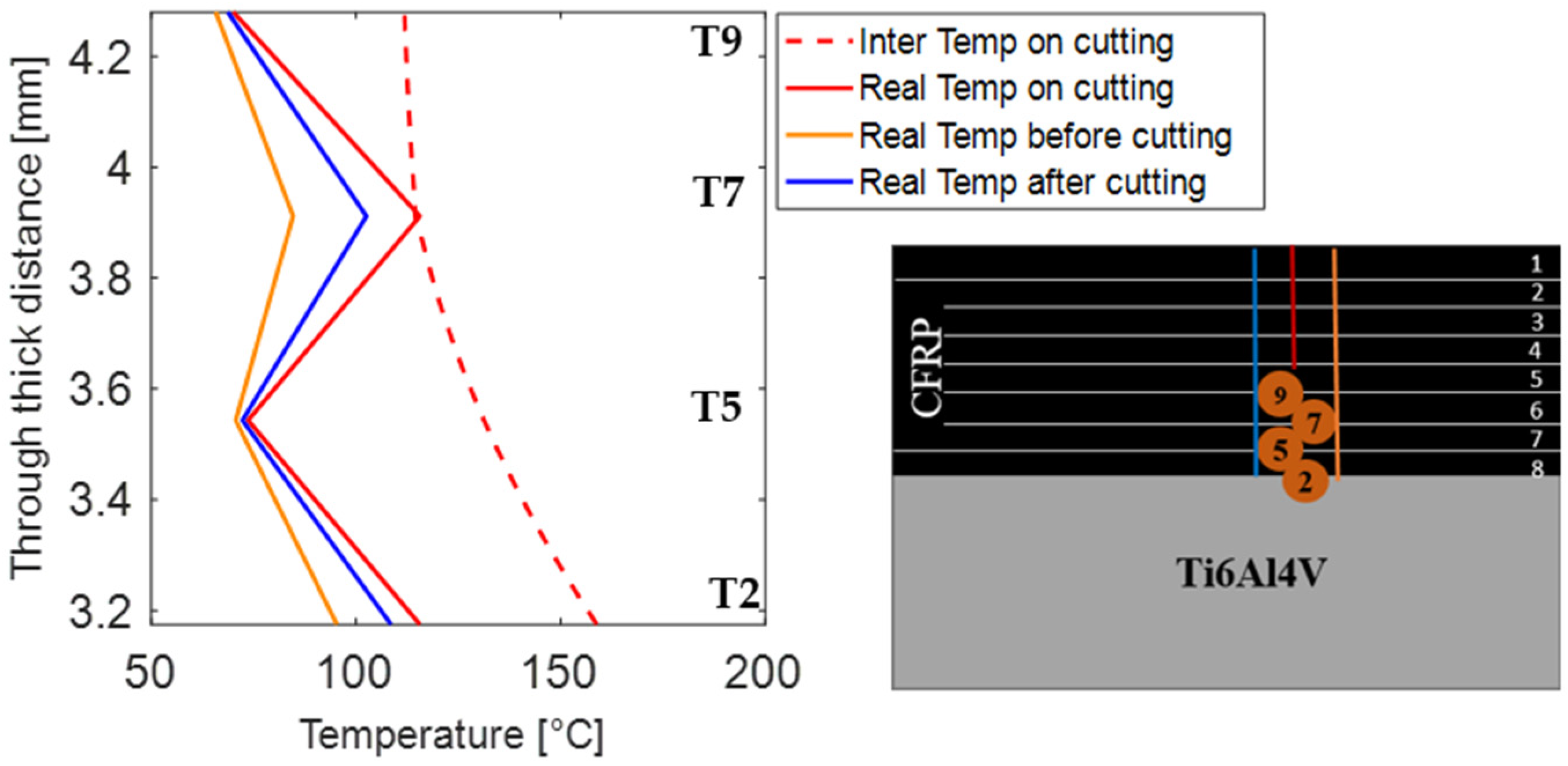
In addition, the tool–workpiece thermocouple method showed that even a few tenths of millimeters could change the temperature within the [0]8/Ti6Al4V stack. This is due to the displacement of the thermocouples within the CFRP plaque during the curing process. Moreover, due to the size of the [0]8/Ti6Al4V stack, the workpiece and cutter temperatures increase along the cutting length. Thus, future work is to set a numerical model in order to predict the temperature for real size parts using the experimental data obtained from this research.
For the cutting forces, the highest force is in the normal direction, and it increases as the feed per tooth is increased, contrary to the [0]8/Ti6Al4V stack temperature, which decreases under the same circumstance (increased feed per tooth). Therefore, the temperature and normal force have inversely proportional magnitudes. Additionally, in order to reduce the surface roughness (Ra) resulting from the edge milling of the CFRP/Ti6Al4V stack, it is recommended to use a low feed per tooth and radial depth of cut and a high cutting speed in order to compensate for the temperature within the CFRP plaque.


 ,
, 


