Article

Calcium Carbonate Particles Filled Homopolymer Polypropylene at Different Loading Levels: Mechanical Properties Characterization and Materials Failure Analysis

School of Forestry and Wildlife Sciences, Auburn University, 602 Duncan Drive, Auburn, AL 36849, USA
*
Author to whom correspondence should be addressed.
J. Compos. Sci. 2021, 5(11), 302; https://0-doi-org.brum.beds.ac.uk/10.3390/jcs5110302
Submission received: 19 October 2021 / Revised: 5 November 2021 / Accepted: 15 November 2021 / Published: 18 November 2021

Abstract

:
Calcium carbonate (CaCO3) particles have been widely used in filling thermoplastics for different applications in automotive, packaging, and construction. No agreement has been reached in the research community regarding the function of CaCO3 for enhancing toughness of homopolymer polypropylene (HPP). This study was to understand the effect of different loading levels of CaCO3 on HPP toughness, including notched and unnotched impact strength. A batch mixer was used to thermally compound CaCO3 particles with HPP at loading levels of 10, 20, 30, 40, and 50 wt.%, followed by specimen preparation using an injection molding process. The mechanical properties of the composites, including tensile, flexural, and impact were characterized. The results indicated that tensile strengths decreased significantly with increasing loading levels of CaCO3 particles while the tensile and flexural modulus increased significantly with increasing particle loadings. The composite tensile properties changed linearly with increasing CaCO3 loadings. The notched Izod impact strength of the composites was sustained by adding CaCO3 particles up to 40 wt.% while the unnotched impact strength decreased significantly with the addition of CaCO3 particles. Different deformation mechanisms between notched (fracture propagation) and unnotched (fracture initiation and propagation) impact tests were proposed to be the reason.

1. Introduction

Tailoring the mechanical properties of homopolymer polypropylene (HPP) for use in packaging, construction, and automotive industries continues to attract considerable attention [1,2,3,4,5,6,7,8,9,10,11,12,13,14,15,16,17]. The structural applications of HPP as an engineering thermoplastic are limited, due to their low impact resistance, especially at room and low temperature ranges [1,4,9,10]. HPP has shown potential of enhanced impact resistance upon inclusion of various types of fillers. Four main types of fillers have been researched extensively to improve the impact strength of HPP: rigid organic particle (wood fiber) filled PP, rigid inorganic particle (clay) filled PP, rubber blended PP, and the combination of rigid organic and inorganic particles filled PP [4,6,9,10,12,15,17]. Among the different filler categories, rigid inorganic particle filled PP showed several advantages, including raw material low cost, improved Young’s modulus, easy processing operation in commercial settings, etc. This study was to understand the mechanical behaviors of HPP filled by rigid inorganic particles at a variety of loading levels, focusing on the toughness change of filled HPP with different loadings of rigid inorganic particles.
According to the rule of mixtures, adding brittle inorganic filler particles in HPP would increase the composite modulus and decrease the toughness, i.e., impact resistance [18]. Some studies in the literatures have shown the embrittling effect of rigid inorganic fillers in polymer systems [1,19,20]. An increase in loading levels of fillers also reduces the impact resistance of the polymer system due to the reduced energy absorption capability of the matrix polymer. However, other research studies have shown increased modulus and impact resistance at the same time by adding rigid inorganic filler in polymer systems [1,18,21,22,23]. A heterogeneous system is formed by adding rigid inorganic particles in HPP with a three-dimensional interphase formed around the surface of inorganic fillers. The interphase has different structures and behaves differently than the bulk polymer matrix material due to the effect of inorganic particles [24,25]. With different loading levels of particles in the system, the volume of interphase in the composite varies, resulting in different portions of bulk polymer matrix material and different mechanical behaviors of the manufactured composites. Under external stress, the interfacial debonding mechanism and composite failure models would be expected to differ than that of a pure polymer matrix.
Mechanical behaviors of rigid inorganic particles filled polymer systems have been researched by many groups, especially for the system capable of increasing toughness of polymers [1,3,9,14,15,17,19,23,26,27,28,29,30]. The previous research indicated that the main mechanisms of toughening semi-crystalline polymer such as HPP with rigid inorganic particles incorporation involve a series of mechanical deformations, starting with stress concentration, followed by debonding of polymer/particle interface, and lastly through shear yielding of polymer matrix phase between inorganic particles [1,15,17]. Stress concentration induced debonding between polymer and particle interface was believed to be the initial plastic deformation mechanism causing the failure of the heterogeneous system [31]. This is particularly true for the PP composite system due to its low polarity and low surface energy characters compared with the polar nature of most inorganic particles [1,9,15,19,29].
When external forces are applied to rigid inorganic particles filled polymer composites, rigid particles act as stress concentrators in the matrix during deformation due to differences in moduli of polymer and rigid particles. Without strong chemical bonding between particles and polymer matrix, voids start to form between the two phases as force increases. Further increase in the external force would result in enlargement of voids through coalescence and further plastic deformation of polymer matrix phase, causing shear yielding of the matrix material [15]. At this moment, the system has the ability to absorb larger quantities of energy upon fracture, increasing toughness. A polymer must possess a high yield stress and can be yielded in the bulk phase to sustain the high toughness of the system. From the literature, additional requirements need to be fulfilled for rigid inorganic particles to function as a toughening agent in this mechanical deformation process [15,27]. These requirements have been summarized as homogeneous dispersion of particles in a polymer matrix with particle sizes less than five micrometers (μm) and particle aspect ratios close to one. With inorganic particles in the nanometers range, significant improvement in impact resistance has been demonstrated by different research groups [32,33]. The tensile moduli of the composites have also been synergistically improved.
Toughening HPP using rigid inorganic particles needs to be practiced carefully and certain requirements must be met, i.e., the particle sizes are less than five micrometers. However, a complete story of the mechanical behaviors of rigid inorganic particles filled HPP has not been unraveled, such as the effect of adding rigid inorganic particles on unnotched impact strength and the maximum loading level of particles to be added to achieve the toughening effect. The other challenge is whether we need to specifically prepare the rigid inorganic particles with sizes less than five micrometers. The objective of this study was to understand the effect of rigid inorganic particles, a commercial grade of calcium carbonate (CaCO3) particles in this specific case, at different loading levels on mechanical behaviors of HPP. The research results indicated that inclusion of CaCO3 particles without any specific preparations significantly impacted the mechanical properties of HPP. A linear relationship was observed for the tensile properties change, including modulus, strength, and elongation at yield, with the loading levels of CaCO3 in the HPP matrix. A mechanism explaining this linear relationship was proposed. The notched Izod impact strength of CaCO3 filled HPP maintained at the same level with that of HPP as the particle loading levels are up to 40 wt.%. Unnotched Izod impact strength, however, decreased significantly with the lowest loading CaCO3 particles of 10 wt.%. The different mechanisms leading to the different changes of notched and unnotched impact strengths were discussed.

2. Materials and Methods

2.1. Materials

A commercial grade HPP with a density of 0.9 g/cm3 and a melt flow rate of 20 g/10 min at 230 °C/2.16 kg was obtained to be used as the matrix material. A commercial grade of precipitated CaCO3 particles used in this study was procured from Research Product International (Radnor, PA, USA). The CaCO3 particle was delivered in a sealed plastic container with a moisture content less than 2 wt.% and the particles were stored in the sealed container to avoid absorption of moisture after each use.

2.2. Specimen Preparations

Thermal compounding of CaCO3 particles with HPP was performed using a C.W. Brabender mixer (CWB-2128, Hackensack, NJ, USA) at 205 °C. The two roller blades of the mixer, simulating the twin-screw extruder mixing action, counter-rotated at 60 rpm. The loading levels of CaCO3 used in this study were 10, 20, 30, 40, and 50 wt.% based on the weight of composites (weight of CaCO3 plus weight of HPP). The HPP pellets were first melted in the mixer at 205 °C for 8 min and then CaCO3 particles were added for mixing for another 5 min. After the thermal compounding, the mixtures were ground into pellets using a low-speed granulator (Shini Plastic Technologies Inc., Willoughby, OH, USA) with a sieve size of 3 mm. The mixture pellets were then dried and injection molded into testing specimens according to the ASTM D638 (Type I), ASTM D790, and ASTM D256 using a benchtop injection molding machine (Medium Machinery, LLC., Woodbridge, VA, USA). The injection molding temperature was set up at 195 °C with an injection pressure of around 90 MPa. Virgin HPP was also mixed using the same process and then the mixed HPP specimens were injection molded for mechanical tests as a control.

2.3. Mechanical Property Tests

Tensile, flexural, and impact tests of CaCO3 filled HPP composites were performed according to ASTM D638, ASTM D790, and ASTM D256. Tests were conducted in an environmentally conditioned room at 23 ± 2 °C and 50 ± 5% relative humidity (RH). Tensile tests were performed using a Zwick-Roell universal testing machine (Kennesaw, GA, USA) with 10,000-N load cell. An Epsilon axial extensometer SN87275 (Jackson, WY, USA) was used to measure the strain during the tensile test. The speed of testing was 5 mm/min and the strain rate at the start of test is 0.1 min−1. The tensile strength, percent elongation at yield and modulus of elasticity (MOE) were obtained. Flexural tests were conducted with a 500-N load cell attached to a Mark-10 ESM750s (Copiague, NY, USA) flexural testing fixture. Flexural tests were carried out using both procedures A and B specified in ASTM D790 and the outer fiber strain rates for procedures A and B are 0.01 and 0.1 min−1, respectively. Under the two strain rates, the specimens did not yield or break and the flexural properties, including flexural strength and MOE, were reported at 5% strain using procedure B. Izod impact testing specimens were prepared using a manual CEAST notcher (Instron, Norwood, MA, USA) and impact tests were performed on notched and unnotched composites specimens using an XJUD Digital Charpy Izod Impact Testing Machine (Deli Group CO. Ltd., Ningbo, China). At least five replicates were tested for each composite formulation to determine the tensile and flexural properties and ten specimens were used to obtain the Izod impact strength. Mixed HPP specimens were tested using the same procedures. The average values for the mechanical properties of mixed HPP and CaCO3 filled HPP composites were reported. Statistical analysis of the mechanical properties was performed and a significance level of 0.05 was employed.

2.4. Melt Flow Rate (MFR) Measurement

The MFR of the manufactured composites was determined using a Melt Flow Rate Tester (Techtongda, Markham, ON, Canada) according to the ASTM D1238 on pellet samples obtained from grinding of the mixture after mixing. The measurements were conducted at 230 °C with the weight of 2.16 kg. Five replicates were measured for each sample and weighed to the nearest 1 mg. The standard melt flow rate number with the units of g/10 min was reported.

2.5. Scanning Electron Microscopy (SEM)

The CaCO3 particles and the fracture surfaces of impact tested specimens were sputter coated with gold for 60 s in a Q150R ES sputter coating device acquired from Electron Microscopy Sciences (Hatfield, PA, USA). Before the sputter coating process, CaCO3 particles were deposited on conductive carbon tapes, trying to disperse each individual particle for better conductivity during SEM characterization. The calcium carbonate particles and the fracture surfaces were examined using a Zeiss Evo 50VP scanning electron microscope (Oberkochen, Germany) at 20 kV voltage. The morphologies of calcium carbonate and the composite fracture surfaces were reported.

3. Results and Discussion

3.1. Morphology of Calcium Carbonate Particles

The morphologies of calcium carbonate particles were examined using SEM and the micrographs at different magnifications are shown in Figure 1. Irregular shape solid particles with aspect ratios around one or greater were observed. The majority of the particle sizes of CaCO3 particles ranged from less than one micrometer to around 10 μm. Large particles with the longest dimensions of around 25 μm also exist. Sharp edges were also observed on most of the particles.

3.2. Tensile and Flexural Properties of CaCO3 Particles Filled HPP

The tensile properties of mixed HPP and CaCO3 particles filled HPP were summarized, and the results are shown in Figure 2. The detailed numbers and statistical analysis results are shown in Table 1. Different letters of A, B, C, D, E, and F in 
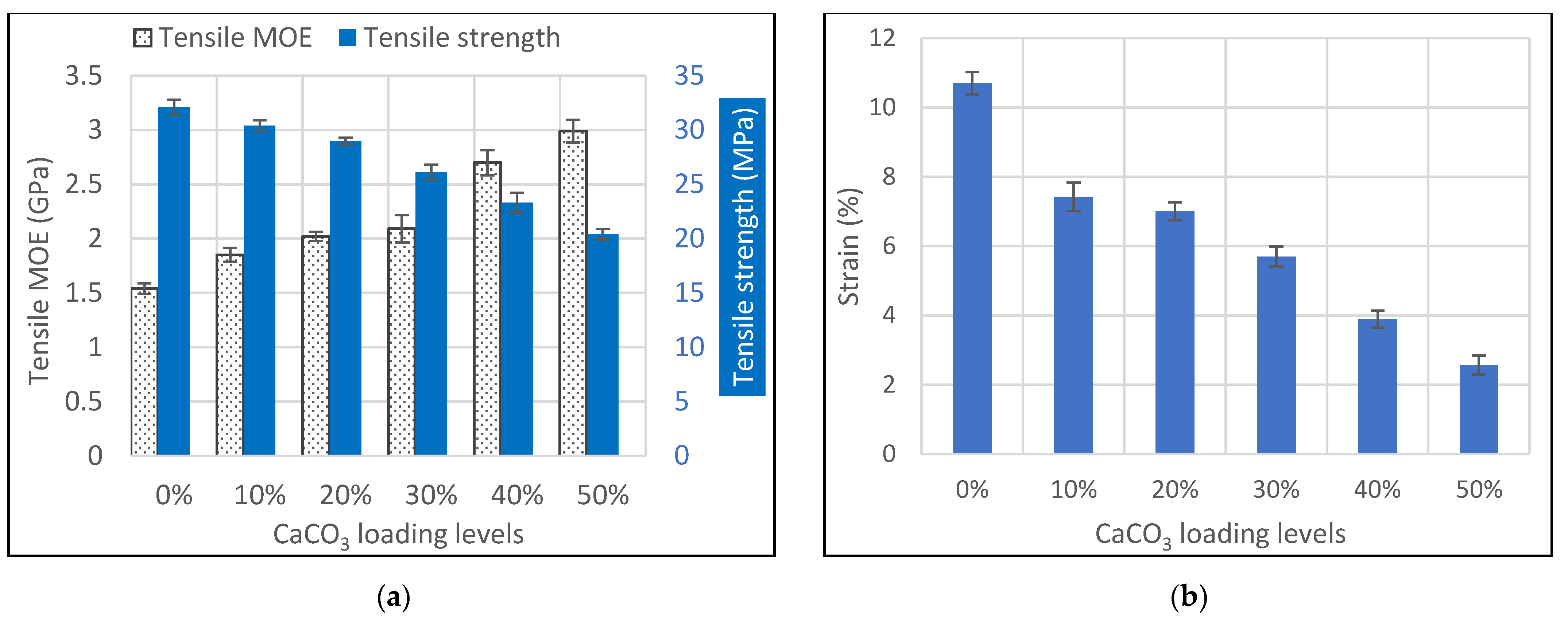
Table 1 represent significant differences in the mechanical results. After the batch mixer processing, HPP has an MOE and tensile strength of 1.54 GPa and 32.1 MPa, respectively (Figure 2a and Table 1). Addition of CaCO3 particles at loading levels of 10, 20, 30, 40, and 50 wt.% into HPP through the batch mixer increased the tensile MOE of the composites to 1.85, 2.02, 2.09, 2.70, and 2.99 GPa, which are 20, 31, 36, 75, and 94% higher than that of pure HPP, respectively. On the other side, tensile strengths significantly decreased from 32.1 MPa to 30.4, 29, 26.1, 23.3, and 20.4 MPa with inclusion of 10, 20, 30, 40, and 50 wt.% CaCO3, representing decreases of 5, 10, 19, 27, and 36%. The elongations at yield (strain) during the tensile testing were also characterized using an extensometer and the data is shown in Figure 2b and Table 1. When compared with HPP, inclusion of CaCO3 at loading levels of 10, 20, 30, 40, and 50 wt.% significantly decreased the strain at yield from 10.7% to 7.4, 7.0, 5.7, 3.9, and 2.6%, which are around 31, 35, 46, 64, and 76% lower than that of pure HPP.
After injection molding, dispersed CaCO3 particles were packed with HPP under high pressure in an aluminum mold followed by cooling. When the specimens were cooled to a lower temperature, specimen shrinkage in all the dimensions occurred in the mold and less shrinkage was observed for the CaCO3 particles filled HPP specimens than that of pure HPP specimens. During specimen cooling, CaCO3 particles in the composites restricted the movement of molecular chains of HPP, decreasing the shrinkage. Simultaneously, the particles also interrupted the crystallization process the composites went through during cooling and the mechanical behaviors of CaCO3 particles filled HPP would therefore change. After settling the specimens for a period at room conditions, the polymer phase approached an equilibrium without any further deformation and polymer crystallization completed. HPP has a glass transition temperature lower than room temperature and polymer molecular chains can still move without significant effect on material properties. Under this approximate equilibrium, residual stress could be existed on the CaCO
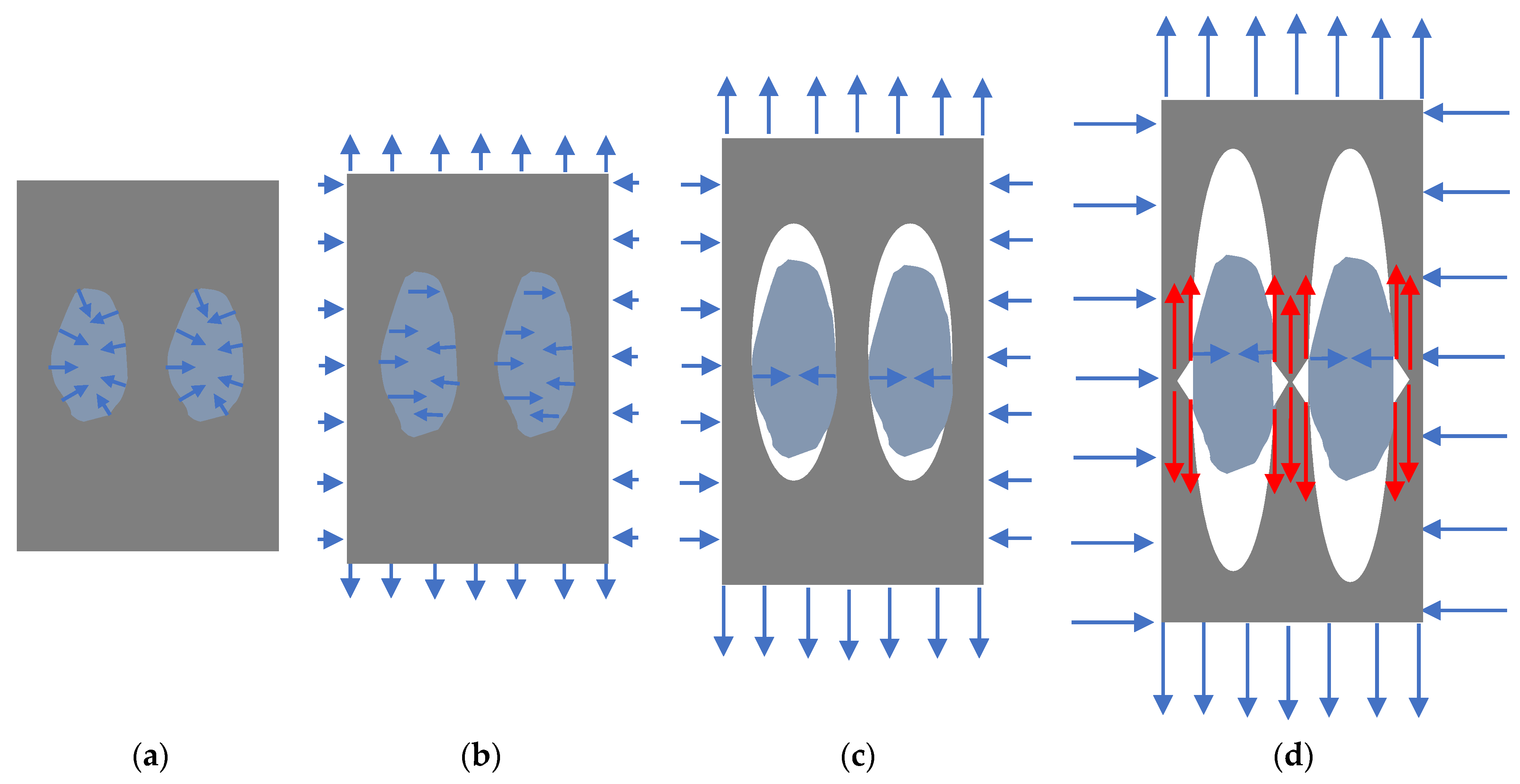
3 particle which is applied by polymer molecules due to polymer shrinkage during cooling. Therefore, CaCO3 particles existed in the composite system bearing residual compression stresses with a small strain because of a high MOE (Figure 3a). All the compression stresses are normal to the particle surface at all points.
Under tensile load for the equilibrated composite system, specimens of HPP and CaCO3 particle filled HPP responded with an initial deformation in the elastic region. In this initial phase of the elastic deformation zone, stress inside the whole specimen is uniform and initial uniform strain is generated in a very small magnitude according to the classical mechanics. In this stage, external load released the residual stress applied on CaCO3 particles along the tensile load direction, returning the particle to the zero-stress status and cancelling the strain in the tensile load direction which was caused by the initial residual stress (Figure 3b). Additionally, tensile load also applies shrinking force perpendicular to the tensile load direction on the specimen due to Poisson’s ratio effect, compressing the CaCO3 particles cross the tensile load direction, simultaneously.
As the external tensile load increases the elastic strain of polymer phase would be much larger than that of CaCO3 particle because MOE of CaCO3 particle is much greater than that of HPP. With the same grip separation in this strain range, the deformation of CaCO3 particles cannot catch up with the deformation of HPP. Starting at this moment, polymer phase begins to separate with CaCO3 particles and debonding at a point of the interface occurs first along the tensile load direction. For an irregular shape rigid particle embedded in the polymer matrix, the farthest point on the particle surface in the tensile load direction debonds first, forming a void, and then the debonding slowly spreads along the particle surface to all directions. The debonding continues until voids form at all the interface perpendicular to the tensile load direction (Figure 3c). At the same time, as the specimen elongates in the direction of load, shrinkage continues to occur in the direction perpendicular to the load. Therefore, the polymer matrix would hold the rigid particle at the widest point and applies compression stresses on the particle (Figure 3c). This is the second stage deformation of the composite under tensile load. During this process, CaCO3 particles interfere with the mechanical responses of the composites under tensile stress and the dominant deformation mechanism is still in the elastic range, mostly occurring with the polymer phase. The tensile MOE characterization results shown in Figure 1 and Table 1 demonstrated the interferences from CaCO3 particles and tensile MOE increased with the interferences. When the loading levels of particles increased from 10 to 50 wt.%, more surface area of CaCO3 particles became involved in this interference, resulting in greater tensile MOE of the composites. At this second stage of elastic deformation, a shear force could also be generated on the particle if the widest dimension of the particle is not aligned with the transverse direction of the specimen, rotating the CaCO3 particles in the matrix during the deformation process.
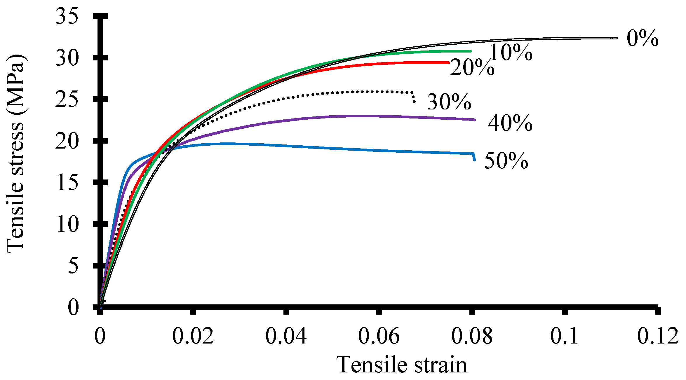
These phenomena of elastic deformation of the specimen can also be indicated by the stress-strain curves of the tested specimen and a representative stress-strain curves for each sample is shown in Figure 4. In this elastic deformation range, higher loading CaCO3 particles in the composite needed a proportionally higher stress to reach the same strain assuming a similar uniform dispersion of these particles in HPP. Simultaneously, higher loading particle composites also required greater stresses to reach the initial phase of the elastic deformation zone (Figure 3b). A linear regression analysis on the tensile MOE (Y) versus CaCO3 loading levels (X) showed a linear relation below:
Y = 0.28 X + 1.21 (R2 = 0.94)
In this relationship, tensile MOE increased linearly with particle loading level, which verified the theory proposed above.
As a greater external tensile load continues to be applied to the testing specimen, plastic deformation of the HPP system dominates the deformation process with increased strain and the composite deformation passed the elastic zone. Rigid CaCO3 particles do not go through the plastic deformation in this case. At this stage, the slopes of the stress-strain curves start to decrease until the yield point of the composites is reached (Figure 4). At the point of composite yielding, rupture of the plastic matrix occurs, and tensile strength is obtained. During the plastic deformation range, additional tension stress is applied to the polymer phase in the transverse direction of the specimen by the CaCO3 particles. This tension stress is the reaction stress to the stress applied the CaCO3 particles. Therefore, the yielding and rupture of the polymer phase is achieved by the combination of the external tension load and the reaction tension stress from CaCO3 particles (Figure 3d). Sharp edges of CaCO3 also play a role in yielding the composite under tensile load.
At the yielding point, the tensile stress (strength) is calculated by dividing the external force with the cross-section area of the specimen and the force is only loaded to the polymer phase since there is a complete separation between polymer phase and CaCO3 particles in the loading direction. For the same cross-section area with the same amount of polymer phase, the tensile strength would be the same. When the loading levels of CaCO3 in the composites increased from 10 to 50 wt.%, the amount of polymer phase in the cross-section decreased with a proportional rate and the tensile strength would decrease linearly with CaCO3 particle loading levels. The experimental results of the tensile strength are shown in Figure 1a and Table 1. Data analysis of the tensile strength showed a linear relationship between the tensile strength (Y) and the CaCO3 particle loading level (X):
Y = −2.36 X + 35 (R2 = 0.98)
Other factors, such as particle distribution and dispersion and the reaction tension stress applied by particles had a minor effect on tensile strength.
The tensile strain at yield behaved the same as the tensile strength (Figure 1b) and it decreased significantly with increasing CaCO3 particle loading levels. Along the tensile load direction, portion of polymer molecular chains was replaced by the CaCO3 particles, and the strain needed to achieve the tensile strength would decrease proportionally. The linear relationship between the strain at yield (Y) and CaCO3 particle loading level (X) is shown below.
Y = −1.50 X + 11.5 (R2 = 0.96)
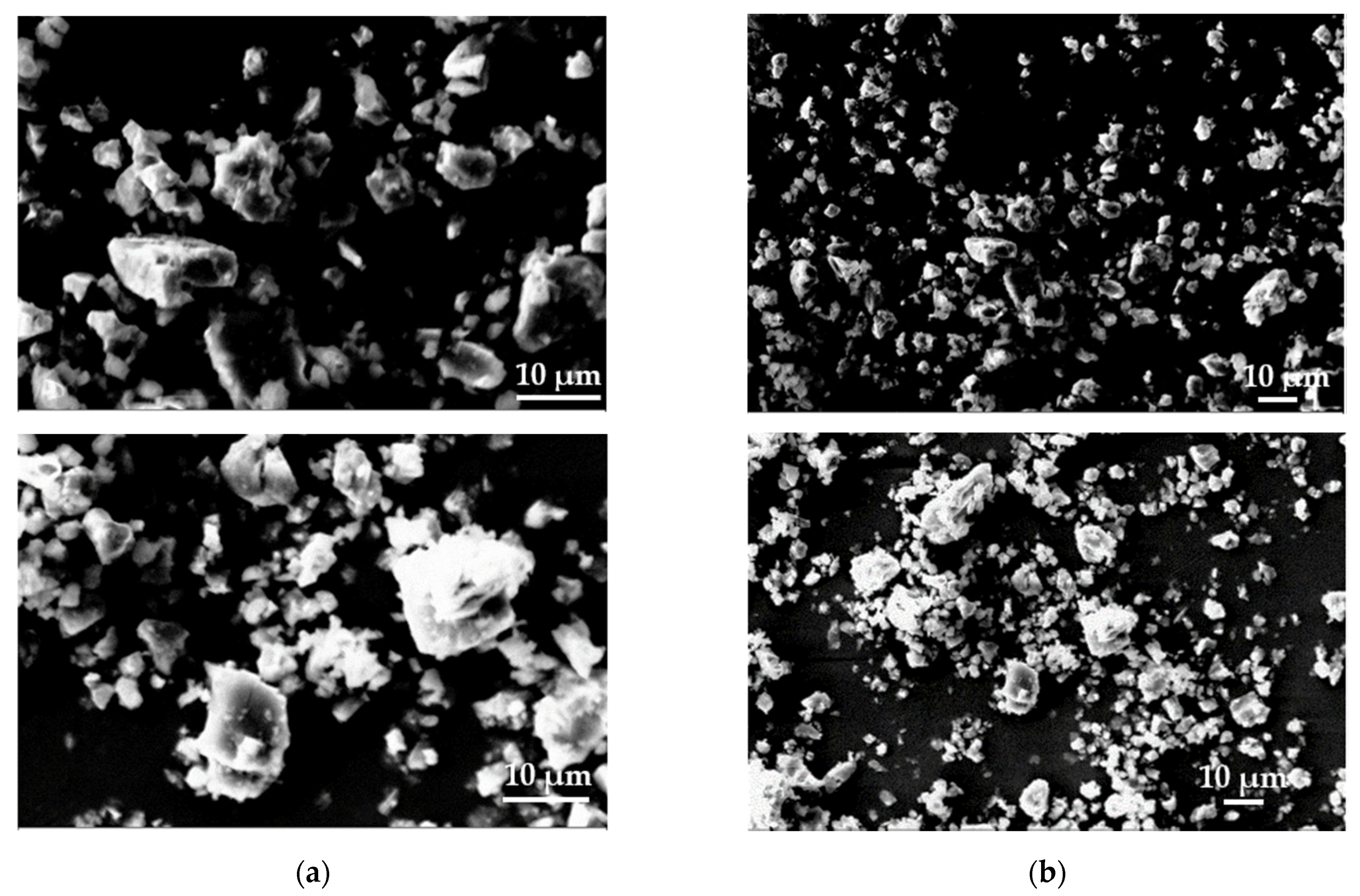
In summary, the tensile properties of CaCO3 particles filled HPP changed linearly with particle loading levels. In our proposed explanation, the particle morphologies, including shape and size, and quantity play critical role affecting the tensile behaviors of the composites.
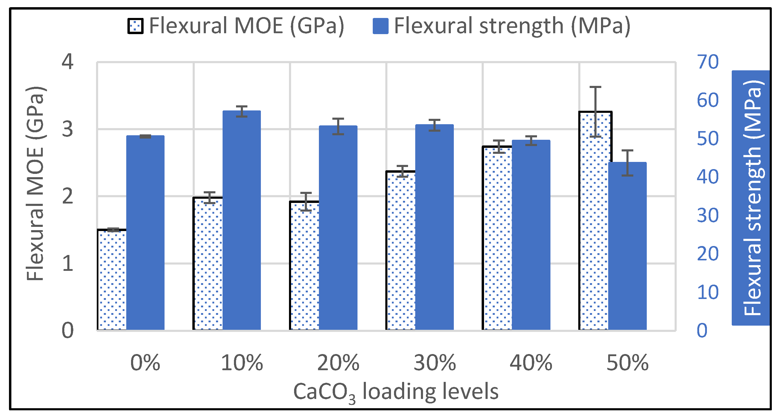
The flexural properties of pure HPP and CaCO3 particles filled HPP, including flexural MOE and strength, are shown Figure 5. Table 1 shows the detail numbers and the statistical analysis results. During the flexural tests, all the specimens did not yield or break at 5% strain limit at two different testing speeds. The flexural strength at 5% strain obtained using the rate of straining of the outer fiber of 0.1 mm/mm/min was reported in this study. The flexural MOE and strength of HPP are 1.50 GPa and 50.6 MPa. Adding CaCO3 particles into HPP significantly increased the flexural MOE and the MOE at 10, 20, 30, 40, and 50 wt.% particle loadings are 1.98, 1.92, 2.37, 2.74, and 3.26 GPa, which are 32, 28, 58, 83, and 117% greater than that of pure HPP, respectively. The increase of flexural MOE is common when including rigid particles in polymer composites [34]. The flexural strength of the composites increased from 50.6 MPa for pure HPP by inclusion of the CaCO3 particles at 10, 20, and 30 wt.% and the flexural strengths are 57.1, 53.2, and 53.5, respectively. There is no significant difference on flexural strength for the composite with 40 wt.% CaCO3 particles when compared with HPP. Adding 50 wt.% CaCO3 significantly decreased the flexural strength of HPP. The deformation of the specimen during flexural test is complex, combining the tension on the bottom surface of the specimen and the compression at the top surface. In the particle loading level ranges of 10, 20, and 30 wt.%, the compression strength is increased on top surface. Simultaneously, the stress needed for the bottom surface to reach 5% strain is increased, resulting in the increase of flexural strength of the composites. At the 40 and 50 wt.% CaCO3 loadings, a larger portion of the composites surface contained interfaces between CaCO3 particle and polymer phase and a lower stress was required to achieve a 5% strain on the bottom surface than that needed in composites having 10–30 wt.% particles, resulting in a lower flexural strength. At the 50 wt.% loading level, the flexural strength is also lower than that of HPP (Figure 5).

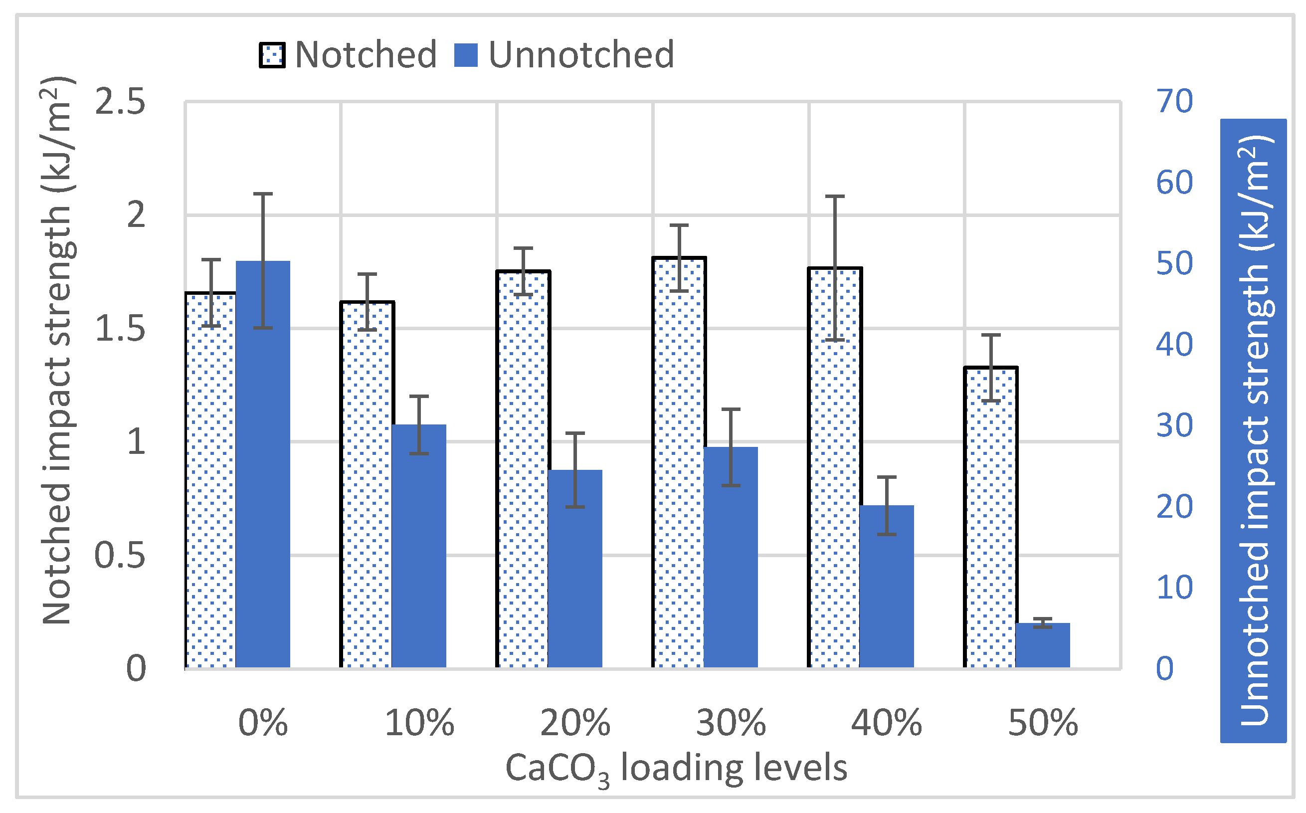
3.3. Impact Properties of CaCO3 Particles Filled HPP

The Izod impact strengths tested notched and unnotched for all the composites are shown in Table 1 and Figure 6. The unnotched specimens were tested with the v-notch faced backward to the hammer load. The notched and unnotched impact strengths for pure HPP are 1.66 and 50.3 kJ/m2. For notched impact tests, the impact strengths for composites with CaCO3 particle loading levels of 10, 20, 30, 40, and 50 wt.% are 1.62, 1.75, 1.81, 1.76, and 1.32 kJ/m2. The statistical analysis indicated that the impact strengths of composites with CaCO3 particle loading levels of 10, 20, 30, and 40 wt.% are not significantly different than that of pure HPP (Table 1). At 50 wt.% loading, the notched impact strength (1.32 kJ/m2) is significantly lower (20%) than that of pure HPP (1.66 kJ/m2). For unnotched impact tests, the composites containing the rigid particles have significantly much lower impact strengths and the impact strengths at 10, 20, 30, 40, and 50 wt.% loading levels are 30.1, 24.5, 27.3, 20.1, and 5.67 kJ/m2, which are 40, 51, 46, 60, and 89% lower than that of pure HPP (50.3 kJ/m2) (Table 1 and Figure 6).
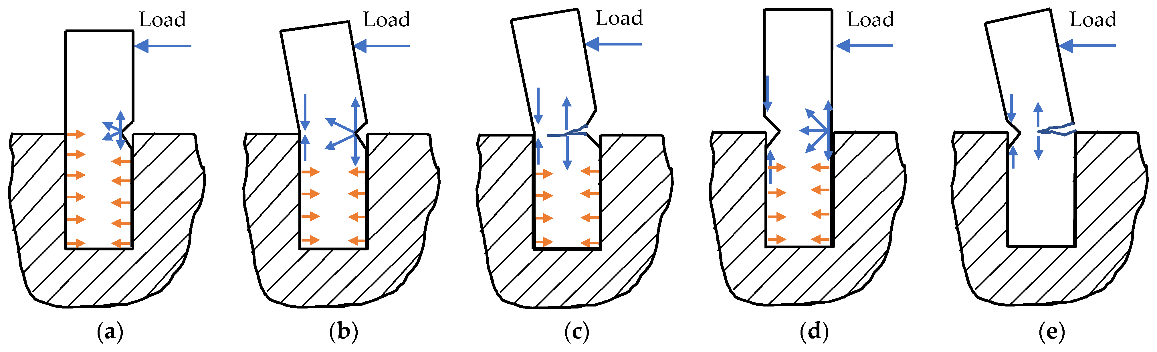
During the notched Izod impact test, the notching side of the specimen faced the impact load (Figure 7). The bottom half of the specimen was held tight by the specimen holder and compression forces were applied to the specimen during the test (Figure 7a). When the hammer contacted the specimen, a high magnitude of impact load applied strong stress to the notch tip. The effect of the stress can be simplified as tension and compression to the notch tip (Figure 7b). The tension force facilitated the fracture initiation which could be induced by notching process and the compression force helped to propagate the fracture toward the center of the specimen transversely (Figure 7c). Once fracture started to propagate (Figure 7c), tension force would be the main driver moving the fracture front boundary toward the backside of the specimen. The backside of the specimen was always under compression until the complete failure of the specimen. The notched Izod impact strength was then calculated through dividing the energy to break the specimen by the specimen cross-section area. The energy to fracture the HPP sample would be the energy to overcome the elastic and plastic deformation of HPP, i.e., the work needs to be done to create the new surfaces of HPP.
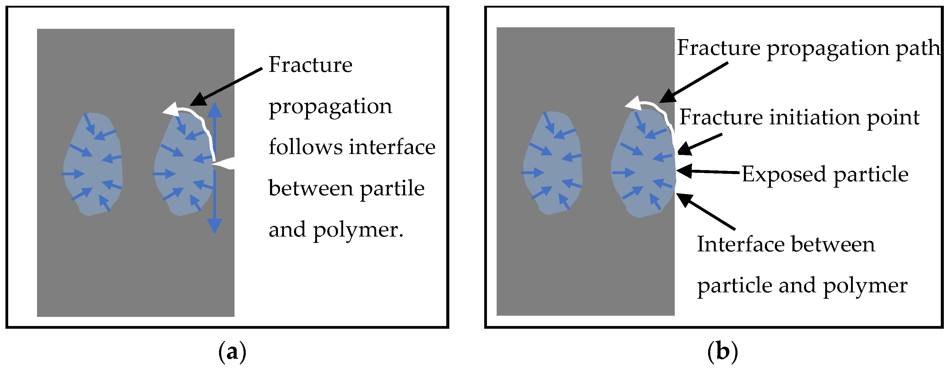
In CaCO3 filled HPP composites, fracture can only occur in the polymer phase or at the interface between the particles and polymer. To be fractured, a polymer must go through elastic and plastic deformation zones. Assuming a same surface area (Atotal) was created after specimen fracture for pure HPP and CaCO3 particles filled HPP composites, there would be less deformation energy for the polymer phase in CaCO3 particles filled HPP composites because partial fracture surface would be replaced with CaCO3 particle surface (Afiller). Under this circumstance, the energy for fracturing CaCO3 particles filled HPP composite would be lower and less amount of polymer has been fractured, resulting in lower impact resistance of the sample. The surface area for polymer fracture for CaCO3 filled HPP composite is (Atotal − Afiller). Another premise for the theory to be true is that much less energy is needed to separate CaCO3 particle and polymer matrix compared with fracture of polymer matrix. This is a reasonable estimation for this specific case because there was no chemical modification on the surface of CaCO3 particles. Alternatively, we can say that the work needed to separate unit interface of CaCO3 particle and polymer is lower than that for creating unit fracture surface of the polymer.
During the fracture propagation process, however, CaCO3 filled HPP behaved differently. The rigid particle functioned as a blocker for the fracture propagation. Therefore, the fracture front of the CaCO3 particles filled HPP followed a different path than pure HPP. The fracture front moved along the interface between CaCO3 particles and polymer matrix (Figure 8a), followed by fracturing the pure polymer phase between CaCO3 particles. With this new fracture path, a much larger fracture surface area (Afiller’ > Afiller) was created for CaCO3 particles filled HPP when compared with pure HPP.
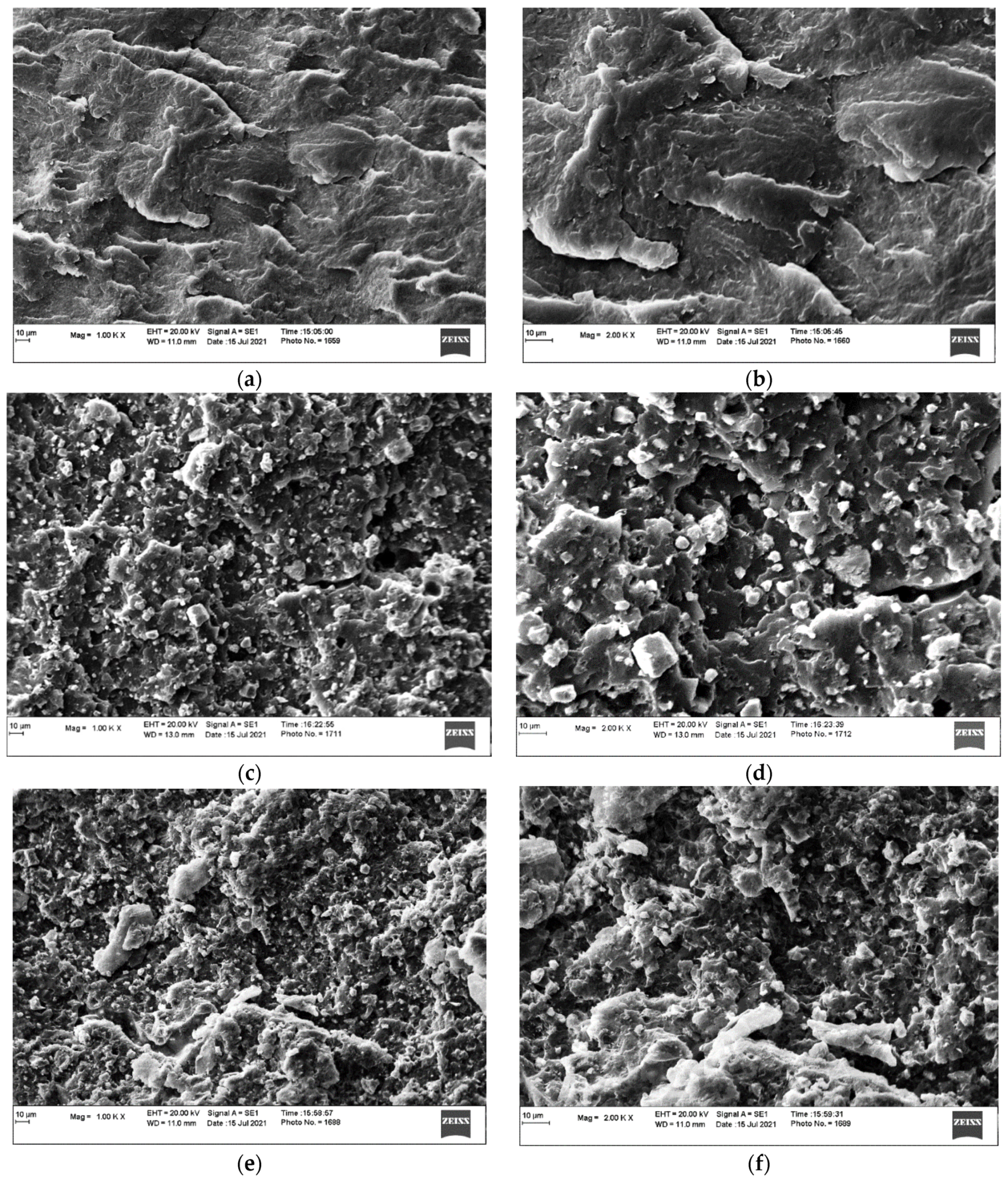
The different fracture surfaces can be demonstrated by the SEM micrograph observations (Figure 9) and much coarser fracture surfaces were observed for CaCO3 filled HPP samples. Simultaneously, separation between the particles and HPP can be easily identified (Figure 9) and this can verify that the work used to separate CaCO3 particle from HPP is lower than that to fracture HPP. In this case, the work used to create the new surface area of Afiller’ can compensate the work needed to create fracture polymer surface area of (Atotal − Afiller) and comparable impact strength can be achieved using CaCO3 fillers when compared with pure HPP (Figure 6 and Table 1). The phenomena of maintaining the notched Izod impact strength of HPP using up to 40 wt.% CaCO3 particles are explained. At the 50 wt.% CaCO3 particles loading level, a large portion of polymer was replaced by CaCO3 particles and the work for creating polymer fracture surface area of (Atotal − Afiller) cannot be made up by the work creating the new surface area of Afiller’. The surface area of (Atotal − Afiller) is the polymer fracture surface area which has been replaced when 50 wt.% CACO3 particles are included in the composite. Therefore, a lower Izod impact strength was observed at 50 wt.% loading level of CaCO
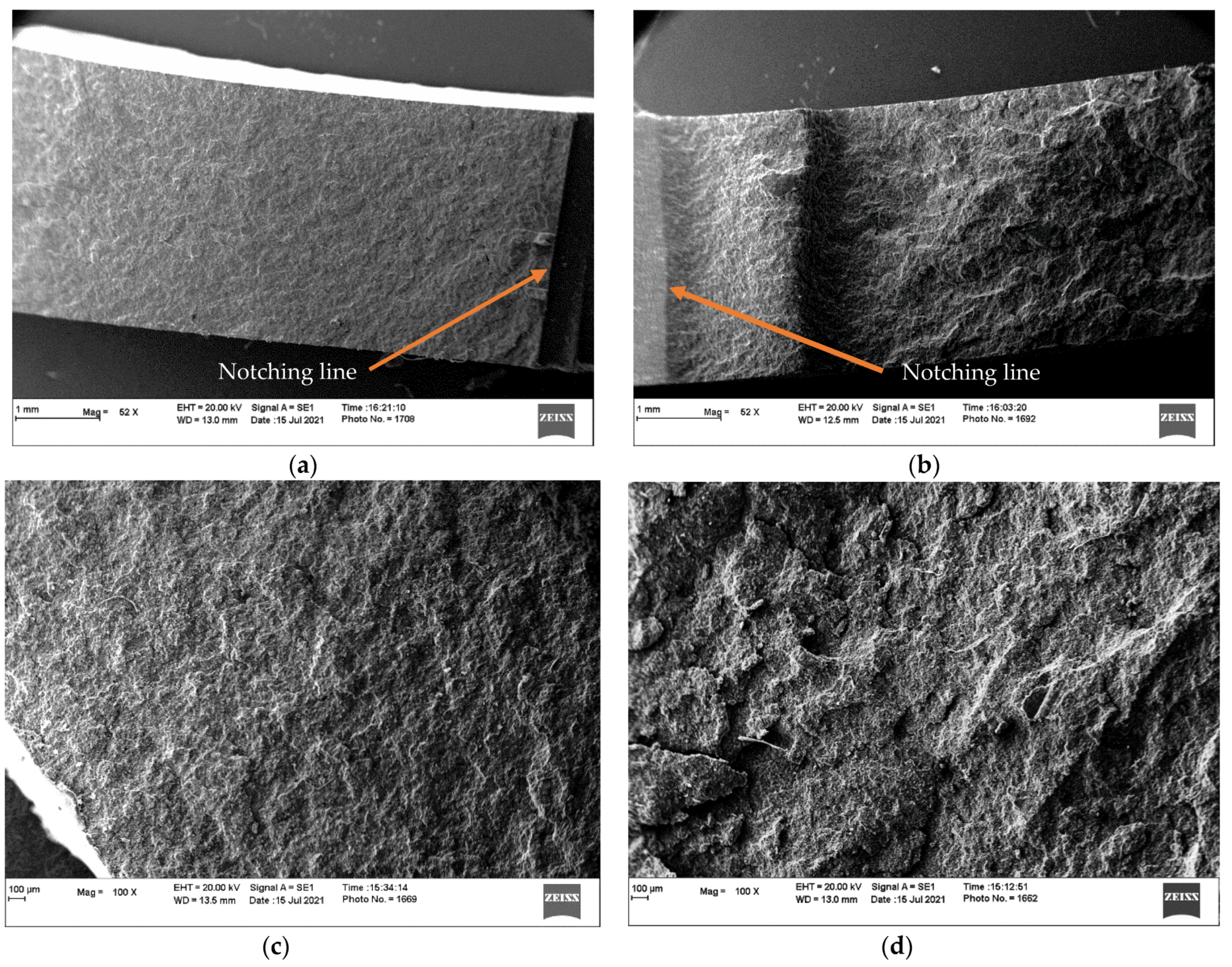
3 particles. For the same composite, unnotched impact strengths are much higher than notched impact strengths. The fracture surfaces of specimens after unnotched impact tests were observed to be much rougher than those after notched impact tests. The fracture surfaces of HPP filled with 30 and 50 wt.% CaCO3 particles after the notched and unnotched impact tests are shown in Figure 10. The relatively rougher surface indicated that more surface was created during the unnotched impact test, and more energy was required for the same surface properties for the same composites. The greater energy led to higher impact strength which was calculated by dividing the energy using the specimen cross-section area. This is one reason unnotched impact strength is much greater than notched impact strength.
For unnotched Izod impact test, inclusion of CaCO3 particles significantly decreased the impact strength (Table 1 and Figure 6). The initial stresses the specimen encountered at the moment of contacting with impact hammer is shown in Figure 7d and the fracture initiation started at the location contacting with the bottom sample holder. For composite with exposure of rigid particles on the surface, the fracture initiation point started at the interface between the rigid particle and the polymer phase due to a relatively weak bonding between the two incompatible surfaces (Figure 8b). Under such circumstance, fracture initiated without yielding of polymer phase, resulting in a lower fracture initiation energy than that of pure polymer specimen. The fracture initiation energy needed for the system is another reason the unnotched impact strength is much greater than notched impact strength. Once the fracture has been initiated, propagation continued under the external impact load toward the notching tip of the specimen (Figure 7e). Fracture propagation in CaCO3 particles filled HPP behaved the same as that in notched impact test and created relatively larger fracture surface area. However, the fracture initiation in unnotched impact test probably required a much higher magnitude of energy than that in fracture propagation and dominated the fracture process. Therefore, the unnotched impact strength of CaCO3 particles filled HPP is much lower than that of pure HPP.
During the fracture propagation, less amount of polymer was fractured in the fracture propagation path for a composite with a higher loading level of CaCO3 particles and a lower impact strength was obtained. Simultaneously, a composite with a higher CaCO3 particle loading level has more exposed particles on the surface and less amount of polymer to be fractured in the fracture initiation phase, resulting in a lower impact strength.

3.4. MFR

The MFR data and their standard deviations of all the composites are shown in Figure 11. The statistical analysis results of MFR data are also shown in Figure 11. The MFR of HPP after mixing and grinding was 14.7 g/10 min. Adding 10 wt.% CaCO3 particles in the composites did not significantly change the MFR. With 20, 30, 40, and 50 wt.% of CaCO3 particles, the MFRs of the composites decreased significantly to 13.2, 12.0, 10.5, and 10.3 g/10 min, respectively. Generally, with rigid particles in polymer composites, the flow of the composites is limited by restricting the molecular motion [35,36] and the MFR is lowered. At 10 wt.% loading level, the number of particles is not enough to limit most of the polymer flow during the test and the polymer molecular motion still dominates the flow behavior of the composites. When the loading of CaCO3 particles increased from 10 to 20, 30, and 40 wt.%, polymer molecules is resisted to move, and the resistance is in a linear relationship with CaCO3 particle loading. The linear relationship between the MFR (Y) of composite and CaCO3 particle loading level (X) is shown below:
Y = −12.9 X + 15.75 (R2 = 0.99)
When the CaCO3 particle loading level increased from 40 to 50 wt.%, the MFR stay at the same level (Figure 11). At the 40 wt.% loading level, the flow of the polymer phase is mainly restricted by the CaCO3 particles and the effect of the CaCO3 particles on melt flow dominates the composite behaviors. Large amount of CaCO3 particles was identified in the SEM micrographs (Figure 9e,f) which showed the dispersion of CaCO3 particles at 40 wt.% loading in HPP. Additional 10 wt.% CaCO3 particles did not change the composite MFR significantly.

4. Conclusions

At different loading levels, CaCO3 particles were mixed with a grade of HPP for manufacturing composites using an injection molding process. The mechanical behaviors of the composites were studied and analyzed in detail. The results indicated that tensile strengths decreased significantly with increasing loading levels of CaCO3 particles while the tensile and flexural moduli increased significantly with increasing filler loadings. Adding rigid CaCO3 particles changed the elastic deformation behaviors of the manufactured composites, resulting in higher moduli during tensile and flexural tests. The composite tensile properties changed linearly with increasing CaCO3 loadings. The mechanisms of changing HPP properties by including CaCO3 particles at different loadings were proposed for the tensile properties. The tensile strengths of the composites were mainly determined by the yielding strength of the polymer phase in the composites and the composite tensile strengths decreased linearly with the replacement of polymer phase in a linear relationship using 10, 20, 30, 40, and 50 wt.% of CaCO3 particles. The tensile strains at yielding also decreased linearly with increasing CaCO3 particles loading levels.
The notched Izod impact strength of the HPP was sustained by adding CaCO3 particles up to 40 wt.% while the unnotched impact strength decreased significantly with the addition of CaCO3 particles. Different deformation mechanisms during notched (fracture propagation) and unnotched (fracture initiation and propagation) impact tests were proposed to be the reason causing the different impact strengths. When CaCO3 particles were added into the composites, a different fracture surface was created during the Izod impact tests. During the notched Izod impact test, fracture propagated through a tortuous pathway along the interface between HPP and CaCO3 particles. The energy consumed for creating the rough surface of the composite can compensate the energy absorption capability loss of the polymer phase which was replaced by CaCO3 particles in the composites. The notched Izod impact strength of HPP can, therefore, be sustained with a loading level of CaCO3 particles up to 40 wt.%. For unnotched Izod impact tests, addition of CaCO3 particles significantly lowered the energy needed for fracture initiation due to the incompatibility between HPP and CaCO3 particles. The fracture initiation dominantly determined the impact strength of the composite for unnotched Izod impact tests and significantly lower unnotched impact strengths were obtained with increasing loading levels of CaCO3 particles.

Author Contributions

Conceptualization, Y.P.; methodology, Y.P., X.W. and M.M.; validation, M.M. and Y.P.; formal analysis, Y.P. and M.M.; investigation, M.M. and Y.P.; resources, Y.P. and B.V.; data curation, M.M. and Y.P.; writing—original draft preparation, Y.P. and M.M.; writing—review and editing, Y.P. and B.V.; visualization, Y.P.; supervision, Y.P.; project administration, Y.P.; funding acquisition, Y.P. All authors have read and agreed to the published version of the manuscript.

Funding

This research was funded by the USDA National Institute of Food and Agriculture and by the Alabama Agricultural Experiment Station.

Conflicts of Interest

The authors declare no conflict of interest. The funders had no role in the design of the study; in the collection, analyses, or interpretation of data; in the writing of the manuscript, or in the decision to publish the results.

References

  1. Shirvanimoghaddam, K.; Balaji, K.V.; Yadav, R.; Zabihi, O.; Ahmadi, M.; Adetunji, P.; Naebe, M. Balancing the toughness and strength in polypropylene composites. Compos. B-Eng. 2021, 223. [Google Scholar] [CrossRef]
  2. Jancar, J.; Dianselmo, A.; Dibenedetto, A.T.; Kucera, J. Failure Mechanics in Elastomer Toughened Polypropylene. Polymer 1993, 34, 1684–1694. [Google Scholar] [CrossRef]
  3. Eiras, D.; Pessan, L.A. Mechanical Properties of Polypropylene/Calcium Carbonate Nanocomposites. Mater. Res.-Ibero-Am. J. 2009, 12, 517–522. [Google Scholar] [CrossRef] [Green Version]
  4. Deblieck, R.; Remerie, K.; Van den Fonteyne, W.; Boerakker, M. A Morphology-Based Model to Describe the Low-Temperature Impact Behaviour of Rubber-Toughened Polypropylene. Polymers 2021, 13, 2218. [Google Scholar] [CrossRef] [PubMed]
  5. Maddah, H.A. Polypropylen as a promising plastic: A review. Am. J. Polym. Sci. 2016, 6, 1–11. [Google Scholar] [CrossRef]
  6. Goldman, A.Y.; Copsey, C.J. Polypropylene toughened with calcium carbonate mineral filler. Mater. Res. Innov. 2000, 3, 302–307. [Google Scholar] [CrossRef]
  7. Chan, C.M.; Wu, J.S.; Li, J.X.; Cheung, Y.K. Polypropylene/calcium carbonate nanocomposites. Polymer 2002, 43, 2981–2992. [Google Scholar] [CrossRef]
  8. Chafidz, A.; Kaavessina, M.; Al-Zahrani, S.; Al-Otaibi, M.N. Rheological and mechanical properties of polypropylene/calcium carbonate nanocomposites prepared from masterbatch. J. Thermoplast. Compos. 2016, 29, 593–622. [Google Scholar] [CrossRef]
  9. Liang, J.Z.; Li, R.K.Y. Rubber toughening in polypropylene: A review. J. Appl. Polym. Sci. 2000, 77, 409–417. [Google Scholar] [CrossRef]
  10. Jang, B.Z. Rubber-Toughening in Polypropylene. J. Appl. Polym. Sci. 1985, 30, 2485–2504. [Google Scholar] [CrossRef]
  11. Bucknall, C.B.; Page, C.J. Rubber-Toughening of Plastics Part 6 Effects of Rubber Particles on the Kinetics of Creep in Polypropylene. J. Mater. Sci 1982, 17, 808–816. [Google Scholar] [CrossRef]
  12. Wang, X.; Hu, S.; Guo, Y.; Li, G.Q.; Xu, R.W. Toughened High-Flow Polypropylene with Polyolefin-Based Elastomers. Polymers 2019, 11, 1976. [Google Scholar] [CrossRef] [Green Version]
  13. Lin, Y.; Chen, H.B.; Chan, C.M.; Wu, J.S. The toughening mechanism of polypropylene/calcium carbonate nanocomposites. Polymer 2010, 51, 3277–3284. [Google Scholar] [CrossRef]
  14. Shi, L.; Xiao, J.M. The toughening mechanism of rubber particles in polypropylene composite. IOP Conf. Ser.-Mat. Sci 2017, 164. [Google Scholar] [CrossRef] [Green Version]
  15. Zuiderduin, W.C.J.; Westzaan, C.; Huetink, J.; Gaymans, R.J. Toughening of polypropylene with calcium carbonate particles. Polymer 2003, 44, 261–275. [Google Scholar] [CrossRef]
  16. Chen, F.; Shangguan, Y.G.; Jiang, Y.S.; Qiu, B.W.; Luo, G.H.; Zheng, Q. Toughening with little rigidity loss and mechanism for modified polypropylene by polymer particles with core-shell structure. Polymer 2015, 65, 81–92. [Google Scholar] [CrossRef]
  17. Zhang, L.; Li, C.Z.; Huang, R. Toughness mechanism in polypropylene composites: Polypropylene toughened with elastomer and calcium carbonate. J. Polym. Sci. Pol. Phys. 2004, 42, 1656–1662. [Google Scholar] [CrossRef]
  18. Bartczak, Z.; Argon, A.S.; Cohen, R.E.; Weinberg, M. Toughness mechanism in semi-crystalline polymer blends: II. High-density polyethylene toughened with calcium carbonate filler particles. Polymer 1999, 40, 2347–2365. [Google Scholar] [CrossRef]
  19. Fu, S.Y.; Feng, X.Q.; Lauke, B.; Mai, Y.W. Effects of particle size, particle/matrix interface adhesion and particle loading on mechanical properties of particulate-polymer composites. Compos. B-Eng. 2008, 39, 933–961. [Google Scholar] [CrossRef]
  20. Zebarjad, S.M.; Tahani, M.; Sajjadi, S.A. Influence of filler particles on deformation and fracture mechanism of isotactic polypropylene. J. Mater. Process Tech. 2004, 155, 1459–1464. [Google Scholar] [CrossRef]
  21. Badran, B.M.; Galeski, A.; Kryszewski, M. High-Density Polyethylene Filled with Modified Chalk. J. Appl. Polym. Sci. 1982, 27, 3669–3681. [Google Scholar] [CrossRef]
  22. Liu, Z.H.; Kwok, K.W.; Li, R.K.Y.; Choy, C.L. Effects of coupling agent and morphology on the impact strength of high density polyethylene/CaCO3 composites. Polymer 2002, 43, 2501–2506. [Google Scholar] [CrossRef]
  23. Wang, Y.; Lu, J.; Wang, G.H. Toughening and reinforcement of HDPE/CaCO3 blends by interfacial modification interfacial interaction. J. Appl. Polym. Sci. 1997, 64, 1275–1281. [Google Scholar] [CrossRef]
  24. Yue, C.Y.; Cheung, W.L. Discriminating between Strength-Based and Fracture-Based Approaches in Debonding in Glass Fiber-Reinforced Polypropylene Composite. J. Mater. Sci. Lett. 1991, 10, 1335–1337. [Google Scholar] [CrossRef]
  25. Ramsteiner, F.; Theysohn, R. On the Tensile Behavior of Filled Composites. Composites 1984, 15, 121–128. [Google Scholar] [CrossRef]
  26. Kim, G.M.; Michler, G.H. Micromechanical deformation processes in toughened and particle filled semicrystalline polymers. Part 2: Model representation for micromechanical deformation processes. Polymer 1998, 39, 5699–5703. [Google Scholar] [CrossRef]
  27. Kim, G.M.; Michler, G.H. Micromechanical deformation processes in toughened and particle-filled semicrystalline polymers: Part 1. Characterization of deformation processes in dependence on phase morphology. Polymer 1998, 39, 5689–5697. [Google Scholar] [CrossRef]
  28. Thio, Y.S.; Argon, A.S.; Cohen, R.E.; Weinberg, M. Toughening of isotactic polypropylene with CaCO3 particles. Polymer 2002, 43, 3661–3674. [Google Scholar] [CrossRef]
  29. Zhang, Q.X.; Yu, Z.Z.; Xie, X.L.; Mai, Y.W. Crystallization and impact energy of polypropylene/CaCO3 nanocomposites with nonionic modifier. Polymer 2004, 45, 5985–5994. [Google Scholar] [CrossRef]
  30. Chen, N.; Wan, C.Y.; Zhang, Y.; Zhang, Y.X. Effect of nano-CaCO3 on mechanical properties of PVC and PVC/blendex blend. Polym. Test. 2004, 23, 169–174. [Google Scholar] [CrossRef]
  31. Allard, R.C.; Vukhanh, T.; Chalifoux, J.P. Fatigue Crack-Propagation in Mica-Filled Polyolefins. Polym Compos. 1989, 10, 62–68. [Google Scholar] [CrossRef]
  32. Yang, K.; Yang, Q.; Li, G.X.; Sun, Y.J.; Feng, D.C. Morphology and mechanical properties of polypropylene/calcium carbonate nanocomposites. Mater. Lett. 2006, 60, 805–809. [Google Scholar] [CrossRef]
  33. Maiti, S.N.; Mahapatro, P.K. Mechanical-Properties of i-PP/CaCO3 Composites. J. Appl. Polym. Sci. 1991, 42, 3101–3110. [Google Scholar] [CrossRef]
  34. Peng, Y.C.; Gallegos, S.A.; Gardner, D.J.; Han, Y.; Cai, Z.Y. Maleic anhydride polypropylene modified cellulose nanofibril polypropylene nanocomposites with enhanced impact strength. Polym. Compos. 2016, 37, 782–793. [Google Scholar] [CrossRef]
  35. Jam, N.J.; Behravesh, A.H. Flow Behavior of HDPE-Fine wood particles composites. J. Thermoplast. Compos. 2007, 20, 439–451. [Google Scholar] [CrossRef]
  36. Shumigin, D.; Tarasova, E.; Krumme, A.; Meier, P. Rheological and Mechanical Properties of Poly(lactic) Acid/Cellulose and LDPE/Cellulose Composites. Mater. Sci. 2011, 17, 32–37. [Google Scholar] [CrossRef] [Green Version]
Figure 1. SEM micrographs of CaCO3 particles at different magnifications (a) 5000× and (b) 2000×.
Jcs 05 00302 g001
Figure 2. The tensile properties of the HPP and CaCO3 filled HPP composites (a) tensile modulus of elasticity (MOE) and strength and (b) tensile strain at yield.
Jcs 05 00302 g002
Figure 3. Schematic representation of the CaCO3 fille HPP composites at equilibrium and under tensile load: (a) residual stress in CaCO3 particles, (b) initial stage of elastic deformation zone, (c) the end point of the elastic deformation zone, and (d) the yielding point of the composites.
Jcs 05 00302 g003
Figure 4. A set of representative stress-strain curves for the composites.
Jcs 05 00302 g004
Figure 5. The flexural properties of the HPP and CaCO3 filled HPP composites.
Jcs 05 00302 g005
Figure 6. The impact strengths of HPP and CaCO3 filled HPP composites.
Jcs 05 00302 g006
Figure 7. A schematic demonstration of specimen failure in notched Izod impact test (ac) and unnotched Izod impact test (d,e).
Jcs 05 00302 g007
Figure 8. A schematic description of fracture propagation in notched Izod impact test (a) and fracture initiation in unnotched Izod impact test (b).
Jcs 05 00302 g008
Figure 9. SEM micrographs of HPP: (a,b), 30 wt.% CaCO3 filled HPP: (c,d), and 40 wt.% CaCO3 filled HPP (e,f).
Jcs 05 00302 g009
Figure 10. The comparison of the fracture surfaces for specimens after notched and unnotched impact tests: (a,b) notched and unnotched impact testing specimens for HPP filled with 30 wt.% CaCO3, (c,d) notched and unnotched impact testing specimens for HPP filled with 50 wt.% CaCO3.
Jcs 05 00302 g010
Figure 11. The MFR of HPP and CaCO3 particles filled HPP. The letters A, B, C, and D represent the significant levels in statistical analysis. The values with different letters are significantly different.
Jcs 05 00302 g011
Table 1. The mechanical properties of CaCO3 particles filled HPP.
CompositeTensile PropertiesFlexural PropertiesImpact Strength (kJ/m2)
MOE (GPa)Strength (MPa)Strain (%)MOE (GPa)Strength (MPa) 3NotchedUnnotched
HPP (0%)1.54 ± 0.05 1E 232.1 ± 0.7F10.7 ± 0.3A1.50 ± 0.02E50.0 ± 0.3C1.66 ± 0.15A/B50.3 ± 8.3A
10% CaCO31.85 ± 0.06D30.4 ± 0.5E7.4 ± 0.4B1.98 ± 0.08D57.1 ± 1.3A1.62 ± 0.12B30.1 ± 3.5B
20% CaCO32.02 ± 0.04C29.0 ± 0.3D7.0 ± 0.3B1.92 ± 0.13D53.3 ± 2.0B1.75 ± 0.10A/B24.5 ± 4.6C
30% CaCO32.09 ± 0.13C26.1 ± 0.7C5.7 ± 0.3C2.37 ± 0.08C53.5 ± 1.4B1.81 ± 0.14A27.3 ± 4.7B/C
40% CaCO32.70 ± 0.12B23.3 ± 0.9B3.9 ± 0.3D2.75 ± 0.09B49.5 ± 1.1C1.77 ± 0.32A/B20.1 ± 3.5D
50% CaCO32.99 ± 0.11A20.4 ± 0.5A2.6 ± 0.3E3.26 ± 0.37A43.7 ± 3.3D1.33 ± 0.15C5.67 ± 0.5E
1 Standard deviation. 2 The letters A, B, C, D, E, and F represent the significant levels in statistical analysis. The values with different letters are significantly different. 3 The strength for flexural properties is the stress at 5% strain since no specimens broke.
Publisher’s Note: MDPI stays neutral with regard to jurisdictional claims in published maps and institutional affiliations.

