Article

Void Content Reduction in 3D Printed Glass Fiber-Reinforced Polymer Composites through Temperature and Pressure Consolidation

by
Dakota R. Hetrick
1,
Seyed Hamid Reza Sanei
1,* and
Omar Ashour
2
1
Department of Mechanical Engineering, Penn State Erie, The Behrend College, Erie, PA 16563, USA
2
Department of Industrial Engineering, Penn State Erie, The Behrend College, Erie, PA 16563, USA
*
Author to whom correspondence should be addressed.
J. Compos. Sci. 2022, 6(5), 128; https://0-doi-org.brum.beds.ac.uk/10.3390/jcs6050128
Submission received: 15 April 2022 / Revised: 22 April 2022 / Accepted: 26 April 2022 / Published: 28 April 2022
(This article belongs to the Special Issue Additive Manufacturing of Composites and Nanocomposites)

Abstract

:
To improve the properties of additively manufactured parts to be used in high-end applications, intrinsic defects occurring during the printing process need to be minimized. Defects such as void can significantly degrade the mechanical properties of the resulted parts. The presence of void is more evident in composite printed parts due to the inhomogeneity of the specimen. In this study, composite rectangular coupons printed with a Markforged Mark Two printer were manufactured with different fiber orientations and stacking sequences. A void content reduction/consolidation process, consisting of applying pressure at different temperature levels, was developed and implemented to remove the voids in form of air bubbles trapped in the specimen. A two-part mold with female and male components with the same dimensions as the rectangular specimen was designed and machined to be used in a hot press process. The success of the approach was evaluated by calculating the density of the specimen pre- and post-consolidation. The void content reduction results were highly dependent on fiber orientation; however, the density increased for all tested specimens, confirming the reduction in porosity.

1. Introduction

Additive manufacturing (AM) processes produce three-dimensional (3D) complex geometries from computer-aided design (CAD) files. The resulting geometries from AM are usually near shape and do not require post-processing. AM is an umbrella term that includes: Fused Deposition Modeling (FDM) from polymer filaments, Selective Laser Sintering (SLS) from metal or polymer powders, Laminated Object Manufacturing (LOM) from polymer laminations, and Stereolithography (SLA) of a photopolymer liquid [1,2,3,4]. To produce 3D geometries, FDM deposits successive layers of thermoplastic filament via extrusion [5]. FDM is commonly used because it results in low waste, is easy to use, and is relatively cheap [5,6,7]. FDM printed parts lack the needed strength for these parts to be used in industrial applications. Combining the advantages of AM with directional properties of composites has large untapped potentials [8,9,10,11]. Thus, reinforcement materials such as nanomaterials, particles, and fibers are usually added to enhance the mechanical properties, and improve the performance and functionality of the 3D printed parts [12,13,14,15,16,17]. The current research studies have been focused on evaluating the mechanical properties of the AM composite parts [13,18,19,20]. Moreover, other studies have been investigating the modification and optimization of the 3D printing process parameters to improve the properties of the composite parts [5,21,22,23,24,25]; however, few studies have attempted to enhance the properties after the 3D printing process (post-processing).
Composite properties are highly function of their microstructures [26,27]. AM parts have several intrinsic shortcomings in their underlying microstructures compared to their compression-molded counterparts, such as waviness of fibers due to lack of tension, poor interlaminar adhesion due to the additive nature of manufacturing, and porosity also referred to as void content [9,16,17,22,28]. The presence of void is not unique to AM parts and it is a well-studied defect in conventional composite material which has been shown to significantly degrade the mechanical properties of the produced parts [29,30,31]. Research suggests that void formation is induced by the 3D printing process [10,32,33]. For example, voids have been associated with thermal stresses and improper impregnation [34], and they have been found in distinctive internal areas of the 3D-printed parts [35,36]. The impact of voids on additively manufactured composite parts is more pronounced compared to additively manufactured polymers because they tend to form between the fiber filamentsVoids can appear within and between layers from submicron level to macro-scale. The following types of voids contribute to lowering the structural integrity of the AM parts: (a) micro voids, which form within fiber and matrix filament before printing, (b) meso voids, which form between fiber bundles after printing within a layer as fiber bundles are not circular after deposition, and (c) macro voids, which form between adjacent layers. Several studies have investigated the mechanical and structural properties, such as tensile, bending, and impact properties, of continuous fiber-reinforced thermoplastic composites printed by FDM [12,13,15,16,17,18,37]. Others have studied the impact of void content characteristics, quantity, and distribution using 2D imaging and 3D visualization techniques such as scanning electron microscopy and X-ray micro-computed tomography (micro-CT) [38,39,40,41,42,43,44,45,46,47,48]. Moreover, the effect of nozzle geometry on void formation is studied in [22], and Ning et al. have shown the presence of void in the form of gas bubbles, interbead voids, and fiber pull out [49]. In addition to degrading the mechanical properties of AM composite parts, porosity facilitates moisture absorption during service, hence further degrading the structural integrity of the part.
Unlike conventional composite manufacturing processes, the AM process does not involve applying considerable pressure during the printing process, thus voids are more likely to occur. Post-processing operations such as applying pressure at elevated temperatures could be used to remove the air pockets that formed during AM. Investigating the impact of post-processing void removal could potentially eliminate a common problem in 3D printing processes. In this work, a novel post-processing void content reduction process in 3D printed glass fiber-reinforced polymer composites using pressure at elevated temperatures is developed and investigated. To perform the process, a two-part mold was designed, machined, and used in a hot press. The bottom part of the mold consists of a rectangular slot that is slightly larger than the specimen. The top part of the mold represents the male piece that is used to apply the pressure in the hot press. The void reduction/consolidation process consists of a combination of pressure/temperature profiles. The consolidation procedure is developed and optimized to minimize the flashing and burning of the specimen while achieving the desirable flow of material to remove voids. The success of the consolidation process is evaluated by calculating the specimen’s density pre- and post-processing. The impact fiber direction and intralayer adhesion, different fiber orientation, and stacking sequence are studied. The results show that post-processing reduces the void content; this is evident from the reduction of the specimen density for all the tested configurations.
This paper is organized as follows: Section 2 describes the post-processing procedure, material, and the specimens used in the experiment. Section 3 presents the results of porosity measurement, and discusses and interprets the experiment results. Section 4 provides the main conclusions achieved along with the suggested future work.

2. Specimen Manufacturing

2.1. Printing Process and Materials

The raw materials used in manufacturing the specimens were a matrix material filament and a fiber reinforcement filament. The matrix material used in the study was chopped carbon fiber-reinforced Nylon referred to as Onyx. This material is proprietary to Markforged, Inc., thus the detail of the type of Nylon used and the discontinuous fiber reinforcement are unknown except what the company provided including basic material properties [50]. The reinforcement material could be either carbon fiber, Kevlar, fiberglass, or high-strength high-temperature (HSHT) fiberglass. This study used fiberglass reinforcement due to the material’s cost-effectiveness given the high tensile strength. The fiber reinforcement filament was comprised of multiple individual continuous fibers held together via a binder agent. The composition of the binder agent and the specific type of fiberglass are also unknown due to the materials being proprietary. The general printing process of the Markforged® Mark Two printer is similar to the generic FDM printing process. The printer uses a dual nozzle print head; one nozzle for the matrix material and one for the fiber reinforcement. The matrix material was printed using the same process as FDM. The fiber reinforcement nozzle had a large flat end for ironing fiber filaments after printing. The fiber was extruded through a heated nozzle that melted the binder agent holding the fiber strands in the fiber filament. Fiber reinforcement was continuous in each layer, but fibers were cut moving from one layer to another. Due to the lack of tension in the process, waviness was observed in the resulted specimens.

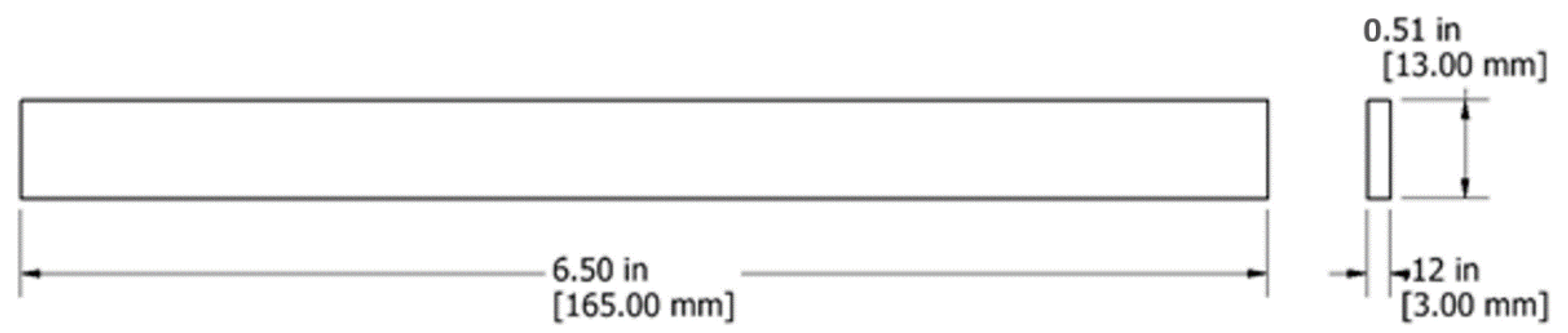
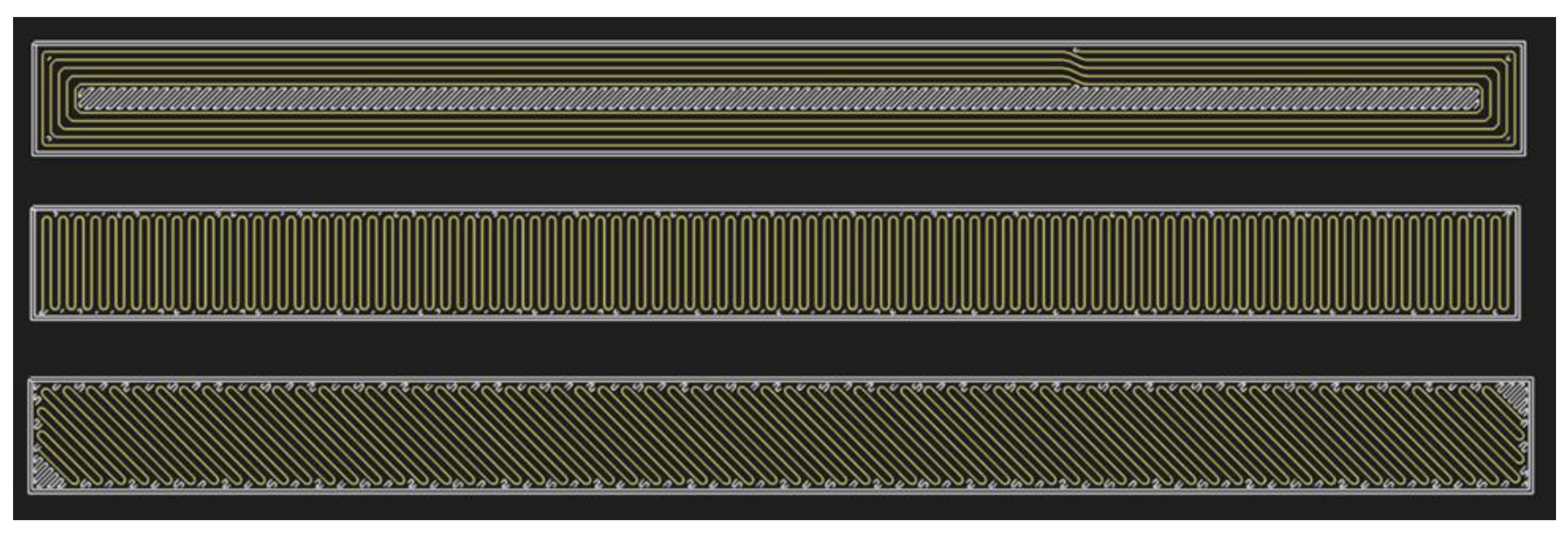
2.2. Specimen and Fiber Orientation

A total of 32 rectangular tensile specimens were printed for seven different configurations. The dimensions of the specimen are shown in Figure 1. For this study, four specimens were printed for each configuration. Fiber volume fraction, the number of layers, and print parameters were identical for all specimens while the configuration of fiber orientation and stacking sequences were altered. In the Eiger slicing software (Markforged® Mark Two software), the orientation of the fiber reinforcement can be varied with 0.01-degree resolution. Fibers can be printed either in unidirectional or concentric patterns. An example of fiber orientations can be seen in Figure 2. In this work, two stacking sequences were studied, i.e., consolidated and alternating. The consolidated stacking sequence does not have any matrix layers between the fiber layers. The alternating stacking sequence alternates a matrix layer between the fiber layers. Overall, the fiber orientation configurations were five concentric rings, 90°, and ±45°. The unidirectional 0° orientation was not used because it was closely similar to the five concentric rings configuration. There were consolidated and alternating stacking sequences for each fiber orientation configuration.

2.3. Measurements

The consolidation process involved measuring the mass and volume of all specimens pre- and post-processing. The mass of the specimen was measured via an analytical balance with 0.0001 g accuracy. The width, thickness, and length of the specimen were measured using a digital caliper with 0.001 mm accuracy. Due to the nature of the consolidation process, there is bound to be flashing to some degree. Before the post-processing measurements were taken, the flashing was trimmed off with a razor knife. Extreme care was taken to ensure that only the flashing material was trimmed off and that the specimen was left intact. The volume of the specimen was calculated using the width, thickness, and length measurements. To achieve accurate measurements of the thickness and the width over the length of the specimen, the thickness and width of the specimen were determined by calculating the mean of five measurements across the length of the specimen.
The theoretical and actual density values were used to calculate the void content pre- and post-processing. The theoretical density was obtained by the Eiger software. The software returned the matrix and fiber volume, and the total mass of the final part. The actual density was calculated by dividing the measured mass by the measured volume. The actual density was measured both pre- and post-processing to observe the change in void content. Finally, the void content was measured by taking the absolute difference between the theoretical and actual density values then dividing by the theoretical density adopted from ASTM D2734.

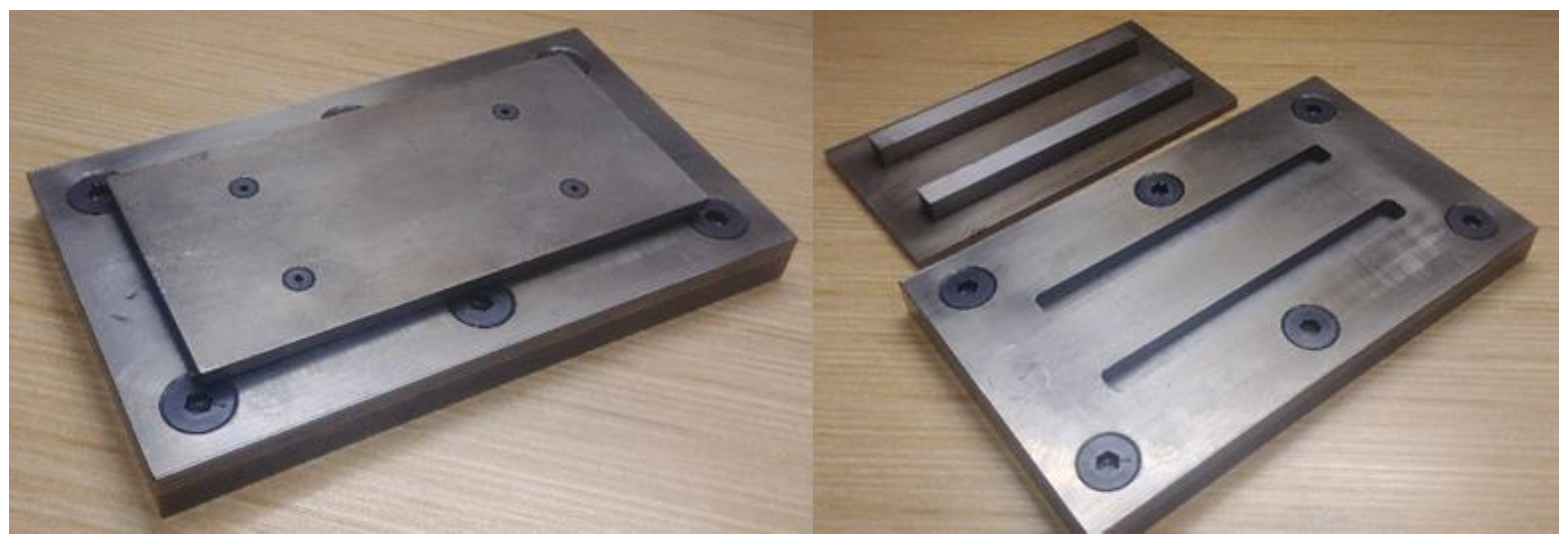
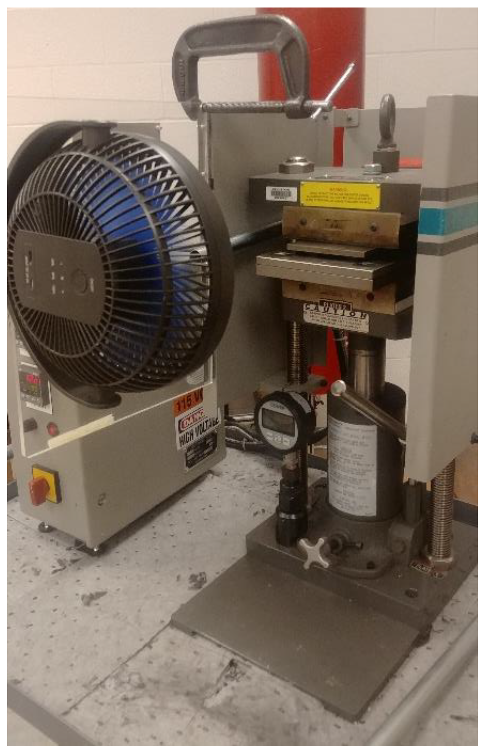
2.4. Consolidation Processing

The consolidation process consisted of three stages: Heating stage, consolidation stage, and cooling stage. All three stages were conducted under pressure and various temperature levels. For the consolidation process to be completed, a mold was designed and machined as shown in Figure 3, and a hot press, shown in Figure 4, was used to apply the heat and pressure required for post-processing. An electrical fan was utilized to help maintain a constant temperature as well as cool the mold while still under pressure.
To calibrate the consolidation process, the pressure and temperature levels were varied to achieve an optimized procedure. Initially, a temperature of 250 °C was used and the pressure levels were varied (27 psi, 189 psi, and 189 psi). The heating stage did not need much adjustment, and the temperature did not fluctuate around the set point. However, as the pressure was controlled manually, the pressure fluctuated between 27 psi to 37 psi for the lower pressure set point.
The pressure and temperature levels were higher than needed for the consolidation stage, therefore they both were lowered. The appropriate temperature was determined by starting at 150 °C and gradually increased by 25 °C increments until flashing was reduced to a minimal amount. A temperature of 200 °C was determined as appropriate and then the pressure levels were varied. The pressure range initially used was 150 psi to 180 psi but the visible voids on the bottom of the specimens did not disappear. Thus, the second pressure range used was 210 psi to 230 psi. This pressure range eliminated the visible voids on the bottom of the specimen, however, the increased pressure also resulted in increased flashing. The temperature was reduced slightly to 195 °C. The final temperature and pressure that was used for the consolidation stage was 195 °C with a pressure range of 210 psi to 230 psi. This pressure and temperature were held for 10 min to provide the consolidation stage enough time to sufficiently remove the voids. It must be noted that during the printing process, the fiber nozzle temperature was 252 °C and the plastic nozzle temperature was set to 277 °C. During the consolidation process, the temperature of 200 °C was applied. This temperature was determined after evaluating several temperature-pressure profiles.
Finally, the hot press was cooled to 150 °C and the holding pressure was kept at the consolidation pressure range. The temperature was selected to be 150 °C to make the material flexible enough without reaching the glass transition temperature range. The mold was removed from the press at 150 °C and then allowed to cool to 50 °C under no pressure. The specimens were then removed from the mold to cool at room temperature.

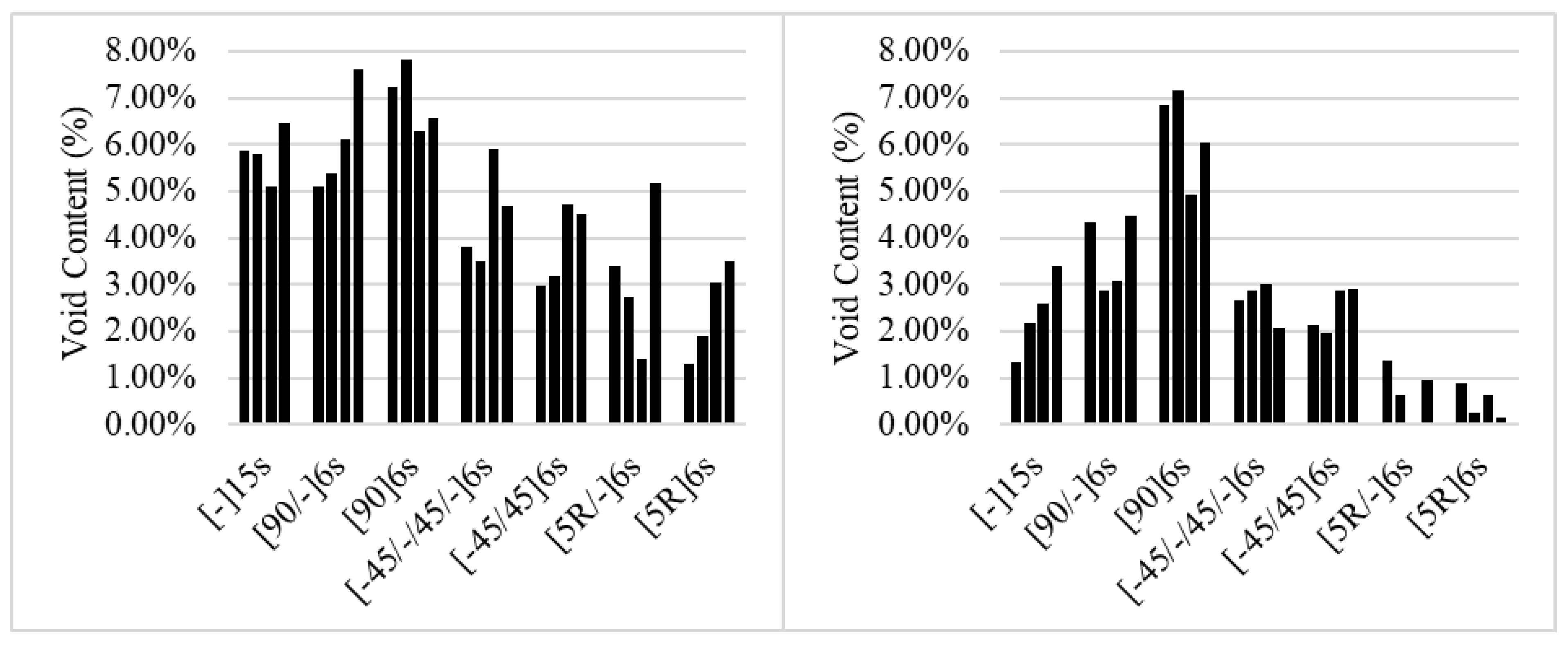
3. Porosity Measurements

As expected for an additively manufactured specimen, there is a large percentage of porosity within the specimen both pre- and post-processing. To evaluate the void content, the mass and geometry of the specimens were measured prior to and after the void reduction process. To estimate the void content in the specimens, the calculated and theoretical density values were compared. In addition to the void content of each specimen, the coefficient of variation was calculated to evaluate the consistency of results.
The void content reductions were calculated and are shown in Table 1. Overall, the void removal process was successful in reducing the void content; among all specimens, the void content was reduced 2%. Table 2 shows the coefficient of variation for the void content of specimen prior to and after the void removal process. It can be seen that there is larger variation after the removal process.
The void content was reduced for each specimen, although, as expected, the amount of variation between the specimens was rather high. This can stem from a few sources. One reason might be that high amounts of variation are intrinsic to 3D printing, one of the many hurdles that 3D printing must overcome to become a widely used manufacturing method. The other source could be due to the pressure being applied manually. This fluctuation could have caused variable reduction in void from one specimen to another. If the pressure fluctuated on the high end of the pressure range, then there would be a higher reduction in void content. Figure 5 shows the comparison of void content between specimens with different stacking sequence. It can be seen that the specimens with no continuous fiber showed the largest reduction in void content. The analysis of variation in void content result showed that not only did the consolidation process not lower the variability, it instead increased the variability in the results due to the added process.

4. Conclusions

Additively manufactured specimens have large porosity degrading the overall mechanical properties. The porosity can appear between infills within a layer or between adjacent layer. The porosity would be more pronounced in composite specimens as continuous fiber strands will not geometrically fit perfectly adjacent to each other and an unavoidable gap will form between fiber layers; unlike conventional composites, there is no thermoset resin to run through and fill the gaps. In this study, as there is no standard yet established for void removal, an experimental trial and error was pursued to find the optimized temperature and pressure for void removal of a glass fiber-reinforced Onyx specimen. A two-part mold was designed to encompass the specimen in the female bottom part of the mold with the male top part of the mold applying pressure. Flashing of the material outside the mold was a dominant challenge in the consolidation process. Flashing was minimized after the optimized pressure and temperature range was determined. Mass and volume measurement prior to and post consolidation process returned the void content reduction. The results showed that the process was successful in achieving its objective in reduction of porosity in the specimens. On average, 2% porosity was removed from the specimens. Specimens with different stacking sequences were manufactured and processed to evaluate the effect of fiber orientation. It was shown that specimens with no continuous fiber had the largest void content reduction after the process, confirming the hypothesis that gaps are formed between fiber strands and they can be difficult to remove even with a consolidation process. In addition to the density measurement evaluation presented in this paper, mechanical testing for a pre- and post-consolidation process can serve as another assessment tool for the success of the experiment.

Author Contributions

Conceptualization, D.R.H.; methodology, S.H.R.S.; software, O.A.; validation, D.R.H., S.H.R.S. and O.A.; formal analysis, D.R.H.; investigation, O.A.; resources, S.H.R.S.; data curation, D.R.H.; writing—original draft preparation, D.R.H.; writing—review and editing, S.H.R.S.; visualization, D.R.H.; supervision, O.A.; project administration, S.H.R.S.; funding acquisition, D.R.H. All authors have read and agreed to the published version of the manuscript.

Funding

This research received no external funding.

Conflicts of Interest

The authors declare no conflict of interest.

References

  1. Kotlinski, J. Mechanical properties of commercial rapid prototyping materials. Rapid Prototyp. J. 2014, 20, 499–510. [Google Scholar] [CrossRef]
  2. Wang, Q.; Mitsumura, N.; Chen, Q.; Sarkar, A.; Kurokawa, H.; Sekiguchi, K.; Sugiyama, K. Investigation of condensation reaction during phenol liquefaction of waste woody materials. Int. J. Sustain. Dev. Plan. 2014, 9, 658–668. [Google Scholar] [CrossRef]
  3. Dizon, J.R.C.; Espera, A.H.; Chen, Q.; Advincula, R.C. Mechanical characterization of 3D-printed polymers. Addit. Manuf. 2018, 20, 44–67. [Google Scholar] [CrossRef]
  4. Melenka, G.W.; Cheung, B.K.O.O.; Schofield, J.S.; Dawson, M.R.; Carey, J.P. Evaluation and prediction of the tensile properties of continuous fiber-reinforced 3D printed structures. Compos. Struct. 2016, 153, 866–875. [Google Scholar] [CrossRef]
  5. Caminero, M.A.; Chacón, J.M.; García-Moreno, I.; Rodríguez, G.P. Impact damage resistance of 3D printed continuous fibre reinforced thermoplastic composites using fused deposition modelling. Compos. Part B Eng. 2018, 148, 93–103. [Google Scholar] [CrossRef]
  6. Chacón, J.M.; Caminero, M.A.; García-Plaza, E.; Núñez, P.J. Additive manufacturing of PLA structures using fused deposition modelling: Effect of process parameters on mechanical properties and their optimal selection. Mater. Des. 2017, 124, 143–157. [Google Scholar] [CrossRef]
  7. Dickson, A.N.; Barry, J.N.; McDonnell, K.A.; Dowling, D.P. Fabrication of continuous carbon, glass and Kevlar fibre reinforced polymer composites using additive manufacturing. Addit. Manuf. 2017, 16, 146–152. [Google Scholar] [CrossRef]
  8. Kabir, S.M.F.; Mathur, K.; Seyam, A.F.M. A critical review on 3D printed continuous fiber-reinforced composites: History, mechanism, materials and properties. Compos. Struct. 2020, 232, 111476. [Google Scholar] [CrossRef]
  9. Brenken, B.; Barocio, E.; Favaloro, A.; Kunc, V.; Pipes, R.B. Fused filament fabrication of fiber-reinforced polymers: A review. Addit. Manuf. 2018, 21, 1–16. [Google Scholar] [CrossRef]
  10. Mohammadizadeh, M.; Imeri, A.; Fidan, I.; Elkelany, M. 3D printed fiber reinforced polymer composites—Structural analysis. Compos. Part B Eng. 2019, 175, 107112. [Google Scholar] [CrossRef]
  11. van de Werken, N.; Tekinalp, H.; Khanbolouki, P.; Ozcan, S.; Williams, A.; Tehrani, M. Additively manufactured carbon fiber-reinforced composites: State of the art and perspective. Addit. Manuf. 2020, 31, 100962. [Google Scholar] [CrossRef]
  12. Wang, X.; Jiang, M.; Zhou, Z.; Gou, J.; Hui, D. 3D printing of polymer matrix composites: A review and prospective. Compos. Part B Eng. 2017, 110, 442–458. [Google Scholar] [CrossRef]
  13. Sanei, S.H.R.; Popescu, D. 3D-Printed Carbon Fiber Reinforced Polymer Composites: A Systematic Review. J. Compos. Sci. 2020, 4, 98. [Google Scholar] [CrossRef]
  14. Matsuzaki, R.; Ueda, M.; Namiki, M.; Jeong, T.K.; Asahara, H.; Horiguchi, K.; Nakamura, T.; Todoroki, A.; Hirano, Y. Three-dimensional printing of continuous-fiber composites by in-nozzle impregnation. Sci. Rep. 2016, 6, 23058. [Google Scholar] [CrossRef]
  15. Hofstätter, T.; Pedersen, D.B.; Tosello, G.; Hansen, H.N. State-of-the-art of fiber-reinforced polymers in additive manufacturing technologies. J. Reinf. Plast. Compos. 2017, 36, 1061–1073. [Google Scholar] [CrossRef] [Green Version]
  16. Hetrick, D.; Sanei, S.H.R.; Bakis, C.E.; Ashour, O. Evaluating the Effect of Variable Fiber Content on Mechanical Properties of Additively Manufactured Continuous Carbon Fiber Composites. J. Reinf. Plast. Compos. 2020, 40, 365–377. [Google Scholar] [CrossRef]
  17. Hetrick, D.R.; Sanei, S.H.R.; Ashour, O.; Bakis, C.E. Charpy impact energy absorption of 3D printed continuous Kevlar reinforced composites. J. Compos. Mater. 2021, 55, 1705–1713. [Google Scholar] [CrossRef]
  18. Sanei, S.H.R.; Lash, Z.; Servey, J.; Gardone, F.; Nikhare, C.P. Mechanical properties of 3D printed fiber reinforced thermoplastic. In Proceedings of the ASME International Mechanical Engineering Congress and Exposition, Salt Lake City, UT, USA, 11–14 November 2019; Volume 12. [Google Scholar]
  19. Mohammadizadeh, M.; Gupta, A.; Fidan, I. Mechanical benchmarking of additively manufactured continuous and short carbon fiber reinforced nylon. J. Compos. Mater. 2021, 55, 3629–3638. [Google Scholar] [CrossRef]
  20. Fidan, I.; Imeri, A.; Gupta, A.; Hasanov, S.; Nasirov, A.; Elliott, A.; Alifui-Segbaya, F.; Nanami, N. The trends and challenges of fiber reinforced additive manufacturing. Int. J. Adv. Manuf. Technol. 2019, 102, 1801–1818. [Google Scholar] [CrossRef]
  21. Araya-Calvo, M.; López-Gómez, I.; Chamberlain-Simon, N.; León-Salazar, J.L.; Guillén-Girón, T.; Corrales-Cordero, J.S.; Sánchez-Brenes, O. Evaluation of compressive and flexural properties of continuous fiber fabrication additive manufacturing technology. Addit. Manuf. 2018, 22, 157–164. [Google Scholar] [CrossRef]
  22. Blok, L.G.; Longana, M.L.; Yu, H.; Woods, B.K.S.S. An investigation into 3D printing of fibre reinforced thermoplastic composites. Addit. Manuf. 2018, 22, 176–186. [Google Scholar] [CrossRef]
  23. Chacón, J.M.; Caminero, M.A.; Núñez, P.J.; García-Plaza, E.; García-Moreno, I.; Reverte, J.M. Additive manufacturing of continuous fibre reinforced thermoplastic composites using fused deposition modelling: Effect of process parameters on mechanical properties. Compos. Sci. Technol. 2019, 181, 107688. [Google Scholar] [CrossRef]
  24. Naranjo-Lozada, J.; Ahuett-Garza, H.; Orta-Castañón, P.; Verbeeten, W.M.H.; Sáiz-González, D. Tensile properties and failure behavior of chopped and continuous carbon fiber composites produced by additive manufacturing. Addit. Manuf. 2019, 26, 227–241. [Google Scholar] [CrossRef]
  25. Sanei, S.H.R.; Arndt, A.; Doles, R. Open hole tensile testing of 3D printed continuous carbon fiber reinforced composites. J. Compos. Mater. 2020, 54, 2687–2695. [Google Scholar] [CrossRef]
  26. Sanei, S.H.R.; Barsotti, E.J.; Leonhardt, D.; Fertig, R.S. Characterization, synthetic generation, and statistical equivalence of composite microstructures. J. Compos. Mater. 2017, 51, 1817–1829. [Google Scholar] [CrossRef]
  27. Sanei, S.H.R.; Fertig, R.S. Uncorrelated volume element for stochastic modeling of microstructures based on local fiber volume fraction variation. Compos. Sci. Technol. 2015, 117, 191–198. [Google Scholar] [CrossRef]
  28. Fallon, J.J.; McKnight, S.H.; Bortner, M.J. Highly loaded fiber filled polymers for material extrusion: A review of current understanding. Addit. Manuf. 2019, 30, 100810. [Google Scholar] [CrossRef]
  29. Farhang, L.; Fernlund, G. Void and porosity characterization of uncured and partially cured prepregs. J. Compos. Mater. 2016, 50, 937–948. [Google Scholar] [CrossRef]
  30. Nikishkov, Y.; Airoldi, L.; Makeev, A. Measurement of voids in composites by X-ray Computed Tomography. Compos. Sci. Technol. 2013, 89, 89–97. [Google Scholar] [CrossRef]
  31. Little, J.E.; Yuan, X.; Jones, M.I. Characterisation of voids in fibre reinforced composite materials. NDT E Int. 2012, 46, 122–127. [Google Scholar] [CrossRef]
  32. Dul, S.; Fambri, L.; Pegoretti, A. Fused deposition modelling with ABS-graphene nanocomposites. Compos. Part A Appl. Sci. Manuf. 2016, 85, 181–191. [Google Scholar] [CrossRef]
  33. Arif, M.F.; Alhashmi, H.; Varadarajan, K.M.; Koo, J.H.; Hart, A.J.; Kumar, S. Multifunctional performance of carbon nanotubes and graphene nanoplatelets reinforced PEEK composites enabled via FFF additive manufacturing. Compos. Part B Eng. 2020, 184, 107625. [Google Scholar] [CrossRef]
  34. Love, L.J.; Kunc, V.; Rios, O.; Duty, C.E.; Elliott, A.M.; Post, B.K.; Smith, R.J.; Blue, C.A. The importance of carbon fiber to polymer additive manufacturing. J. Mater. Res. 2014, 29, 1893–1898. [Google Scholar] [CrossRef] [Green Version]
  35. Sánchez, D.M.; de la Mata, M.; Delgado, F.J.; Casal, V.; Molina, S.I. Development of carbon fiber acrylonitrile styrene acrylate composite for large format additive manufacturing. Mater. Des. 2020, 191. [Google Scholar] [CrossRef]
  36. Tekinalp, H.L.; Kunc, V.; Velez-Garcia, G.M.; Duty, C.E.; Love, L.J.; Naskar, A.K.; Blue, C.A.; Ozcan, S. Highly oriented carbon fiber-polymer composites via additive manufacturing. Compos. Sci. Technol. 2014, 105, 144–150. [Google Scholar] [CrossRef] [Green Version]
  37. Parandoush, P.; Lin, D. A review on additive manufacturing of polymer-fiber composites. Compos. Struct. 2017, 182, 36–53. [Google Scholar] [CrossRef]
  38. Garcea, S.C.; Wang, Y.; Withers, P.J. X-ray computed tomography of polymer composites. Compos. Sci. Technol. 2018, 156, 305–319. [Google Scholar] [CrossRef]
  39. Sommacal, S.; Matschinski, A.; Drechsler, K.; Compston, P. Characterisation of void and fiber distribution in 3D printed carbon-fiber/PEEK using X-ray computed tomography. Compos. Part A Appl. Sci. Manuf. 2021, 149, 106487. [Google Scholar] [CrossRef]
  40. Berretta, S.; Davies, R.; Shyng, Y.T.; Wang, Y.; Ghita, O. Fused deposition modelling of high temperature polymers: Exploring CNT PEEK composites. Polym. Test. 2017, 63, 251–262. [Google Scholar] [CrossRef]
  41. Mehdikhani, M.; Straumit, I.; Gorbatikh, L.; Lomov, S.V. Detailed characterization of voids in multidirectional carbon fiber/epoxy composite laminates using X-ray micro-computed tomography. Compos. Part A Appl. Sci. Manuf. 2019, 125, 105532. [Google Scholar] [CrossRef]
  42. Baran, I.; Straumit, I.; Shishkina, O.; Lomov, S.V. X-ray computed tomography characterization of manufacturing induced defects in a glass/polyester pultruded profile. Compos. Struct. 2018, 195, 74–82. [Google Scholar] [CrossRef]
  43. Zhang, D.; Heider, D.; Gillespie, J.W. Determination of void statistics and statistical representative volume elements in carbon fiber-reinforced thermoplastic prepregs. J. Thermoplast. Compos. Mater. 2017, 30, 1103–1119. [Google Scholar] [CrossRef]
  44. Seon, G.; Makeev, A.; Nikishkov, Y.; Lee, E. Effects of defects on interlaminar tensile fatigue behavior of carbon/epoxy composites. Compos. Sci. Technol. 2013, 89, 194–201. [Google Scholar] [CrossRef]
  45. Wang, X.; Zhao, L.; Fuh, J.Y.H.; Lee, H.P. Effect of porosity on mechanical properties of 3D printed polymers: Experiments and micromechanical modeling based on X-ray computed tomography analysis. Polymers 2019, 11, 1154. [Google Scholar] [CrossRef] [PubMed] [Green Version]
  46. Dong, C. Effects of Process-Induced Voids on the Properties of Fibre Reinforced Composites. J. Mater. Sci. Technol. 2016, 32, 597–604. [Google Scholar] [CrossRef] [Green Version]
  47. Scott, A.E.; Sinclair, I.; Spearing, S.M.; Mavrogordato, M.N.; Hepples, W. Influence of voids on damage mechanisms in carbon/epoxy composites determined via high resolution computed tomography. Compos. Sci. Technol. 2014, 90, 147–153. [Google Scholar] [CrossRef]
  48. Yu, S.; Hwang, Y.H.; Hwang, J.Y.; Hong, S.H. Analytical study on the 3D-printed structure and mechanical properties of basalt fiber-reinforced PLA composites using X-ray microscopy. Compos. Sci. Technol. 2019, 175, 18–27. [Google Scholar] [CrossRef]
  49. Ning, F.; Cong, W.; Qiu, J.; Wei, J.; Wang, S. Additive manufacturing of carbon fiber reinforced thermoplastic composites using fused deposition modeling. Compos. Part B Eng. 2015, 80, 369–378. [Google Scholar] [CrossRef]
  50. Markforged. Material Datasheet Composites-Revision 3.0; Markforged: Watertown, MA, USA, 2019. [Google Scholar]
Figure 1. Rectangular coupon dimensions.
Jcs 06 00128 g001
Figure 2. Fiber orientation configuration: Five concentric rings (Top), 90° (Middle), and 45° (Bottom).
Jcs 06 00128 g002
Figure 3. Mold used in the consolidation process (capable of holding two specimens simultaneously).
Jcs 06 00128 g003
Figure 4. Hot press with electric fan setup used in consolidation process of laminates.
Jcs 06 00128 g004
Figure 5. Bar chart of void content for each specimen (pre-processed (left) and post-processed (right)).
Jcs 06 00128 g005
Table 1. Average void contents for both pre- and post-processed specimens (note that X represents the Onyx layer).
Stacking SequenceAverage Void Content (%)
Pre-Processing
Average Void Content (%)
Post-Processing
Reduction in Void Content (%)
[ X ] 15 s 5.802.393.41
[ 90 / X ] _ 6 s   6.063.692.37
[ 90 ] 6 s 6.976.250.72
[−45/X/45/X]6s4.482.651.83
[−45/45]6s3.842.471.37
[5R/X]6s3.170.742.43
[5R]6s2.440.501.94
Mean4.682.672
Table 2. Coefficients of variation of void content for both pre- and post-processed specimens (note that X represents the Onyx layer).
Stacking SequenceCoefficient of Variation of Void Content (%)
Pre-Processing
Coefficient of Variation of Void Content (%)
Post-Processing
Increase in Coefficienit of Variation (%)
[ X ] 15 s 9.736.226.5
[ 90 / X ] _ 6 s   18.622.53.9
[ 90 ] 6 s 9.815.96.1
[−45/X/45/X]6s24.115.8−8.3
[−45/45]6s23.319.8−3.5
[5R/X]6s49.475.526.1
[5R]6s41.668.822.2
Mean25.2136.3511.14
Publisher’s Note: MDPI stays neutral with regard to jurisdictional claims in published maps and institutional affiliations.

