1. Introduction
Intraoperative radiation therapy (IOERT) refers to the delivery of radiation to the postresected tumor bed, or to an unresected tumor, during a surgical procedure [
1]. Running an IOERT program involves several aspects from the institutional point of view because it is necessary to organize structural and human resources. Conventional or mobile linear accelerators are used for IOERT. A multidisciplinary group of surgeons, anesthetists, medical physicists, radiation oncologists (ROs), and technical and nursing staff have to be involved. However, treatment planning has not been available in IOERT up to now [
2]. In the current clinical practice, all necessary parameters, such as the applicator diameter, bevel angle, position, and electron beam energy, are decided by the RO in real-time, with high dependence on the accumulated expertise [
3]. Dosimetric calculations are performed in real-time at the time before the administration of the treatment, from the data of the prescribed total dose and its distribution to a certain depth, depending on the findings during the surgical procedure. This means that a reliable estimate of dosimetry cannot be made, nor can the results be rigorously evaluated (the full extent of the tumor bed, percentage of healthy tissue irradiation,
etc.). Thus, local effects (tumor control and/or toxicity) cannot be explained or fully controlled with the planning data and depend to a large extent on the specialist’s learning curve.
In order to position the different devices that form part of intraoperative or radiology scenarios, different techniques have been provided in recent years, such as mechanical, ultrasound, electromagnetic, or optical approaches. Mechanical systems are usually based on using an articulated arm in which the articulation angles can be measured to calculate the instrument position [
4,
5]. The main advantage of these devices is that there is no need of direct vision between the instrument and the signal transducer. Nevertheless, these systems are usually voluminous, can only position a single device and present sterilization problems. Other techniques make use of ultrasound transducers [
6,
7,
8]. However, due to their natural dependency on humidity and ambient temperature, they do not offer the required accuracies. These limitations can be solved by the use of electromagnetic systems, some of them being used and/or tested in [
9,
10,
11]. However, these systems still have the disadvantage that the results are affected by the influence of the electromagnetic fields of surrounding metallic objects, although recent improvements in the technology can significantly reduce this natural effect.
On the other hand, optical-based tracking systems do not meet the aforementioned limitations. One of the world’s leaders in optical tracking systems for image-guided surgical applications is the Polaris system from Northern Digital Inc., which are based on near-infrared (NIR) imaging and are capable of simultaneously tracking both active and passive markers. Examples of this, and other related optical tracking systems used in image-based surgery, can be found in [
12,
13,
14,
15,
16], where in [
17] a comparative study on different optical tracking systems is presented. In [
18] an integrated system is used by combining an optical system with an articulated robotic arm. The main drawback of optical systems is that they require direct visualization between the sensing devices (cameras) and the sensed objects (usually artificial or natural marks), but have the advantages that can be more accurate than other technologies and do not meet more critical problems (e.g., humidity, temperature, or magnetic field dependency).
The purpose of the present study is to provide the necessary methodology to spatially position the different objects that are present in an IOERT scenario, which are the applicator and the patient, this last being a non-rigid object. In the presented work, the direct visualization of cameras and tracked objects is critical, as such a collaborative space as the one given in an IOERT will bring many camera-to-object occlusions caused by the natural movements of the different medical staff taking part in the surgery. Nevertheless, an efficient way of minimizing, or even avoiding, this fact can be achieved after studying the optimal locations for the cameras and by increasing the number of sensors, in such a way that there is always a minimum set of cameras (usually two cameras) with a direct visual to the object. Additionally, a 3D model of the patient’s affected area by the tumor is required. We aim to investigate on the appropriated sensing devices that need to be installed in the operating room in order to register with six DoF (Degrees of Freedom) the applicator and to acquire the 3D shape of the patient’s tumor bed. To that end, four different approaches are evaluated and compared.
2. Background and Aim
2.1. Overall Requirements
As explained before, an accurate guidance system to aid in the calculation of the dosimetry is still needed. Furthermore, the 3D shape of the patient’s affected area needs to be registered in real-time in order to be used instead of that provided by CAT, which is usually acquired some weeks before the treatment and certainly with a different position of what the patient keeps during the treatment. In order to design both a methodology and a guidance system, some specific requirements need to be fulfilled. First of all, the system has to be based in optical technology, as to avoid all the limitations of other technologies. Secondly, the system resolution has to be such that objects greater than 3.0 mm can be identified, having the system an overall accuracy that must be kept below 2.5 times the system’s resolution (i.e., 7.5 mm). These values have to be kept for a working range (distance object-sensor) between 1.0 and 2.0 m.
Such a system has to operate in real-time and be adaptable to the needs of the treatment, i.e., some parameters would need to be recalculated in real-time according to the upcoming needs during the IOERT. For instance, the acquisition of the 3D shape of the patient’s postresected tumor bed and/or of the unresected tumor will be an input to recalculate the needed dose to be radiated at specific locations. At the same time, the system has to account for the special characteristics and restrictions of the operating room (which will be described in next section), while being compact and robust in order to avoid any possible interference with the medical staff and/or the treatment.
2.2. The Operating Room: Characteristics and Restrictions
The operating room is a controlled environment with specific characteristics and/or restrictions, which will affect both the type and location of sensors and the methodology to reach our goals, among others. In the following paragraphs, a summary on these issues is presented and discussed:
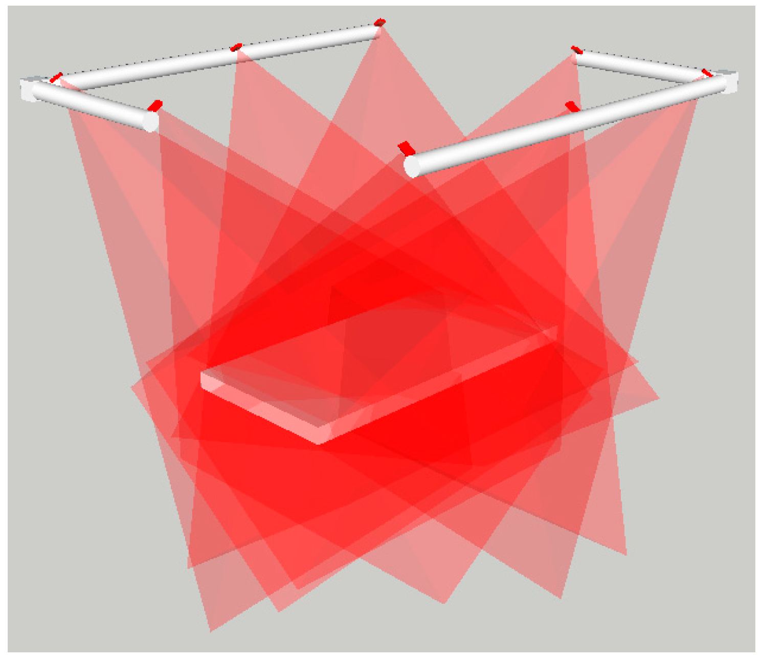
Sensor locations: There is a high restriction on where the sensors to achieve 3D data can be placed, as these devices have to be located in such positions that in no way can interfere with the processes of the operating room. As a requirement, the sensors have to be located around the operating couch, in an approx. height of 1.5 m counted from the top of the couch and forming a rectangle of 2.4 × 3.0 m
2 (see schematic in
Figure 1). Additionally, the complex shapes of the objects (e.g., resected area of the human body) can make that some inner local concave parts are not fully seen by a single position of an optical device and/or cause some inter-reflections. To leverage this, different sensors and/or different positions of the sensors have to be considered.
Figure 1.
Schematic of the NIR camera locations around the treatment coach.
Figure 1.
Schematic of the NIR camera locations around the treatment coach.
Occlusions: There may be up to five different medical staff around the operating couch at different stages of the operation. This fact can cause several occlusions that can be minimized by increasing the number of sensors in such a way that there is always a minimum number of sensors (at least one or two, depending on the applied technique) that are able to visualize the couch at the same time.
Controlled illumination: The ambient light is crucial in optical-based systems and has to be controlled. In the case of the operating room, the available ambient light must be optimal and uniform, so the operating couch can be perfectly seen by the bare eyes (and, thus, by standard cameras) and the lack of windows avoids interference of sunlight (thus, working with NIR cameras and projectors is possible).
Non-rigid object: Though the patient is anesthetized, he/she can make involuntary movements due to breathing. Additionally, the internal organs may also register small movements. This fact highly affects the decision on which methodology to use for the 3D reconstruction. We are interested in using an approach that can acquire all the required information to derive the 3D shape in an instant.
Non-expert users: The system will be used by medical personnel not necessarily expert in optical tracking systems. Thus, it is necessary to design a usable protocol for both calibration and normal usage of the system (see next section).
2.3. Usability Design
As explained before, a multidisciplinary group of surgeons, anesthetists, medical physicists, radiation oncologists (ROs), and technical and nursing staff are involved during the IOERT process, being the main actors the surgeon and the RO. These personnel are not necessarily expert in optical tracking systems. Therefore, a usability protocol must be designed in order to allow our interactive system to be easily used, preventing the risks of malfunctioning and avoiding any possible distraction. The protocol is built by following two essential steps, calibration and acquisition, which are further explained.
Calibration: System calibration is only required if sensors have been moved, though it is highly recommended to be done before and after the acquisition process. The procedure will start when indicated by the medical staff. The system will graphically indicate the necessary steps to be followed, indicating when the procedure finishes. After the calculations are done (a step that should not be time consuming) an indication of the success/failure will be indicated by the system. In case of failure, the medical staff will be asked to repeat the calibration. In case of success, the computed calibration parameters will be automatically incorporated into the system.
Acquisition: Once the system is calibrated, acquisition will start. Similar to the calibration procedure, the medical staff will indicate when the acquisition starts. This procedure should be designed in such a way that the medical staff needs no additional indications while it is running, as this could interfere in the treatment process, which is not desired. When the medical staff finishes the treatment, they will need to indicate to the application that this procedure has finished.
4. Results and Discussion
The different approaches as introduced in
Section 3 were evaluated and further compared in the case of non-rigid objects, where a mannequin body was used as a target shape. In the following paragraphs the outcomes are presented.
In both procedures of tracking rigid objects and in Approach 1 of tracking non-rigid objects, the same technology was used and, thus, the evaluation done is extendable for both.
Some tests were done with the pointer (recall
Section 3.2.1) in order to further calculate the accuracies of the system when measuring single points. These tests were done by using the pointer in two different positions: in diagonal (
i.e., with an inclination angle with respect to the horizontal plane) and in vertical. Points arranged in a grid covering an area of 2.0 × 1.0 m
2 were measured. The resulting errors are depicted in
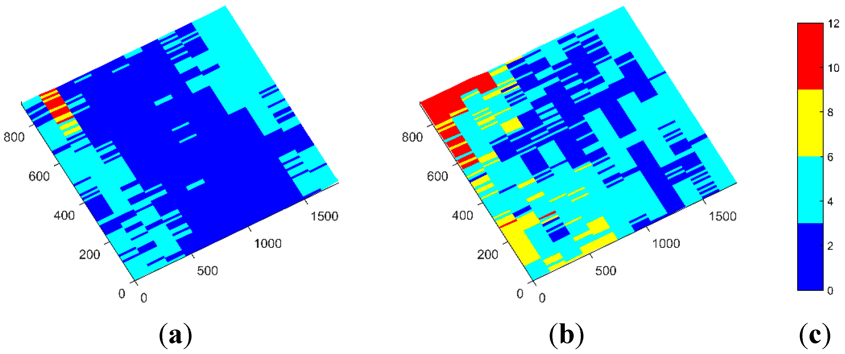
Figure 2. Average errors are in between 4 and 5 mm, where maximum errors that do arise at some of the corners are below 12 mm.
Figure 2.
Obtained errors when measuring with the pointer in two different positions: (a) pointer in the diagonal; (b) pointer in the vertical; and (c) error scale in mm.
Figure 2.
Obtained errors when measuring with the pointer in two different positions: (a) pointer in the diagonal; (b) pointer in the vertical; and (c) error scale in mm.
Although the obtained average errors are inside our requirements, this approach has several limitations that will prevent and/or reduce its use in a real treatment. In the first place, this method consumes tens of seconds to be completed, which can be critical when dealing with non-rigid objects, as the general body positioning can be moved between the registration of one point and the next. Secondly, it is difficult to locate the exact position where the measurements should be done, while it is in many cases impractical to put physical markers in the patient’s body that indicate these locations. This brings another consequence, which is the high dependency of the human factor when acquiring point locations, particularly where a lack of experience could be translated into incorrect point locations. Additionally, with this method the 3D model of the tumor bed cannot be obtained and, thus, the measured points are used to reference the patient with the previously acquired model via CAT. Another problem that arose during the trials with the real operating room regarded the sterilization of the pointer. It was found that the final pointer to be used at the treatments should be of a material able to be sterilized; in the same way, reflective spheres could not be reused.
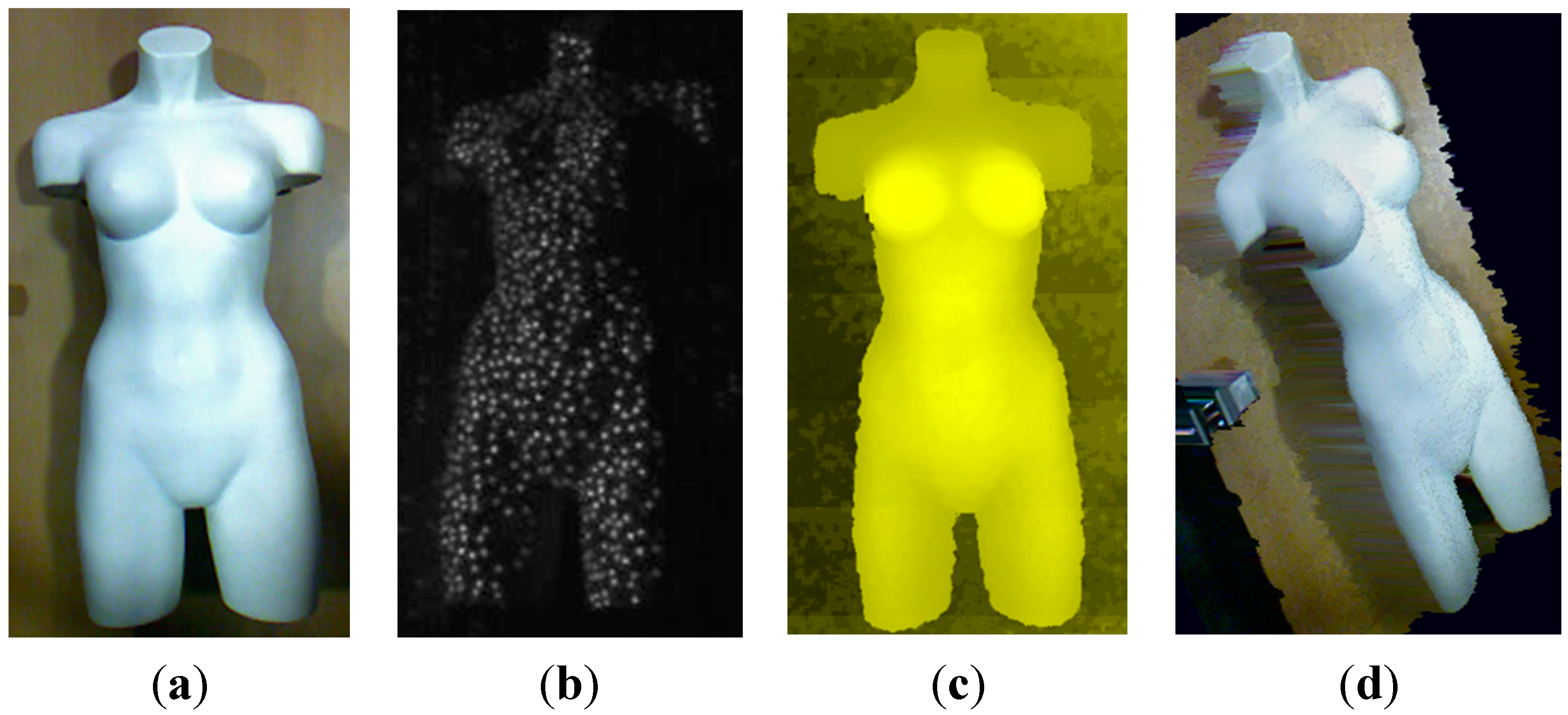
In the second approach of non-rigid objects, a Kinect sensor from Microsoft was used.
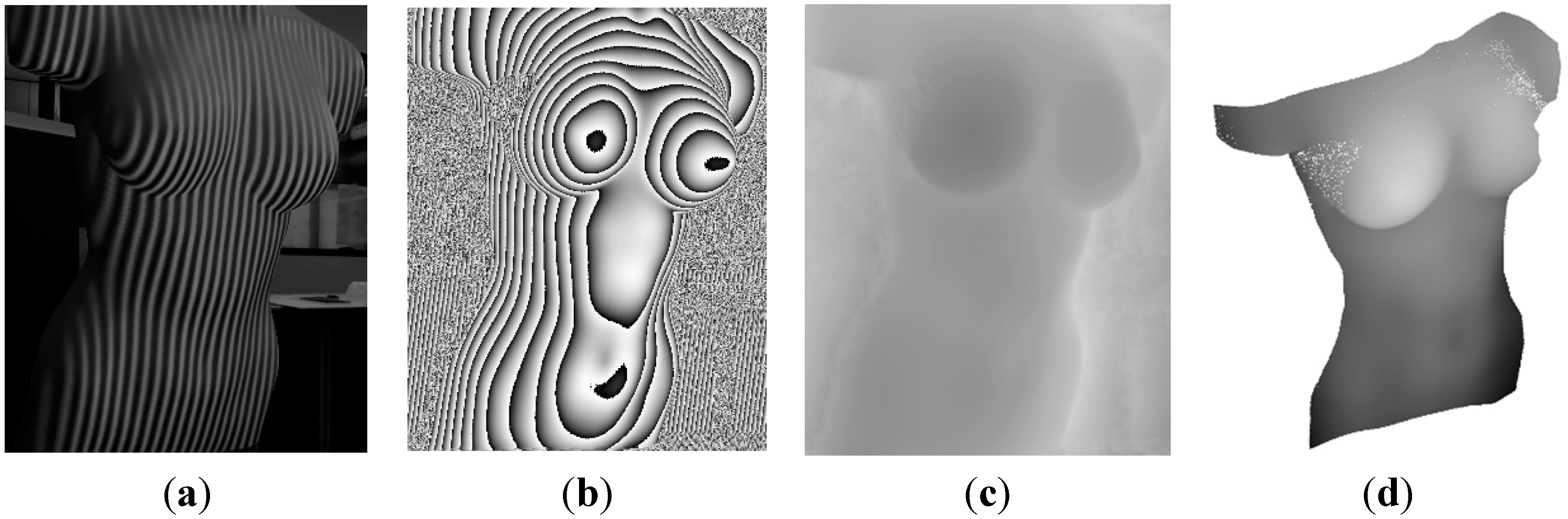
From the depth image, the 3D cloud of points can be calculated with a formula that relates the registered depth values with spatial depth distances. We have implemented a procedure that automatically fulfills this task and additionally computes a texturized mesh with the image given by the visible camera (
Figure 3a). In
Figure 3a–c, the mannequin body used for simulations is depicted as viewed by the different cameras of the Kinect, while in
Figure 3d the reconstructed 3D shape is depicted.
Figure 3.
Calculation of a 3D model from the Kinect sensor, where: (a) physical model as seen by the VIS camera of the Kinect; (b) projected grid pattern as seen by a NIR camera; (c) depth image as acquired by the Kinect sensor; and (d) calculated 3D cloud of points with textured mesh.
Figure 3.
Calculation of a 3D model from the Kinect sensor, where: (a) physical model as seen by the VIS camera of the Kinect; (b) projected grid pattern as seen by a NIR camera; (c) depth image as acquired by the Kinect sensor; and (d) calculated 3D cloud of points with textured mesh.
The main advantage of this system is its capability to work in real-time, while its major inconveniences for our case are the low spatial resolution, the fixed optics and working ranges.
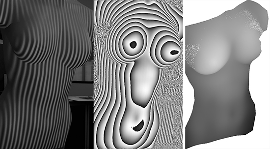
In order to evaluate the third approach of non-rigid objects, different experiments were done, by applying different periods to the projected fringe, from which the best results were acquired with a period of 10 pixels. The computation of the X and Y values of the cloud of points derived from the range image is straightforward, and the Z values are obtained after applying a phase-to-height conversion (
Figure 4).
Figure 4.
Generation of a dense cloud of points after a structured light procedure, where: (a) projected fringe pattern on the body; (b) wrapped phase map; (c) unwrapped phase map; and (d) dense cloud of points.
Figure 4.
Generation of a dense cloud of points after a structured light procedure, where: (a) projected fringe pattern on the body; (b) wrapped phase map; (c) unwrapped phase map; and (d) dense cloud of points.
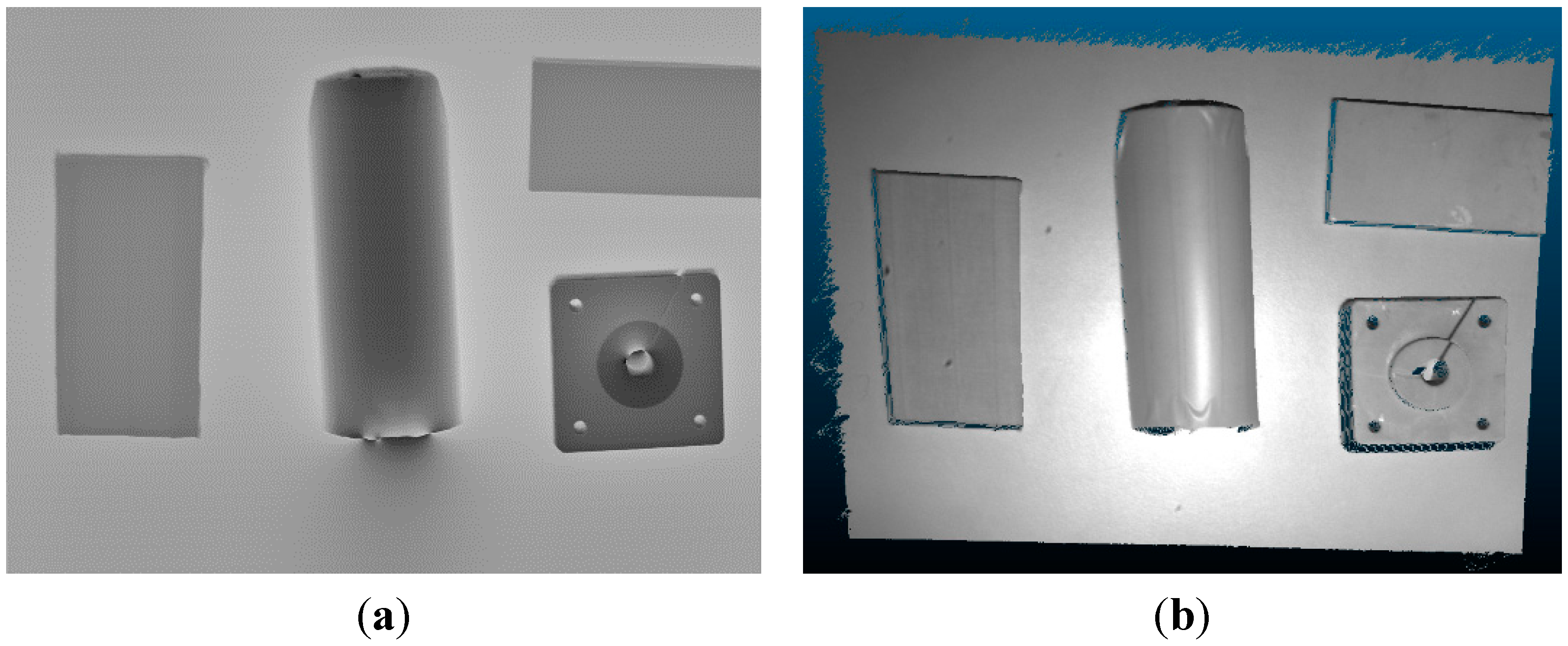
To assess the overall accuracy of our implementation in this case, a 3D calibration body was used which consisted of different objects attached to a planar surface with known height values (
Figure 5). As a result, we obtained a mean error in height of 0.89 mm.
Figure 5.
Calibration shape with known height values, where: (a) calculated phase image; (b) 3D reconstruction.
Figure 5.
Calibration shape with known height values, where: (a) calculated phase image; (b) 3D reconstruction.
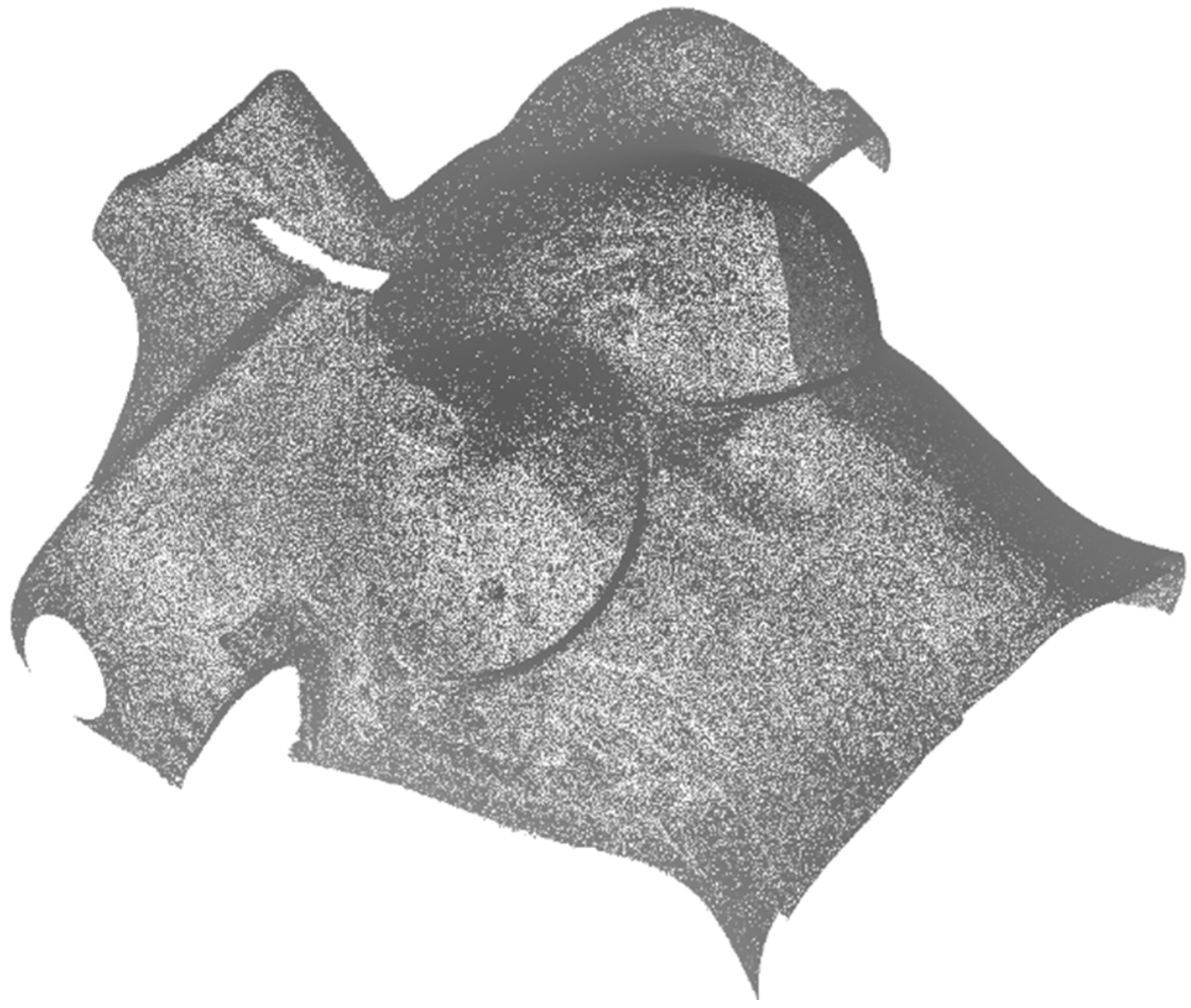
Finally, the body was registered with the NUB3D technology as given in the fourth approach, and the obtained cloud of points was evaluated. Following this approach, we can say that the result of the 3D reconstruction is highly accurate (
Figure 6), as the device has a sub-millimeter accuracy, and of high density. However, the acquisition time increases (around 30 s), as different patterns are projected on the body. Additionally, the total costs of the system is around 10 times of that of the 3D-constructed scanner presented in the third approach.
Figure 6.
3D cloud of points obtained with a professional 3D scanner with sub-millimeter accuracy.
Figure 6.
3D cloud of points obtained with a professional 3D scanner with sub-millimeter accuracy.
As a summary, the pros and contras of the four tested approaches are depicted in
Table 1.
According to our experiments, we can conclude that the Approach 3 is the most appropriate to be installed in an IOERT surgical environment, as it meets speed, efficiency, dense point cloud, and high accuracy at once. A further consideration would be to allow the technology to be placed in different positions, as to avoid possible occlusions and to perform better reconstruction of complex objects, such as those presenting local concave parts. To that end, the devices in Approach 3 have to be mounted on a movable platform of easy manipulation.
Table 1.
Pros and cons of the four studied approaches to register the patient.
Table 1.
Pros and cons of the four studied approaches to register the patient.
| Approach # | Pros | Contras |
|---|
| 1 | Accuracies in the order of 5 mm | Only few points are registered |
| Needs few seconds for acquisition |
| Accuracies and time consuming depends on user experience |
| Sterilisation problems |
| No acquisition of a 3D model |
| 2 | Fast acquisition | Mid resolution |
| Fast processing (real-time) | Limited accuracy |
| Economic | Non-adaptable optics (fixed working distance range) |
| 3 | High resolution (dense cloud of points) | Increase in image resolution leads to higher computational time |
| High accuracy (depending on the calibration method) |
| Adaptable optics |
| Fast acquisition |
| Economic |
| 4 | High resolution (dense cloud of points)
High accuracy
Adaptable optics | Time consuming
More expensive |
5. Conclusions
The IOERT has specific surgical restrictions that make it difficult to incorporate treatment planning. In these surgical environments, the 3D shape of patients is acquired by a CAT system, which is usually carried out some weeks before the treatment and with certainly a different position of what the patient is keeping during the treatment. Therefore, the implementation of a method that allows the acquisition of an accurate 3D shape of the patient’s tumor bed in real-time is of high interest.
The work here presented constitutes a step forward on the spatially registration of the different objects that are relevant in such a surgical treatment. To that purpose, the operating room needs to be sensorized, a non-trivial task that has to account for different restrictions regarding to the operating room itself, to the medical staff involved in the treatment, and to the technological limitations.
Here, we have shown a solution to register rigid objects in real-time by the use of an optical tracking system composed of eight NIR cameras and registration bodies with reflective spheres. Additionally, some preliminary results for acquiring the 3D shape of the patient, which is a non-rigid object, have been presented by means of four different approaches, the first being a point-based registration, while the others are based in 3D scanning techniques. After our analysis, we conclude that the 3D registration of patients in real-time is possible with high accuracies and relatively low costs, provided that the sensing devices and their placement meet the required restrictions of surgical environments.


