Article

Influence of Powder Particle Morphology on the Static and Fatigue Properties of Laser Powder Bed-Fused Ti-6Al-4V Components

by
Salah Eddine Brika
and
Vladimir Brailovski
*
Department of Mechanical Engineering, École de Technologie Supérieure, 1100 Notre-Dame Street West, Montreal, QC H3C 1K3, Canada
*
Author to whom correspondence should be addressed.
J. Manuf. Mater. Process. 2020, 4(4), 107; https://0-doi-org.brum.beds.ac.uk/10.3390/jmmp4040107
Submission received: 18 September 2020 / Revised: 29 October 2020 / Accepted: 5 November 2020 / Published: 9 November 2020

Abstract

:
In this work, two Ti-6Al-4V powder lots were produced using two different techniques: plasma atomization and gas atomization, with the first producing more spherical particles than the second. Testing specimens were then manufactured with these powder lots using an identical set of printing parameters and the same laser powder bed fusion system. Next, the porosity levels and distributions as well as the static and fatigue properties of the specimens from both powder lots were compared. Regarding the static mechanical properties, a noticeable difference was observed between the plasma-atomized powder specimens and their gas-atomized equivalents (7% greater ultimate and 4% greater yield strengths, but 3% lower elongation to failure, respectively). However, with regard to the fatigue resistance, the advantages of the plasma-atomized powder specimens in terms of their mechanical resistance were somewhat counterbalanced by the presence of pores aligned in the direction perpendicular to that of applied load. Conversely, specimens printed with the gas-atomized powder manifested a similar level of porosity, but a uniform pore distribution, which reduced the impact of the processing-induced porosity on fatigue cracks initiation and propagation.

1. Introductions

Laser powder bed fusion (LPBF) is one of the most used processes for the additive manufacturing of complex metallic parts. It consists of spreading successive powder layers with a recoating system (blade and roller) and selectively fusing metallic particles using a high-power laser [1,2].
A large panel of metals and alloys in powdered form can be used to manufacture parts with the LPBF process. These powders are produced using gas, plasma, and water atomization processes, each yielding powders with specific particle characteristics in terms of their morphology, size, internal porosity, and surface texture [3,4]. These characteristics highly influence the flow properties and the packing efficiency of the powders, and multiple studies have investigated these relationships [5,6,7,8]. Common conclusions of these studies include the observation that spherical particles improve the powder flowability and packing efficiency, and that fine particles negatively impact the rheological behavior as they involve a larger contact surface and a propensity to agglomeration. Conversely, if finer particles are present in powders with sufficiently wide particle size distributions (PSDs), they may fill the voids left between the coarser particles, thus increasing the packing efficiency.
The influence of PSDs on LPBF part performances, especially in terms of their density and mechanical properties, is also an active area of research, and numerous studies have already covered it specifically. Some such studies focusing on steel powders [8,9,10,11,12] have reported observations similar to those above, indicating that filling the voids between the coarser particles with an appropriate amount of fine particles can be beneficial for improving parts density, surface finish, and mechanical strength. It has also been reported that, because of their greater thermal absorptivity, coarser particles reduce the degree to which underlying layers undergo remelting, which in turn results in a weaker bonding between layers and in lower strength characteristics of printed parts [9], whereas a specifically selected narrow PSD tends to improve the mechanical resistance and hardness of such parts [13].
Other researchers have focused their studies on the impact of particles morphology on the geometric and mechanical properties of LPBF parts made from titanium alloys. For example, Seyda and Herzog [3] tested three Ti-6Al-4V powder lots produced using different production routes, namely, gas atomization, plasma atomization and induction plasma spheroidization. They noticed that the observed differences in terms of particle morphology and surface texture did not significantly impact the parts densities and mechanical properties. Brika et al. [5] conducted a comparable study with Ti-6Al-4V powders, but showed that more spherical powders have a better rheological behavior, and tend to yield parts with better attributes in terms of density, surface finish, geometric conformity and static mechanical properties than their less spherical equivalents. The authors of the study also pinpointed the fact that the differences in mechanical properties due to different particle morphologies were less significant than those related to rheological behavior, surface roughness and geometric attributes of printed parts. All these results indicate that an appropriate LPBF powder feedstock cannot be devised without significant optimization efforts involving the optimization not only of the powder characteristics, but also of the related LPBF process parameters.
A smaller number of investigations have been conducted to clarify the impact of powder characteristics on the fatigue behavior of LPBF parts [14,15], despite the importance of such studies and the uncertainty associated with the ability of LPBF parts to withstand cyclic loading. Among these, Carrion et al. [16] studied the impact of powder recycling on the tensile and fatigue performance of Ti-6Al-4V LPBF parts. The authors reported that repetitive powder recycling narrows the particle size distribution and increases the powder bed density by simultaneously (a) diminishing the amount of finer particles due to their segregation during powder spreading in the course of printing and (b) reducing the amount of coarser particles in the course of repetitive sieving. They showed that such a phenomenon results in a significant improvement of the fatigue life of specimens produced with the recycled powder, while the static mechanical properties are affected to a much lower extent. Furthermore, Gong et al. [17] studied two Ti-6Al-4V powders with different levels of fines. Regarding tensile properties, comparable results were reported for the two batches. It was however shown that a higher amount of fine particles had a negative effect on the fatigue performance. The authors suggested that finer particles tend to increase the laser absorption of the powder bed, which could in turn lead to the instability of the meltpool and to the appearance of lack-of-fusion defects in the solidified regions.
Despite the many research efforts that have been undertaken, the relationship between the characteristics of powder feedstock and those of printed parts has not yet been established, because of numerous phenomena and interactions involved in the LPBF process. This study endeavors to improve the understanding of this relationship, and to that end, a comparative study of two selected Ti-6Al-4V powder lots (plasma-atomized and gas-atomized) is conducted. The investigation begins with the PSD and morphology characterization of these powder lots, continues with printing of specimens with the selected powder lots using an identical set of LPBF processing parameters and the same LPBF system, and ends with comparative assessment of their processing-induced porosity, static and fatigue mechanical properties, microstructure, and failure analyses.

2. Materials and Methods

2.1. Selection of Powder Lots

To investigate the influence of the powder morphology on the mechanical properties of printed parts, two Ti-6Al-4V powder lots were selected from two suppliers employing different production techniques, namely, gas atomization and plasma atomization. The latter is known to yield more spherical powders than the former [3,4].
The gas-atomized powder was supplied by EOS (EOS GmbH, Munich, Germany), while the plasma-atomized powder was provided by PyroGenesis (PyroGenesis Additive, Montreal, QC, Canada). Information on the chemical compositions of the two powder lots was provided by the powder producers, and met the specifications defined by the ASTM B348—Grade 5 standard, as shown in Table 1.

2.2. Powder Lot Characterization

Computed tomography inspections (XT H225 μ-CT system, Nikon, MI, USA) were carried out in order to evaluate the geometric attributes of the powder particles, i.e., their size and sphericity. A glass capillary tube (inner diameter of 0.8 mm, wall thickness of 0.1 mm, length of 32 mm) was filled with powder and scanned using a transmission scan source with a beryllium target configured with a 145 kV scan voltage and 19 μA beam current. The specimen position in the machine allowed the obtention of a voxel size of 1.331 μm3. CT PRO 3D software (Nikon, MI, USA) was used to reconstruct the obtained images and the post-treatment was carried out using Dragonfly software (Object Research Systems, Montreal, QC, Canada) to isolate different particles and evaluate their geometric attributes. Features smaller than 1 µm were excluded from the analysis to eliminate the image noise detected as a feature in the scanned sample. The configuration considered (sample size and resolution) allowed the analysis of ~15,000 particles per powder sample.
In order to generate the volume-based particle size distributions, the diameters of the volume-equivalent spheres were calculated using the following formula [18],
D v = ( 6 π   V p ) 1 3
where D v is the diameter of the volume-equivalent sphere and V p is the volume of a particle. Particle sphericity was estimated using the following formula [18],
S p h e r i c i t y =   S s S p
where S p is the surface area of a particle of a given volume and S s is the surface area of an equivalent sphere with the same volume as the particle studied. Particles morphology was also analyzed visually using a Hitachi TM3000 scanning electron microscope (Tokyo, Japan).

2.3. Manufacture of LPBF Specimens

To study the impact of the particle morphology on the static and fatigue mechanical properties of LPBF components, tensile and fatigue specimens were oriented perpendicular to the build plate and manufactured with the selected powder lots. Rectangular prismatic 80 × 16 × 3 mm3 blanks were printed and then machined to obtain dumbbell-shaped tensile specimens with a gauge length of 27 mm, as shown in Figure 1a. Cylindrical 16 mm diameter and 110 mm height blanks were printed and machined to obtain specimens with tangentially blending fillets between the test section and the extremities according to the ASTM-E466-15 standard, as shown in Figure 1b.
All the specimens of this study were manufactured using an M280 400 W Ytterbium fiber laser system (EOS GmbH, Munich, Germany) equipped with an HSS (high speed steel) doctor blade and the default program provided by the manufacturer, i.e., the “Ti64 Performance” (PSW version 3.6). The LPBF parameters used were laser powder, 280 W; scanning speed, 1200 mm/s; hatching distance, 140 µm; and layer thickness, 30 μm. Several replicates were printed for each specimen type (25 prismatic blanks for tensile specimens and 20 cylindrical blanks for fatigue specimens) and heat-treated, while on the build plate, using the EOS-recommended stress relief conditions (800 °C for 4 h in argon atmosphere) in a Nabertherm N41/H furnace (Lilienthal, Germany).

2.4. Characterization of Printed Specimens

2.4.1. Processing-Induced Porosity

In order to characterize the processing-induced porosity, a computed tomography inspection of the gauge sections of printed specimens was carried out using an XT H225 X-ray μ-CT (computed tomography) system (Nikon, MI, USA). The specimens were scanned using a transmission scan source with a beryllium target configured with a 210 kV scan voltage and 50 μA beam current. The specimen position in the machine allowed the obtention of a voxel size of 15 μm3. The obtained images were reconstructed using CT PRO 3D software (Nikon, MI, USA) and post-treated using Dragonfly software (Object Research Systems, QC, Canada) in order to detect the presence of processing-induced flaws and evaluate their geometric attributes, i.e., the size, the aspect ratio, and the position. Detected features smaller than 3 µm were excluded from the analysis to eliminate the image noise considered as features in the scanned specimens.

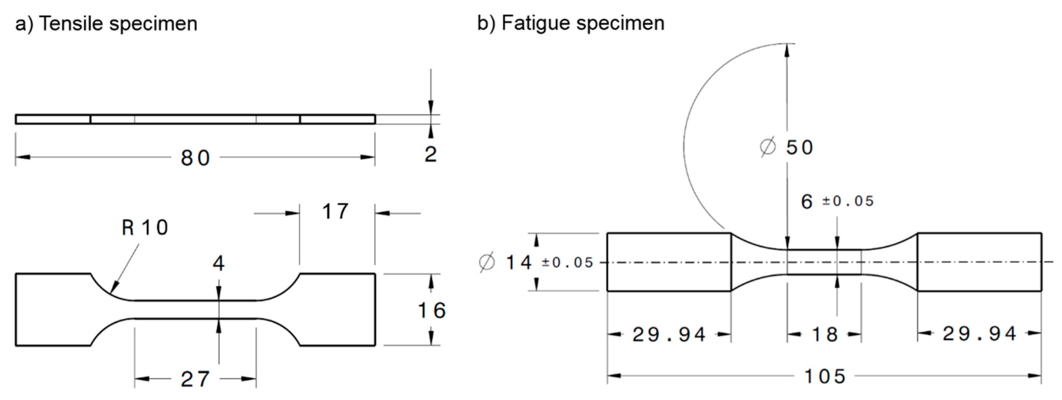
2.4.2. Tensile Properties

Tensile testing was performed on a MiniBionix 858 servo-hydraulic system (MTS, Eden Prairie, MN, USA) coupled with an MTS 634.12E-25 extensometer and having a crosshead speed of 0.375 mm/min, corresponding to a strain rate of 0.8 s−1. For each configuration studied, three repetitions were carried out. Based on the stress–strain diagrams produced, the mechanical properties, i.e., the Young’s modulus E (GPa), the ultimate tensile strength UTS (MPa), the yield strength YS (MPa) and the elongation at break δ (%) were evaluated. A total of 4 specimens from each powder lot were tested to obtain the static mechanical properties.

2.4.3. Fatigue Properties

Fatigue testing was conducted on a LANDMARK 370 servo-hydraulic system (MTS, Eden Prairie, MN, USA) using the stress-controlled fatigue testing method in accordance with the ASTM E466 standard. Testing was carried out with a stress ratio of R = 0.1 applied in a sinusoidal waveform with a frequency of 15 Hz. An MTS 661.20H-03 force transducer and an MTS LVDT were used to monitor forces and displacements (10 cycles were recorded for each 1000 cycles). The number of cycles to failure was also recorded with a runout defined at 107 cycles. A total of 18 specimens from each powder lot were tested to obtain the S-N curve.

2.4.4. Failure Analysis

Fractographic analyses were carried out on two specimens printed from different powder lots and that had failed under the same alternated stress of 800 MPa. Prior to the examination, the specimens were prepared by cutting a part from their gauge section near the fracture area. A Hitachi S3400-N SEM in secondary electron mode at 20 kV was used to examine the fracture surfaces and identify the fatigue crack initiation sites.

2.4.5. Microstructure Analysis

In order to compare microstructures of specimens printed with two powder lots, two plane surfaces were considered, namely, the XZ plane (parallel to the build direction) and the XY plane (perpendicular to the build direction). After cutting, both surfaces were prepared starting by a manual polishing then using a vibrometer with colloidal silica and finishing by ion milling. A Hitachi SU8230 scanning electron microscope (SEM), equipped with an electron backscatter diffraction unit, was used to carry out an electron backscatter diffraction (EBSD) analysis (70° tilt angle, energy 25 kV, ×300 and ×1500 magnifications). Additionally, X-ray analysis (XRD) of specimens printed with two powder lots (XY plane) was performed using a PANanalytical X′Pert Pro diffractometer with Co-Kɑ radiation at 45 kV and 40 mA, under a continuous scanning mode over a 35–55° 2 theta angle range.

3. Results

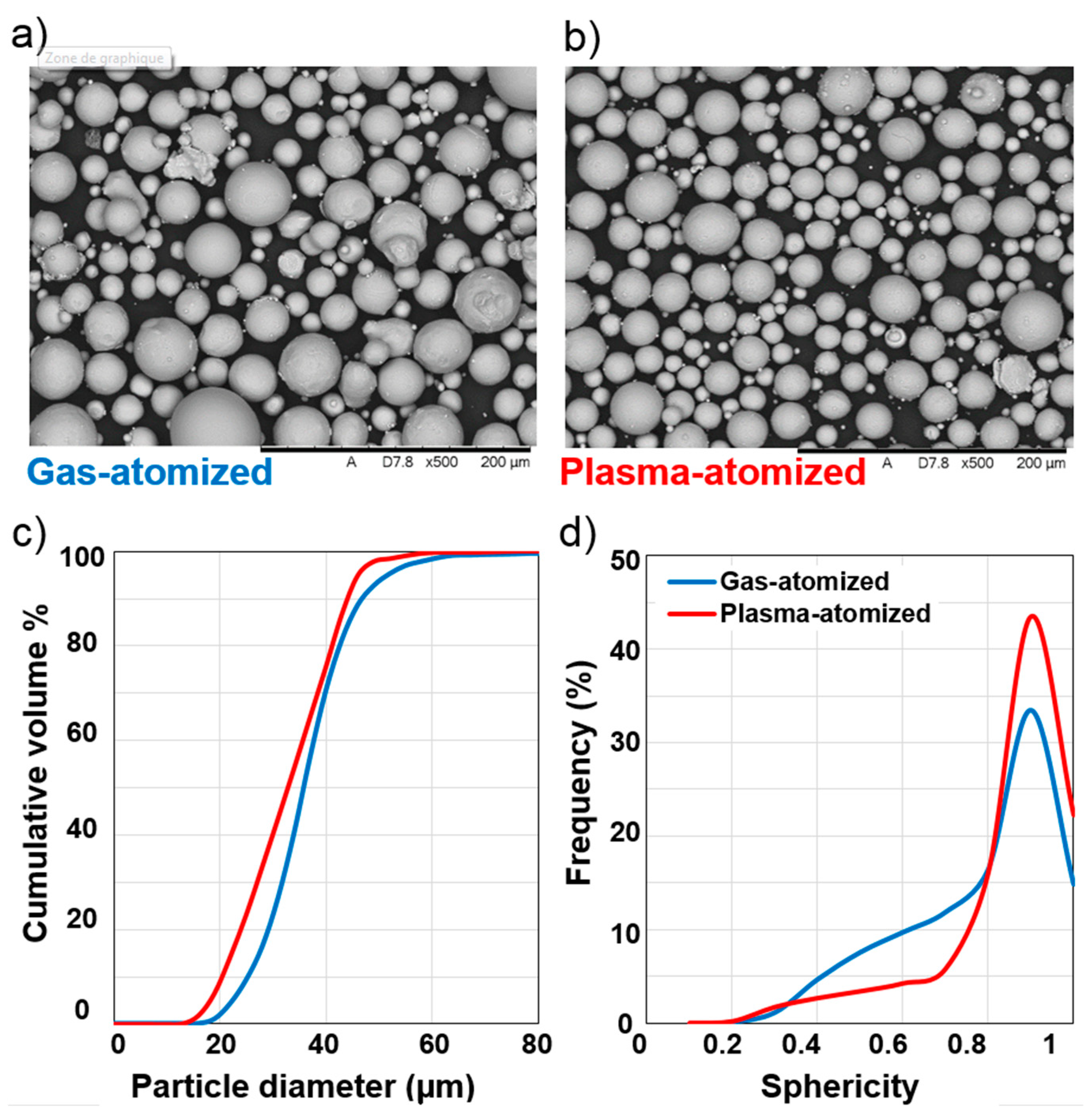
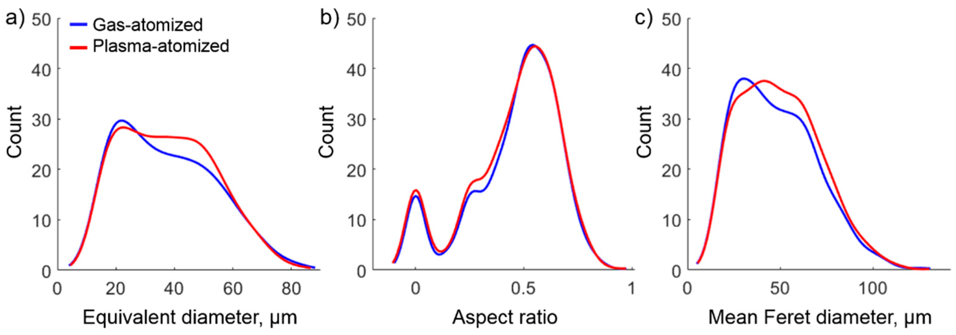
3.1. Particle Size Distribution and Morphology

Regarding the particle size distribution of the selected powder lots (Figure 2c and Table 2), it can be seen that the two powders have significantly similar PSDs, with the plasma-atomized powder having a slightly wider distribution shifted toward finer particles. The SEM micrographs shown in Figure 2a,b illustrates the difference between the two lots in terms of particles morphology, with the plasma-atomized powder particles being more spherical and regularly shaped than their gas-atomized equivalents. The rougher particle surface and presence of some agglomerates can also be noticed in the latter mentioned powder lot micrograph. The micro computed tomography-based analysis (µCT) can further refine these observations (Figure 2d and Table 2), where more than 50% of the plasma-atomized particles manifest a sphercity index higher than 0.84 (D50 = 0.84 vs. 0.79 for the gas-atomized powder, 1 referring to a perfect sphere). The production routes used can explain the observed differences in the particle morphologies, as discussed in [4], with the plasma atomization technique yielding more spherical particles than the gas atomization technique.

3.2. Characterization of Printed Specimens

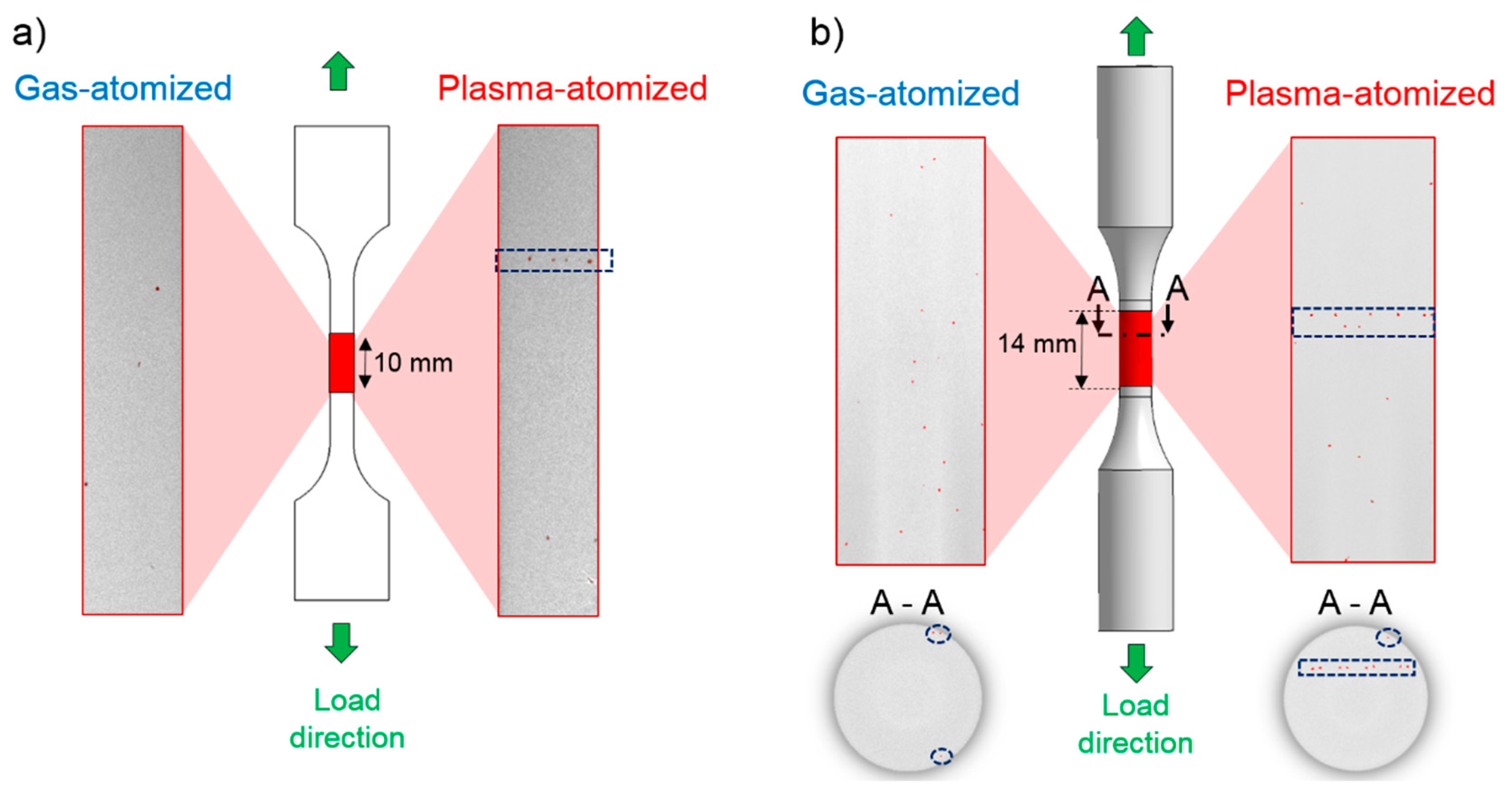
3.2.1. Internal Defects

Computed tomography combined with imaging processing allowed the identification of internal defects in the specimens produced with the two powder lots. Both powders yielded highly dense parts (>99%), with a slight difference in their average porosities: gas-atomized powders, ~0.15% and plasma-atomized powders, ~0.1%. Different metrics of interest were measured for the detected pores, considering ~1800 pores per specimen (after noise filtering). It can be seen in Figure 3a–c that specimens printed from both powder lots contain pores of comparable distributions and morphologies.
A further analysis of the 3D reconstructed images revealed certain patterns in the distribution of internal defects in the plasma-atomized powder specimens (Figure 4a,b). The presence of aligned pores in these specimens could be explained by the fact that the LPBF processing parameters used to print with both powders were optimized for the gas-atomized powder only (this powder was supplied by the LPBF system manufacturer). Aligned pores, especially along the horizontal plan (perpendicular to the direction of loading during testing), could affect the specimen performance during static and even more significantly, fatigue testing.
The presence of pores near the specimen surface (Figure 4b) was also observed during the computed tomography analysis, this time, in specimens printed with both powders. The position of these defects could be critical, especially during fatigue testing, and could facilitate the initiation of cracks in the specimen. It should be noted that the observed subsurface pores were not caused by contouring during printing since the standard fatigue specimens were machined from printed cylindrical blanks.
It should be noted that for each powder lot, two fatigue specimens, one tensile specimen, and two cylindrical coupons for density characterization were scanned, and defect clustering similar to that shown in Figure 4a,b was observed in all the samples printed with the plasma-atomized powder.

3.2.2. Tensile Properties

The static mechanical properties, namely, the ultimate tensile strength UTS (MPa), the yield strength YS (MPa), the elongation at break δ (%), and the Young’s modulus E (GPa), were evaluated for the specimens manufactured with both powder lots. For each property, the average and the corresponding standard deviation values are shown in Figure 5, and the numerical values can be found in Table 3. For both powders, the requirements for static mechanical properties of Ti-6Al-4V—Grade 5 presented in ASTM F2924-14 are satisfied (UTS > 895 MPa, YS > 825 MPa, and δ > 10%).
Specimens manufactured with the plasma-atomized powder show higher ultimate tensile strength and yield strength values with a 7% and 4% difference, respectively, as compared to their gas-atomized powder equivalents. Conversely, their ductility is 3% lower than that of their gas-atomized powder equivalents. To validate the statistical significance of the results obtained, the student test (t-test) was used. The p-values were used as indicators, a value smaller than 0.05 indicates that the difference between the means of the results at the 5% significance level is considered to be statistically significant. The p-values obtained for each property are presented in Table 3. The difference is statistically significant for the values of ultimate tensile strength and elongation at break. The difference for the values of yield strength is close to a threshold of the statistical significance (p-value 0.07), while that for the Young’s moduli is significantly greater than the threshold of statistical significance.
It can be seen that the results obtained with the plasma-atomized powder specimens show slightly lower standard deviation values. It could be hypothesized that a more efficient particle packing of the plasma-atomized powder yields a more uniform powder bed density, and therefore more homogeneously printed specimens with better repeatability in their mechanical behavior. Further studies are required to confirm or infirm this hypothesis.

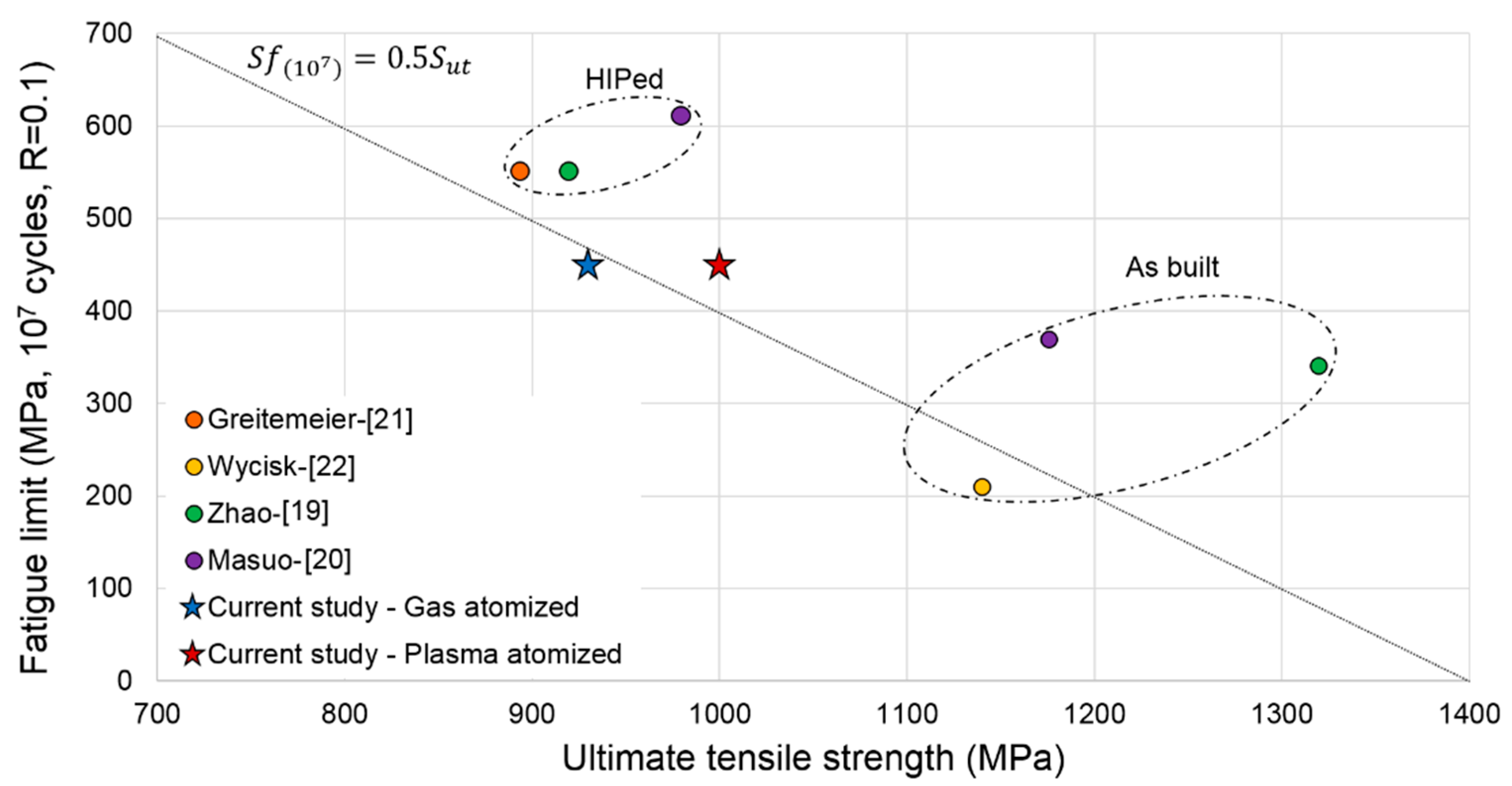
3.2.3. Fatigue Properties

Following fatigue testing, S-N data are reported in Figure 6 with two straight trendlines plotted to minimize their mean square deviations. Some data points were excluded and considered as outliers for obtaining fatigue life values significantly longer or shorter than expected at a given alternated stress level. All the specimens fractured in their gauge sections. Significant discrepancies in the results obtained did not allow an observation of a clear stable region in the established trendline. However, both powders registered runouts (Nf >107 cycles) starting at 450 MPa and lower.
The correlation coefficient is 0.678, which indicates a moderately strong relationship between the obtained results of the two powders. Despite the presence of overall comparable results, it can be noted that the plasma-atomized powder specimens achieved slightly better fatigue performances for stress levels higher than 600 MPa. Discrepancies in the results observed could be explained by the presence of a relatively significant number of internal defects in the printed specimens causing scattering in the results obtained and complicating the differentiation between the performances of the two powder lots.
A survey of the literature on the fatigue resistance of LPBF Ti-6Al-4V specimens submitted to comparable testing conditions (stress ratio R = 0.1, runout 107 cycles, vertically printed) was conducted. A comparison between the results obtained within this work and the fatigue limits reported in the literature [19,20,21,22] is presented in Figure 7. The results obtained within this study falls within the range delimited by the mechanical performances of HIPed (hot-isostatically pressed) and as-built specimens. It can be observed, in the context of this diagram, that plasma-atomized powder specimens manifest a slightly better combination of static and fatigue mechanical properties than their gas-atomized equivalents. It can also be seen that the HIPed specimens demonstrate a longer fatigue life, but a lower static strength, while the as-built specimens manifest a shorter fatigue life, while a higher static strength.

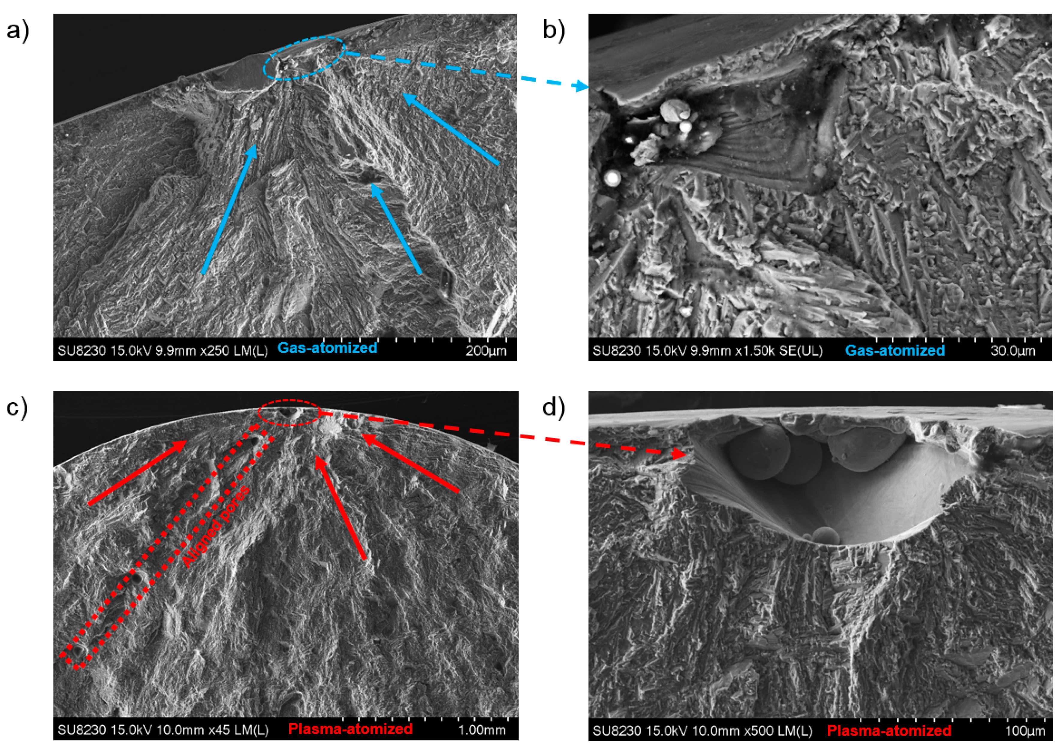
3.2.4. Fractographic Examination

Figure 8 shows the images obtained from the fractographic examination of one specimen from each of the powder lots that failed at the same maximum stress of 800 MPa. In both cases, the fracture initiated from an irregularly shaped lack-of-fusion defect close to the specimen surface. Single crack initiation sites were observed in both specimens. In the plasma-atomized powder specimen, a significant number of spherical pores are present on the fracture site with aligned patterns, which is in agreement with the observations made using the computed tomography technique.

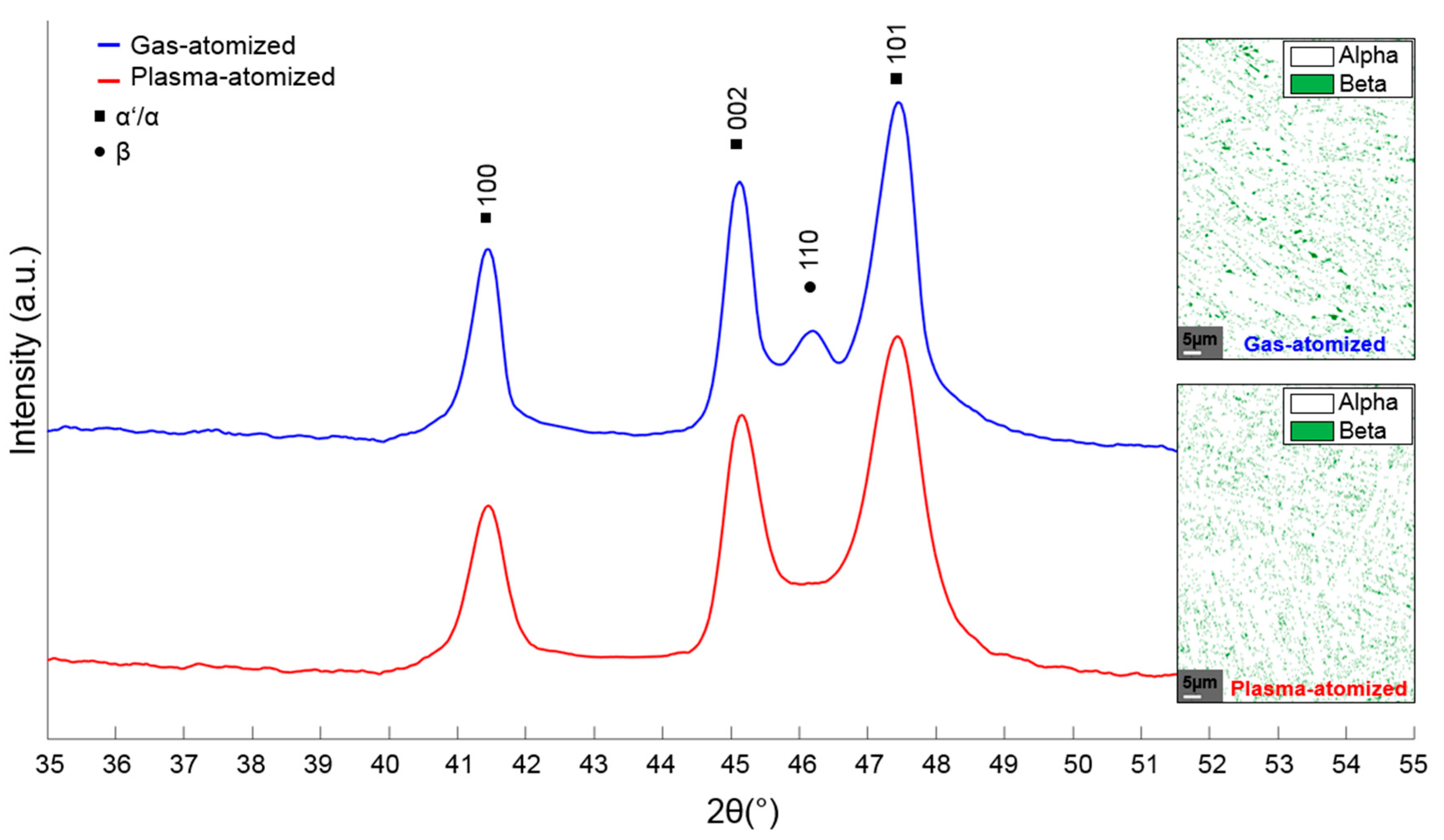
3.2.5. Microstructure Analysis

The diffraction patterns obtained from specimens printed with two powder lots and subjected to a stress relieve annealing are presented in Figure 9. The XRD analysis shows that the both specimens contain predominantly ɑ′/ɑ phase (note that the ɑ′ phase peaks cannot be distinguished from those of ɑ phase using this analysis). Furthermore, the presence of a weak β phase peak between the (002) ɑ′/ɑ and (101) ɑ’/ɑ peaks indicates that the gas-atomized powder specimens contain a greater quantity of β phase than their plasma-atomized powder equivalents. This last observation is supported by the phase distribution maps presented in Figure 9, where the gas-atomized powder specimen reveals a slightly larger amount of β phase than its plasma-atomized powder counterpart: ~5.6% versus ~5.3% of β phase, respectively (the calculations are based on the EBSD maps taken from the XY and XZ planes, Figure 10).
Figure 10 shows the EBSD images of the XY and XZ planes of the specimens produced with the two powder lots. A typical lamellar structure can be observed in both specimens. According to the literature [23], the lamellar (α + β) structure of the LPBF Ti64 alloy is a result of the acicular/lamellar ɑ′ martensite decomposition during stress relief annealing. Using the Burgers orientation relationship between the α (HCP) and β (FCC), the grain boundaries of prior β phase were reconstructed (black lines in Figure 10). It can be seen on the XZ plane, that the prior β phase grains cross more than one-layer thickness and they are somewhat stretched along the build direction (BD). On the XY plane however, the grains are a seemingly more equiaxed. In addition, among the coarser grains, some smaller equiaxed grains can also be observed, and it seems that the fraction of such small grains is greater in the specimens printed with the plasma-atomized powder than with its gas-atomized equivalent.
The average β phase equivalent grain size on both the XZ and XY planes was calculated and the results are collected in Table 4 (~50 grains per configuration were considered). The student test (t-test) was used to compare the results obtained, considering that smaller than 0.05 p-values indicate that the differences between the means of the results could be considered statistically significant at a 5% significance level. It can be seen from p-values in Table 4 that the difference in the equivalent β phase grain sizes between specimens printed with two powder lots is not statistically significant for both the XZ or XY planes. However, when comparing the equivalent grain sizes measured on the XZ and XY planes of the same specimen, a grain aspect ratio (XZ/XY) of ~2 for specimens printed from both powder lots confirms a strong, and comparable, anisotropy of the printed structures.
Moreover, the α-phase lamellae lath widths were also measured and yielded 1.23 ± 0.8µm for the gas-atomized powder specimens as compared to 1.55 ± 1 µm, for their plasma-atomized powder equivalents. This difference was also not found to be statistically significant. Given the fact that differences in size of the β-phase grains and α-phase lamellae observed in specimens printed with two powder lots are not statistically significant, their microstructures could be considered comparable. However, a higher fraction of β phase witnessed by XRD could explain a slightly better ductility of specimens printed with the gas-atomized powder as compared to those printed with the plasma-atomized powder (Figure 5, Table 3).

4. General Discussion

An analysis of the processing-induced defects using the computed tomography technique reveals the following critical point: despite comparable levels of density of the specimens produced with the two powders (>99.1%), pores appear in certain patterns in the plasma-atomized powder specimens that potentially influence their performances. This observation highlights the benefits of using such an advanced NDT technique such as computed tomography to control the level of processing-induced defects, without entirely relying on simplistic density measurement techniques such as Archimedes’, for example. The defect distribution must be considered as one of the critical metrics of the printed parts, that requires as much attention as the parts density.
These aligned defects are the most likely caused by an inadequate track overlapping in the case of the plasma-atomized powder, since they are oriented along the laser tracks. Conversely, this is not an issue in the case of the gas-atomized powder recommended by the LPBF system manufacturer, since pores in specimens printed from this powder were distributed uniformly. This discrepancy could be explained by the difference in the powder bed density presented in Table 5 (see also in [5]) where the plasma-atomized powder yields a 5% denser powder bed than the gas-atomized powder. A tightly packed powder layer limits the penetration of laser radiation (lower laser energy absorptivity [24,25] resulting in a smaller meltpool [26]. Because of that, more energy would be required to form a meltpool of comparable dimensions with the former powder that with the latter. As the same printing parameters were used for both powders of this study, and these parameters were specifically optimized for the gas-atomized powder, overlapping of laser tracks in the case of the plasma-atomized powder was not sufficient to prevent the appearance of pores aligned along these tracks.
This notwithstanding, the results obtained highlight the sensitivity of the process to slight variations in the powder characteristics and illustrate the importance of optimizing the printing parameters for any candidate powder feedstock. A further optimization of the printing parameters and the use of Hot Isostatic Pressing (HIP) post-fusion treatment could be beneficial in reducing the level of processing-induced defects, and therefore could further improve the quality and performances of the produced parts [20,27].
To further leverage the data obtained using the computer tomography technique, it would be very valuable to develop a numerical tool capable of grouping the aligned defects and to evaluate the angle they form with respect to the load applied. In this study, an attempt was made to develop such a dedicated algorithm, but due to the large number of defects in the specimens studied, the computational time was an issue, and more programming optimization efforts are needed to develop such a tool.
It must also be mentioned that the two powder lots in this study had already previously been compared in terms of their flow behavior, powder bed density, and the geometric attributes of printed components (in Table 5, see a brief summary of the main results reported in [5]).
A rheological analysis performed showed a significant advantage of the plasma-atomized powder in respect to its gas-atomized equivalent in terms of powder flowability (~35%). This advantage with regard to the powder bed density (~5%) and the geometric attributes of printed parts (~10%) was less significant. Furthermore, the plasma-atomized powder yielded slightly more resistant (~5%), but slightly less ductile (3%), specimens. This attenuation of differences between the two powder lots can be explained by the fact that the powder bed density and the geometric and mechanical attributes of printed parts depend not only on the powder characteristics, but also on the conditions of powder spreading, printing, and postprocessing.
The differences between the two powder lots with regard to their fatigue resistance become even less apparent, and are blurred by the differences in pore distributions in the specimens printed: aligned pores in the plasma-atomized powder specimens versus homogeneously-distributed pores in their gas-atomized powder equivalents. The XRD and EBSD analyses revealed overall comparable microstructures of the specimens produced with two powder lots (differences in size of the β-phase grains and α-phase lamellae were not found to be statistically significant), thus supporting the hypothesis that the processing-induced porosity constitutes a dominant factor influencing the mechanical behavior, especially the fatigue performance, of the printed specimens of this study. The optimization of LPBF processing parameters for the plasma-atomized powder appears to be a necessary step for a more comprehensive comparison of the plasma and gas-atomized powders of this study in terms of their performances as LPBF powder feedstocks. To this end, a combined numerical modeling-design of experiment approach presented in [26] can be used. This processing optimization approach, which is based on the meltpool calculations and experimental measurements of the printed density and grain size, was successfully applied for Ti-, Ni-, Fe-, and Al-based alloy powders in [28].

5. Conclusions

Two Ti-6Al-4V powder lots with close particle size distributions were selected to investigate the impact of particle morphology on the LPBF process performances in regard to their static and fatigue mechanical properties. For static properties, the plasma-atomized powder specimens showed a slightly higher resistance, but a slightly lower ductility as compared to their gas-atomized equivalents. For fatigue properties, the presence of a certain number of processing-induced flaws in the plasma-atomized powder specimens made the comparison of the two powders more complicated. The occurrence of such flaws in the plasma-atomized powder specimens is attributed to the use of suboptimal printing conditions, which put them at a disadvantage as compared to their gas-atomized equivalents, printed under optimized printing conditions. To reach a definitive conclusion about the comparative performances of the plasma and gas-atomized powders, both powders must be printed using their respectively-optimized processing conditions.

Author Contributions

Conceptualization, S.E.B. and V.B.; methodology, S.E.B. and V.B.; software, S.E.B.; validation, S.E.B. and V.B.; formal analysis, S.E.B.; investigation, S.E.B.; data curation, S.E.B.; writing—original draft preparation, S.E.B.; writing—review and editing, V.B.; visualization, S.E.B. and V.B.; supervision, V.B.; project administration, V.B.; funding acquisition, V.B. All authors have read and agreed to the published version of the manuscript.

Funding

This research was funded by Natural Sciences and Engineering Research Council of Canada (NSERC) within the Discovery grant program.

Acknowledgments

The authors would like to express their appreciation for the support provided by PyroGenesis Additive Canada and Object Research Systems (ORS) Inc. and to thank C. Dion, M. Letenneur, M. Saadati, A. Timercan, A. Kreitcberg, S. Plamondon, and W. Saulnier for their assistance during this project.

Conflicts of Interest

The authors declare no conflict of interest.

References

  1. Campbell, I.; Diegel, O.; Kowen, J.; Wohlers, T. Wohlers Report 2017 3D Printing and Additive Manufacturing State of the Industry: Annual Worldwide Progress Report; Wohlers Associates: Fort Collins, CO, USA, 2017. [Google Scholar]
  2. Sun, S.; Brandt, M.; Easton, M. Powder bed fusion processes: An overview. In Laser Additive Manufacturing; Elsevier: Amsterdam, The Netherlands, 2017; pp. 55–77. [Google Scholar]
  3. Seyda, V.; Herzog, D.; Emmelmann, C. Relationship between powder characteristics and part properties in laser beam melting of Ti–6Al–4V, and implications on quality. J. Laser Appl. 2017, 29, 22311. [Google Scholar]
  4. Chen, G.; Zhao, S.Y.; Tan, P.; Wang, J.; Xiang, C.S.; Tang, H.P. A comparative study of Ti-6Al-4V powders for additive manufacturing by gas atomization, plasma rotating electrode process and plasma atomization. Powder Technol. 2018, 333, 38–46. [Google Scholar] [CrossRef]
  5. Brika, S.E.; Letenneur, M.; Dion, C.A.; Brailovski, V. Influence of particle morphology and size distribution on the powder flowability and laser powder bed fusion manufacturability of Ti-6Al-4V alloy. Addit. Manuf. 2020, 31, 100929. [Google Scholar] [CrossRef]
  6. Strondl, A.; Lyckfeldt, O.; Brodin, H.; Ackelid, U. Characterization and control of powder properties for additive manufacturing. JOM 2015, 67, 549–554. [Google Scholar] [CrossRef]
  7. Karapatis, N.P.; Egger, G.; Gygax, P.E.; Glardon, R. Optimization of powder layer density in selective laser sintering. In Proceedings of the 1999 International Solid Freeform Fabrication Symposium, Austin, TX, USA, 9–11 August 1999; pp. 255–263. [Google Scholar]
  8. Spierings, A.B.; Levy, G. Comparison of density of stainless steel 316L parts produced with selective laser melting using different powder grades. In Proceedings of the Annual International Solid Freeform Fabrication Symposium, Austin, TX, USA, 3–5 August 2009; pp. 342–353. [Google Scholar]
  9. Spierings, A.B.; Herres, N.; Levy, G. Influence of the particle size distribution on surface quality and mechanical properties in AM steel parts. Rapid Prototyp. J. 2011, 17, 195–202. [Google Scholar]
  10. Bourell, D.; Leu, M.; Rosen, D. Roadmap for additive manufacturing-Identifying the future of freeform processing. The University of Texas at Austin, Laboratory for Freeform Fabrication. Adv. Manuf. Cent. 2009, 32, 11–15. [Google Scholar]
  11. Abd-Elghany, K.; Bourell, D.L. Property evaluation of 304L stainless steel fabricated by selective laser melting. Rapid Prototyp. J. 2012, 18, 420–428. [Google Scholar]
  12. Badrossamay, M.; Yasa, E.; van Vaerenbergh, J.; Kruth, J.-P. Improving productivity rate in SLM of commercial steel powders. Technol. Pap. Manuf. Eng. 2009, TP09PUB17, 1–13. [Google Scholar]
  13. Liu, B.; Wildman, R.; Tuck, C.; Ashcroft, I.; Hague, R. Investigation the Effect of Particle Size Distribution on Processing Parameters Optimisation in Selective Laser Melting Process. Available online: https://www.researchgate.net/publication/268365007_Investigaztion_the_effect_of_particle_size_distribution_on_processing_parameters_optimisation_in_selective_laser_melting_process (accessed on 8 November 2020).
  14. Seifi, M.; Gorelik, M.; Waller, J.; Hrabe, N.; Shamsaei, N.; Daniewicz, S.; Lewandowski, J.J. Progress towards metal additive manufacturing standardization to support qualification and certification. JOM 2017, 69, 439–455. [Google Scholar] [CrossRef]
  15. Seifi, M.; Salem, A.; Beuth, J.; Harrysson, O.; Lewandowski, J.J. Overview of materials qualification needs for metal additive manufacturing. JOM 2016, 68, 747–764. [Google Scholar] [CrossRef] [Green Version]
  16. Carrion, P.E.; Soltani-Tehrani, A.; Phan, N.; Shamsaei, N. Powder recycling effects on the tensile and fatigue behavior of additively manufactured Ti-6Al-4V parts. JOM 2019, 71, 963–973. [Google Scholar] [CrossRef] [Green Version]
  17. Gong, H.; Dilip, J.J.S.; Yang, L.; Teng, C.; Stucker, B. Influence of small particles inclusion on selective laser melting of Ti-6Al-4V powder. In Proceedings of the IOP Conference Series: Materials Science and Engineering, Prague, Czech Republic, 21–22 September 2017; Volume 272, p. 12024. [Google Scholar]
  18. Pabst, W.; Gregorova, E. Characterization of particles and particle systems. ICT Prague 2007, 122, 122. [Google Scholar]
  19. Zhao, X.; Li, S.; Zhang, M.; Liu, Y.; Sercombe, T.B.; Wang, S.; Hao, Y.; Yang, R.; Murr, L.E. Comparison of the microstructures and mechanical properties of Ti--6Al--4V fabricated by selective laser melting and electron beam melting. Mater. Design 2016, 95, 21–31. [Google Scholar] [CrossRef]
  20. Masuo, H.; Tanaka, Y.; Morokoshi, S.; Yagura, H.; Uchida, T.; Yamamoto, Y.; Murakami, Y. Influence of defects, surface roughness and HIP on the fatigue strength of Ti-6Al-4V manufactured by additive manufacturing. Int. J. Fatigue 2018, 117, 163–179. [Google Scholar] [CrossRef]
  21. Greitemeier, D.; Palm, F.; Syassen, F.; Melz, T. Fatigue performance of additive manufactured TiAl6V4 using electron and laser beam melting. Int. J. Fatigue 2017, 94, 211–217. [Google Scholar] [CrossRef]
  22. Wycisk, E.; Solbach, A.; Siddique, S.; Herzog, D.; Walther, F.; Emmelmann, C. Effects of defects in laser additive manufactured Ti-6Al-4V on fatigue properties. Phys. Procedia 2014, 56, 371–378. [Google Scholar] [CrossRef] [Green Version]
  23. He, J.; Li, D.; Jiang, W.; Ke, L.; Qin, G.; Ye, Y.; Qin, Q.; Qiu, D. The martensitic transformation and mechanical properties of Ti6Al4V prepared via selective laser melting. Materials 2019, 12, 321. [Google Scholar] [CrossRef] [PubMed] [Green Version]
  24. Boley, C.D.; Mitchell, S.C.; Rubenchik, A.M.; Wu, S.S.Q. Metal powder absorptivity: Modeling and experiment. Appl. Opt. 2016, 55, 6496–6500. [Google Scholar] [CrossRef]
  25. Kovalev, O.B.; Gusarov, A.V.; Belyaev, V.V. Morphology of random packing of micro-particles and its effect on the absorption of laser radiation during selective melting of powders. Int. J. Eng. Sci. 2020, 157, 103378. [Google Scholar] [CrossRef]
  26. Letenneur, M.; Brailovski, V.; Kreitcberg, A.; Paserin, V.; Bailon-Poujol, I. Laser powder bed fusion of water-atomized iron-based powders: Process optimization. J. Manuf. Mater. 2017, 1, 23. [Google Scholar] [CrossRef] [Green Version]
  27. Molaei, R.; Fatemi, A.; Phan, N. Significance of hot isostatic pressing (HIP) on multiaxial deformation and fatigue behaviors of additive manufactured Ti-6Al-4V including build orientation and surface roughness effects. Int. J. Fatigue 2018, 117, 352–370. [Google Scholar] [CrossRef]
  28. Letenneur, M.; Kreitcberg, A.; Brailovski, V. Optimization of Laser Powder Bed Fusion Processing Using a Combination of Melt Pool Modeling and Design of Experiment Approaches: Density Control. J. Manuf. Mater. Process. 2019, 3, 21. [Google Scholar] [CrossRef] [Green Version]
Figure 1. Printed specimens (dimensions in mm): (a) tensile and (b) fatigue specimens; all specimens were machined from the corresponding vertically printed blanks.
Jmmp 04 00107 g001
Figure 2. (a,b) SEM micrographs of two powder lots; (c) cumulative particle size distributions; (d) particle sphericity distributions; panels (c,d) are obtained using µCT analysis.
Jmmp 04 00107 g002
Figure 3. Internal defect characteristic distributions: (a) equivalent diameter, (b) aspect ratio, and (c) mean Feret diameter.
Jmmp 04 00107 g003
Figure 4. Processing-induced pores characterization (µCT): (a) 2D vertical sections of the gauge regions of tensile specimens printed with two powders and (b) 2D horizontal and vertical sections of the gauge regions of fatigue specimens printed with two powders. Aligned pores could be seen in the tensile and fatigue specimens produced with the plasma-atomized powder.
Jmmp 04 00107 g004
Figure 5. Static mechanical properties of specimens printed with two studied powder lots.
Jmmp 04 00107 g005
Figure 6. S-N diagrams obtained for the two studied powder lots.
Jmmp 04 00107 g006
Figure 7. Fatigue limit (stress ratio R = 0.1, runout 107 cycles,) versus ultimate tensile strength diagram: comparison of the results of this study with the literature (vertically printed specimens).
Jmmp 04 00107 g007
Figure 8. Fractographic examination of specimens printed from the gas-atomized (a,b) and plasma-atomized (c,d) powders: (a) gas-atomized, the arrows indicating the crack initiation site; (b) gas-atomized, zoom-in on the origin of the crack; (c) plasma-atomized, aligned pores and arrows indicating the crack initiation site, (d) plasma-atomized, zoom in on the origin of the crack; both failed under a maximum stress of 800 MPa.
Jmmp 04 00107 g008
Figure 9. Diffraction patterns and phase maps of the specimens produced using the two powder lots.
Jmmp 04 00107 g009
Figure 10. EBSD orientation maps: (a) Gas-atomized specimen; (b) Plasma-atomized specimen.
Jmmp 04 00107 g010
Table 1. Chemical compositions of the powder lots studied in this work (in wt.%).
ElementGas-AtomizedPlasma-AtomizedASTM B348Test Method
C0.010.020.08 (max)ASTM E1941
O0.110.110.13 (max)ASTM E1409
N0.0200.0200.030 (max)ASTM E1409
H0.00300.00800.01250 (max)ASTM E1447
Fe0.1900.1800.250 (max)ASTM E2371
Al6.306.265.50–6.50 (range)ASTM E2371
V4.103.853.50–4.50 (range)ASTM E2371
TiBalanceBalanceBalanceASTM E2371
Table 2. Particle size distribution and sphericity metrics obtained using µCT analysis.
Powder Characteristics Gas-AtomizedPlasma-Atomized
Particle size distributionD10 (μm)25.320.3
D50 (μm)35.832.7
D90 (μm)46.443.9
Span (3)0.590.72
SphericityD100.460.55
D500.790.84
D900.910.93
Mean0.730.79
Std deviation0.180.16
Span (3)0.570.45
(3) S p a n =   D 90 D 10 / D 50 .
Table 3. Static mechanical property values of specimens printed with two studied powder lots; statistically different values are in bold.
Gas-AtomizedPlasma-AtomizedDiff (%)p-Value
UTS (MPa)930±201001±47.10.0038
YS (MPa)860±20898±184.20.0706
δ (%)15±112±0.830.01
E (GPa)114±9113±10.90.85762
Table 4. Equivalent β phase grain size featured for the two powder lots (XZ and XY planes); p-values in bold indicate statistically significant differences.
Gas Atomized (µm)Plasma Atomized (µm)p-Value
AverageMinMaxAverageMinMax
Parallel to build direction (XZ)111.321.3502.4116.929.2467.70.85
Perpendicular to build direction (XY)79.819.4272.675.619.6252.90.74
p-value0.020.03
Table 5. Summary of the results reported in [5]; for each property, better numbers are in bold.
Gas-AtomizedPlasma-AtomizedDiff (%)
Rheological properties
Specific energy (mJ/g)2.85 ±0.031.73 ± 0.0639.3
Cohesion coeff. (kPa)0.39 ± 0.080.28 ± 0.0128.2
Powder bed density (g/cm3)2.602 ± 0.032.743 ± 0.0045.1
Normalized average Ra0.99 ± 0.010.92 ± 0.017.1
Average difference in % between the printed and nominal dimension
Walls−13.4−12.28.9
Sinks−11.5−10.112.1
Gaps+16.8+14.911.3
Publisher’s Note: MDPI stays neutral with regard to jurisdictional claims in published maps and institutional affiliations.

