Optimization of Wet Grinding Conditions of Sheets Made of Stainless Steel


1
Graduate School of Technology, Industrial and Social Sciences, Tokushima University, Tokushima 7708506, Japan
2
Ishihara Kinzoku Co., Ltd., Tokushima 7700873, Japan
*
Author to whom correspondence should be addressed.
J. Manuf. Mater. Process. 2020, 4(4), 114; https://0-doi-org.brum.beds.ac.uk/10.3390/jmmp4040114
Submission received: 9 November 2020
/
Revised: 4 December 2020
/
Accepted: 4 December 2020
/
Published: 7 December 2020
(This article belongs to the Special Issue Intelligent Machining and Grinding)
Abstract
:This study addresses the wet grinding of large stainless steel sheets, because it is difficult to subject them to dry grinding. Because stainless steel has a low thermal conductivity and a high coefficient of thermal expansion, it easily causes grinding burn and thermal deformation while dry grinding on the wheel without applying a cooling effect. Therefore, wet grinding is a better alternative. In this study, we made several types of grinding wheels, performed the wet grinding of stainless steel sheets, and identified the wheels most suitable for the process. As such, this study developed a special accessory that could be attached to a wet grinding workpiece. The attachment can maintain constant pressure, rotational speed, and supply grinding fluid during work. A set of experiments was conducted to see how some grinding wheels subjected to some grinding conditions affected the surface roughness of a workpiece made of a stainless steel sheet (SUS 304, according to Japanese Industrial Standards: JIS). It was found that the roughness of the sheet could be minimized when a polyvinyl alcohol (PVA) grinding wheel was used as the grinding wheel and tap water was used as the grinding fluid at an attachment pressure of 0.2 MPa and a rotational speed of 150 rpm. It was shown that a surface roughness of up to 0.3 μm in terms of the arithmetic average height could be achieved if the above conditions were satisfied during wet grinding. The final surface roughness was 0.03 μm after finish polishing by buffing. Since the wet grinding of steel has yet to be studied in detail, this article will serve as a valuable reference.
1. Introduction
Typically, grinding [1] is the final process of machining and is an important technique that adopts a specific polishing process for the manufacturing of advanced products and surfaces. Grinding is widely used in the manufacturing of several parts that require smooth finishes and fine tolerances. This process accounts for approximately 20–25% of the total investment in machining operations [1]. A number of studies have been done on the grinding types. For example, research has been carried out on external cylindrical grinding [2,3,4,5], surface grinding [6,7], and belt grinding [8]. The surface roughness of ground parts [9] is an essential factor in the evaluation of a grinding process and is an important criterion for selecting machine tools, dressings, and grinding wheels. The surface condition has a great effect on these factors.
Stainless steel is a high value-added material with outstanding designability, corrosion resistance, and functionality. The metal surface of a steel sheet is used as is, with no need for plating or painting. For this reason, stainless steel is processed in various ways depending on the application domain, which can vary widely from familiar Western-style tableware to nuclear power plants [10]. Additionally, grinding and polishing is a particularly important machining process that increases the added value of a stainless steel sheet. Polishing for stainless steel sheets includes mechanical polishing by micro-machining using abrasive grains [11,12] and chemical polishing by etching in solution or electrolytes [13,14,15,16,17,18,19,20]. Chemical polishing has several limitations in terms of processing. Mechanical polishing requires no special equipment compared to that needed for chemical polishing, and it has almost no limits on the size of the workpieces that can be processed. Mechanical polishing renders it possible to polish large stainless steel sheets with a length of 1 m or more on one side. However, dry grinding is the mainstream for large stainless steel-sheets, and wet grinding is rarely performed. There are hardly reports on wet grinding used with a grinding wheel.
The grinding of large stainless steel sheets at a processing site is carried out using the dry method. In this method, grinding is first performed by a flap wheel to remove surface irregularities, and then finish polishing is performed by a buffing wheel. A flap wheel is a rotary grinding tool that performs grinding by pressing an abrasive cloth arranged in a radial pattern against the workpiece while rotating it. Since stainless steel is a material with a low thermal conductivity and a high coefficient of thermal expansion, burning and thermal deformation are easily caused by the grinding wheel during dry processing in the absence of cooling. Using a flap wheel in dry processing ensures a good workability, but a large amount of chips and abrasive grains fly as dust during the process, causing health hazards to on-site workers and neighboring residents [21], as well as potentially causing a dust explosion [22]. In addition, flap wheel grinding is a horizontal axis grinding, where the feed direction of the shaft and the rotational direction of the shaft are always in the same direction, resulting in longitudinal streaks on the stainless steel surface along the grinding direction. Vertical stripes on the stainless steel surface can be clearly visually confirmed by the reflection of light. These stripes cause a distortion of the reflected image. This strain of these stripes causes a decrease in the smoothness and design of a stainless steel sheet. It is possible to make the vertical streaks inconspicuous by lowering the pressing pressure, but if more smoothness and design quality are required, a greater number of steps are required and the productivity consequently deteriorates. The quality of a stainless steel surface obtained a flap wheel is limited.
In this research, in order to solve the problems that occur during dry grinding, instead of horizontal axis dry grinding by a flap wheel, vertical planetary rotation wet grinding by a grinding wheel is proposed. In the case of the vertical planetary rotation type, the cutting direction of the abrasive grains can be dispersed to ensure the smoothness of the surface. In addition, wet processing can suppress the burning and thermal deformation of dust and work material during processing. No flap wheel is used, but a grinding wheel is. When applying wet grinding with a grinding wheel to the grinding of a large stainless steel sheet, the selection of the wheel for grinding the sheet is an important consideration. This is because the practical application of this technology would not be possible without selecting a grinding wheel that is capable of grinding stainless steel sheets in a wet process and that can process them to the surface finish levels obtained by the current grinding process. There are five aspects of a grinding wheel that must be considered: abrasive grain type, grain size, bond type, grade, and structure; the performance of a grinding wheel is determined by the combination of these factors. The success or failure of wet grinding is determined by the appropriateness of these choices. In this study, we made several types of grinding wheels, performed the wet grinding of stainless steel sheets, and examined the wheels that could be suitable for the wet grinding of stainless steel sheets.
2. Materials and Methods
2.1. Wet Grinding Apparatus
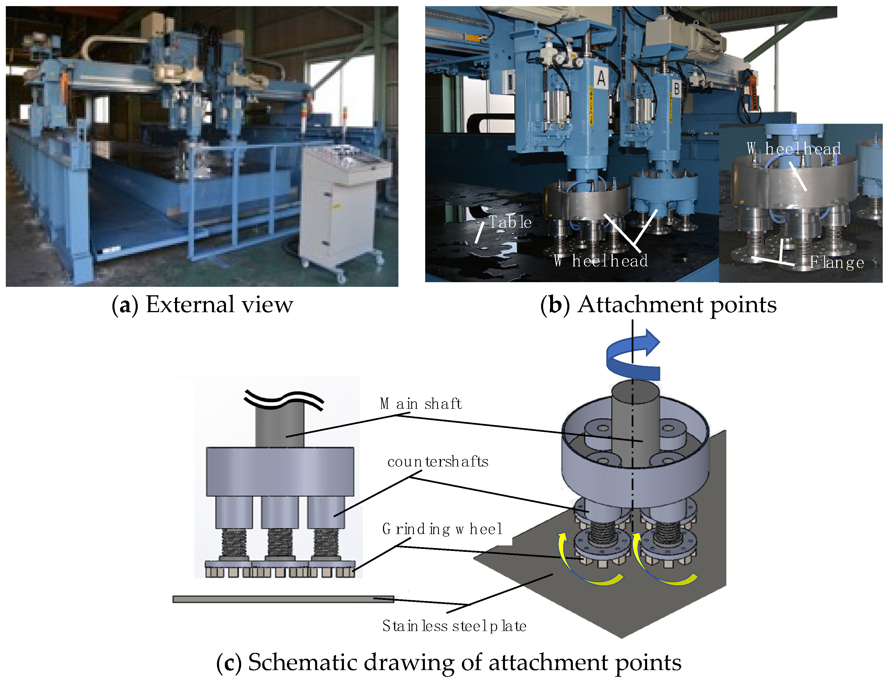
As no wet grinding machine for large stainless steel sheets currently exists, we developed a prototype based on an existing dry grinding machine. To determine the prototype specifications, we studied specifications such as spindle speed, grinding wheel feed rate, and working fluid supply. Figure 1 shows an external view of the developed wet grinding machine and the attachment points for the grinding wheels. The machine was built following the gantry style with a raised frame. The machine dimensions are 2800 mm (maximum height) × 4750 mm (maximum width) × 9260 mm (maximum length). The maximum size of the workpiece to be ground is 16 mm thick × 1524 mm wide × 6100 mm long. The machine is equipped with two main shafts, and each shaft has four countershafts. The countershafts are passively rotated by the active rotation that is transmitted by the gears of the main shafts, which are directly connected to the motor. The spindle speed can be increased from 39.5 to 395 rpm with a gear ratio of 1:1. The movement of the grinding wheel is implemented as epicyclic rotation, which reduces the unevenness of the finished surface and improves grinding efficiency. The number of main shafts to be used is selectable, and each can be controlled independently from a control box. The grinding wheel is fixed with an adhesive to a stainless steel disc (SUS430, JIS) with a diameter of 150 mm and a thickness of 2 mm. The grinding wheel head at the tip of the spindle is equipped with four flanges with a 150 mm diameter. As shown in Figure 2, a magnet is embedded in the flange, making it easy to detach the stainless steel disc jig to which the grinding wheel is attached, thus reducing the labor required to change the grinding wheel. The spindle speed, the feed rate of the gantry unit, and the feed rate of the grinding wheel head are controlled through an inverter. Moreover, the control box allows for the configuration of various settings. The gantry unit runs on a rack gear drive, with the gear shifting performed by an inverter. A motor-driven screw jack system drives the grinding wheel head. The feed rate of the gantry unit can be set from 0.01 to 0.5 m/s, and the feed rate of the grinding wheel head can be set from 0.01 to 0.2 m/s. The grinding solution uses tap water without mixing additives. The grinding fluid drains at a rate of approximately 3 L per minute from the center of the main shaft, as shown in Figure 2. The grinding fluid is filtered and recirculated. As only tap water is used, the waste treatment is less burdensome and the environmental impact is smaller than that of using chemicals. The grinding fluid also prevents thermal deformation and dust dispersal, removes the swarf, and reduces the processing heat. The pressing force of the grinding wheel is controlled by air pressure to provide an appropriate pressure and allow for grinding along the curvature of the material. The grinding wheel head pressure operates between 0.1 and 0.4 MPa.
2.2. Selecting a Grinding Wheel Experimentally
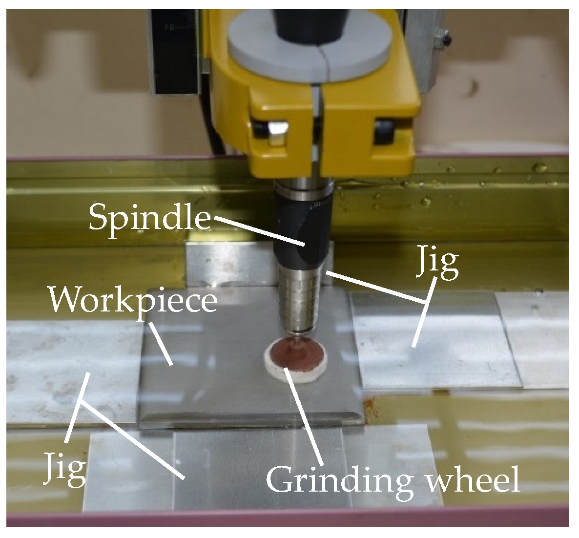
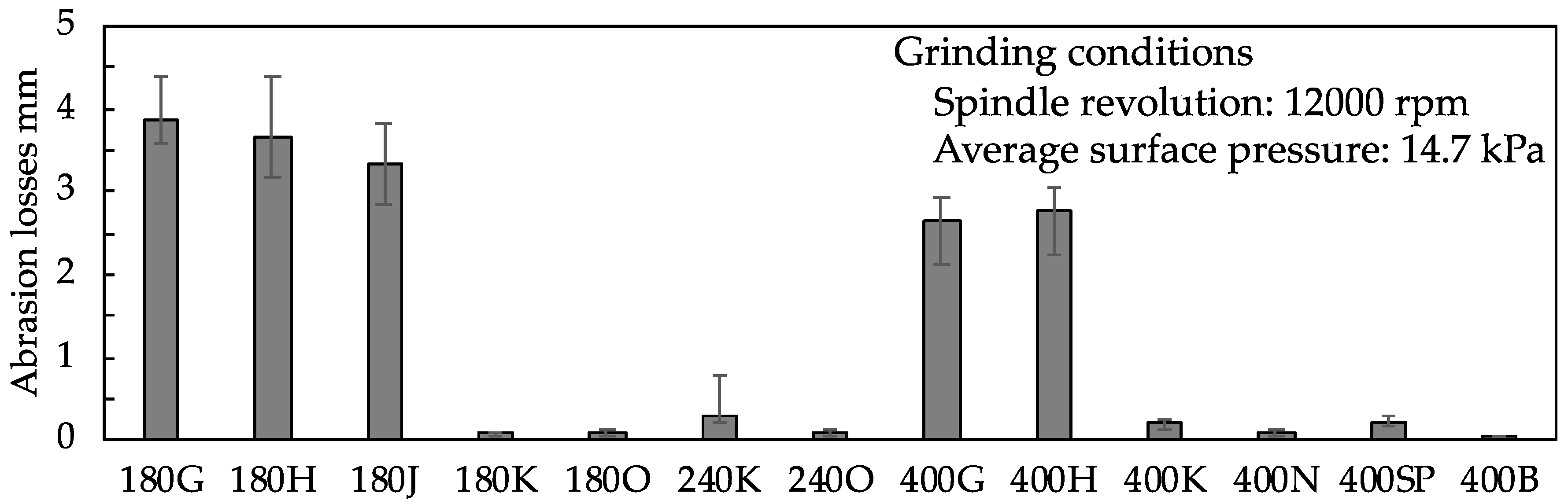
Figure 3 shows the machining part of the wet tabletop grinding equipment designed to select the optimum grinding wheel for the wet grinding of a stainless steel sheet. It serves as a model of the grinding wheel mounted on the large grinding machine, as shown in Figure 1. The grinding wheels used in the experiment were commercially available grinding wheels that were cut into a cylindrical shape with a diameter of approximately 25 mm and a thickness of approximately 5 mm. The grinding wheel was glued to the flange shaft, and the shaft was held using a collet chuck inside the spindle. The spindle was fixed to the stand of the grinding machine. The rotation speed of the spindle was set through the controller. A constant in-feed pressure was applied only in the z-axis direction of the table; thus, no motions along x- and y-axes were provided. This surface pressure was calculated by measuring the pressure with a three-component dynamometer installed on the table. The workpiece was stainless steel (SUS304, JIS). This steel sheet was fixed with a jig inside a water tank mounted on the table, while the tank was filled with sufficient tap water to immerse the surface of the steel sheet. The grinding time was set to 1 min. Each grinding wheel performance was evaluated in terms of the abrasion loss on the grinding wheel and the surface roughness of the steel sheet. The grinding conditions were set at a spindle speed of 12,000 rpm and an average surface pressure of 14.7 kPa along the z-axis. The dimensions of the workpiece were 80 × 80 × 8 mm. The surface roughness of the steel sheet was measured using a surface roughness measuring instrument (Mitutoyo SJ-410); the arithmetic average height of the assessed profile before grinding was Ra = 3.0 μm.
2.3. Hardness of Grinding Wheels
Table 1 lists the wheels used in the grinding and provides a short description of each wheel. White alundum was used as the abrasive grain. As a bonding agent, we used either vitrified, resin, or sponge bonds. For the sponge bond grinding wheels, we used acetanilide from polyvinyl alcohol (PVA) as the bonding agent. For the hardness and structure, we used the values provided by the grinding wheel manufacturer. The hardness ranged from G to O (JIS), and the structure was 9. To refer to the grinding wheels in a shorthand notation, we indicate the vitrified grinding wheels by grain size and the grade of hardness, and we classify the resin bond and sponge bond grinding wheels by grain size and the type of bonding agent (B or SP).
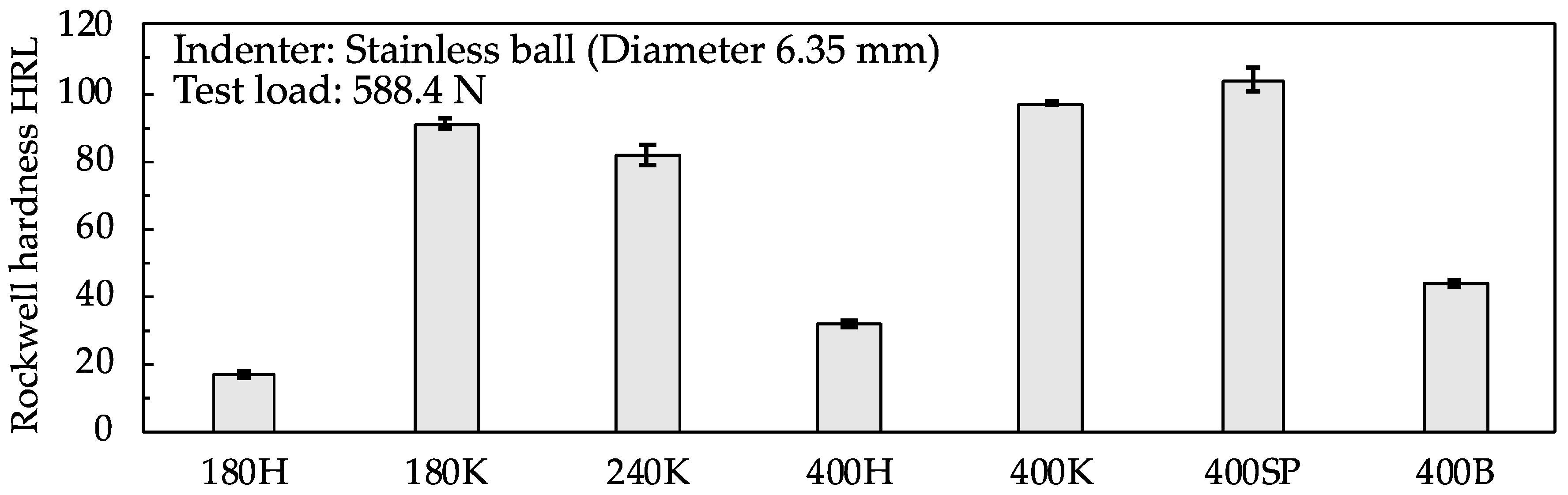
We performed the Rockwell hardness test on each grinding wheel because the sponge grinding wheels had no hardness value available in a specification sheet. The hardness measuring instrument was a handmade machine that was an improved version of the universal testing machine.
Figure 4 shows the Rockwell hardness measurements of the grinding wheels. A steel ball with a sphere diameter of 6.35 mm was used as the indenter, and the test load was set at 588.4 N. The hardness of the sponge grinding wheel was approximately 100 HRL. This value corresponded to the hardness of K for a vitrified bond. The hardness of the resin-bond grinding wheel (approximately 40 HRL) was slightly higher than the degree of hardness (400H) of the vitrified bond.
We set two conditions for selecting a grinding wheel: it had to be capable of wet grinding and have an adequate hardness to prevent self-sharpening loading. We used the grinding wheels shown in Table 1 on a stainless steel sheet to find the grinding wheels with the least abrasion loss and the smallest surface roughness.
3. Results and Discussion
3.1. Abrasion Losses and Abrasion Conditions of Grinding Wheel
Figure 5 shows the average abrasion loss of the grinding wheel thickness after grinding. We conducted three trials for each type of grinding wheel and then calculated the average abrasion loss from the abrasion losses of the three grinding wheels. Before grinding, the thickness of the grinding wheel was 5 mm. For the vitrified grinding wheels, the abrasion loss was the highest with hardness values of G, H, and J and the smallest with a hardness value of K. Regarding the abrasion condition of the grinding wheels during grinding, those with hardness values of G, H, and J wore out immediately after the start of machining. The resin bond and sponge grinding wheels exhibited less abrasion loss than the vitrified grinding wheels.
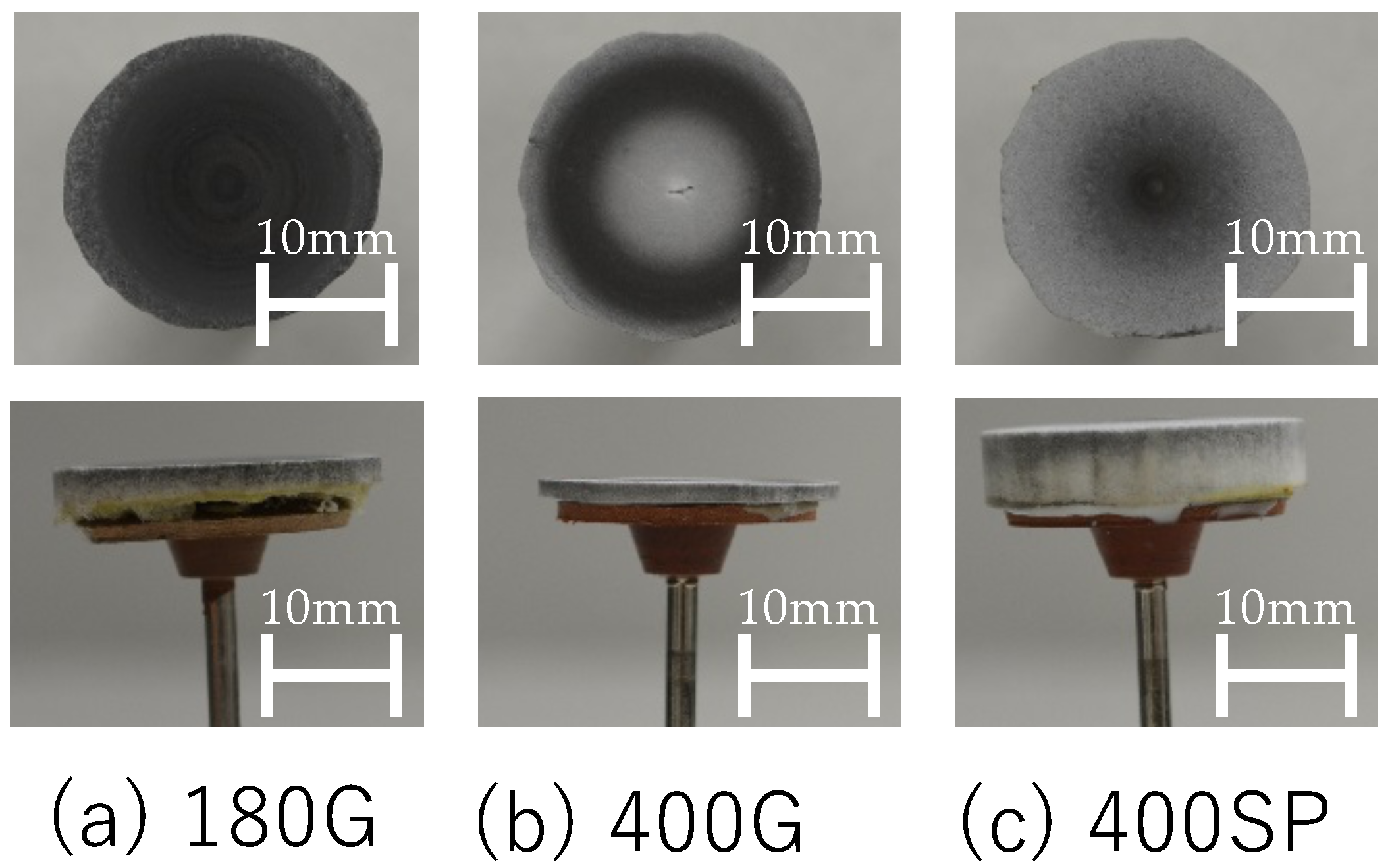
Figure 6 shows the conditions of each wheel—180G, 400G, and 400SP—after machining. After grinding, the surface of the grinding wheel was almost level. The grinding wheels were worn down almost evenly because of the uniform application of the indentation load. Their original thickness of the 180G and 400G grinding wheels changed substantially. In contrast, the thickness of the 400SP wheel was approximately the same as before machining. Moreover, the entire surface of the grinding wheel was stained gray. The staining of the surface suggested the adhesion of the swarf to the pores.
Based on the abrasion condition of the vitrified grinding wheels with lower hardness values, we hypothesize that releasing occurred because the hardness was substantially low for the machining conditions. Furthermore, the vitrified, sponge, and resin bond grinding wheels with higher hardness values experienced loading due to the accumulation of swarf adhering to the pores. The abrasion loss on the grinding wheels used for grinding was governed by the hardness and did not depend on the type of bonding agent or the size of the abrasive grains.
3.2. Comparison of Loss Ratios and Surface Properties of Steel Sheet
The grinding ratio is commonly used as an abrasion resistance indicator of a grinding wheel and is the value obtained by dividing the workpiece removal volume by the abrasion volume of the grinding wheel consumed during the grinding. In these experiments, the workpiece removal volume was minimal and difficult to measure. In this paper, the grinding ratio is the amount of improvement in surface roughness divided by the abrasion losses of the grinding wheel, which is called the loss rate. The amount of improvement in surface roughness was calculated by subtracting the arithmetic average height of the assessed profile after grinding from the arithmetic average height of the assessed profile before grinding. The abrasion loss on the grinding wheel used the values shown in Figure 4.
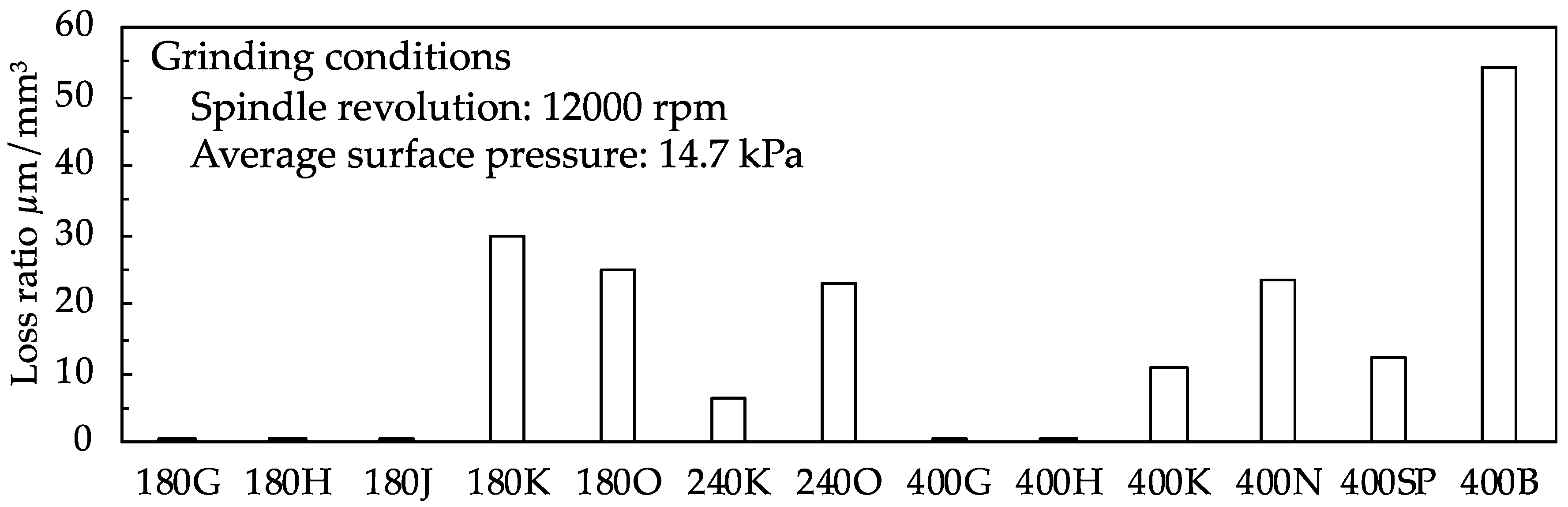
Figure 7 shows the loss ratio of each wheel. For the vitrified grinding wheels, the loss ratio was the smallest for the wheels with the lowest hardness values. Moreover, the ratio was the highest for grinding wheels with the highest hardness values. When the grain size was different but the hardness was similar, the loss ratio did not show much difference. To the extent that the loss ratio could be interpreted as the grinding performance, the wheels with the highest hardness values had the best grinding performance. The loss ratio of the 400SP wheel was almost the same as the 400K wheel. Moreover, the 400B wheel presented the highest loss ratio. The amount of improvement in surface roughness was slightly less than that for the sponge wheel; however, it was affected by the difference in the abrasion loss on the grinding wheels.
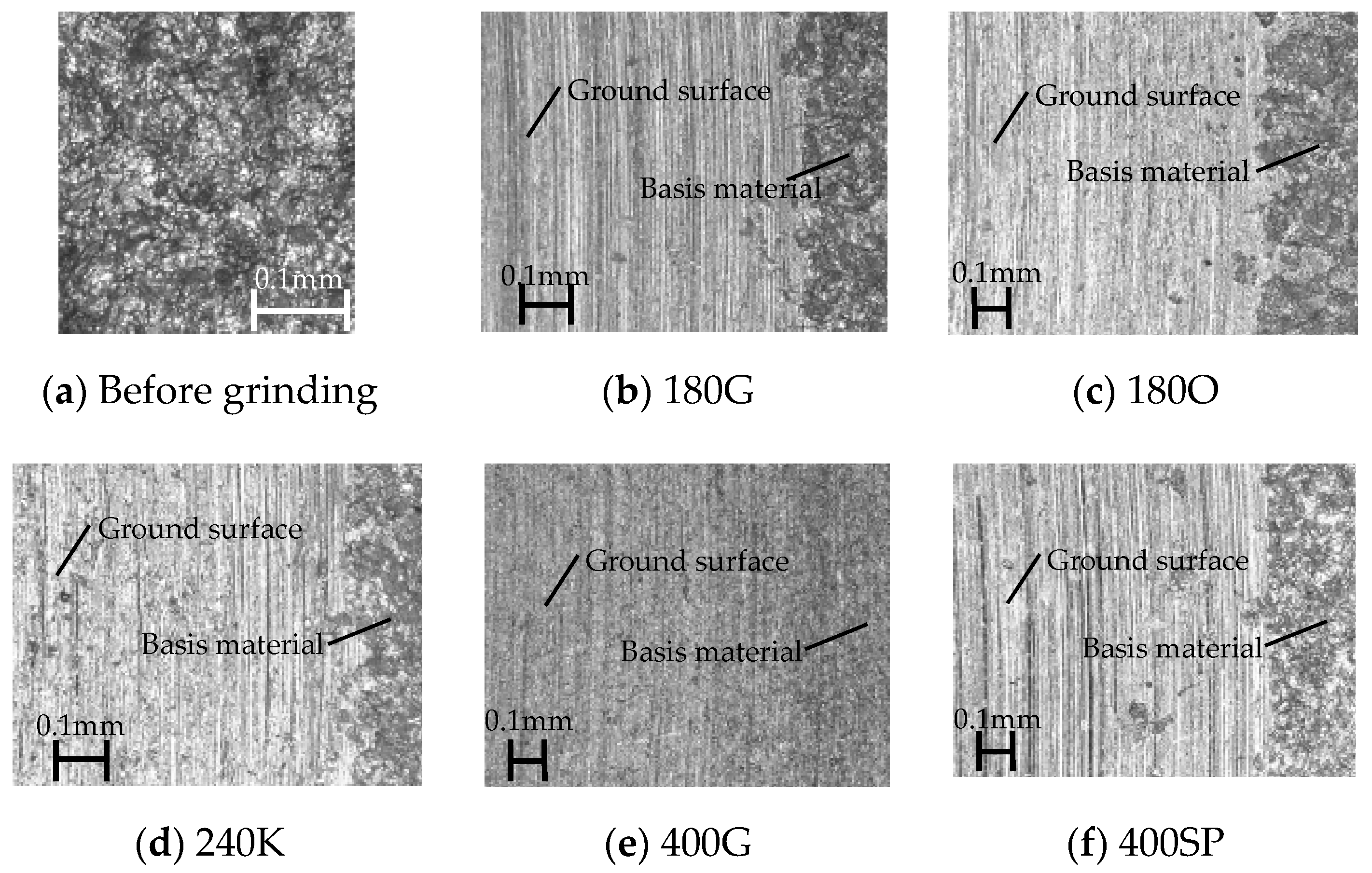
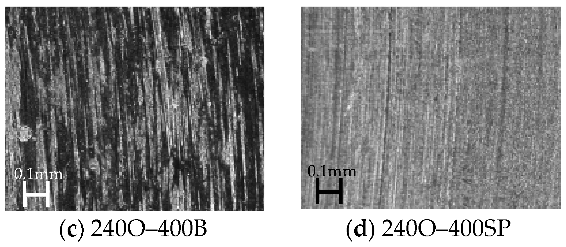
Figure 8 shows the surface properties of the stainless steel sheet. A digital microscope (Keyence, VHX-500) was used to observe the surface of the steel sheet. Figure 8a shows the surface condition of the stainless steel sheet before grinding. This steel sheet surface had a No. 1 finish and was cleaned with acid after heat treatment. In other words, the surface was etched with acid. Figure 8b–f shows the surface conditions after grinding for the 180G, 180O, 240K, 400G, and 400SP wheels, respectively. The observation point was set near the outer circumference of the wheel. Scratch marks from the abrasive grains were clearly visible on the surfaces machined with the 180G, 180O, 240K, and 400SP wheels. Clear boundaries were present between the areas subjected to grinding and those that were not. Moreover, few scratch marks were present on the surfaces machined with the 400G wheels.
3.3. Surface Properties of Steel Sheet after Rough Grinding and Semi-Finish Grinding
The results outlined above suggest that it is possible to grind a steel sheet with only one grinding wheel. However, it was challenging to select a single grinding wheel with a low abrasion loss that could satisfy the requirement of obtaining the arithmetic average height of the assessed profile of 0.3 μm or less before buffing. Therefore, we selected multiple candidates from the grinding wheels, as shown in Table 1, and performed grinding using these wheels. To maintain low costs, we imposed a constraint that only two grinding wheels could be used: one for rough grinding and another for semi-finish grinding.
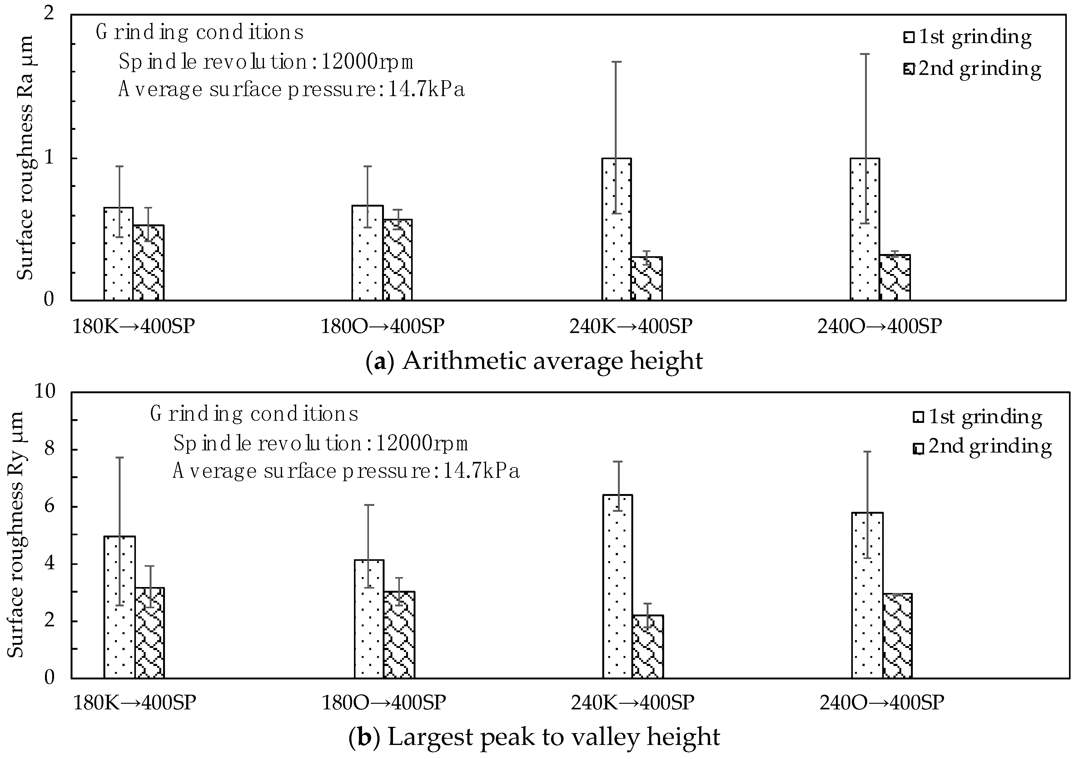
First, for rough grinding, the 180K, 180O, 240K, and 240O grinding wheels, which had large amounts of shavings on the etched surface, were selected as candidates. After rough grinding with this grinding wheel, semi-finished grinding was performed using the 400SP wheel. Figure 9 shows the arithmetic average height (Ra) and the largest peak to valley height (Ry) of the assessed profile of the steel sheet after grinding it with the four candidate wheels for rough grinding and the 400SP wheel for semi-finish grinding. When rough grinding was performed, the grinding wheels with smaller grain sizes minimized the surface roughness. Subsequently, when semi-finish grinding was performed, the grinding wheel with a larger grain size minimized the surface roughness. When machining to a #180 finish, the in-feed was very deep, creating deep scratches in the steel sheet. Additionally, the 400SP wheel could not be machined to the depth of the scratches. The grinding wheel combinations that could reach a surface roughness of approximately Ra = 0.3 μm were the 240K–400SP and 240O–400SP combinations.
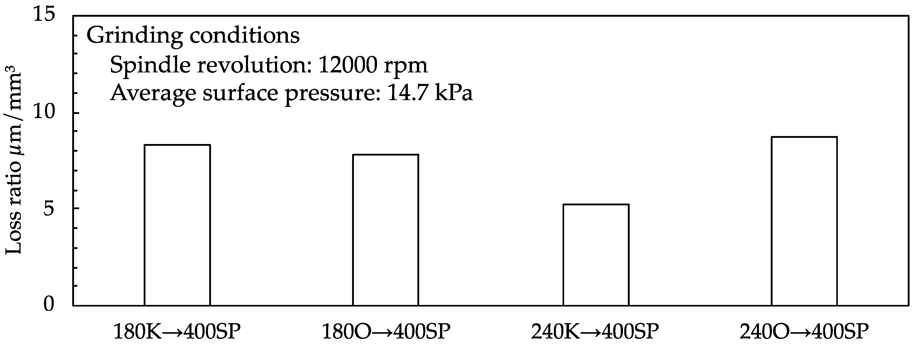
Figure 10 shows the loss ratios for rough and semi-finish grinding. To calculate the loss ratio, we first obtained the arithmetic average height of the assessed profile when grinding with the 400PVA rough grinding wheel. Subsequently, we divided this number by the added abrasion loss, which we obtained by summing the abrasion loss on the rough grinding wheel and the abrasion loss on the 400PVA wheel. Even though the 240K–400SP combination improved the surface roughness the most, it had the lowest loss ratio at 5.19. This was because the added abrasion loss was high. The 240O–400SP combination had the highest loss ratio at 8.70, and its surface roughness was Ra = 0.319 μm, similar to the 240K–400SP combination. Here, the added abrasion loss was 0.09 mm. By comparing the loss ratio, it was possible to estimate the combination in which this value became smaller.
Figure 11 shows the condition of the steel sheet after grinding with the 180K–400SP and 240K–400SP combinations. The 180K–400SP combination left scratch marks on the steel sheet surface, while the 240K–400SP combination left the surface virtually scratch-free. Scratch marks should be removed by re-buffing, which means that another round of grinding is required. If the scratch marks are very deep, the product is considered to be defective. The loss ratio of the 180K–400SP combination was higher than 8. We decided to exclude it from the selection based on the final finish condition, which showed scratch marks.
Subsequently, to select a grinding wheel for semi-finish grinding, the steel sheet was ground using the 400K, 400N, 400B, and 400PVA wheels after rough grinding with the 240O wheel.
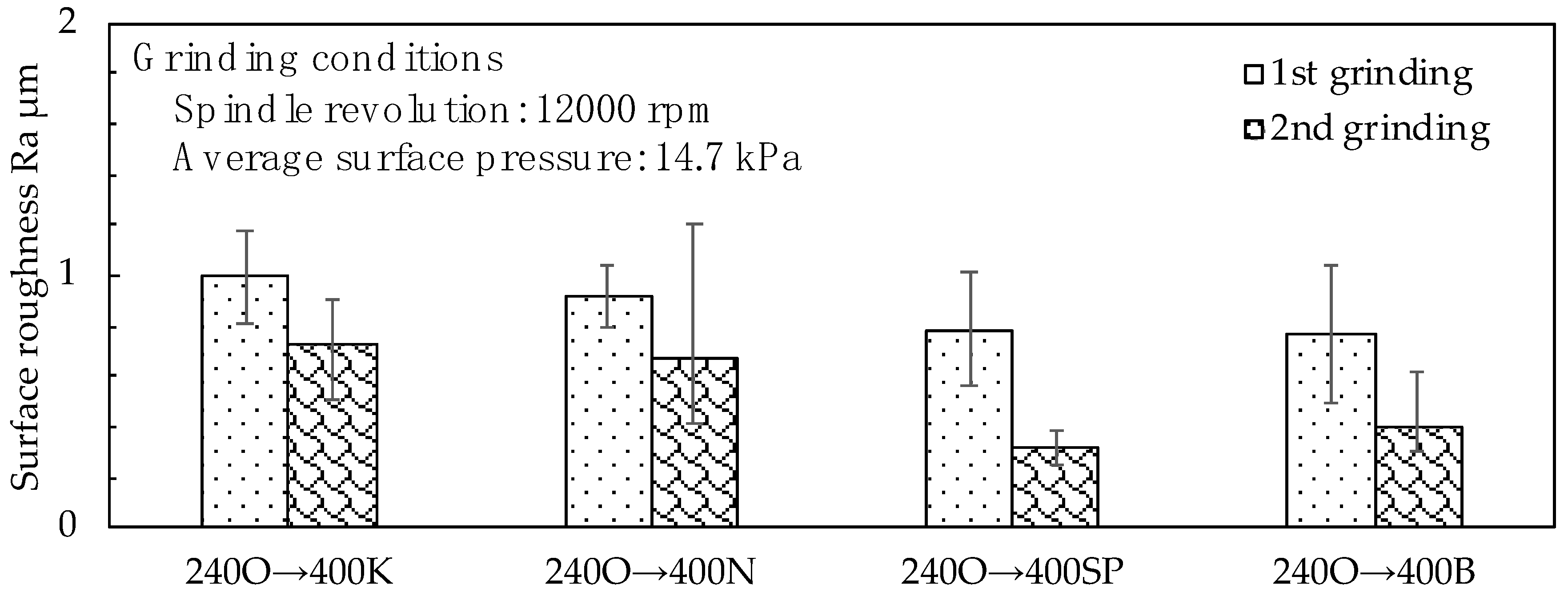
Figure 12 shows the arithmetic average height of the assessed profile of the steel sheet after the semi-finish grinding. The surface roughness of the 400K and 400N wheels was higher than that of the 400B and 400PVA wheels. The smallest value was obtained for the 240O–400SP combination.
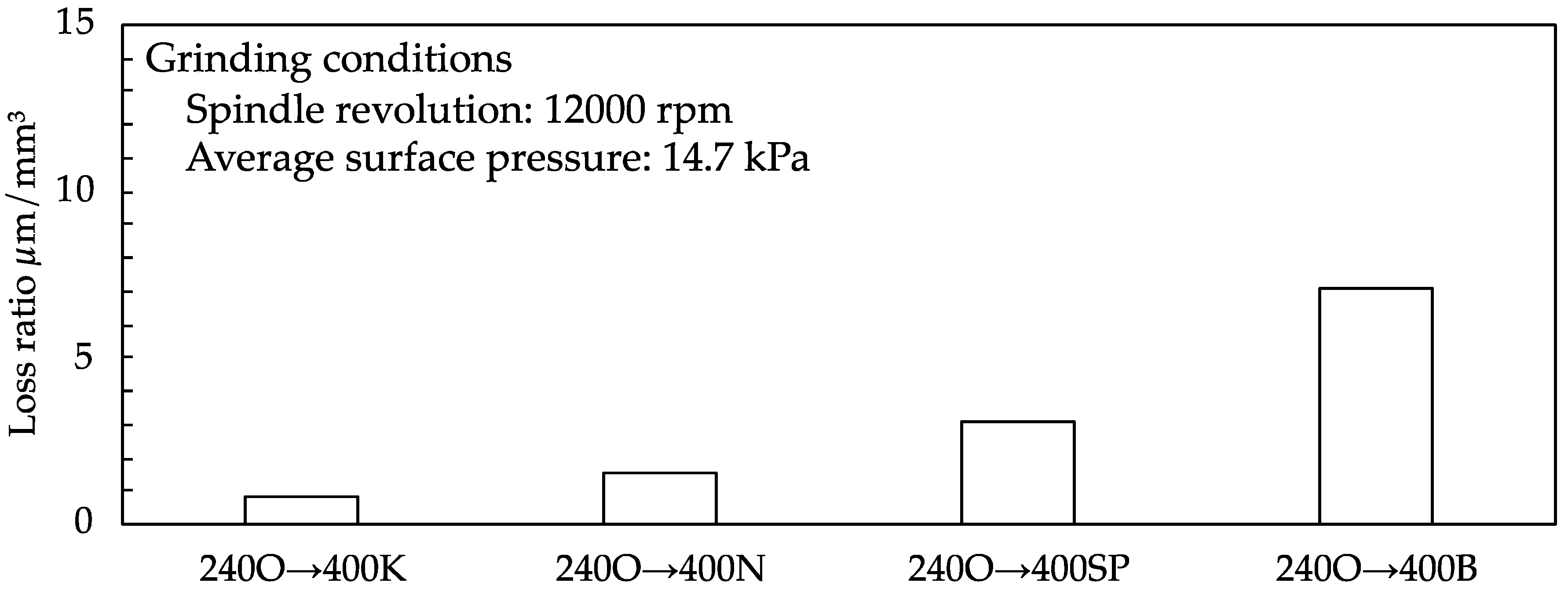
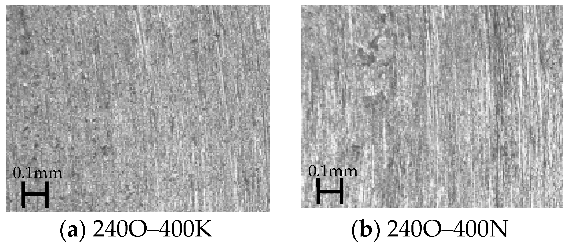
Figure 13 and Figure 14 show the loss ratios and steel sheet surface conditions, respectively. To calculate the loss ratio of each semi-finish grinding wheel, we first obtained the arithmetic average height of the assessed profile when grinding with the wheel after rough grinding with the 240O wheel. After that, we divided this number by the added abrasion loss, which we obtained by summing the abrasion loss on the 240O wheel and the abrasion loss on the tested grinding wheel. The 400B wheel exhibited a small abrasion loss and presented the highest loss ratio. However, comparing the steel sheet surfaces after grinding, the 400B wheel left several scratch marks. Moreover, the vitrified grinding wheels left almost no scratch marks on the machined surface, and the loss ratios were smaller than those of the other wheels.
For coarse finishing, it appears that grinding wheels with higher hardness values are suitable for machining an etched surface. In contrast, for semi-finishing, grinding wheels with lower hardness values are suitable for machining a nascent surface. Meanwhile, unlike the resin bond grinding wheels, the sponge grinding wheels left no visible scratch marks on the grinding surface, and the loss ratio was approximately half the value of the 400B wheel.
The improvement in surface roughness was considered to be due to the multi-pore structure and elasticity of the PVA grinding wheel. In the case of a multi-pore structure, it is presumed that loading due to chips of stainless steel sheet is unlikely to occur, prevents an increase in frictional resistance during grinding, and has the effect of moderate wear. Since the PVA grinding wheel is an organic binder and has a multi-pore structure, when it is pressed against a work material, the abrasive grains are pushed into the binder and behave so that the abrasive grain cutting edges are aligned. Therefore, deep scratches are unlikely to occur on a ground surface.
3.4. Grinding Using a Large Wet-Grinding Machine
Guided by the results obtained above, we used the large wet-grinding machine to grind large steel sheets. The size of the workpiece was 1219 mm × 2438 mm × 8 mm. The grinding conditions were changed to a spindle speed of 150 rpm, a surface pressure of 0.2 MPa, and a lateral speed of 15.4 mm/s. The grinding wheel had no dressing.
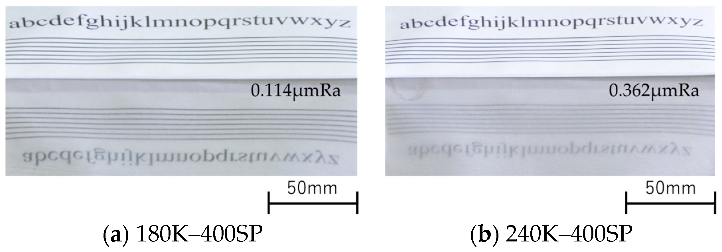
Figure 15 shows the surface condition and surface roughness when grinding with the 180K–400SP and 240K–400SP combinations. The number of grinding sessions was two for rough grinding and 10 for semi-finish grinding. The figure shows the characteristics reflected on both steel sheet surfaces. However, there were various fine scratches on the steel sheet surface, and these scratches could not be removed even after ten grinding sessions with the 400SP wheel. Such scratches are prone to remain even after buffing.
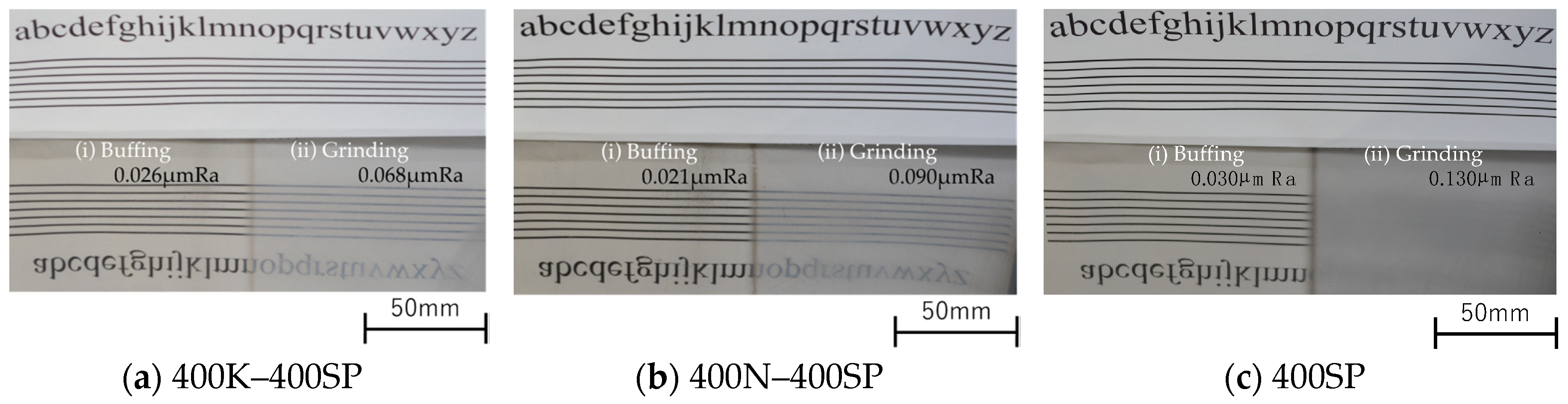
Figure 16 shows the surface condition and roughness when grinding with the 400K–400SP, 400N–400SP, and 400SP combinations; the condition after buffing is also shown. The number of grinding sessions was set to 3 for the 400K, 400N, and 400SP wheels. Buffing was performed until the steel sheet was glossy, and no scratches were found on the steel sheet surface after buffing. The surface roughness was also very low. When only the 400SP wheel was used, 15 grinding sessions were required to achieve a similar grinding surface. Though it required more and longer grinding sessions, the No. 1 substrate was machined, and the surface roughness was low, with almost no fine scratches observed. Considering the machining quality, efficiency, and cost, grinding with various #400 wheels was found to be superior when using a single 400SP wheel.
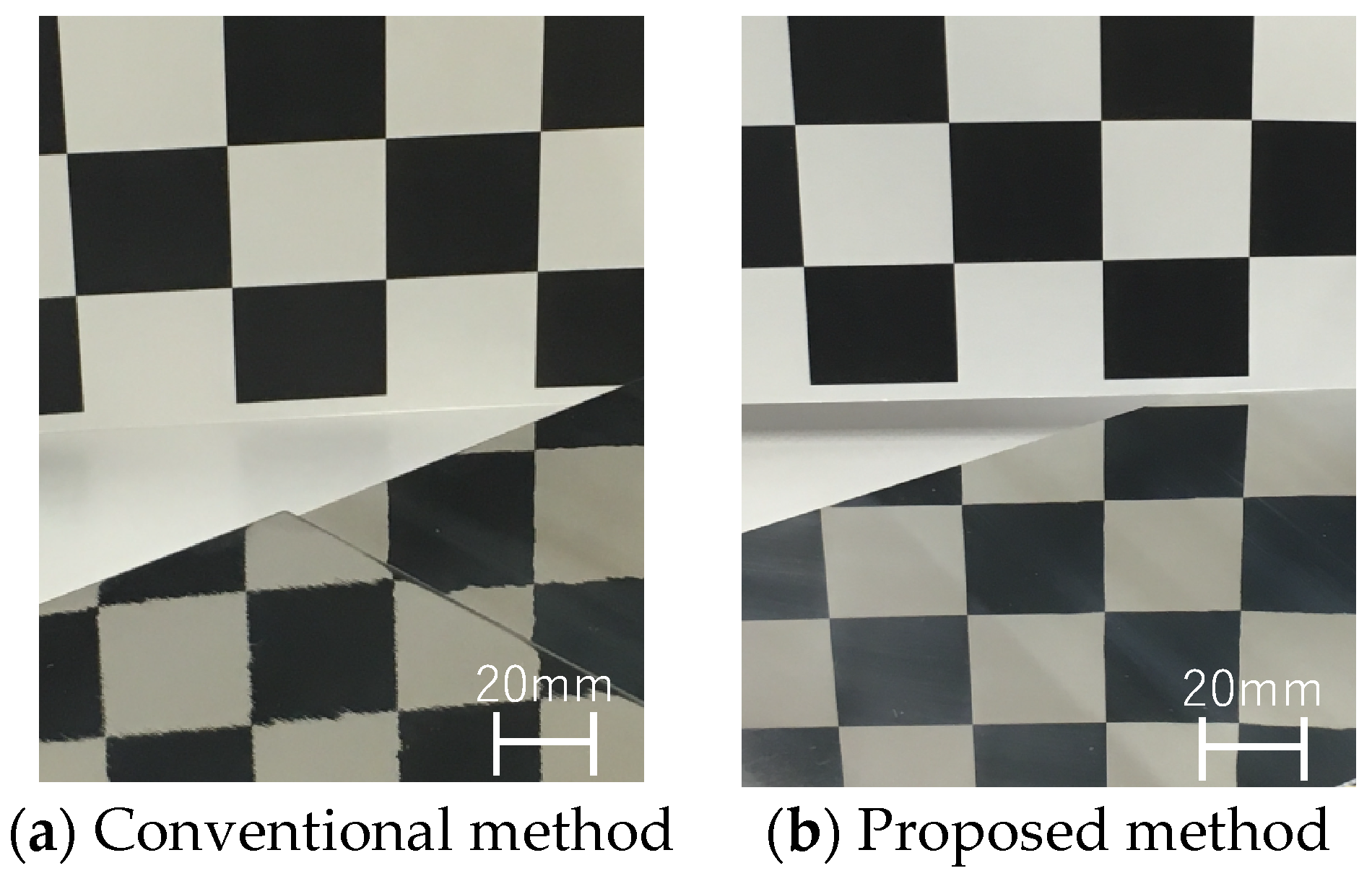
Figure 17 shows the machined surfaces under the conventional method (dry machining) with a flap wheel and the proposed method (wet machining) with the 400SP wheel. In both cases, gingham checks were reflected on the steel sheet surface. Note that the checks in Figure 17a appear distorted. Moreover, the checks in Figure 17b are clearly visible. The proposed method appears to have caused less distortion on the steel sheet surface than the conventional method.
4. Conclusions
The study aimed to develop a practical application of wet grinding and polishing technology for large stainless steel sheets. Specifically, we evaluated wet grinding technology for machining the substrate of No. 1 finished stainless steel sheet to a ground surface. The following results were obtained:
- A wet grinding machine for large stainless steel sheets was developed.
- The PVA grinding wheel was suitable for grinding stainless steel sheets.
- The PVA grinding wheel provided a good surface condition with an arithmetic average height of the assessed profile of Ra = 0.3 μm. After this grinding, the Ra parameter was 0.03 μm when buffing was performed.
- No scratch marks or distortions were present on the steel sheet surface, and the machining quality was excellent.
- The use of wet processing suppressed the generation of dust and prevented atmospheric dispersal, thereby improving the working environment.
- In this paper, we described the effectiveness of the PVA grinding wheel in the grinding of stainless steel sheets. We are continuing our experiments to explain this effectiveness more logically.
Author Contributions
Data curation, A.M.; Methodology, A.M. and A.T.; Investigation, A.M. and A.T.; Writing—original draft, A.M.; Writing—review & editing, A.M. and A.T. All authors have read and agreed to the published version of the manuscript.
Funding
This research received no external funding.
Conflicts of Interest
The authors declare no conflict of interest.
References
- Malkin, S.; Guo, C. Grinding Technology; Theory and Application of Machining with Abrasives; Industrial Press Inc.: New York, NY, USA, 2008. [Google Scholar]
- Li, G.F.; Wang, L.S.; Yang, L.B. Multi-parameter optimization and control of the cylindrical grinding process. J. Mater. Process. Technol. 2002, 129, 232–236. [Google Scholar] [CrossRef]
- Chatterjee, S.; Rudrapati, R.; Kumar pal, P.; Nandi, G. Experiments, analysis and parametric optimization of cylindrical traverse cut grinding of aluminium bronze. Mater. Today Proc. 2018, 5, 5272–5280. [Google Scholar] [CrossRef]
- Gupta, R.; Shishodia, K.S.; Sekhon, G.S. Optimization of grinding process parameters using enumeration method. J. Mater. Process. Technol. 2001, 112, 63–67. [Google Scholar] [CrossRef]
- Pi, V.N.; The, P.Q.; Khiem, V.H.; Huong, N.N. Cost optimization of external cylindrical grinding. Appl. Mech. Mater. 2013, 312, 982–989. [Google Scholar] [CrossRef]
- Pi, V.N.; Tung, L.A.; Hung, L.X.; Ngoc, N.C. Experimental Determination of Optimum Replaced Diameter in Surface Grinding Process. J. Environ. Sci. Eng. 2017, 5, 85–89. [Google Scholar]
- Rana, P.; Lalwani, D.I. Parameters optimization of surface grinding process using Modified ε constrained Differential Evolution. Mater. Today Proc. 2017, 4, 10104–10108. [Google Scholar] [CrossRef]
- Pandiyan, V.; Caesarendra, W. Tegoeh Tjahjowidodo, and Gunasekaran Praveen, Predictive Modelling and Analysis of Process Parameters on Material Removal Characteristics in Abrasive Belt Grinding Process. Appl. Sci. 2017, 7, 363. [Google Scholar] [CrossRef]
- Hecker, R.L.; Liang, S.Y. Predictive modeling of surface roughness in grinding. Int. J. Mach. Tools Manuf. 2003, 43, 755–761. [Google Scholar] [CrossRef]
- Omura, K.; Kunioka, S.; Furukawa, M. Product Development on Market Trends of Stainless Steel and Its Future Prospects. Nippon Steel Tech. Rep. 2010, 99, 9–19. [Google Scholar]
- Syreyshchikova, N.V.; Guzeev, V.I.; Ardashev, D.V.; Pimenov, D.Y.; Patra, K.; Kapłonek, W.; Nadolny, K. A Study on the Machinability of Steels and Alloys to Develop Recommendations for Setting Tool Performance Characteristics and Belt Grinding Modes. Materials 2020, 13, 3978. [Google Scholar] [CrossRef]
- Sankaranarayanan, G.; Shireesha, K.; Kennedy, A.X. Taguchi analysis in optimization of belt grinding of stainless steel 304. Int. J. Mach. Mach. Mater. 2009, 5, 41–59. [Google Scholar]
- Rokosz, K.; Solecki, G.; Mori, G.; Fluch, R.; Kapp, M.; Lahtinen, J. Effect of Polishing on Electrochemical Behavior and Passive Layer Composition of Different Stainless Steels. Materials 2020, 13, 3402. [Google Scholar] [CrossRef] [PubMed]
- Kim, T.; Lee, H. Preliminary Study on Fluidized Bed Chemical Mechanical Polishing (FB-CMP) Process for Stainless Steel 304 (SS304). Micromachines 2020, 11, 705. [Google Scholar] [CrossRef] [PubMed]
- Edyta, L.; Pawel, L.; Ginter, N. Electrochemical Polishing of Austenitic Stainless Steels. Materials 2020, 13, 2557. [Google Scholar]
- Muhannad, A.O.; Eanna, M.; Barry, O.; Inam, U.A.; Dermot, B. Laser Polishing of Additive Manufactured 316L Stainless Steel Synthesized by Selective Laser Melting. Materials 2019, 12, 991. [Google Scholar]
- Fang-Jung, S.; Chih-Cheng, H. Surface finishing of hardened and tempered stainless tool steel using sequential ball grindings, ball burnishing and ball polishing process on a machining centre. J. Mat. Proc. Technol. 2008, 205, 249–258. [Google Scholar]
- Ohmori, H.; Katahira, K.; Komotori, J.; Mizutani, M. Functionalization of stainless steel surface through mirror-quality finish grinding. CIRP Ann. Manuf. Technol. 2008, 57, 545–549. [Google Scholar] [CrossRef]
- Xiaokai, H.; Zhitang, S.; Weili, L.; Fei, Q.; Zefang, Z.; Haibo, W. Chemical mechanical polishing of stainless steel foil as flexible substrate. Appl. Surf. Sci. 2012, 258, 5798–5802. [Google Scholar]
- Kao, P.; Hocheng, H. Optimization of electrochemical polishing of stainless steel by grey relational analysis. J. Mat. Proc. Technol. 2003, 140, 255–259. [Google Scholar] [CrossRef]
- Jakobsson, K.; Mikoczt, Z.; Skerfving, S. Deaths and tumours among workers grinding stainless steel: A follow up. Occup. Environ. Med. 1997, 54, 825–829. [Google Scholar] [CrossRef] [Green Version]
- Cashdollar, K.L. Overview of dust explosibility characteristics. J. Loss Prev. Process. Ind. 2000, 13, 183–199. [Google Scholar] [CrossRef]
Figure 1.
Developed wet grinding machine and attachment points for the grinding wheels.

Figure 2.
Magnet attachment and grinding fluid drain.

Figure 3.
Wet tabletop grinding equipment.

Figure 4.
Rockwell hardness measurements of grinding wheels.

Figure 5.
Average abrasion loss of the grinding wheel thickness after grinding.

Figure 6.
Conditions of the 180G, 400G, and 400SP wheels after machining.

Figure 7.
Loss ratio of each wheel.

Figure 8.
Surface properties of the stainless steel sheet (a) Before grinding (b) 180G (c) 180O (d) 240K (e) 400G (f) 400SP.
Figure 8.
Surface properties of the stainless steel sheet (a) Before grinding (b) 180G (c) 180O (d) 240K (e) 400G (f) 400SP.

Figure 9.
Arithmetic average height and largest peak to valley height of the assessed profile of the steel sheet after grinding.
Figure 9.
Arithmetic average height and largest peak to valley height of the assessed profile of the steel sheet after grinding.

Figure 10.
Loss ratios for rough and semi-finish grinding.

Figure 11.
Condition of the steel sheet after grinding with the 180K–400SP and 240K–400SP combinations.
Figure 11.
Condition of the steel sheet after grinding with the 180K–400SP and 240K–400SP combinations.

Figure 12.
Arithmetic average height of the assessed profile of the steel sheet after the semi-finish grinding.
Figure 12.
Arithmetic average height of the assessed profile of the steel sheet after the semi-finish grinding.

Figure 13.
Loss ratios of the steel sheet after the semi-finish grinding.

Figure 14.
Steel sheet surface conditions.


Figure 15.
Surface condition and surface roughness when grinding with the 180K–400SP and 240K–400SP combinations.
Figure 15.
Surface condition and surface roughness when grinding with the 180K–400SP and 240K–400SP combinations.

Figure 16.
Surface condition and roughness when grinding with the 400K–400SP, 400N–400SP, and 400SP combinations.
Figure 16.
Surface condition and roughness when grinding with the 400K–400SP, 400N–400SP, and 400SP combinations.

Figure 17.
Machined surfaces under the conventional method with a flap wheel (a) and the proposed method with the 400SP wheel (b).
Figure 17.
Machined surfaces under the conventional method with a flap wheel (a) and the proposed method with the 400SP wheel (b).


Table 1.
Wheels used in the grinding.
| Label | Grain Size | Bond | Grade |
|---|---|---|---|
| 180G | #180 | Vitrified | G |
| 180H | #180 | Vitrified | H |
| 180J | #180 | Vitrified | J |
| 180K | #180 | Vitrified | K |
| 180O | #180 | Vitrified | O |
| 240K | #240 | Vitrified | K |
| 240O | #240 | Vitrified | O |
| 400G | #400 | Vitrified | G |
| 400H | #400 | Vitrified | H |
| 400K | #400 | Vitrified | K |
| 400N | #400 | Vitrified | N |
| 400SP | #400 | Sponge | - |
| 400B | #400 | Resinoid | D |
Publisher’s Note: MDPI stays neutral with regard to jurisdictional claims in published maps and institutional affiliations. |
© 2020 by the authors. Licensee MDPI, Basel, Switzerland. This article is an open access article distributed under the terms and conditions of the Creative Commons Attribution (CC BY) license (http://creativecommons.org/licenses/by/4.0/).
Share and Cite
MDPI and ACS Style
Mizobuchi, A.; Tashima, A. Optimization of Wet Grinding Conditions of Sheets Made of Stainless Steel. J. Manuf. Mater. Process. 2020, 4, 114. https://0-doi-org.brum.beds.ac.uk/10.3390/jmmp4040114
AMA Style
Mizobuchi A, Tashima A. Optimization of Wet Grinding Conditions of Sheets Made of Stainless Steel. Journal of Manufacturing and Materials Processing. 2020; 4(4):114. https://0-doi-org.brum.beds.ac.uk/10.3390/jmmp4040114
Chicago/Turabian StyleMizobuchi, Akira, and Atsuyoshi Tashima. 2020. "Optimization of Wet Grinding Conditions of Sheets Made of Stainless Steel" Journal of Manufacturing and Materials Processing 4, no. 4: 114. https://0-doi-org.brum.beds.ac.uk/10.3390/jmmp4040114