Article

Dexel-Based Simulation of Directed Energy Deposition Additive Manufacturing

1
Institute of Production Engineering and Machine Tools (IFW), Leibniz Universität Hannover, 30823 Garbsen, Germany
2
Cluster of Excellence PhoenixD (Photonics, Optics, and Engineering—Innovation Across Disciplines), Leibniz Universität Hannover, 30167 Hannover, Germany
*
Author to whom correspondence should be addressed.
J. Manuf. Mater. Process. 2021, 5(1), 9; https://0-doi-org.brum.beds.ac.uk/10.3390/jmmp5010009
Submission received: 1 December 2020 / Revised: 18 December 2020 / Accepted: 6 January 2021 / Published: 11 January 2021
(This article belongs to the Special Issue Advances in Modelling of Machining Operations)

Abstract

:
Additive manufacturing is typically a flexible alternative to conventional manufacturing processes. However, manufacturing costs increase due to the effort required to experimentally determine optimum process parameters for customized products or small batches. Therefore, simulation models are needed in order to reduce the amount of effort necessary for experimental testing. For this purpose, a novel technological simulation method for directed energy deposition additive manufacturing is presented here. The Dexel-based simulation allows modeling of additive manufacturing of varying geometric shapes by considering multi-axis machine tool kinematics and local process conditions. The simulation approach can be combined with the simulation of subtractive processes, which enables integrated digital process chains.

1. Introduction

In recent years, additive manufacturing (AM) has gained interest in the designing and manufacturing of prototypes within the aerospace, automotive and medical industries. Additive manufacturing is characterized by flexibility in design regarding new geometry or functionality and both individual and custom fabrication.
Efficient process planning of an additive manufacturing process becomes increasingly important due to decreasing batch sizes and the higher level of individualization. Since experimental process planning is time-consuming and cost-intensive, a simulation-based process design has the potential to improve process planning continuously. It enables the prevention of manufacturing errors and optimizes the process design. In this way, costs for production rejects and reworking can be reduced. In literature, numerous studies on the simulation of additive manufacturing deal with the simulation of thermo-mechanical properties such as temperature or residual stresses. Only a small amount of research papers investigate the simulation of geometric aspects within additive processes. However, detailed knowledge regarding form and shape results in various benefits, especially when dealing with hybrid manufacturing, including additive as well as cutting processes. With a precise geometric prediction, process planning for the cutting process can be remarkably improved. In actual implementation, different discretization methods can be employed to simulate the deposited material. In this paper, a Dexel-based simulation method for additive manufacturing is investigated. It is capable of varying the shape of the deposited material dynamically according to local process conditions of the deposited layer and can be used for five-axis processes as well. Dexels are a data structure used in the simulation of changing workpiece shapes in subtractive manufacturing. They are popular because of their memory effectiveness and good performance. A brief description is included in the following.

2. State of the Art

Approaches for the simulation of additive manufacturing, found in existing literature, can be categorized into two groups. The first group is defined as the simulation of thermomechanical processes, e.g., heat supply and heat dissipation, which can be used to predict state variables such as temperature and residual stress. With these simulation models, the process and the interaction between process control variables and process boundary conditions can be explained, for example, to predict thermo-mechanical effects [1,2,3]. Normally, the finite element (FE) or volume of fluid (VOF) methods are used for this kind of simulation task.
The second group includes geometrical simulation models which are used to predict the geometric shape of additive layers or components. Their main purpose is to detect shape errors or possible collisions. In this context, one approach is to calculate the influence of material properties or thermo-mechanical parameters on the geometrical shape of the deposited structure based on FE methods [1,4,5,6]. In this case, the results have high accuracy and show the aggregate state of the material. However, due to the intricate modeling approach, process parameters such as feed rate or travel velocity cannot be varied directly in the simulation alongside the process. Additionally, the calculation of an FE simulation as a surface-based deformable geometric model is very time consuming and, thus, cannot be applied to the entire process. Consequently, these simulations are commonly used to investigate short process segments under specific process conditions.
The application of analytical methods such as constructive solid geometry (CSG), voxel or Dexel [7] as a discrete model is another approach for geometric simulations. These methods allow a much faster calculation and simulation than FE models. Thus, they have more potential to be used for the simulation of the whole manufacturing process. However, a CSG model might consist of a large number of Boolean operations between primitive basic elements such as spheres, cylinders and cubes. Therefore, this approach may lead to a significant increase in simulation time for representing the workpiece geometry [8]. In contrast, for modeling the tool geometry, only single primitives, e.g., cylinders, are needed. For this reason, CSG models are suitable to represent the tool geometry [9]. Aremu et al. presented a voxel-based method for the generation of lattices, which is suitable for additive manufacturing of workpieces with an inner lattice structure. Furthermore, the variation of the cell properties within a lattice structure is addressed [10]. Dexel-based simulation methods, as shown in Figure 1, consist of a grid of line segments which can be regarded as parallel nails or rods, whereby length can be varied to change the overall shape.
Dexels are commonly used for the simulation of subtractive processes, for instance, turning, milling and grinding [11]. In contrast to CSG, the Dexel model is also suitable for objects with interior regions as lattices or pores [12].
He et al. and Sun et al. used a Dexel-based method to simulate the geometry in powder-based additive manufacturing. It was shown that the Dexel method has high potential for the simulation of additive processes. The constant layer volume was simulated by merging the Dexels using a constantly defined virtual tool to make a swept volume (converted into a Tri-Dexel model) as a geometry of the additive layer [13,14]. Because the height of the layers is assumed to be constant, this method is suitable for powder-bed-based AM processes only, such as selective laser melting (SLM). In contrast, in directed energy deposition (DED), AM such as wire and arc additive manufacturing (WAAM) or laser glass deposition (LGD), the tool path or the local variation of geometry influence the height and width of the deposited material. Therefore, it is not possible to define a constant virtual tool and a constant resulting swept volume for the entire path. Table 1 provides a summary of the latest literature on the geometric simulation of additive processes.
Current technology illustrates several different approaches for the geometric simulations of additive manufacturing processes. Many studies deal with the simulation of powder-based additive manufacturing such as SLM. Simulation approaches of DED processes have been researched less in literature. A possible reason for this might be the high requirements for simulation when it comes to complex kinematics, as is the case concerning the usage of industrial robots. Furthermore, it can be stated that the geometric adaption of deposited material during the process has not yet been taken into account. However, this is necessary in order to consider the influence of process parameters and tool path on the deposit geometry.

3. Objective and Approach

This paper aims to present a novel method for a Dexel-based geometric simulation of DED processes. For this purpose, different simulation approaches of manufacturing processes are compared. Based on that, a suitable methodology for a Dexel-based representation of the deposited material is developed. Afterward, the method for determining the geometry of the deposited material is investigated, whereby the influences of process control parameters and tool path are taken into account. Finally, application of the presented simulation method is shown using a wire arc additive manufacturing process as an example.

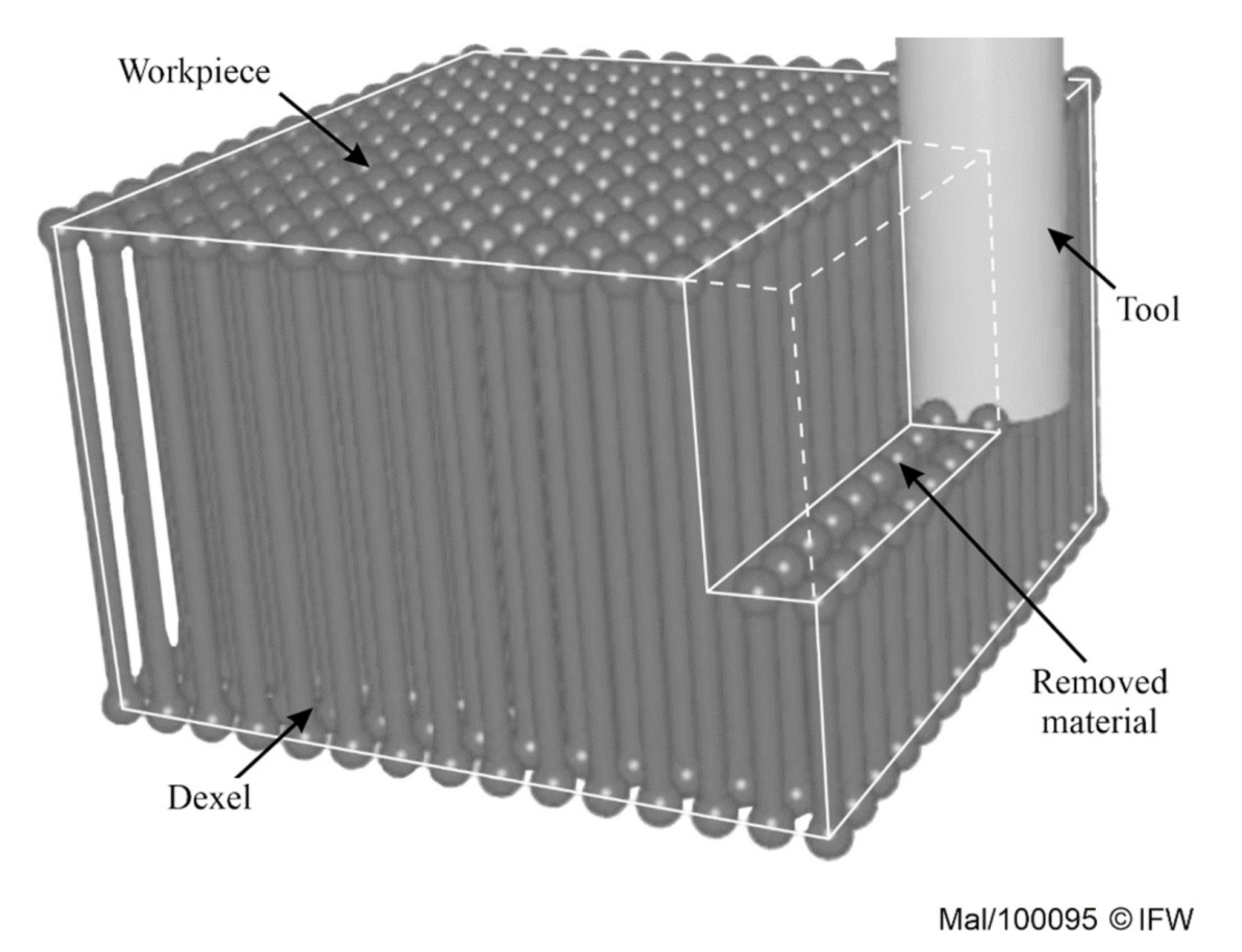
4. Tri-Dexel-Based Simulation Method

As shown by current technology, Dexel models are commonly applied in subtractive process simulations. In this paper, a method for the geometric modeling of DED additive manufacturing processes is presented. For this purpose, a numerically controlled (NC) Dexel-based simulation is used to calculate the material deposition.

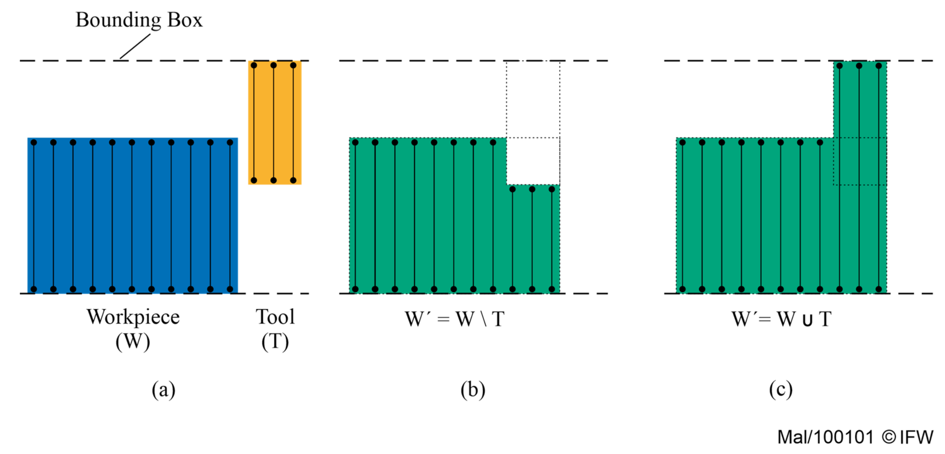
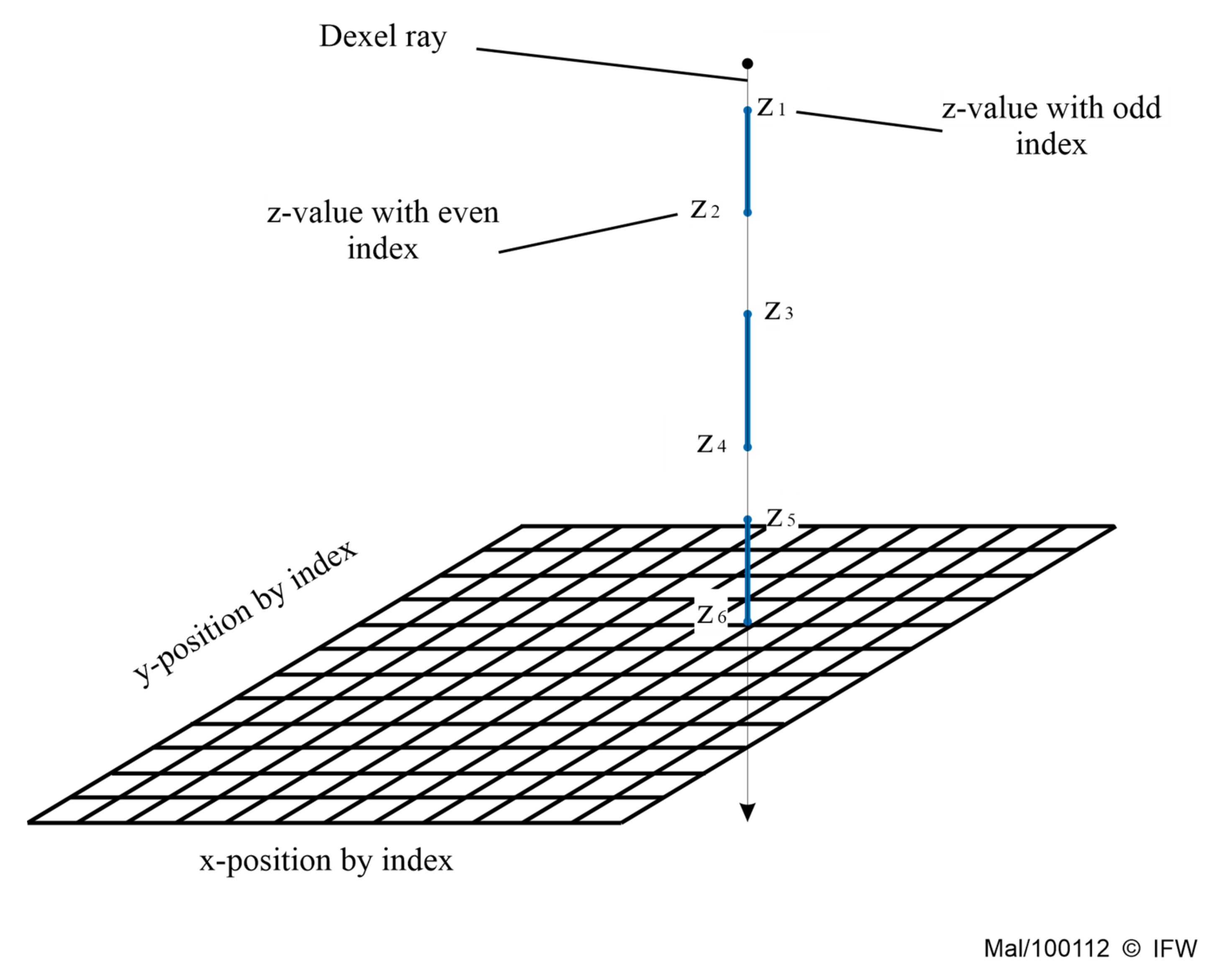
4.1. Material Deposition into Dexel Models

The major concept in common approaches of subtractive process simulation is a time-discrete movement with successive calculation of engagement between a tool and a workpiece. In the simulation of subtractive processes, the resulting workpiece geometry is calculated by subtracting the tool geometry from the initial workpiece (Figure 2a). The presented approach uses Dexel to represent the workpiece shape. According to Denkena et al., the cutting operation of Dexels can be distinguished into three cases: cut, divide and erase [17].
In contrast to subtractive processes, the simulation of additive processes has no physical tool shape which can be used for calculation of the engagement. Thus, a virtual tool is needed which describes the shape of material deposition. Depending on the process, the virtual tool can be described, e.g., by the shape of the fluid droplet or the affected zone of a melting process and has to be manipulated later according to the cooling behavior and fluid dynamics of the deposited material. If the geometry of the cooled material deposit is known, for instance, through analytical or empirical modeling or by looking up tables, this geometry can also be used as a virtual tool. This is faster because no cooling behavior has to be considered.
Figure 2. Algebraic operations: (a) initial situation; (b) intersection; (c) union.
Jmmp 05 00009 g002
Expressed in algebraic terms of sets or CSG terms respectively, the subtractive process can be described by the set difference of the set of points W representing the workpiece and the set T representing the tool, or more precisely, the area that the tool crossed within the time step (Figure 2b). Thus, in each time step, an operation W = W \ T is performed. In additive processes, the resulting set is the set union, W = W T (Figure 2c).
To implement this in parallel to cutting (cut, divide and erase), three further operations are necessary: lengthen, unite and create. Since each operation requires distinction of many cases, another approach is used: the complement of sets. This significantly reduces additional cases and can also be used with existing implementations, if applied to the whole model.
The calculation of material deposition using complementation consists of three steps (Figure 3). In the first step, the complement of the workpiece is calculated (Figure 3b). In the second step, the subtraction between the virtual tool and the surrounding space around the workpiece is carried out (Figure 3c). In the last step, the complement of the geometry of the second step is calculated, which results in the final geometry, including the substrate and the deposited material (Figure 3d).
Expressed in algebraic terms, when the complement of A is notated as Ac, according to De Morgan’s laws, it results in:
A \ B c = A c B
Thus, with A = W c and B = T , it leads to the following equation:
W c \ T c = W T
The significant advantage of using the complement is that only one simple operation has to be added, as described in the following.
Figure 3. Calculation steps for material deposition and transformation of the virtual tool shape into workpiece. Upper row: Calculation steps for a single Dexel line. Lower row: Sequence of calculation steps for the entire Dexel model. (a) Initial situation; (b) complement of workpiece; (c) subtraction of virtual tool; (d) complement; (e) resulting union of workpiece and deposited material with Dexels.
Jmmp 05 00009 g003
A memory structure for storing a single Dexel consists of the position data (x,y) and a description of the distribution of material at this position. The position data are usually given by a two-dimensional index in the grid of parallel Dexels. The material information as a list of start- and end-points alternates along a Dexel ray. Since the x and y components of the coordinates within one Dexel are constant, these points can each be represented by individual numerical z-values. Thus, the internal information about the intervals which consists of material is given by the parity of the start- and end-points along the corresponding line of the Dexel.
Figure 4 shows an example of the representation of a Dexel with three segments. When observing the Dexel line from positive infinity to negative infinity, reaching the first z-value represents entering material (odd). The next intersection represents the exit of the material (even). Both steps are repeated until the last point along the line is reached. If the parity of the number of hits is reversed, material changes into non-material and vice versa, which represents the complement described above. This can be achieved by adding two points at the boundaries of the examined area. In summary, material addition can be achieved by changing the parity of the number of hits and then cutting and removing the changing parity.

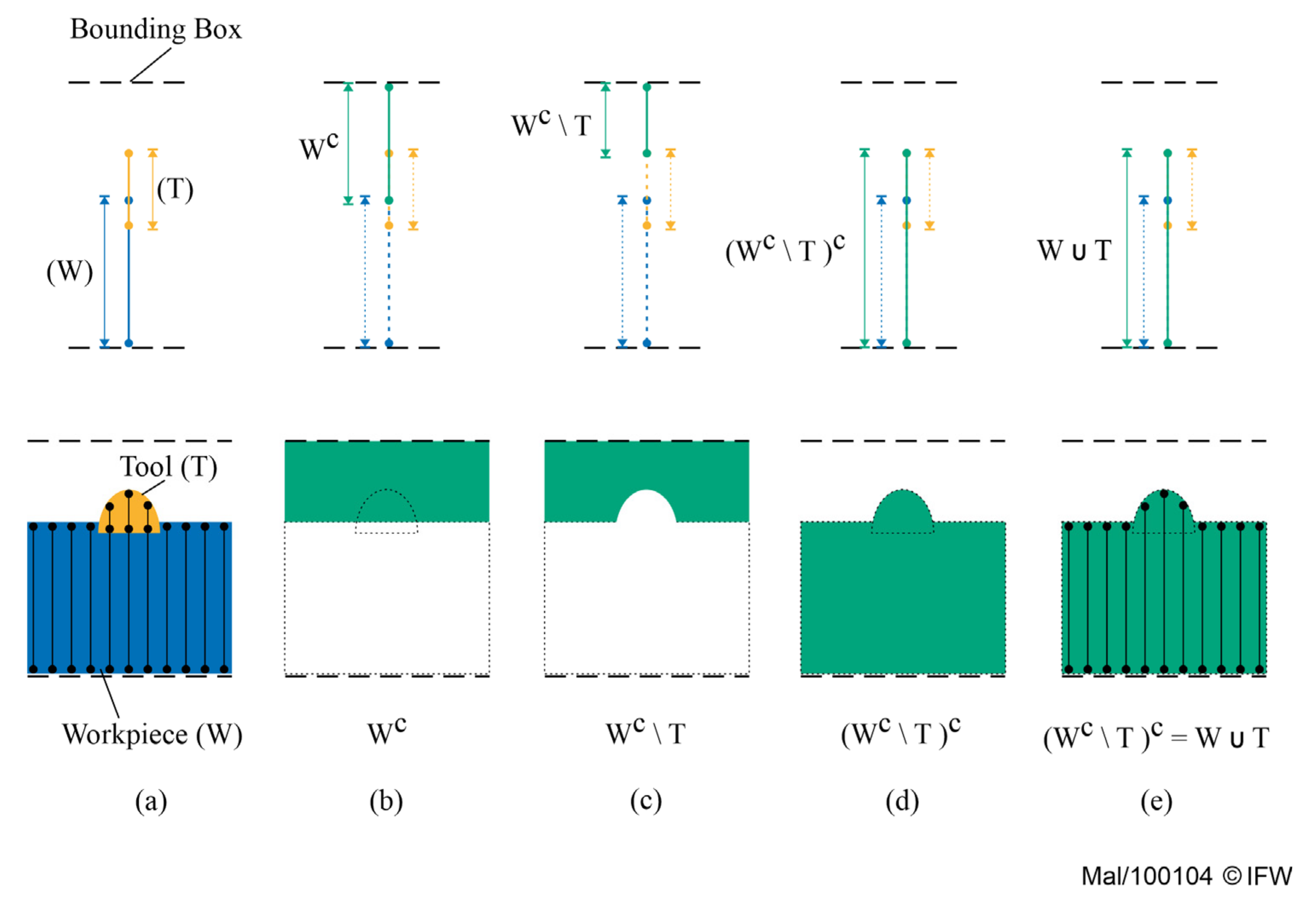
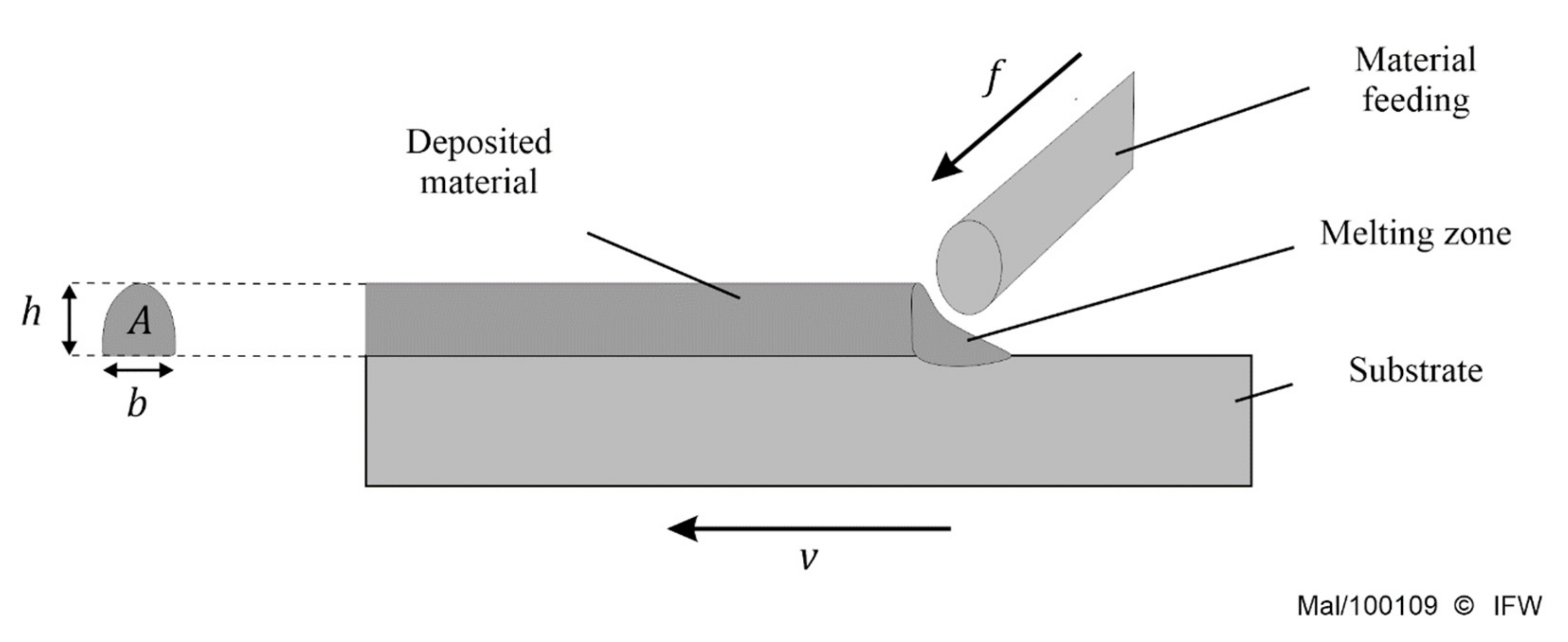
4.2. Determining the Shape of the Virtual Tool

In most subtractive processes, the shape of the tool is known and the volume of the removed material can be calculated in advance for each time step. However, in additive processes, the virtual tool strongly depends on the substrate shape and properties at the location of deposition. This means that the shape of the deposited material must be changed according to the process conditions. The local process conditions, for instance, tool path or process parameters, lead to a variation in the geometry of deposited material which influences, the height h and the width b of the deposited layer. Therefore, a non-constant virtual tool is needed to simulate the sweep volume as deposited material during the process.
In the DED and especially in wire- or fiber-based processes, the volume of deposited material can be mathematically determined by utilizing the correlation between the feed rate of material f and the travel velocity v (Figure 5).
From the volume constancy follows the equation to calculate the theoretical cross-section area A of the deposited material per unit length, where D is the diameter of fed material in the form of wire or fiber.
A = π f D 2 4 v
By using the cross-section model from Equation (3) for the calculation of the virtual tool form, the volume of the deposited material according to the movement of the multi-axis machine can be modeled. The geometrical shape of the material deposition can be varied by means of height and width. Apart from the process parameters feed rate f and travel velocity v , other process factors such as material properties under consideration of the process temperature must be taken into account.
The theoretical material transfer can be calculated for local changes to the planned path, where the travel velocity changes. Thus, the additive process can be simulated within process planning. After the implementation of the simulation method in the software IFW CutS [9], two example simulations were conducted. The first simulation presents additive simulation with directional change of the tool path, in which the travel velocity slows down and accelerates (Figure 6a). The second simulation shows a two-layer linear weld seam and a change in shape of the deposited material due to the variation of the ratio between the feed rate and the travel velocity (Equation (3)) in infeed and outfeed zones (Figure 6b).

4.3. Extension Capability

In order to design the model of the virtual tool more precisely, the shape or the ratio between the width and height of the applied material should be taken into account. This strongly depends on temperature. Another advantage of using Dexel for the simulation is that further information such as temperature values can be stored for each Dexel. This means that the shape of the tool, which can be determined by viscosity and wetting angle, can be adjusted. Thus, the temperature change over time and the cooling rate can be taken into account.

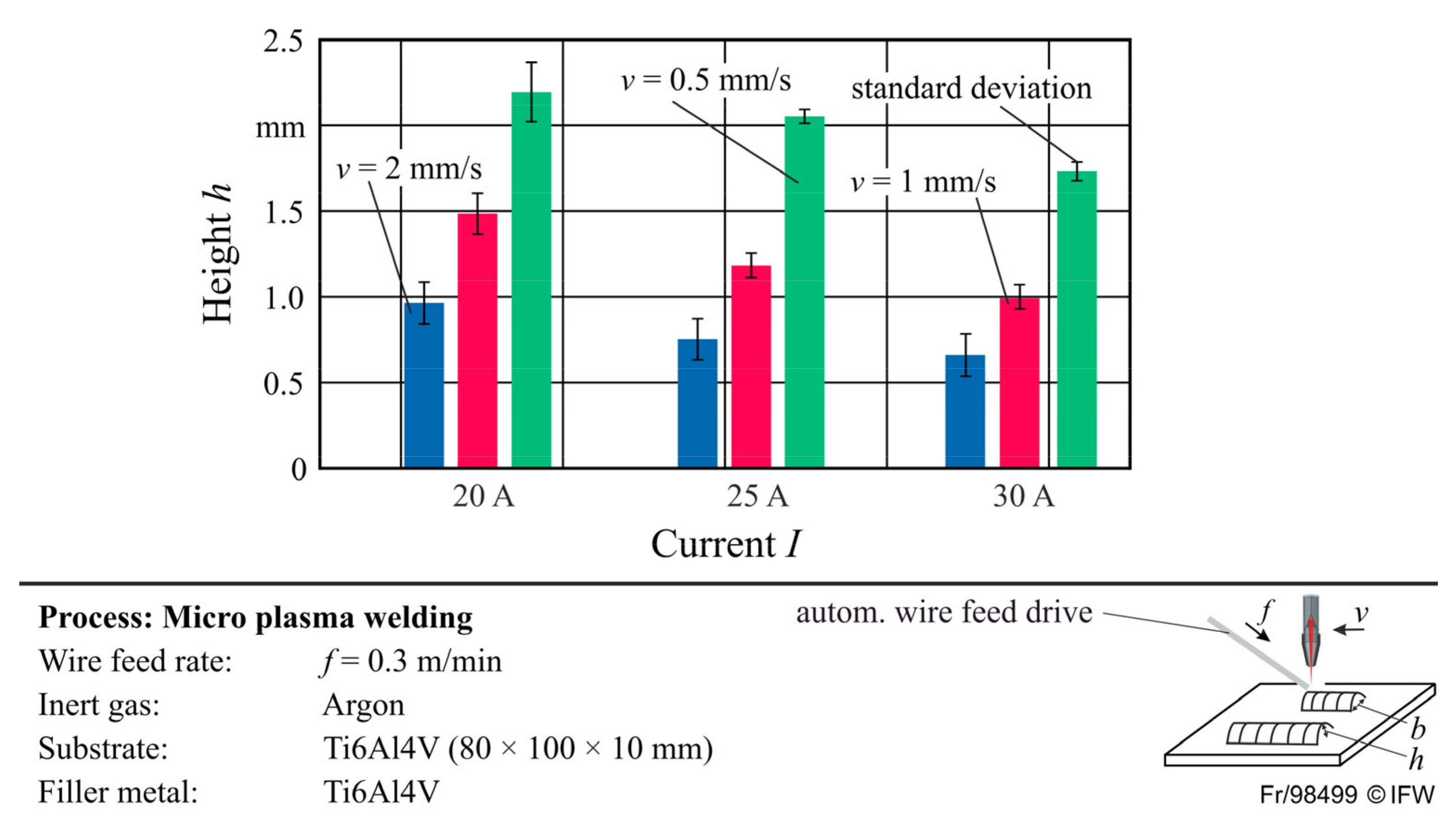
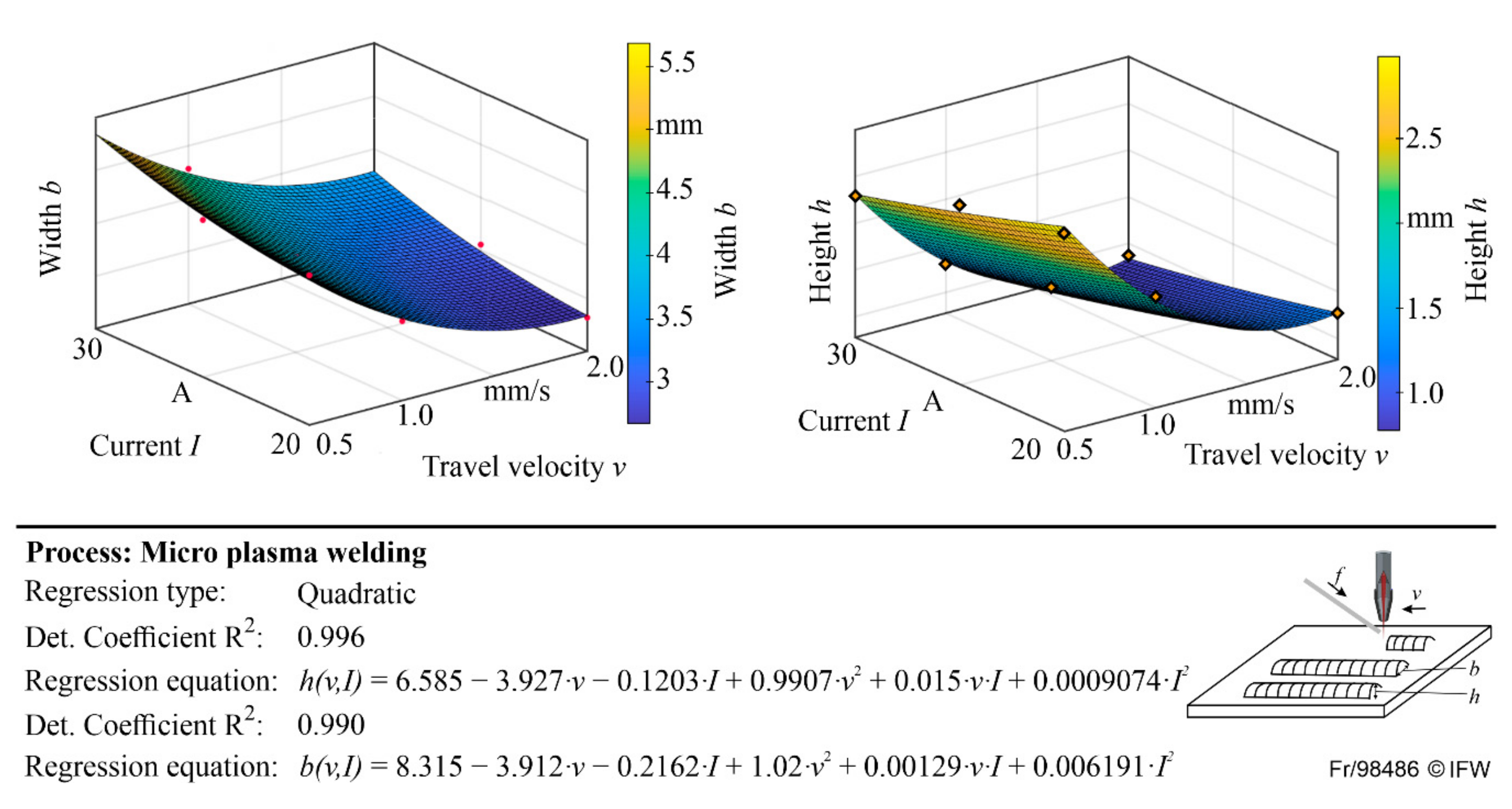
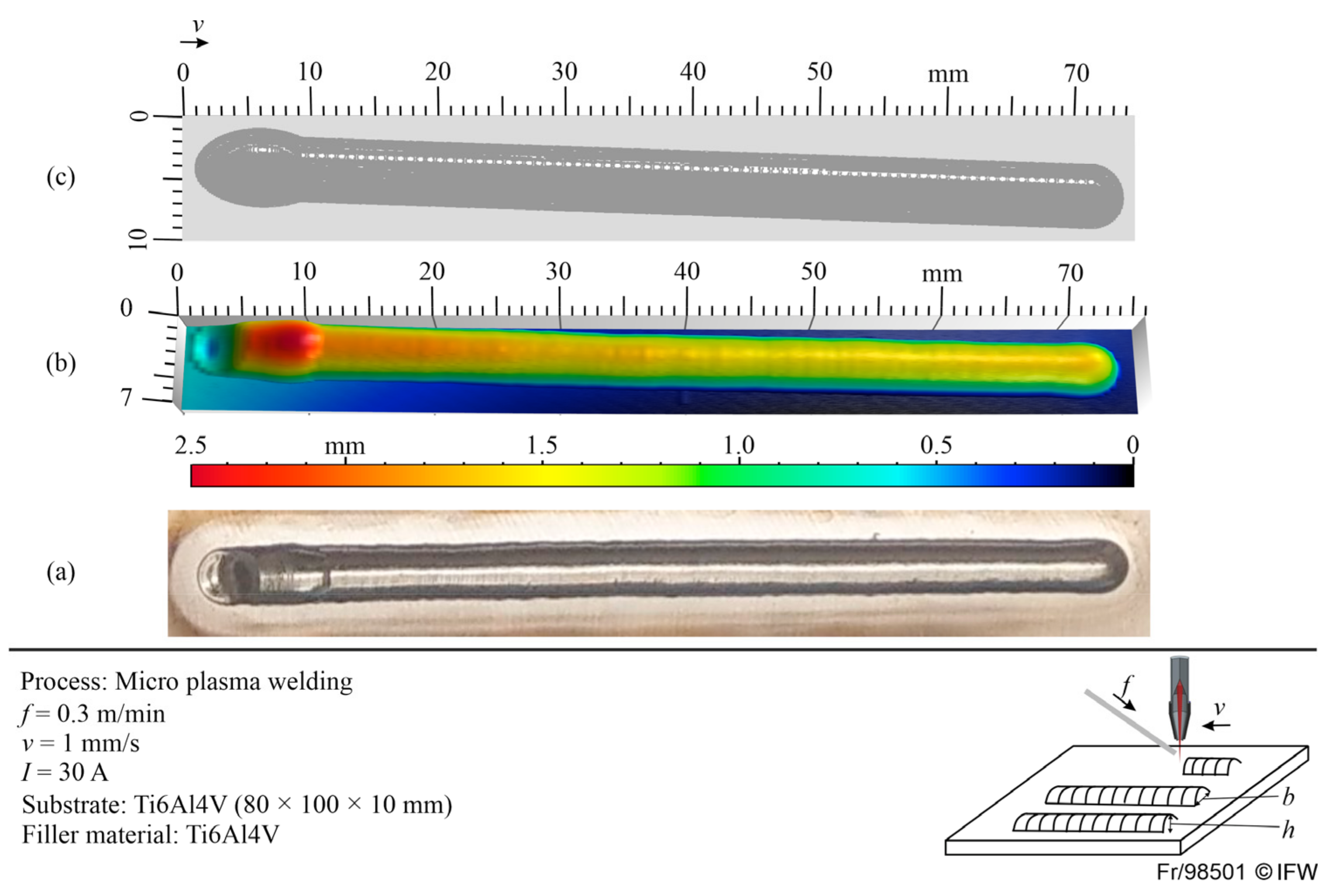
5. Application on Micro-Plasma Welding with Empirical Data

In this section, an application for the presented method is shown. In this example, a model for the prediction of the geometrical shape of a deposited material according to the process parameters is generated and experimentally validated.
An empirical model was generated based on conducted experiments by micro-plasma welding as the DED process for titanium alloy Ti6Al4V. The model predicted the width b and the height h of the shape of the deposited material depending on the given process parameters travel velocity v and current I . In the experiments, the material was deposited as a straight line with a length of 70 mm on a titanium substrate with a constant wire feed rate f of 0.3 m/min and using Argon as inert gas. To increase the statistical reliability, each experiment was repeated three times.
The height and the width of the deposited material were measured in the middle of lines by a tactile profile measuring device (MarSurf LD 130, Mahr GmbH, Göttingen, Germany), shown in Figure 6. The height of the deposited material increases by raising the applied current intensity. This is due to the higher energy input at a higher current. The higher energy input leads to a lower viscosity of the molten material and, thus, to a lower ratio between the height and the width of the deposited material. The changing of the height of the deposited material under variation of travel velocity can be also explained by Equation (3). Faster travel velocity leads to a decreasing volume of deposited material per unit length; this results in a smaller cross-section profile of the deposited material. Figure 7 shows this effect on the height of the deposited material.
Based on the experimental results, an empirical regression model was established by using the MATLAB Regression Learner Toolbox to predict the height and width of the deposited material. The quadratic regression functions to approximate the width or height as a function of the specified travel velocity and current are shown in Figure 8.
To simulate the shape of deposited material, the developed regression models were implemented in the simulation software IFW CutS [9]. According to the travel velocity in the process, the width and the height of the virtual tool are determined during the simulation. Thereby, the geometrical shape of the deposited material can be simulated.
In order to validate the simulation model, a simulation of additive manufacturing of a straight line of 70 mm length was conducted. The travel velocity changes in the inlet and outlet areas of the line due to the acceleration and deceleration of the welding torch, which leads to a change in the deposited material shape according to the developed model. This varying travel velocity during the manufacturing was considered in the used velocity within the simulation. Figure 9 shows a comparison between the simulated and measured deposited materials by micro-plasma welding.
Figure 8. Quadratic regression model for prediction of height and width of deposited material.
Jmmp 05 00009 g008
Figure 9. Comparison between the simulated and measured deposited materials (a) from the experiment; (b) measured by the tactile measuring system; (c) simulated in CutS.
Jmmp 05 00009 g009
As shown, the changing of the form of the deposited material in different zones with different relations between feed rate and travel velocity such as infeed and outfeed zones is simulated very closely to the experiment result. However, there is a notable non-match area between the simulation result and the experiment result, at the beginning of the deposited material (between 0 and 5 mm). The possible reason for this is that the exact behavior of the material under different temperatures was not considered in the model. Furthermore, the possible time delay between the start of welding and the movement of the welding torch was not considered. To include these effects, additional models to modify the virtual tool shape based on simulation or empirical data are needed.

6. Conclusions and Outlook

In this paper, an approach for a Dexel-based simulation of the deposited layer’s shape in DED processes was presented. In the simulation method, the geometrical shape of the deposited material can be adjusted by varying the virtual tool’s shape under consideration of multi-axis machine kinematics and local process conditions, which enables simulating different weld seam shapes or multi-layer deposition. Furthermore, an efficient process planning of additive manufacturing processes is possible. Another important advantage of the multi-Dexel-based additive process simulation is the ability to combine this method directly with the subsequent cutting process simulation. Using a coherent discretization model (multi-Dexel) for additive and subtractive process simulations enhances an integrated digital process chain for hybrid or combined manufacturing. This means that the machining simulation can be conducted using the discretized welding seam that was modeled with the additive process simulation. The repair process of turbine blades, for instance, is a typical application whereby the required cutting process of the deposited layers can subsequently be simulated.
The fluid dynamics of the melting zone and the influence of gravity and interactions between overlapping layers were not considered in this study. In future research, models for predicting the geometric shape of material deposition considering process parameters and tool path will be developed for specific processes and materials. Additionally, the changing of local temperature during the process will be investigated. The local temperature value can be calculated, for instance, by FEM simulations and stored in each Dexel. Based on this information, the virtual tool geometry can be adjusted according to the local temperature.

Author Contributions

Conceptualization, V.B., T.M. and S.F.; Methodology, V.B.; Software V.B., T.M. and S.F.; Validation, T.M. and S.F.; Investigation, V.B., T.M. and S.F.; Writing—Original Draft Preparation, V.B., T.M. and S.F.; Writing—Review & Editing, V.B., B.D., M.-A.D., T.M. and S.F.; Visualization, T.M. and S.F.; Supervision, V.B., B.D. and M.-A.D. All authors have read and agreed to the published version of the manuscript.

Funding

This research was funded by the Deutsche Forschungsgemeinschaft (DFG, German Research Foundation)—SFB 871/3—119193472 and under Germany’s Excellence Strategy within the Cluster of Excellence PhoenixD (EXC 2122, Project ID 390833453).

Data Availability Statement

The data presented in this study are available on request from the corresponding author.

Acknowledgments

The authors would like to thank subproject B6 of the SFB 871 for delivery of samples of deposited material and the software team of the IFW for their support regarding the implementation of the Dexel-based simulation method.

Conflicts of Interest

The authors declare no conflict of interest.

References

  1. Markl, M.; Körner, C. Multiscale Modeling of Powder Bed–Based Additive Manufacturing. Annu. Rev. Mater. Res. 2016, 46, 93–123. [Google Scholar] [CrossRef]
  2. Hejripour, F.; Binesh, F.; Hebel, M.; Aidun, D.K. Thermal modeling and characterization of wire arc additive manufactured duplex stainless steel. J. Mater. Process. Technol. 2019, 272, 58–71. [Google Scholar] [CrossRef]
  3. Li, R.; Xiong, J. Influence of interlayer dwell time on stress field of thin-walled components in WAAM via numerical simulation and experimental tests. Rapid Prototyp. J. 2019, 25, 1433–1441. [Google Scholar] [CrossRef]
  4. Hertel, M. Numerische Simulation des MSG-Prozesses. Ph.D. Thesis, Technische Universität Dresden, Dresden, Germany, 2016. [Google Scholar]
  5. Bai, X.; Colegrove, P.; Ding, J.; Zhou, X.; Diao, C.; Bridgeman, P.; Hönnige, J.R.; Zhang, H.; Williams, S. Numerical analysis of heat transfer and fluid flow in multilayer deposition of PAW-based wire and arc additive manufacturing. Int. J. Heat Mass Transf. 2018, 124, 504–516. [Google Scholar] [CrossRef] [Green Version]
  6. Seidel, C.M. Finite-Elemente-Simulation des Aufbauprozesses beim Laserstrahlschmelzen. Ph.D. Thesis, Technische Universität München, München, Germany, 2016. [Google Scholar]
  7. Van Hook, T. Real-Time Shaded NC Milling Display. SIGGRAPH Comput. Graph. 1986, 20, 15–20. [Google Scholar] [CrossRef]
  8. Requicha, A.; Rossignac, J. Solid modeling and beyond. IEEE Eng. Med. Boil. Mag. 1992, 12, 31–44. [Google Scholar] [CrossRef]
  9. Denkena, B.; Böß, V. Technological NC Simulation for Grinding and Cutting Processes Using CutS. In Proceedings of the 12th CIRP Conference on Modelling of Machining Operations, Donostia-San Sebastian, Spain, 7–8 May 2009; pp. 563–566. [Google Scholar]
  10. Aremu, A.; Brennan-Craddock, J.; Panesar, A.; Ashcroft, I.; Hague, R.; Wildman, R.D.; Tuck, C.J. A voxel-based method of constructing and skinning conformal and functionally graded lattice structures suitable for additive manufacturing. Addit. Manuf. 2017, 13, 1–13. [Google Scholar] [CrossRef]
  11. Böß, V.; Denkena, B.; Breidenstein, B.; Dittrich, M.-A.; Nguyen, H. Improving technological machining simulation by tailored workpiece models and kinematics. Procedia CIRP 2019, 82, 224–230. [Google Scholar] [CrossRef]
  12. Altintas, Y.; Kersting, P.; Biermann, D.; Budak, E.; Denkena, B.; Lazoglu, I. Virtual process systems for part machining opera-tions. CIRP Annals 2014, 63, 585–605. [Google Scholar] [CrossRef]
  13. He, S.; Zeng, X.; Yan, C.; Gong, H.; Lee, C.-H. Tri-Dexel Model Based Geometric Simulation of Multi-axis Additive Manufac-turing. IJIRA 2017, 10464, 819–830. [Google Scholar]
  14. Sun, Y.-J.; Yan, C.; Wu, S.-W.; Gong, H.; Lee, C.-H. Geometric simulation of 5-axis hybrid additive-subtractive manufacturing based on Tri-dexel model. Int. J. Adv. Manuf. Technol. 2018, 99, 2597–2610. [Google Scholar] [CrossRef]
  15. Dal, M.; Fabbro, R. An overview of the state of art in laser welding simulation. Opt. Laser Technol. 2016, 78, 2–14. [Google Scholar] [CrossRef] [Green Version]
  16. Wiederkehr, P.; Bergmann, J.A. An integrated macroscopic model for simulating SLM and milling processes. Prod. Eng. 2018, 12, 465–472. [Google Scholar] [CrossRef]
  17. Denkena, B.; Tracht, K.; Yu, J.-H. Advanced NC-Simulation based on the Dexelmodel and the HRMC-Algorithm. Prod. Eng. Res. Dev. 2006, 13, 91–94. [Google Scholar]
Figure 1. Dexel-based simulation of a milling process.
Jmmp 05 00009 g001
Figure 4. Dexel representation.
Jmmp 05 00009 g004
Figure 5. Material deposition in directed energy deposition (DED) processes.
Jmmp 05 00009 g005
Figure 6. Simulation of two different weld seam geometries with the developed method in IFW CutS. (a) Simulation of direction change of the tool path with square weld seam; (b) two-layer weld seam with geometry variation (infeed and outfeed).
Jmmp 05 00009 g006
Figure 7. Measured height and standard deviation for different travel velocity and currents.
Jmmp 05 00009 g007
Table 1. Overview of the latest studies about the geometric simulation of additive processes.
AuthorMethodProcess/ApplicationResults
He et al. (2017) [13]Calculation of material deposit with swept volume using a constant cross-section of deposited material for 5-axis Tri-Dexel-based simulationLaser metal deposition using an industrial robot/impeller, vane
  • Simulation of applied material deposit for different process parameter combinations
  • Better accuracy with new swept models
Aremu et al. (2017) [10]
  • Voxel-based method for generation of lattice structures via tesselation of a unit cell and trimming within the domain
  • Addition of a solid net-skin along the boundaries for better structural integrity of the trimmed struts and the lattice structure
Variable/objects with inner lattice structure
  • Suitable for different types of lattice structures and complex workpieces
  • Accuracy depends on voxel resolution
Dal et al. (2016) [15]
  • Finite volume-based simulation for modeling of physical interactions of the laser beam and material
  • Thermo-mechanical simulation of residual stresses and distortions
  • Multi-physical simulation of heat transfer/fluid flow
  • Electromagnetic simulation of laser–material interactions including reflections of the laser beam
  • Modeling of phase transformation and liquid/gas interface
Laser welding/various applications
  • Research is constrained by the knowledge regarding heat transfer
  • For multi-physical simulations, thermophysical properties at high temperature are lacking
  • The gas behavior inside the keyhole must be considered
Hertel (2016) [4]
  • FE-based simulation including modeling of electric arc, droplet formation and velocity distribution inside of the weld pool
  • Simulation of the wire and droplet shape
Gas metal arc welding (GMAW)
  • Description of the GMAW process with high spatial and temporal resolution
  • Prediction of processes during formation of welding seam
Seidel (2016) [6]
  • FE-based simulation for modeling of build-up process
  • Prediction of part distortions based on modeling of transient temperature field
  • Reduction in part distortions by optimized process planning
Laser welding/boroscop eye and turbine blade (Inconel 718)
  • Improvement of dimensional accuracy by 41%
  • Transfer of the method to other materials, e.g., steels, aluminum and titanium alloys
  • Reduction in computational time
Wiederkehr and Bergmann (2018) [16]
  • Macroscopic model for geometric simulation using Poisson disk sampling for the distribution of powder particles
  • Usage of an empirical model which is parametrized by digitized and measured reference structures
Selective laser melting (SLM) and milling process/impeller and other applicationsSimulated geometry can be used in subsequent milling simulations
Sun et al. (2018) [14]
  • Tri-Dexel based representation of additive swept volume and conversion into triangular models for visualization
  • Usage of workpiece after the additive manufacturing as a workblank for sub-tractive manufacturing simulation
Hybrid additive–subtractive manufacturing (SLM and 5-axis-milling)/impellerImprovement of micro swept volume model
Publisher’s Note: MDPI stays neutral with regard to jurisdictional claims in published maps and institutional affiliations.

