Article

An Efficient Ultraprecision Machining System Automating Setting Operations of Roughly Machined Workpiece

1
Department of Mechanical Systems Engineering, Tokyo University of Agriculture and Technology, 2-24-16, Naka-cho, Koganei-shi, Tokyo 184-8588, Japan
2
Department of Mechanical Engineering, Chubu University, 1200 Matsumoto-cho, Kasugai-shi, Aichi 487-8501, Japan
*
Author to whom correspondence should be addressed.
J. Manuf. Mater. Process. 2021, 5(1), 11; https://doi.org/10.3390/jmmp5010011
Submission received: 30 November 2020 / Revised: 24 December 2020 / Accepted: 16 January 2021 / Published: 19 January 2021
(This article belongs to the Special Issue Progress in Precision Machining)

Abstract

:
Ultraprecision machining is required in many advanced fields. To create precise parts for realizing their high performance, the whole machining process is usually conducted on the same ultraprecision machine tool to avoid setting errors by reducing setting operations. However, feed rate is relatively slow and machining efficiency is not so high compared to ordinary machine tools. Thus, the study aims to develop an efficient ultraprecision machining system including an industrial robot to avoid manual setting and to automate the setting operations. In this system, ultraprecision machining is conducted for the workpiece having a shape near the target shape, which is beforehand prepared by ordinary machine tools and is located on the machine table by means of an industrial robot. Since the setting errors of the roughly machined workpiece deteriorate machining accuracy, the differences from the ideal position and attitude are detected with a contact type of on-machine measurement device. Numerical control (NC) data is finally modified to compensate the identified workpiece setting errors to machine the target shape on an ultraprecision machine tool. From the experimental results, it is confirmed that the proposed system has the possibility to reduce time required in ultraprecision machining to create precise parts with high efficiency.

1. Introduction

Recent years, a functional surface with microstructure has been applied in many advanced fields such as optics, electronics, information technology, and biomedicine [1,2]. In order to realize their high performance of these surface functions, the requirement of fabrication becomes stricter with the surface roughness and form-accuracy in nanometer-order [3,4]. Therefore, ultraprecision machining is a very promising method currently because of its advantages such as high flexibility, low cost, and low environmental burden. Many researchers have made important contributions to ultraprecision machining by means of ultraprecision machine tools to create the precise parts. For example, Yan et al. machined micropyramid arrays on NiP molds with sharpened single-crystalline diamond tools and the depth range of the elements reaches the micron level and the machined microstructure is precisely transcribed to glass surfaces [5]. Additionally, Kakinuma et al. machined 3D microfluidic chip with sub-micron- to millimeter-scale channels by cryogenic milling on Polydimethylsiloxane [6]. Furthermore, Dutterer et al. investigated the suitable parameters for freeform milling of germanium and fabricated alvarez lens with the roughness of 9 nm Ra [7]. The authors also have developed a computer-aided manufacturing (CAM) system for creating a microinducer by five-axis control ultraprecision machining [8].
Although ultraprecision machine tools have been developed to realize high positional accuracy and resolution, it is very difficult to create parts with the nanometric accuracy due to many slight errors such as machine tool configuration, tool contour, and setting operation. Therefore, these errors must be clearly detected and completely compensated. Based on the multi-body system theory, Liu et al. [9] established a machining error model for a three-axis ultraprecision lathe to study the influence of geometric errors of machine tool configuration. Sun et al. also developed a thermodynamics-based structure optimization method to decrease the thermal displacements during machining process [10]. Additionally, Nagayama and Yan used a white light interferometer to measure the tool contour error and compensated it in generated tool paths [11]. Furthermore, Maeng and Min proposed a method to identify the position independent geometric errors and tool setting by on-machine measurement system for a multi-axis controlled ultraprecision machine tool [12].
The authors have also focused on the tool setting, which is one of the critical factors of the machining accuracy, and developed methods to detect the setting errors by conducting a test cutting on a dummy work and using a non-contact measurement device [13,14]. On the other hand, work setting errors have been ignored because the whole machining process consisting of rough cutting and finish cutting is usually conducted on the same ultraprecision machine tool, to reduce the tool and work setting operations on an ultraprecision machine tool. However, feed rate is relatively slow and machining efficiency is not so high compared to the ordinary machine tools. As the target shape is complex and the machining area becomes wide, machining time and cost increase rapidly. In order to reduce the machined volume on an ultraprecision machine tool, rough cutting is conducted by an ordinary machine tool to obtain the workpiece having near targeted shape. For example, fabrication of an optical part, where texture patterns are added on a freeform surface, would cost a lot of time if both freeform surface machining and texture patterns creation are conducted on the same ultraprecision machine tool. However, when the freeform surface is roughly machined in advance, the total machining time would be reduced because only finish cutting and texture patterns creation are conducted on the ultraprecision machine tool. Thus, the study aims to develop an efficient ultraprecision machining system including an industrial robot to avoid manual setting and to automate the setting operations.
In the proposed system, ultraprecision machining is conducted for the workpiece having a shape near the target shape, which is prepared beforehand by ordinary machine tools to reduce the machined volume of ultraprecision machining and to improve the machining efficiency. This workpiece is located on the machine table by means of an industrial robot. Therefore, the industrial robot is an essential element of this system, which connects rough cutting by an ordinary machine tool and finish cutting by an ultraprecision machine tool. Although the industrial robot removes the manual setting, the setting errors of the roughly machined workpiece are left due to the low repeatability and inevitably deteriorate machining accuracy. In order to identify the setting errors caused by the differences from the ideal position and attitude, actual position and attitude are detected with a contact type of on-machine measurement device. NC data is finally modified to compensate the identified workpiece setting errors to machine the target shape on an ultraprecision machine tool. From the experimental results, it is confirmed that the proposed system has the possibility to reduce time required in ultraprecision machining to create precise parts with high efficiency.

2. Workpiece Setting Errors and Their Compensation

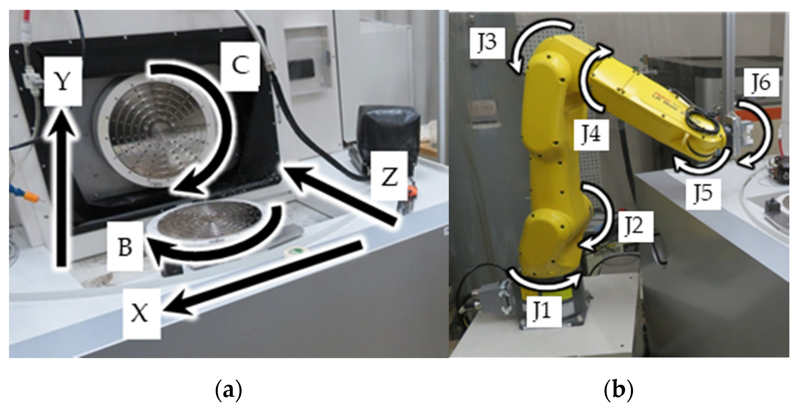
2.1. Experimental Device

Figure 1 illustrates a five-axis controlled ultraprecision machining center ROBOnano α-0iB (FANUC corp.) and an industrial robot LR Mate 200iD (FANUC corp.) used in the study. The ultraprecision machining center is comprised of three translational axes (X, Y and Z) and two rotational axes (B and C). The positioning resolution of each translational axis was 1 nm and of each rotational axis was 0.00001°. All the axes were equipped with aero-static bearings to achieve friction-free movements. The workpiece was beforehand machined by an ordinary three-axis controlled machining center, which had a 1 μm resolution of each translational axis and then was set on a vacuum chuck that was mounted on a C axis table of the ultraprecision machine tool by the robot, which was a six-axis vertical articulated robot. The repeatability of the robot is 30 μm and the maximum allowable payload is 7 kg in the catalog. Although the repeatability is not so high, in terms of automation of workpiece mounting, an industrial robot is suitable for the automation of workpiece setting in case the setting errors are adequately compensated. A non-rotational diamond tool was mounted on a B axis table via an angle plate.
In order to detect the actual workpiece position and attitude, a contact type on-machine measurement device NANOCHECKER (FANUC corp.) was mounted on the B axis table of the ultraprecision machining center beside the angle plate, as shown in Figure 2. A probe on the device was pushed by adjustable compressed air to decrease the elastic deformation caused by contact forces. The device was controlled by the same NC system of ultraprecision machine tool. When the ruby ball, whose radius is 0.25 mm, on the probe tip follows the workpiece surface, the displacement of the probe was recorded with 1 nm resolution. The surface profile and position were calculated by the measured probe displacement together with the machine coordinates.
The proposed system can be applied to all the geometrical features that are created by general ultraprecision machining, in theory. However, due to the limitation of robot handling and the specification of vacuum chuck, for example, some features on an extremely tiny or large workpiece are inadequate for the presented technique. Additionally, since the system adopts the self-made vacuum chuck, the range of the cutting conditions were set to be conservative compared to general ultraprecision machining. If a high-performance vacuum chuck is used, the cutting conditions become much closer to general conditions.

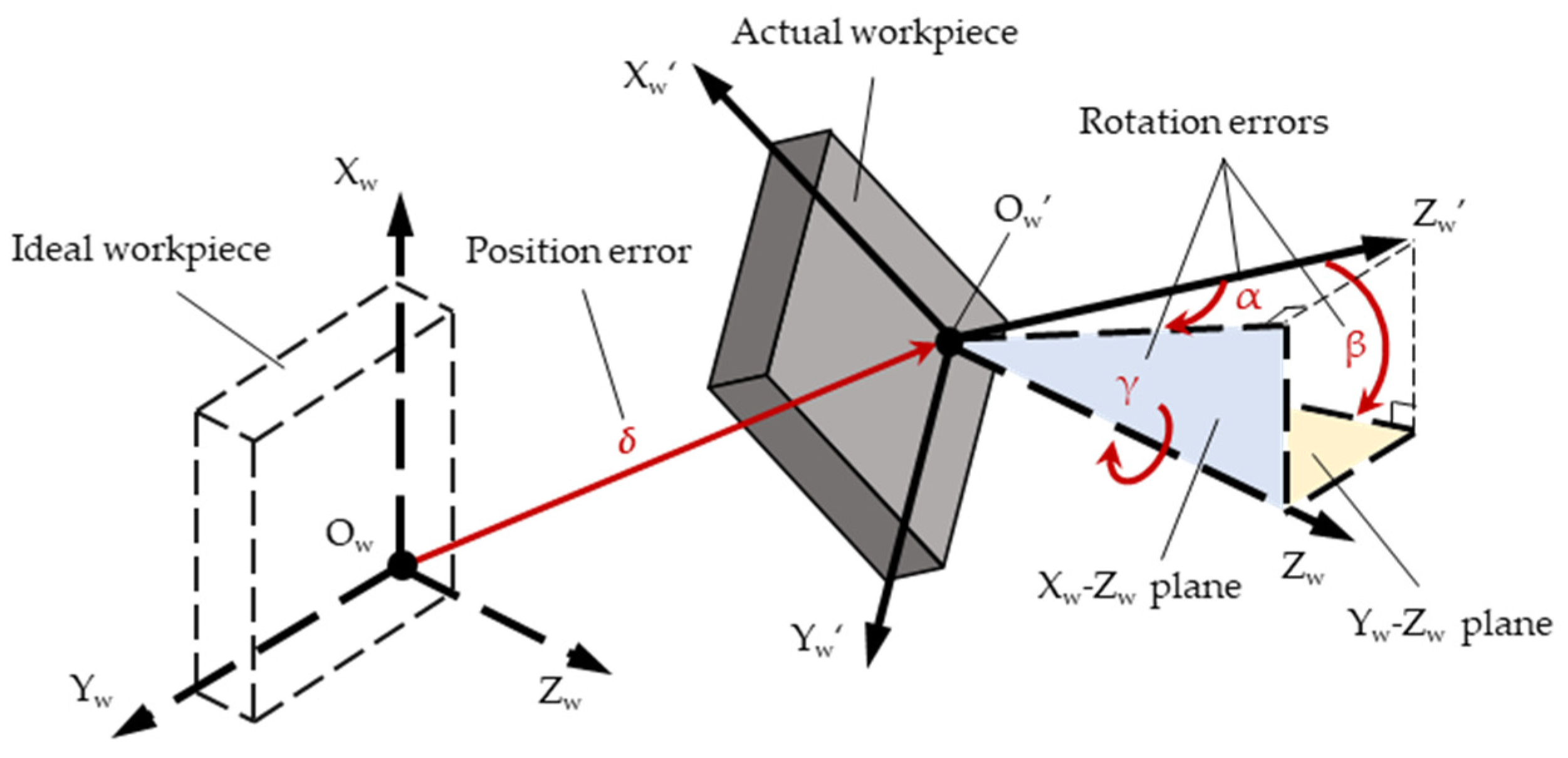
2.2. Workpiece Coordinate System and Workpiece Setting Errors

The workpiece coordinate system is used to generate an NC program and is usually established based on the actual position of the located workpiece. For example, it is assumed that the position of one corner of a correct cuboid is defined as the origin and three crossing vertical edges agree with the axes of the workpiece coordinate system. Some precise jigs may be used to locate the workpiece at the known position, where the workpiece coordinate system is generally parallel to the machine coordinate system, on machine tool tables accurately and the workpiece is machined by a prepared NC program. However, it cannot avoid the dependence on manual setting in this way. On the other hand, although an industrial robot can set the workpiece automatically by using a vacuum chuck and so on, the relative low repeatability, in comparison to the resolution of the ultraprecision machine tool, makes the workpiece offset so that it cannot meet the needs of ultraprecision machining. If the NC program was generated based on the ideal workpiece coordinate system established by the assumed position and attitude, the setting errors would make an overcut or aircut and lead to the deterioration of machining accuracy. Thus, an on-machine measurement device was used in this study to detect the ideal workpiece position and attitude in order to identify workpiece setting errors. The workpiece setting errors are described in Figure 3. The workpiece coordinate systems were established based on each workpiece position and attitude of the ideal and actual situations, respectively. It was found that the workpiece setting errors consisted of position error δ and rotation errors α, β, and γ. Position error δ was the offset of the system origin from its ideal situation. Rotation errors α, β and γ were the rotational angles of workpiece compared to the ideal situation around Xw, Yw, and Zw axis of the ideal workpiece coordinate system, respectively.

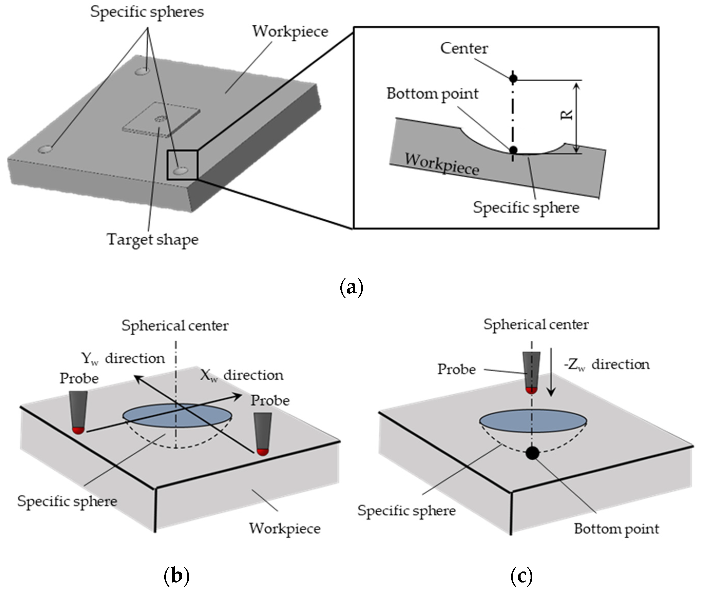
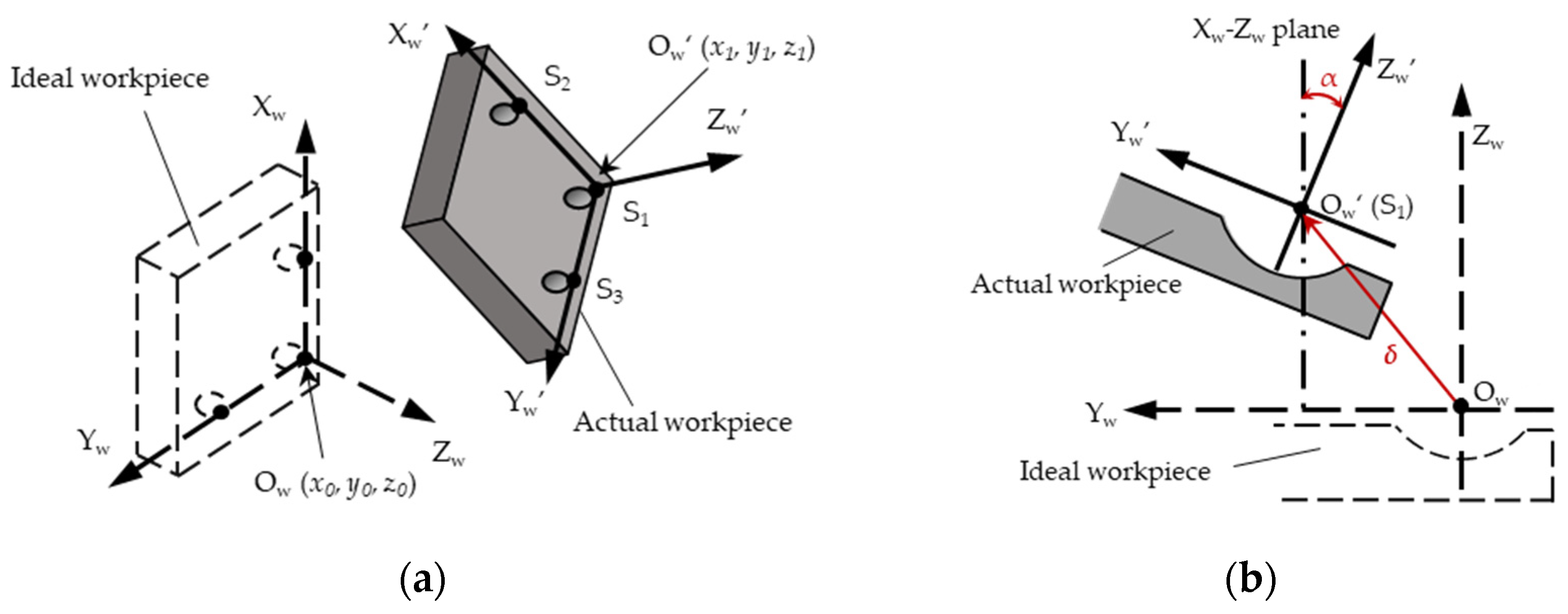
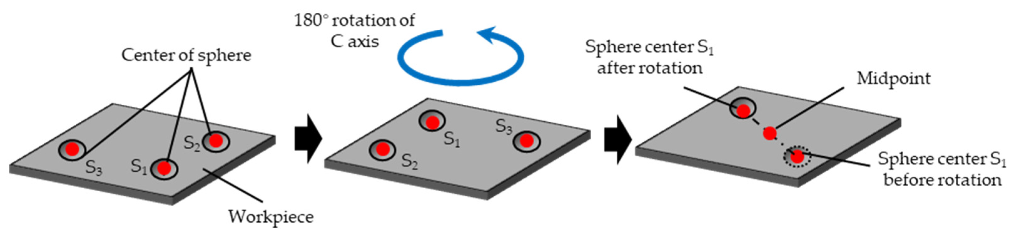
2.3. Identification of Workpiece Setting Errors

To detect the actual position and attitude of workpiece on ultraprecision machine tool, a reference of workpiece is necessary for the usage of an on-machine measurement device. From this point of view, the center position of a sphere is suitable for the reference because of the symmetrical characteristic. Therefore, in this study, three specific spheres, as shown in Figure 4a, were used to detect the actual workpiece position and attitude. They were created by rough cutting using a ball-end mill at the known locations. The measured sphere radius was much larger than the probe radius of the used on-machine measurement device. The probe was set to be parallel to Zw axis of the ideal workpiece coordinate system to detect the displacement along Zw axis. The sphere surface was scanned in two different directions orthogonal to each other, as shown in Figure 4b, and its center position was estimated by the least squares method. Though Xw and Yw coordinates of the sphere center can be accurately estimated, Zw coordinate may have some errors because the machined sphere radius is a little different from the targeted one. Therefore, in order to obtain the accurate coordinate of sphere center, the probe was fed in the –Zw direction of the ideal workpiece coordinate system, until the probe touched the spherical surface, as shown in Figure 4c. This position was the bottom point of specific sphere, the sphere center was over the bottom point along Zw axis, and the distance was the sphere radius which was the average radius of three different spheres. This sphere center position was used as the reference. However, the machining errors of the sphere would influence the estimation of sphere center coordinates to shift the real center position, thus forming an error. From the simple calculation, the shift of estimated sphere center coordinates will influence 5 μm against the workpiece position and 0.02 degree against the workpiece inclination, respectively. On the other hand, the form error is not usually so large and the influence on the workpiece position is expected to be less than 1–2 μm. This was in accordance with the errors obtained in the machining tests. Since the arrangement of spheres was already known, the actual position and attitude of the roughly machined workpiece on the ultraprecision machine tool can be detected based on the coordinates of those reference points on the ideal workpiece coordinate system.
Figure 5 illustrates an example to identify the workpiece setting errors. In Figure 5a, S1, S2, and S3 were the references of the center points of three specific spheres and their positions were detected with the on-machine measurement device. Vectors S1S2 and S1S3 agreed with Xw’ and Yw’ axes of the actual workpiece coordinate system, respectively. In addition, the cross product of Xw’ and Yw’ was defined as Zw’ axis that corresponds to Zw axis of the ideal workpiece coordinate system. ex, ey and ez are the unit vectors of each axis of the actual workpiece coordinate system, respectively. As shown in Figure 5b, rotation error α is the angle from Zw’ axis to Xw-Yw plane. When ez is expressed as (ezx, ezy, ezz) in the ideal workpiece coordinate system, the rotation error α can be calculated by the following equation:
α = arctan ( e z z / e z x ) .
Similarly, rotation error β is the angle from Zw’ axis to Yw-Zw plane. Thus, the rotation error β can be expressed by Equation (2):
β = arctan ( e z z / e z y ) .
Rotation error γ is the angle of Xw’ and Xw axes after Xw’ axis was rotated around Xw axis by α degrees and around Yw axis by β degrees, to make Xw’ axis located on Xw-Yw plane. Therefore, the rotation error γ can be obtained by the following equation:
γ = arccos [ R x ( α ) R y ( β ) e x · e x 0 ] .
In the above equations, Rx and Ry are the rotation matrixes around Xw and Yw axes of the ideal workpiece coordinate system, respectively. ex0 is the unit vector of Xw axis of the ideal workpiece coordinate system.
When the ideal origin was expressed as (x0, y0, z0) and the point S1 was expressed as (x1, y1, z1), the position error δ shown in Figure 3 can be obtained:
δ = ( x 1 x 0 ,   y 1 y 0 , z 1 z 0 ) .

2.4. Compensation of Workpiece Setting Errors

In the case of multi-axis control machining, the attitude and position of the workpiece are always changed according to the orientation of the C axis table where the workpiece is mounted. Thus, the distance from the rotational center of C axis should be estimated before setting errors compensation. After the center point of a specific sphere was detected with the on-machine measurement device, C axis was rotated by 180 degrees and the bottom point was detected again. As shown in Figure 6, the midpoint of the bottom points that were before and after the rotation becomes the rotational center of C axis. In practice, the estimation was conducted based on the three different specific spheres and the average was taken to obtain the position of C axis rotational center.
According to the estimated rotation errors and position error, workpiece setting errors can be compensated by modifying the original NC program (x, y, z, b, c) to (X, Y, Z, B, C) as follows:
B = b + β ,
C = c + γ ,
( X , Y , Z ) = [ ( x , y , z ) × R z ( C ) R x ( α ) R y ( β ) ( X c , Y c , 0 ) δ ] R z ( C ) + ( X c , Y c , 0 ) + δ .
In the above equations, Rx, Ry, and Rz are the rotation matrixes against Xw, Yw, and Zw axis of the ideal workpiece coordinate system, respectively. (Xc, Yc) is the coordinate of the rotational center of the C axis table in the ideal workpiece coordinate system. B axis was rotated by β degrees to make the tool attitude meet the actual workpiece. The rotation error γ was cancelled by changing the rotation angle of the C axis table, and the other errors were compensated by modifying the tool paths to agree with them in the actual workpiece coordinate system.

3. Machining Experiments and Results

In order to confirm the effectiveness of the workpiece setting errors compensation method mentioned above, two experiments were conducted by using a non-rotation diamond tool. The first one was an experiment to create some simple straight grooves and the other one was an experiment to conduct finish cutting on a roughly machined workpiece.

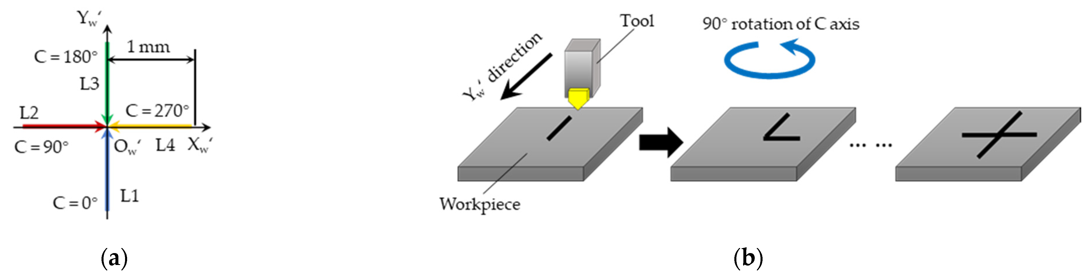
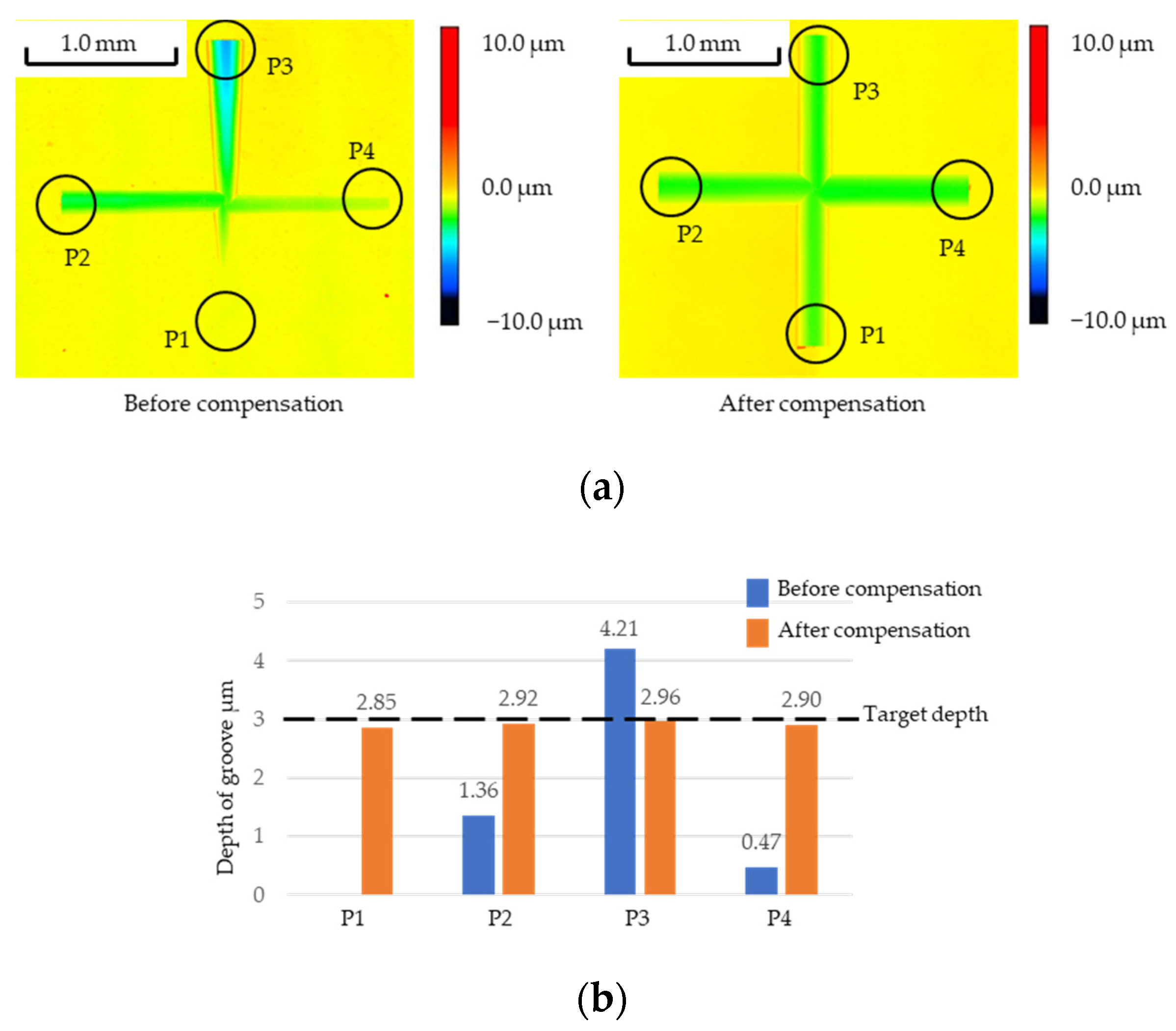
3.1. Creation of Micro Grooves

As shown in Figure 7a, the target shape consisted of four linear crossing grooves with 3 μm depth and 1 mm length. A beforehand machined workpiece, that had three specific spheres on the workpiece surface, was mounted on the C axis table by a robot and was cut by a diamond tool. This machining experiment was conducted twice before and after compensation of workpiece setting errors, respectively. Each groove was created by feeding the diamond tool along Yw’ direction of the actual workpiece coordinate system, whereby the C axis table was rotated by 90 degrees. The cutting conditions are summarized in Table 1. In the experiment, the depth of each microgroove was measured. When the workpiece setting errors were not compensated successfully, the tool would cut with incorrect depth and the grooved depth would change continuously along the groove. The depth change was related to the workpiece inclination. In the case that the actual workpiece surface had an inclination against the ideal workpiece coordinate system, the groove depth was deeper at the area where the estimated workpiece surface was above the ideal surface. Similarly, the groove depth was smaller at the area where the estimated workpiece surface was below the ideal surface.
The machined results, which were measured with a laser microscope (VK-X50 KEYENCE) before and after compensating the rotation errors and position errors of the workpiece, are shown in Figure 8a. It was found that the machined result before compensation was quite different from the targeted shapes. Due to the influence of workpiece setting errors, the depth of each groove was quite different and even the groove did not appear completely when C axis was 0 degrees. However, after workpiece setting errors were compensated for, all the grooves were created according to the targeted shape. The groove depth at the end of each groove was measured with laser microscope three times. The average values are summarized in Figure 8b. It was found that the difference of cutting depths decreases within about one hundred nanometers and workpiece setting errors are compensated by the proposed method that detects the actual workpiece position and attitude by on-machine measurement.

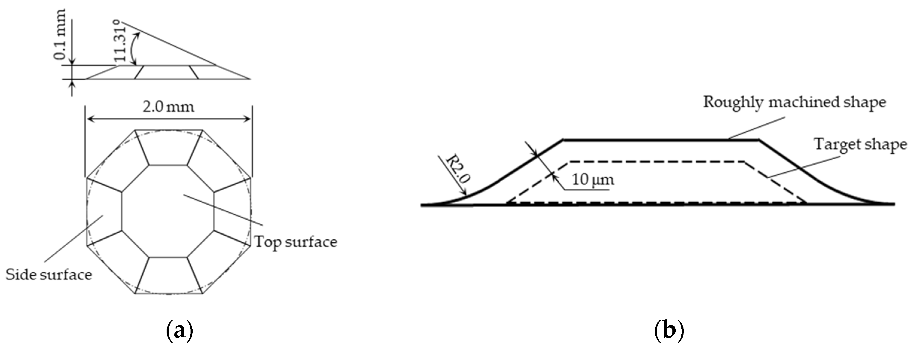
3.2. Machining a Diamond Crown

The experiment mentioned above shows the feasibility of the proposed compensation method of workpiece setting errors. However, the availability of ultraprecision machining on a roughly machined workpiece still needed to be verified. This is because the diamond crown contains one top surface and eight side surfaces with slope, and each side surface must be cut with different heights and at different C axis coordinates. Therefore, this shape can show the effectiveness against complex shapes created by multi-axis control machining based on the measurement of edge distance and inclination of each side surface. An experiment to create a diamond crown, shown in Figure 9a, was conducted. The target shape was located at the middle of the workpiece of an aluminum alloy. It had nine surfaces and the slope of the side surface was 11.31 degrees, to be measured by laser microscope accurately.

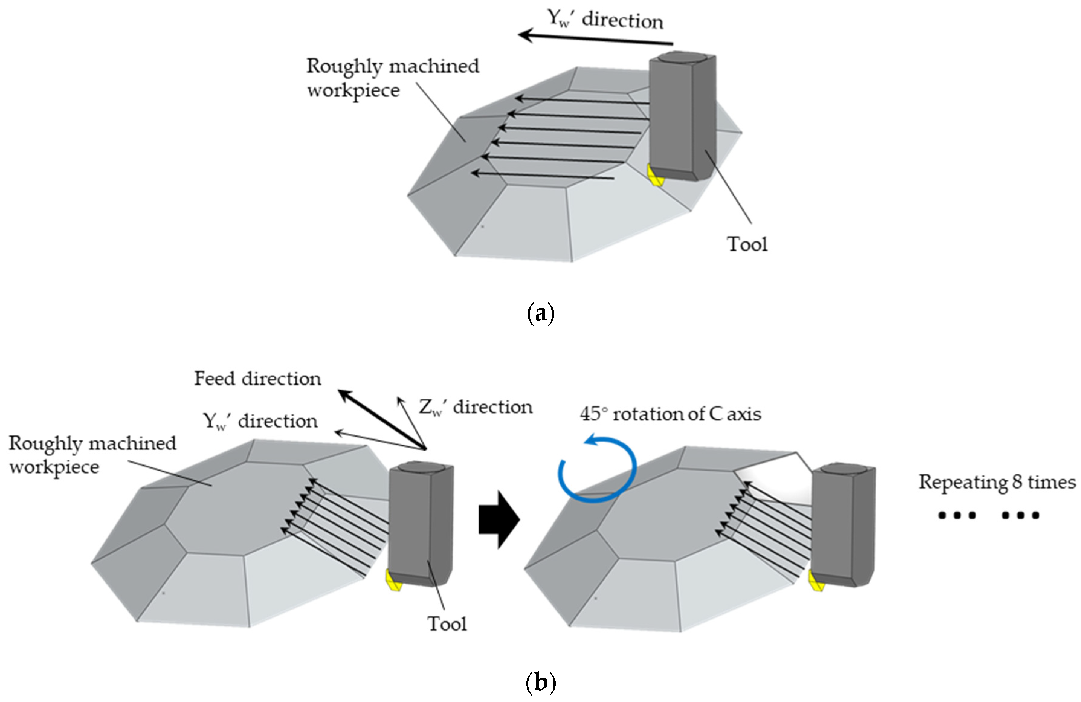
3.2.1. Rough Cutting

In order to shorten the machining time, the workpiece was set on an ordinary machine tool to obtain the approximated target shape by using a ball-end mill with R2.0. To make sure that the machining result contains the target shape safely, the workpiece shape after rough cutting was designed 10 μm larger than the targeted size, as shown in Figure 9b. Finally, three specific spheres were machined by the same ball endmill to ensure that the specific spheres and roughly machined shape agreed with the same coordinate system.

3.2.2. Ultraprecision Machining of the Workpiece

The roughly machined workpiece was mounted on the C axis table of the ultraprecision machine tool and was cut by a non-rotational diamond tool with R2.0 nose. The actual workpiece position was detected by scanning the three specific spheres. The top surface of the crown was machined by tool paths along Yw’ direction, as shown in Figure 10a, and the side surfaces were machined by using Yw’ and Zw’ axes at the same time to make the tool paths, shown in Figure 10b, parallel to the side surfaces where the C axis table was rotated by 45 degrees. The cutting conditions are summarized in Table 2. In the experiment, ultraprecision machining for finishing was conducted in the conditions before and after the workpiece setting errors were rightly compensated.

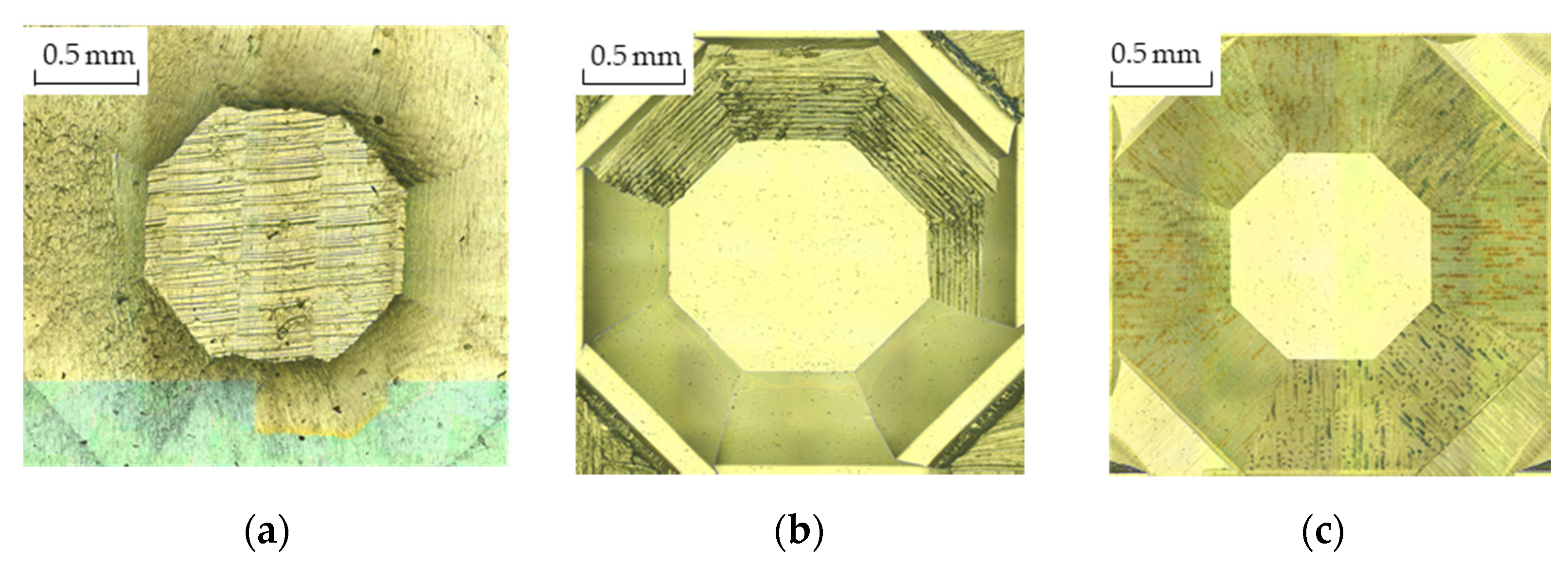
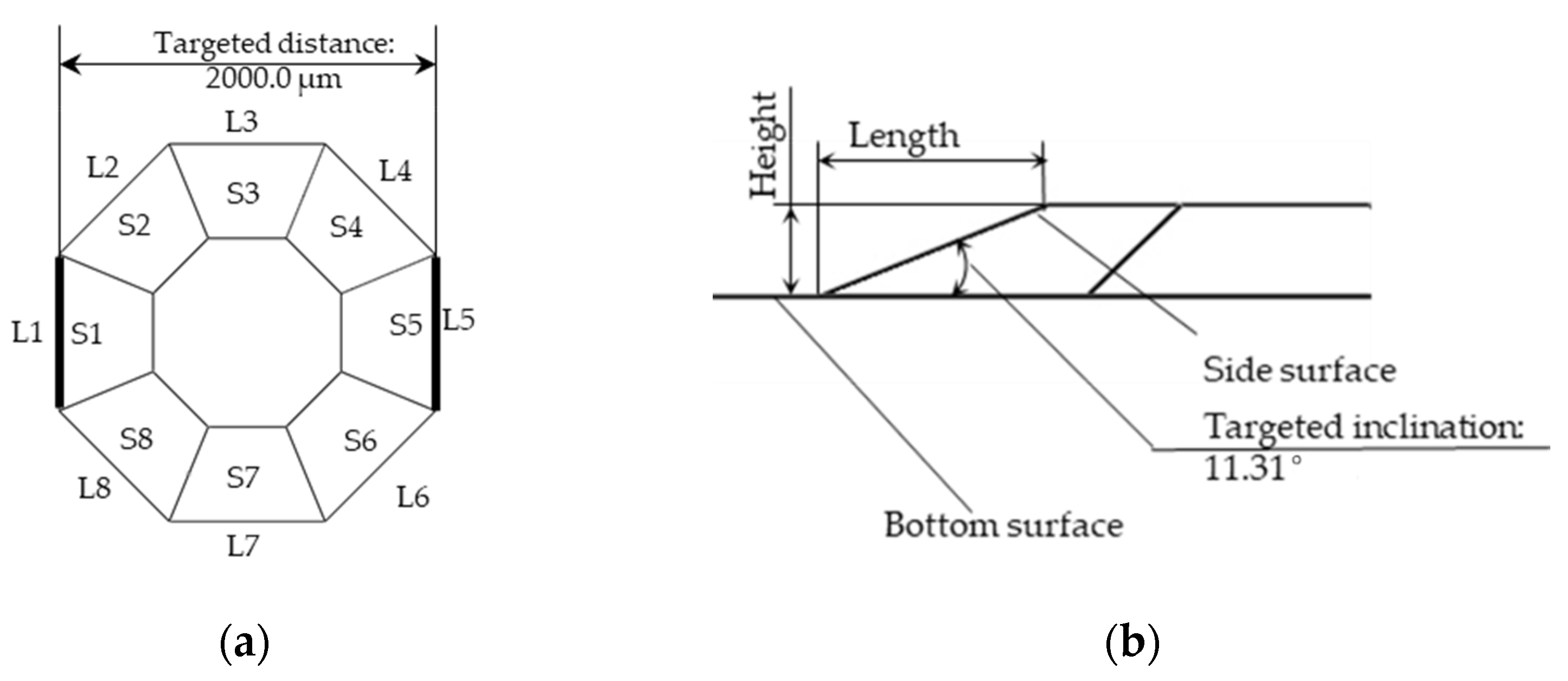
3.2.3. Machining Results and Analysis

Figure 11 shows observed microscopic images of the machined shapes that were before ultraprecision machining, before compensation, and after compensation, respectively. It was found that the machined shape before compensation was quite different from the target one and some surfaces were not created correctly. However, the result after compensation was almost the same as the target shape.
The machined shapes before and after compensation were also measured with laser microscope. The distances of two opposite edges which were parallel to each other, shown in Figure 12a, were measured by making one line consisting of two points on an edge and another parallel line located on the other edge. It was related to the agreement between the C table center and the workpiece center influenced by setting errors. When the C table center did not agree with the workpiece center, the edge distance became longer. The measurement was repeated three times to take the average value. The angle between side surface and bottom surface, shown in Figure 12b, was also calculated based on measuring the height and length of the side surface. For multi-axis control machining, the disagreement between the C table center and the workpiece center would also result in the angle between the side surface and the bottom surface differing from the target value. If the angle of one side surface and the bottom surface became larger than the target value, the angle of the opposite side surface and bottom surface would become smaller. The results of distances between four different couples of edges and inclinations of eight side surfaces are summarized in Table 3. It was found that the modified NC program based on the identified workpiece setting errors enables obtainment of almost the same machined shape as the target one. From the result of this experiment, it was confirmed that the proposed method is effective for conducting the ultraprecision machining on a roughly machined workpiece by the proposed workpiece setting errors compensation method.

3.2.4. Machining Time

The total machining time of the diamond crown was estimated to be about 9.5 h, including 12 min of workpiece setting by a simulation software Ncsimulator V3.00 (FANUC Corp., Oshino-mura, Japan). When the targeted shape was created from the cuboid original workpiece with the same cutting conditions and tool paths as the finish cutting of the proposed method, the total machining time would be more than 40 h. Therefore, about 76% of machining time was saved.

4. Conclusions

In this study, an ultraprecision machining system including an industrial robot to avoid manual setting and to automate the setting operations is devised.
  • A workpiece is located by an industrial robot and the actual position and attitude of the workpiece on an ultraprecision machine tool is detected by detecting the references that are beforehand machined on the workpiece with an on-machine measurement device.
  • Workpiece setting errors are compensated by modifying an NC program based on the ideal workpiece coordinate system to make tool paths agree with the actual workpiece position.
  • From the cutting experiments, it is found that the proposed method would be effective to save machining time by finishing against a roughly machined workpiece.

Author Contributions

Conceptualization, K.N. and Y.T.; methodology, M.X.; investigation, M.X.; resources, M.X.; data curation, M.X.; writing—original draft preparation, M.X.; writing—review and editing, K.N.; visualization, M.X.; supervision, K.N.; project administration, K.N.; funding acquisition, K.N. All authors have read and agreed to the published version of the manuscript.

Funding

This study was financially supported by Grant-in Aid for Scientific Research (No. 16KK0144 and 18H01347) of the Japan Society for the Promotion of Science (JSPS).

Institutional Review Board Statement

Not applicable.

Informed Consent Statement

Not applicable.

Acknowledgments

The authors express special thanks to the efforts of former students who conducted numerous experiments.

Conflicts of Interest

The authors declare no conflict of interest.

References

  1. Brinksmeier, E.; Gläbe, R.; Schönemann, L. Review on diamond-machining processes for the generation of functional surface structures. CIRP J. Manuf. Sci. Technol. 2012, 5, 1–7. [Google Scholar] [CrossRef]
  2. Zhang, S.; Zhou, Y.; Zhang, H.; Xiong, Z.; To, S. Advances in ultra-precision machining of micro-structured functional surfaces and their typical applications. Int. J. Mach. Tools Manuf. 2019, 142, 16–41. [Google Scholar] [CrossRef]
  3. Fang, F.Z.; Zhang, X.D.; Weckenmann, A.; Zhang, G.X.; Evans, C. Manufacturing and measurement of freeform optics. CIRP Ann. Manuf. Technol. 2013, 62, 823–846. [Google Scholar] [CrossRef]
  4. Fang, F.Z.; Zhang, X.D.; Gao, W.; Guo, Y.B.; Byrne, G.; Hansen, H.N. Nanomanufacturing—Perspective and applications. CIRP Ann. Manuf. Technol. 2018, 67, 683–705. [Google Scholar]
  5. Yan, J.; Oowada, T.; Zhou, T.; Kuriyagawa, T. Precision machining of microstructures on electroless-plated NiP surface for molding glass components. J. Mater. Process. Technol. 2009, 209, 4802–4808. [Google Scholar] [CrossRef]
  6. Kakinuma, Y.; Kidani, S.; Aoyama, T. Ultra-precision cryogenic machining of viscoelastic polymers. CIRP Ann. Manuf. Technol. 2012, 135, 1–11. [Google Scholar] [CrossRef]
  7. Dutterer, B.; Lineberger, J.L.; Smilie, P.J.; Hildebrand, D.S.; Harriman, T.A.; Davies, M.A.; Suleski, T.J.; Lucca, D.A. Diamond milling of an Alvarez lens in germanium. Precis. Eng. 2014, 38, 398–408. [Google Scholar] [CrossRef]
  8. Nakamoto, K.; Ishida, T.; Kitamura, N.; Takeuchi, Y. Fabrication of microinducer by 5-axis control ultraprecision micromilling. CIRP Ann. Manuf. Technol. 2011, 60, 407–410. [Google Scholar] [CrossRef]
  9. Liu, X.; Zhang, X.; Fang, F.; Liu, S. Identification and compensation of main machining errors on surface form accuracy in ultra-precision diamond turning. Int. J. Mach. Tools Manuf. 2016, 105, 45–57. [Google Scholar] [CrossRef]
  10. Sun, L.; Ren, M.; Hong, H.; Yin, Y. Thermal error reduction based on thermodynamics structure optimization method for an ultra-precision machine tool. Int. J. Adv. Manuf. Technol. 2017, 88, 1267–1277. [Google Scholar] [CrossRef]
  11. Nagayama, K.; Yan, J. Measurement and Compensation of Tool Contour Error Using White Light Interferometry for Ultra-Precision Diamond Turning of Freeform Surfaces. Int. J. Autom. Technol. 2020, 14, 654–664. [Google Scholar] [CrossRef]
  12. Maeng, S.; Min, S. Simultaneous geometric error identification of rotary axis and tool setting in an ultra-precision 5-axis machine tool using on-machine measurement. Precis. Eng. 2020, 63, 94–104. [Google Scholar] [CrossRef]
  13. Baba, S.; Nakamoto, K.; Takeuchi, Y. Multi-axis control ultraprecision machining based on tool setting errors compensation. Int. J. Autom. Technol. 2016, 10, 114–120. [Google Scholar] [CrossRef]
  14. Xu, M.; Nakamoto, K.; Takeuchi, Y. A Compensation Method of Tool Setting Errors Based on Non-Contact On-machine Measurement. Int. J. Autom. Technol. 2020, 64, 66–72. [Google Scholar] [CrossRef]
Figure 1. Experimental setup used in this study: (a) Five-axis controlled ultraprecision machining center ROBOnano α-0iB (FANUC corp.). (b) Six-axis vertical articulated industrial robot LR Mate 200iD (FANUC corp.).
Jmmp 05 00011 g001
Figure 2. A non-rotational diamond tool is mounted on a B axis table via an angle plate and an on-machine measurement device is located on beside the angle plate. A probe of on-machine measurement device with R0.25 ruby ball detects the displacement while following workpieces which are set on a vacuum chuck on the C axis table.
Jmmp 05 00011 g002
Figure 3. Workpiece setting errors are expressed as the disagreement between ideal and actual workpiece coordinate systems, which are established based on the ideal and actual position of workpieces, respectively. The workpiece setting errors are categorized as the position error δ or the rotation errors α, β, and γ.
Jmmp 05 00011 g003
Figure 4. (a) Specific spheres that were created by rough cutting using a ball-end mill were arranged on the workpiece; the center point of the sphere that was adopted as the reference was calculated by detecting the spherical surface; (b) sphere surface was scanned in two different directions and its center position was estimated by the least squares method; (c) probe was fed in the −Zw direction of the ideal workpiece coordinate system until the probe touched the spherical surface, to find the bottom point of the spherical surface, and the sphere center was calculated from this bottom point and sphere radius R, which was the average radius of three different spheres.
Jmmp 05 00011 g004
Figure 5. Establishment of the actual workpiece coordinate system: (a) Each axis of the actual workpiece coordination system was based on the three references that were the center points of specific spheres and the reference point S1 was set as the origin; (b) rotation error α is the angle from Zw’ axis to Xw-Yw plane and the position error δ is the offset of S1 from its ideal position.
Jmmp 05 00011 g005
Figure 6. Estimation of C axis rotational center by calculating the midpoint of the bottom points of the specific sphere before and after C axis was rotated by 180 degrees.
Jmmp 05 00011 g006
Figure 7. (a) The target shape consists of four linear grooves having 1 mm length and crossing the same point; (b) grooves are machined by feeding the diamond tool along Yw’ direction where the C axis table is rotated by 90 degrees.
Jmmp 05 00011 g007
Figure 8. (a) Microscopic images of the machined shapes before and after workpiece setting errors compensation; (b) Depths of the end of machined grooves measured with microscope before and after compensation.
Jmmp 05 00011 g008
Figure 9. (a) Dimension of a diamond crown as the target shape; (b) dimension of the roughly machined workpiece that was 10 μm larger than the targeted size to make sure that the machining result contains the target shape safely.
Jmmp 05 00011 g009
Figure 10. Tool paths for the ultraprecision machining: (a) Top surface was machined along Yw’ direction; (b) side surfaces were machined by using Yw’ and Zw’ axes at the same time to make the tool paths parallel to the side surfaces where the C axis table was rotated by 45 degrees.
Jmmp 05 00011 g010
Figure 11. (a) Microscopic image of the machined shape before ultraprecision machining; (b) microscopic image of the machined shape after ultraprecision machining before workpiece setting errors compensation; (c) microscopic image of the machined shape after ultraprecision machining after compensation.
Jmmp 05 00011 g011
Figure 12. Measured parameters of the machined shape: (a) The distances of two opposite edges; (b) the inclination of the side surface.
Jmmp 05 00011 g012
Table 1. Cutting conditions for machining microgrooves.
Cutting Conditions
Feed rate (mm/rev)20.0
Depth of cut (μm)3.0
Tool materialSingle-crystal diamond
Nose radius (mm)2.0
Workpiece materialAluminum alloy A5052
Table 2. Cutting conditions for finishing of a diamond crown.
Cutting Conditions
Feed rate (mm/rev)20.0
Depth of cut (μm)1.0
Total depth (μm)10.0
Pitch feed (μm)12.5
Tool materialSingle-crystal diamond
Nose radius (mm)2.0
Workpiece materialAluminum alloy A5052
Table 3. Measurement results of the machining errors with laser microscope.
Measured ParametersError before CompensationError after Compensation
Distances of two opposite edges
(μm)
L1 and L5149.15−0.31
L2 and L6152.600.82
L3 and L7138.43−1.69
L4 and L8163.211.14
Inclination of side surface
(°)
S1−1.73−0.10
S20.950.05
S32.300.02
S40.930.03
S5−1.560.04
S6−1.530.03
S7−2.06−0.17
S8−1.35−0.08
Publisher’s Note: MDPI stays neutral with regard to jurisdictional claims in published maps and institutional affiliations.

