1. Introduction
Refrigeration compressors designed to operate over a wide range of suction and discharge pressures are considered multi-purpose. These are compressors for single-stage refrigeration machines. In marine air conditioning systems, piston compressors are most often used. However, sometimes when refrigerating capacities are very high, centrifugal ones are also used. Owing the fact that the capacity of refrigerated holds can be hundreds of kilowatts, an increase in efficiency even by a few percent will lead to enormous savings [
1].
Compressor efficiency is influenced by a large number of factors such as environment condition (humidity, temperature), the quality of mechanical parts, the quality of the coolant and vibrations as well as the efficiency of the drive motor. Therefore, it is possible to improve the efficiency of the ship’s refrigeration unit by reducing the power consumption of the compressor drive motor [
2,
3,
4]. Three-phase asynchronous electric motors with a short circuit rotor are often such motors.
The authors of the article [
5] developed a dynamic model of a two-stage piston compressor driven by an asynchronous motor. This model is described as a rigid system consisting of a piston, rod, crosshead, connecting rod and crankshaft. Based on the equations of Newton and Euler, the loads acting on the crankshaft were calculated. The mass and inertia of these components as well as the thermodynamic cycle were the main parameters of this model. The simulation results showed that high torque amplitudes were generated due to the high pressure of the compressed gas. In the constant mode, the loads were in good agreement with the experimental data. The study showed the need to take into account the influence of load torque surges in the design and improvement of compressor units.
The authors of article [
6] also investigated possible ways to improve the efficiency of compressor units. They developed an Excel program to calculate the required torque of a hermetic compressor taking into account gas force, component inertia and frictional resistance. It was noted that 90% of the total torque was required to overcome the gas force, 9% for inertia and 1% was lost for friction. To reduce the required torque and improve the starting performance, various methods were studied and the offset cylinder method was implemented.
In article [
7] the authors constructed and investigated the starting characteristics of the electric drive of a four-piston compressor of a ship refrigeration unit using a mathematical model of an unbalanced load moment. The dependence of the load on the shaft of the electric drive of a piston compressor on the rotation angle was presented in the form of a mathematical model. Transient plots for speed and current were plotted for different values of the moment of inertia of the motor and flywheel. Numerical modeling showed that the start of an asynchronous motor without a flywheel with an unbalanced periodic load was carried out within the nominal values but in the steady-state operating mode, significant current ripples of more than 10% were observed.
Asynchronous electric motors consume a great amount of energy in starting modes. Thus, in order to increase the efficiency of the plant, it is necessary to investigate the starting characteristics of an electric drive operating on a piston compressor [
8,
9].
The objective of the article is to determine the mechanical and electromechanical starting characteristics of an asynchronous electric drive of a double-piston ship compressor. To meet the set objective, the dependence between the load torque on the shaft of the ship’s double-piston compressor and the angular movement of the shaft (time) of the electric motor is created. Based on the data obtained, the moment of inertia of a dual-mass crank system of a ship compressor is calculated. The mechanical and electromechanical starting characteristics are simulated using the basic law of motion.
2. Construction of the Dependence between the Load Torque on the Compressor and the Angular Movement of the Motor Shaft
The load torque of the piston compressor electric drive is a non-linear quantity due to the complex dynamics of the system. The compressor can be considered as a dual-mass system in which both translational and rotational movement are present [
10,
11,
12].
To determine the load torque of the electric drive created by the compressor, it is necessary to take into account the geometric parameters of the piston machine (connecting rod length, crank radius and piston diameter), the translational nature of the piston movement and the change in pressure in the cavity from the crank angle.
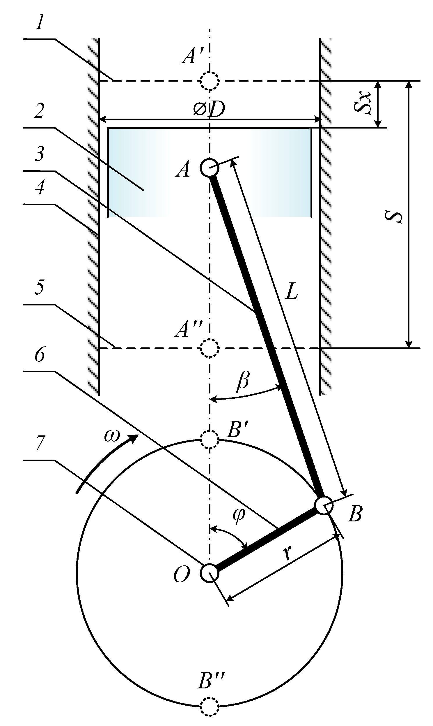
Figure 1 shows a piston compressor. When the rotation angle of the crank mechanism (
φ) equals 180° the piston is at the bottom dead center (BDC); when
φ = 0°, the piston is at the top dead center (TDC). The basic formula for calculating the instantaneous value of the torque on the electric motor shaft in the compressor motor system is as follows [
13]:
where
P is the pressure in the cylinder, Pa;
r is the radius of the crank, m;
T1 is the coefficient of the unit torque for the piston mechanism and
D is the piston diameter, m.
The pressure in the cylinder is determined from the PV diagram depending on the volume of the gas being compressed.
The distance between the piston and the BDC changes according to the following law of variation [
14]:
where
ω =
πn/30 is an angular rotation speed of the crank, c
−1;
λ =
r/L is a dimensionless parameter of the crank mechanism and the ratio of the crank radius to the length of the connecting rod.
The unit torque coefficient for a piston mechanism is the torque created by the compressor on the piston with a force of 1 N and a crank radius of 1 m [
15]:
where
β is the angle of deflection of the connecting rod axis, rad.
The angle of deflection of the connecting rod relative to the axis of the piston stroke depends on the position and parameters of the crank mechanism [
16]:
Substituting Equations (2)–(4) into Equation (1), it is possible to find the load torque of the compressor on the electric motor shaft for one compressor cycle.
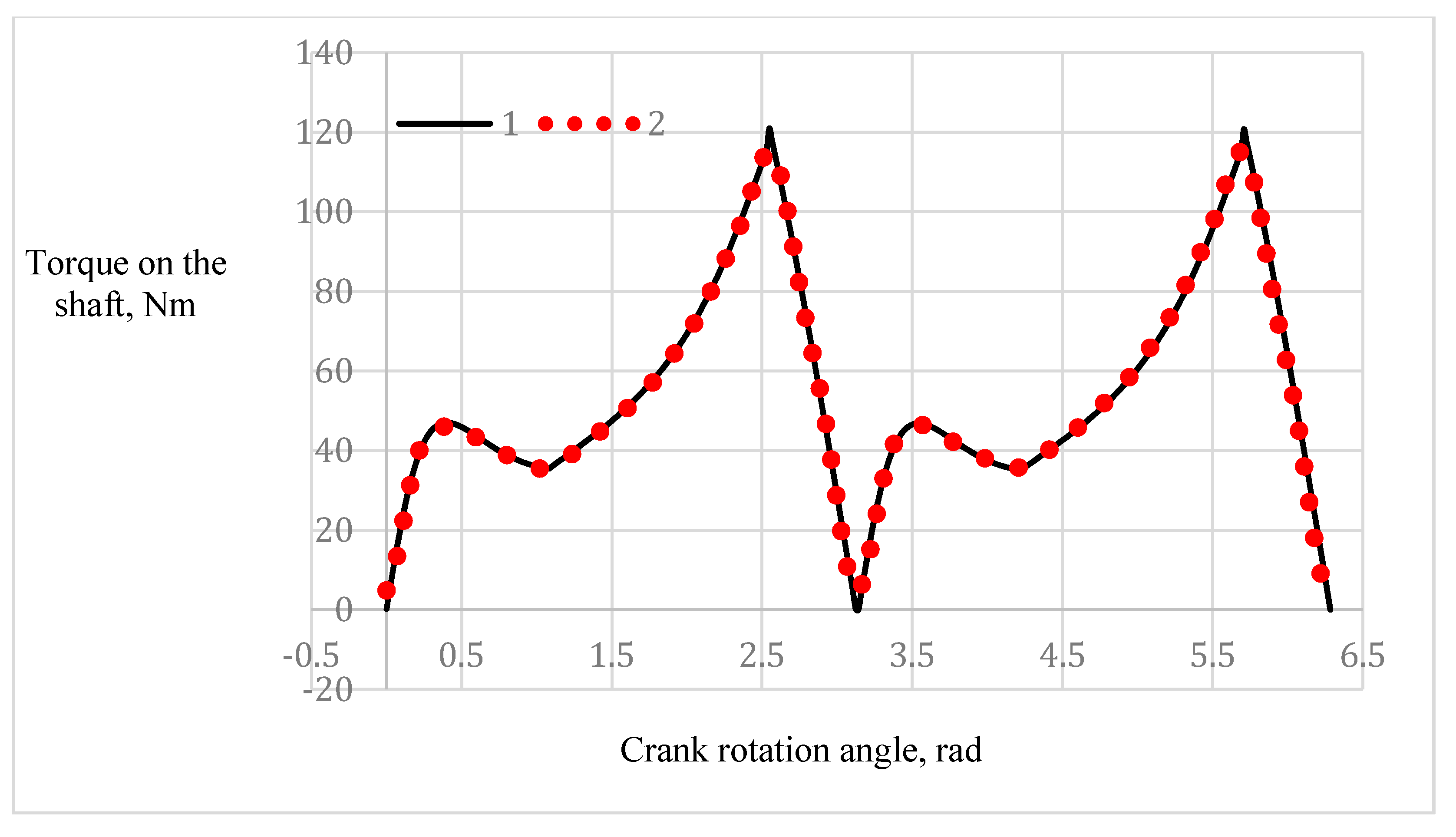
Figure 2 shows the PV diagram of a Bitzer 2CES-4Y-40S compressor for an R22 refrigerant at T = 273 K.
Figure 3 shows the load torque of a compressor Bitzer 2CES-4Y-40S from the rotation angle of the electric motor in the form of tabulated values (1) and Fourier series (2).
The load torque for a ship double-piston compressor Bitzer2CES-4Y-40S was found with the parameters presented below in
Table 1.
3. Mathematical Model and Decomposition.
The obtained characteristic is presented in the form of a tabulated value and does not have a mathematical description, which makes it impossible to use in further calculations.
Figure 2 shows that the obtained dependence was repeated with a certain periodicity. Thus, the obtained data could be replaced with an approximate mathematical model as a sum of harmonic functions [
7,
8,
9,
10,
11,
12]. To do this, we used the Fourier numerical decomposition. The load torque on the shaft was presented as follows (
Figure 2):
The standard deviation for the period of Formula (5) from the dependence shown in
Figure 2 (1) was 0.9981, which is permissible for use in electromechanics [
10,
11,
12].
To study the asynchronous motor of the compressor, an asynchronous electric motor BA132M4 was selected, with the parameters presented in
Table 2.
The study of the starting characteristics of the drive motor was carried out using a mathematical model. The plotting of the graphics of changes in the rotation speed and starting current when starting the electric drive was performed for different values of the moments of inertia on the shaft. The graphics could be plotted either without using a flywheel or with a flywheel of a constant and variable moment of inertia.
We then calculated the mechanical characteristics of an asynchronous electric drive of a double-piston ship compressor using the Kloss formula [
9,
10,
11]:
where
T was the moment on the motor shaft, N∙m;
Tmax was the critical torque of the electric motor, N∙m;
s was the slip and
sc was the critical slip of the electric motor.
The basic equation of the rotational motion dynamics is [
2,
3,
4,
5,
6,
7,
8]:
According to the adopted dual-mass system, the inertial forces of the moving masses were reduced to two forces. The first one was the inertia force of the piston masses (Pj) and the second was the centrifugal inertia force of the rotating masses (Kr).
For the central crank mechanism, the inertia force of piston masses was determined as the product of the mass (mj) and the piston acceleration with the sign reversed according to the formula:
Thus, the inertial force (Pj) could be represented as the sum of the first and second order inertia forces, which varied according to the harmonic law depending on the crank angle. The main extreme values of the inertia force (Pj), as well as the piston acceleration (jp), were at TDC and BDC. At TDC, the absolute value of the inertia force reached a maximum and at BDC, a minimum.
The inertia forces of the piston masses (
Pj) in the crank mechanism were presented as the free force (
Pj’) (
Figure 2), which acted along the cylinder axis and was equal to the force (
Pj), variable with respect to the magnitude and sign.
The connecting rod performed a complex plane-parallel movement in a plane perpendicular to the crankshaft axis. To determine the moment of inertia of the crankshaft, it was necessary to subtract the moment of inertia of the crankshaft nose and half of the moment of inertia of the crank journal from the value of Je, which could be found by calculation.
The moment of inertia of the knee with the crankshaft nose was determined by the formula:
where
a was the distance between the threads;
m was the mass of the part;
l was the length of threads;
B was the displacement of the center of gravity and
g was the acceleration of gravity.
The moment of inertia of the crankshaft nose was [
5,
6,
7,
8,
9]:
where
dn was the diameter of the crankshaft nose, m;
ln was the crankshaft nose length, m and
ρ was the density of the steel, kg/m
3.
The moment of inertia of half of the crank journal was:
where
dk was the diameter of the crank journal, m and
lk was the length of the crank journal, m.
Without a crank portion of a shaft, its moment of inertia can be found by calculation [
1,
2,
3,
4,
5]. The moment of inertia of the crank portion of a shaft when dividing it into four parts (two halves of the crank journal and the connecting rod journal without a counterweight and with a counterweight) was defined by the formula:
where
was the moment of inertia of the two halves of the crank journals;
Jsh was the moment of inertia of the connecting rod journal relative to the axis of the shaft rotation and
Jsh1 and
Jsh2 were the moments of inertia of the crankshaft web without a counterweight and with a counterweight.
When calculating the moment of inertia of a body relative to the axis of rotation parallel to the axis passing through the center of gravity and spaced from it at a distance
R, the well-known transition formula was used [
16]:
where
J‘sh was the moment of inertia of the connecting rod journal relative to the axis passing through the center of the shaft;
msh was the mass of the connecting rod journal, kg;
R was the crank radius, m;
dsh was the diameter of the connecting rod journal, m and
lsh was the length of the connecting rod journal, m.
The moment of inertia of the counterweight crank web could be found approximately by the formula:
where
J′sh2 was the polar moment of inertia of the parallel piped mass relative to the axis passing through the center of gravity;
msh2 was the crank web mass, kg and
l,
h2 and
b2 were the thickness, width and height of the crank web, kg.
We numerically solved the differential equation by the Runge–Kutta method of the Fourth Order using the following initial values:
The electromechanical characteristic was based on the dependence of the motor current on the slip:
where
I was the effective value of the current in the stator;
s was the slip;
λ was the overload capacity of the electric motor and
d1,
e1 and
F0 were the calculated coefficients for constructing the electromechanical characteristic [
15].
To assess the starting characteristics of the piston compressor electric drive, we used the following indicators: the time of the transient process
Tp and the relative magnitude of the speed and current ripple of the electric motor (Δ
w and Δ
I) in a steady-state:
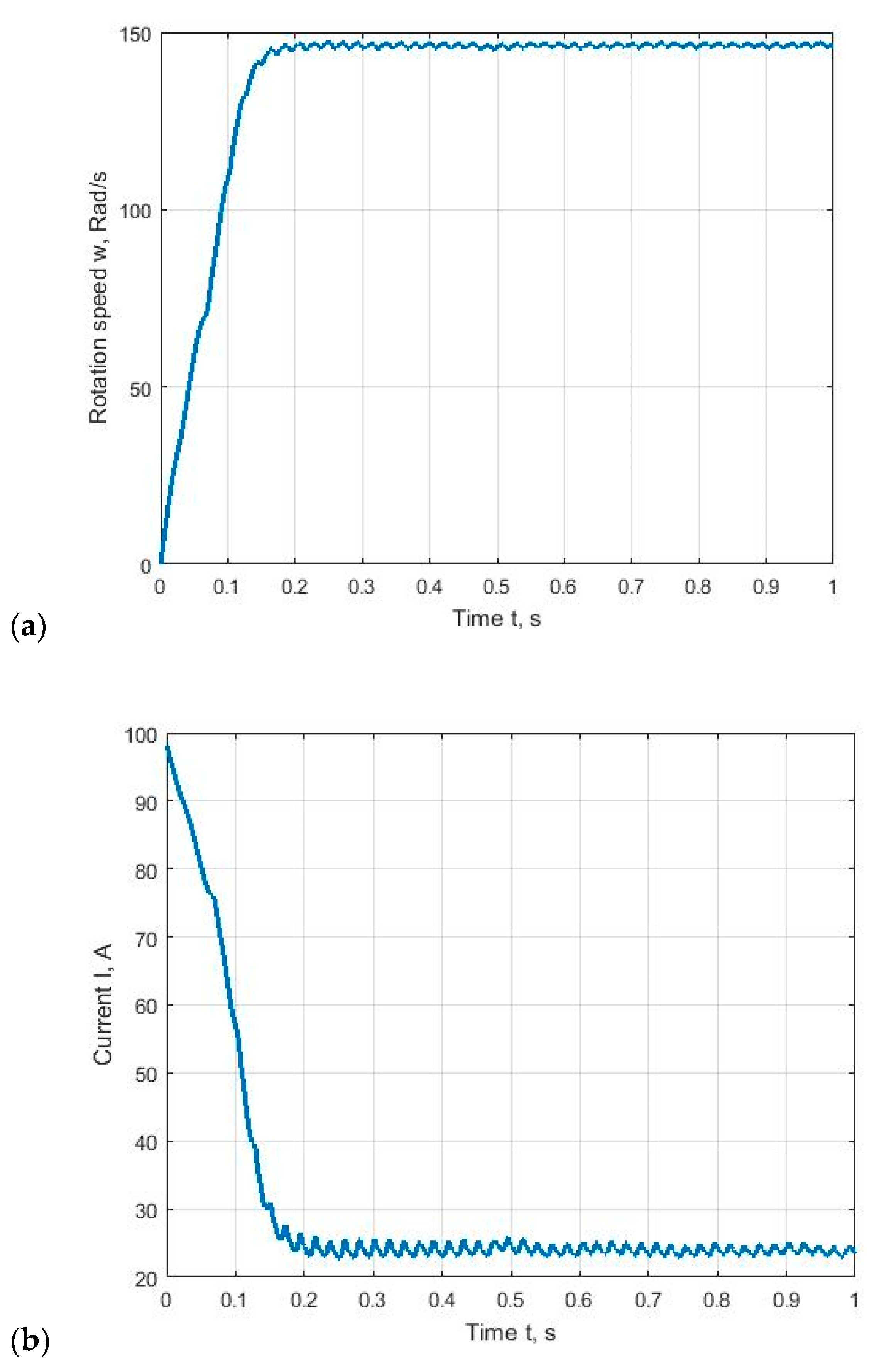
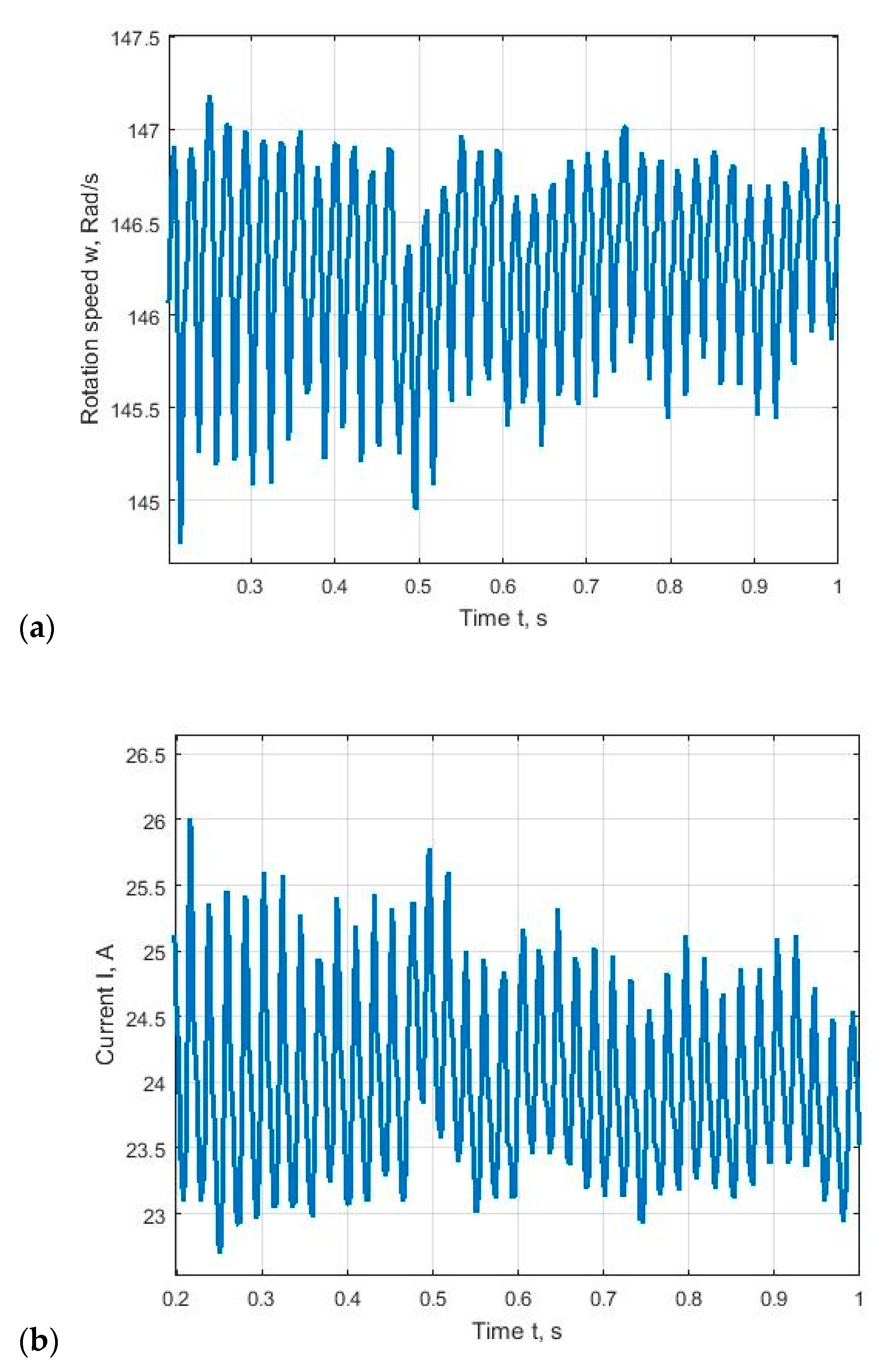
4. The Results of the Numerical Modeling
Mathematical modeling of the start of an electric drive with a flywheel was carried out in Mathcad and made it possible to plot graphics of transient processes of the rotation speed and current of the electric motor during its start-up (
Figure 3).
The graphics show that the start-up time (
Tp) of the electric motor to the rated speed was 0.215 s. Moreover, during the simulation, graphics of the speed and current pulsations were obtained in the steady-state operation of the electric drive under a periodically varying load (
Figure 4).
The assessment of the pulsation degree was made according to Formula (9). The starting time and ripple data are listed in
Table 3.
The ripples of the root mean square value of the current indicated the presence of current interharmonics in the piston compressor motor windings. To improve the efficiency of the electric drive, it was required to compensate for the detected current ripples.
With the existing ripples of the torque in the electric motor, proportional ripples of the stator electric current appeared. Ripple compensation was carried out using active filters or reactive power compensation. Depending on the load, the number of compressor pistons and the compressor motor rotation, the period of current and torque ripples in the overwhelming majority of cases would be a multiple of the fundamental harmonic thereby making it difficult to compensate. To reduce the ripple current for devices operating with a variable intermittent load such as compressors and pumps, it is advisable to use active harmonic filters with a fixed filtration or with an automatic adjustment of filtration parameters. The development of a device capable of a real-time compensation of a current ripple on the basis of the selected ripple will be a further study.
Listing and photo (
Figure 5) of the program code for signaling identification [
16] errors for ship equipment:
COMM ERR BETW. ACP/BR - ESU CAN A FAIL
COMM ERR BETW. ACP/BR - RPMU1 CAN A FAIL
COMM ERR BETW. ACP/BR - RPMU2 CAN A FAIL
COMM ERR BETW. ACP/BR - RAI CAN A FAIL
COMM ERR BETW. ACP/BR - DGU CAN A FAIL
COMM ERR BETW. ACP/BR - MEI CAN A FAIL
COMM ERR BETW. ACP/BR - C2LOC CAN A FAIL
COMM ERR BETW. ACP/BR - LTU BR CAN A FAIL
COMM ERR BETW. ACP/BR - LTU ECR CAN A FAIL
COMM ERR BETW. ACP/BR - PBT CAN A FAIL
COMM ERR BETW. ACP/BR - MPP ECR CAN A FAIL
COMM ERR BETW. ACP/BR - ACP-ECR CAN A FAIL
COMM ERR BETW. ACP/BR - RDO CAN A FAIL
COMM ERR BETW. ACP/BR - DGU SIO CAN A FAIL
As can be seen from
Figure 5. the system also incorrectly set the servo motor setting. The telegraph knob was set to 0 and the system gave a setpoint of approximately 32 turns. This failure was associated with the desynchronization of the potentiometric sensor installed in the telegraph handle or a jump in the pulse current in the processing area of the CAN bus data.
To restore the correct operation of the system, it was necessary to calibrate the ECR LTU lever. The calibration algorithm is shown below. Calibration should be done with the engine stopped and blocked by start or by bridge command. With the engine running and the current lever in the command, any manipulations are prohibited.


