Article

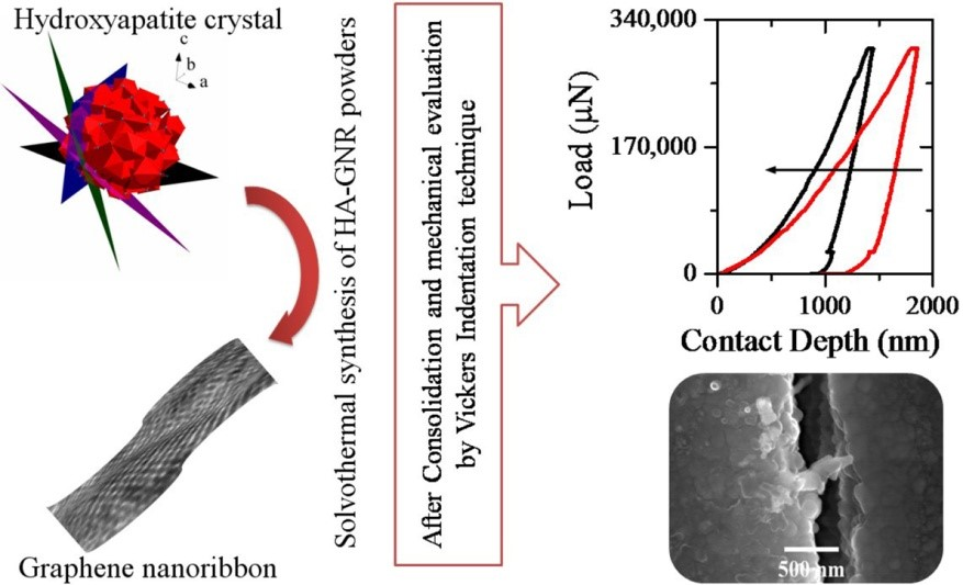
Synthesis of Graphene Nanoribbons–Hydroxyapatite Nanocomposite Applicable in Biomedicine and Theranostics

by
Hassan Nosrati
1,
Rasoul Sarraf-Mamoory
1,*,
Amir Hossein Ahmadi
2 and
Maria Canillas Perez
3
1
Department of Materials Engineering, TarbiatModares University, Tehran P.O. Box 14115-111, Iran
2
Department of Basic Science, Shahed University, Tehran P.O. Box 18155/159, Iran
3
Instituto de Cerámica y Vidrio, CSIC, 28006 Madrid, Spain
*
Author to whom correspondence should be addressed.
J. Nanotheranostics 2020, 1(1), 6-18; https://0-doi-org.brum.beds.ac.uk/10.3390/jnt1010002
Submission received: 12 February 2020 / Revised: 16 April 2020 / Accepted: 17 April 2020 / Published: 22 April 2020

Abstract

:
In order to investigate the effect of graphene nanoribbons on the final properties of hydroxyapatite-based nanocomposites, a solvothermal method was used at 180 °C and 5 h for the synthesis of graphene nanoribbons–hydroxyapatite nanopowders by employing hydrogen gas injection. Calcium nitrate tetrahydrate and diammonium hydrogenphosphate were used as calcium and phosphate precursors, respectively. To synthesize the powders, a solvent containing diethylene glycol, anhydrous ethanol, dimethylformamide, and water was used. Graphene oxide nanoribbons were synthesized by chemical unzipping of carbon nanotubes under oxidative conditions. The synthesized powders were consolidated by spark plasma sintering methodat 950 °C and a pressure of 50 MPa. The powders and sintered samples were then evaluated using X-ray diffraction, Raman spectroscopy, high-resolution transmission electron microscopy, Vickers microindentation techniques, and biocompatibility assay. The findings of this study showed that the final powders synthesized by the solvothermal method had calcium to phosphate ratio of about 1.67. By adding a small amount of graphene nanoribbon (0.5%W), elastic modulus and hardness of hydroxyapatite increased dramatically. In biological experiments, the difference of hydroxyapatite effect in comparison with the nanocomposite was not significant. The findings of this study showed that graphene nanoribbons have a positive effect on the properties of hydroxyapatite, and these findings would be useful for the medical and theranostic application of this type of nanocomposites.

Graphical Abstract

1. Introduction

Hydroxyapatite (HA, a member of the calcium phosphate family) has poor mechanical properties. The most important of these properties are low fracture toughness (fracture toughness of less than 1 MPa.m0.5), intrinsic brittleness, poor tensile strength, and weak wear resistance [1,2,3,4]. However, despite these poor mechanical properties, HA has excellent biological properties, including bone bonding ability, excellent biocompatibility, highly compatible with living bone tissues, scaffolding properties, and osteoconductive properties [5,6,7,8,9,10]. These properties have made HA widely used in biomedical applications. Therefore, many methods have been employed to synthesize this bioceramic, such as combustion preparation, electrochemical deposition, hydrolysis, precipitation, sputtering, multiple emulsion, solid-state reaction, biomimetic deposition, solvothermal method, sol–gel, and hydrothermal process [11,12,13,14,15,16,17,18,19,20,21,22,23], which have led to diverse morphologies such as ribbons, rods, wires, and tubes [24,25,26,27,28,29]. However, to eliminate mechanical weaknesses, researchers have used different reinforcing materials. Among the materials used, carbon nanomaterials such as carbon nanotubes (CNTs), graphene, graphene oxide, and graphene nanoribbons (GNRs) have received more attention than others [30,31,32]. The most important reason is the biocompatibility and high mechanical properties of these materials. Graphene with honeycomb structure, excellent mechanical properties, and high specific surface area has been studied more than carbon nanotubes [33,34,35,36,37,38].
The results of investigations showed that the addition of graphene sheets to HA greatly improved its mechanical and biological properties [39,40]. However, the excessive addition of graphene sheets has reduced the mechanical properties, because graphene sheets fold up and prevent high relative densities [41]. One way to control this weakness is to use GNRs instead of graphene sheets. GNRs have been used in some research to enhance the properties of HA. GNRs are synthesized in various ways. One of these methods is the use of carbon nanotubes. Unzipping CNTs create GNRs [42]. However, for the use of carbon nanomaterials as a reinforcement phase, the surface of these materials must contain chemical agents, such as graphene oxide surface. Published research has also used materials such as graphene oxide. Graphene oxide is reduced by methods such as the hydrothermal process, and its mechanical properties are improved [43,44]. Unzipping the CNTs chemically also makes graphene oxide nanoribbons (GONRs) [42].
One of the best methods for the synthesis of hybrid powders containing HA is hydrothermal (solvothermal) process. In this method, the precursor containing the calcium ions is first added to the solution containing carbon nanomaterials. The solution containing phosphate ions is then added to the previous solution. In this way, calcium phosphate powders precipitate as white powders. These powders are then transferred to a hydrothermal autoclave and the process is performed. During the hydrothermal process, these primary powders dissolve at high temperatures and begin nucleation and growth of HA. Nucleation of HA crystals is formed on the surface agents of carbon nanomaterials by van der Waals forces [40,43,44]. In some published studies, ultrasound operations have been used to reduce the particles size of the synthesized HA [45]. For hydrothermal process, reducing the size of the initial powders by ultrasound effects will cause them to dissolve more rapidly in the hydrothermal process, increasing the reaction kinetics and enhancing the quality of the final powders.
Based on the above, in this study, GNRs were used to enhance the mechanical properties of HA. GONRs have been used for this purpose. For the synthesis of hybrid powders, the hydrothermal method under hydrogen gas pressure has been used. To improve the properties of the synthesized powders, ultrasound operations have been used. The synthesized powders were sintered by spark plasma sintering (SPS) method. Synthesized powders and consolidated samples were characterized by various methods, including X-ray diffraction (XRD), Raman spectroscopy, high-resolution transmission electron microscopy (HR-TEM), and Vickers indentation technique. So far, a lot of research has been done on the applications of HA and graphene materials in the field of theranostics, which confirms the capabilities of these materials in this field [46,47,48,49,50,51]. Given that each phase of the nanocomposite has the potential to be used in biomaterials and theranostics, the synthesized nanocomposite is expected to be usable in biological and theranostic applications.

2. Materials and Methods

The primary chemicals used in this study, along with their specifications, are presented in Table 1. The specifications of the CNTs, the materials used in the GONRs synthesis section, and the results obtained are exactly the same as the reference used [42]. The initial solution (S1) was first prepared (DI water + DEG+ DMF+ anhydrous ethanol with a volume ratio of 40:20:20:20), and the following steps were performed in order. 4.7 g of calcium nitrate tetrahydrate in 120 mL of S1 was added dropwise to a 20 mL stirred suspension of GONR (3.13 mg/mL) (HA/0.5% rGONR) with stirring continued for 1 h.1.56 g of diammonium hydrogenphosphate in 80 mL of S1 was dropwise added to the solution, and the pH of the resulted solution was adjusted to >10 with ammonium solution.The suspension was sonicated for 1h (Irradiation power of 140W, A QSONICAQ700 sonicator with a maximum power output of 700W was employed for the ultrasonic irradiation).The resulting solution was poured into the Teflon (PTFE) vessel and transferred to the autoclave. The solvothermal process was carried out for 5 h at 180 °C by injection of hydrogen gas at 10 bar (the volume of the PTFE container was 340 mL and the total pressure was 23 bar). The powders were dried at oven for 12 h at 60 °C. After drying and ball milling (250 rpm, 12 h), the powders were consolidated via SPS.To compare the effect of reduced GONR on the final properties, a pure HA powders sample was synthesized under similar conditions.

2.1. Evaluation of the SinteredSamples

As previously reported [52], sintering of the powders was performed at 950 °C. The biocompatibility assays were performed exactly similar to the previous report [52]. The Archimedes method was used to calculate the relative density of sintered samples (ASTM C373-88).

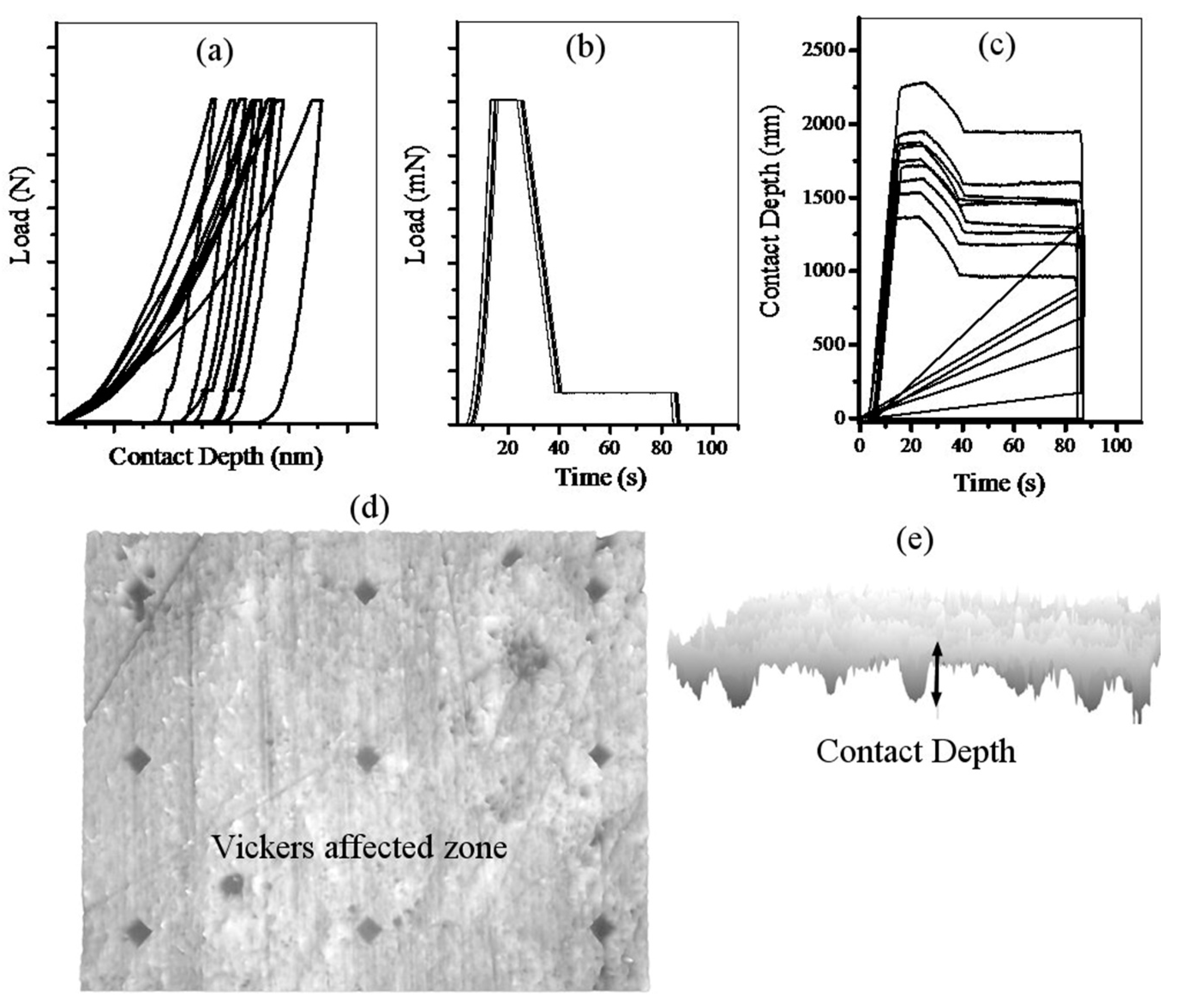
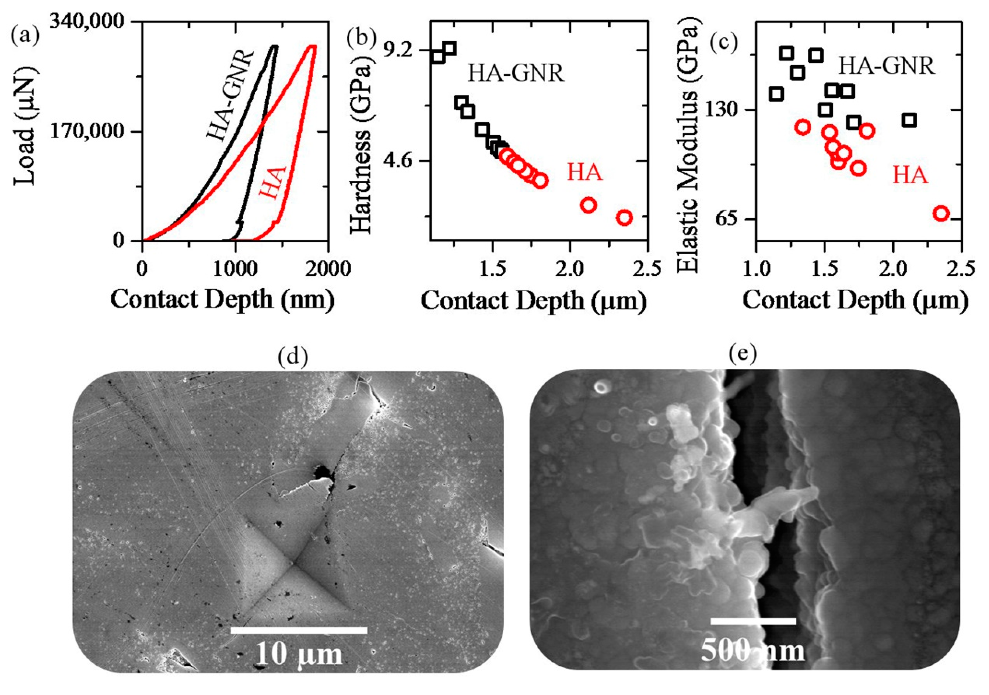
2.2. Vickers Indentation

Grindosonic tester with a Vickers tip was conducted on the polished surfaces of samples at a maximum load of 300 mN (ramp dwell time of 10 s). Nine tests were performed at different locations of each sample. Elastic modulus and hardness were calculated from the load-displacement curves using Olive–Pharr method [53]. Figure 1 shows load-displacement diagram, load-time, contact depth-time diagrams, indentation affected zone, and contact depth profile for this test. The results were statistically evaluated by the Kernel Density Estimation method [54,55].

2.3. Characterization Techniques

Diamond 3.2 and Imagej 1.52d softwares were used in this study. Different evaluation methods have been used in this research, some of which are described below. The other instruments used to characterize the samples include inductively coupled plasma (ICP) (DV7300, Optima Co.), and portable scanning electron microscope (SEM, TM-1000).

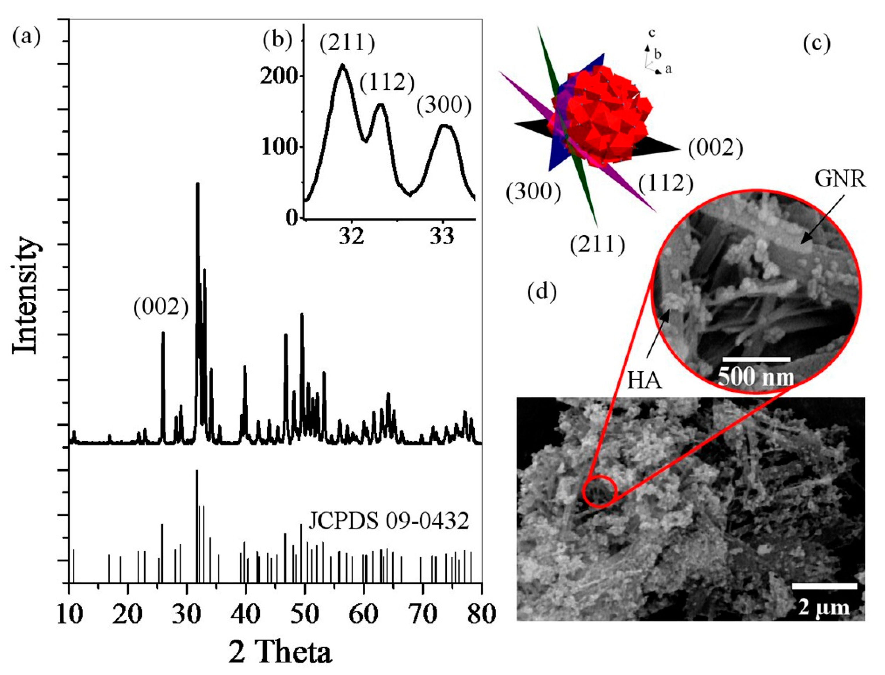
2.3.1. X-Ray Diffraction

XRDwas used to determine the phase constituents of the samples (X’ Pert Pro, Panalytical Co., contained a detector Cu Kα radiation, λ = 1.5406 Å, 40 kV, 40 mA, 2 theta scanning range from 10° up to 80° in steps of 0.02°). Equation (1) was used to estimate the crystallinity of HA (Xc) [56].
x c = 1 ν ( 112 / 300 ) I 300
where ν(112/300) and I300 are the intensity of the hollow between diffraction peaks of HA in the planes (300) and (112) and the intensity of the peak of HA in the plane (300), respectively. Equation (2) was used to calculate the crystallite size (Williamson–Hall method) [57].
β cos θ = 0.9 λ d + 4 ε sin θ
In this equation, d, θ, and λ are grain size, Bragg diffraction angle, and wave length of used X-ray (Cu), respectively. β and ε are full width at half height (FWHM), and crystalline lattice strain, respectively.

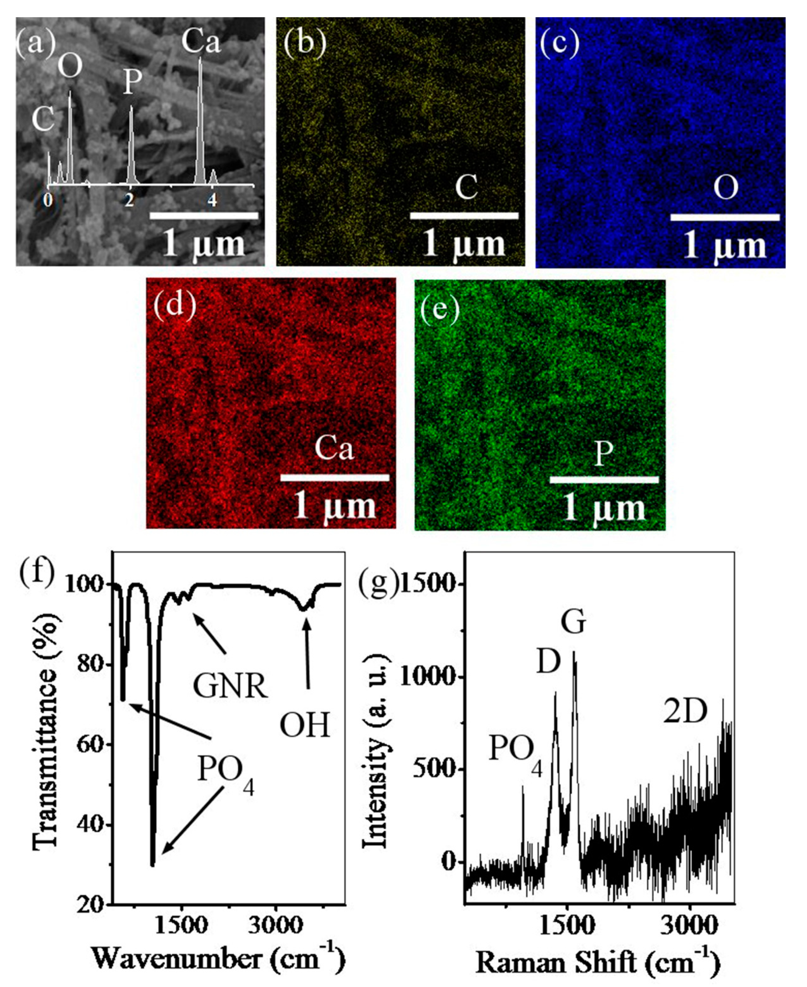
2.3.2. Field Emission Scanning Electron Microscopy

FESEM (Hitachi, Düsseldorf, Germany, S4700 equipped with energy dispersive X-ray spectroscopy) was used to observe the morphology of the samples (mounted in an adhesive carbon film and Au coated by sputtering for its observation).

2.3.3. Fourier Transform Infrared Spectroscopy

Fourier transform infrared spectroscopy (FTIR, VERTEX 70, Bruker Corp., Billerica, MA, USA) was used to identify the functional groups of the samples (resolution of 4 cm−1, scan number of 8, spectral region from 400 to 4000 cm−1 using 2 cm−1 steps). The samples were prepared and mixed with potassium bromide (KBr, 1 mg powdered samples and 300 mg KBr). The mixture was pressed into discs by applying 200 MPa pressures (1 mm thickness). The spectra were collected at room conditions (60% relative humidity).

2.3.4. Raman Spectroscopy

Renishaw inVia (Wotton-under-Edge, UK) spectrometer was used in the range of 300–3500 cm−1, recording five times for 10 s of each accumulation, with a wavelength of 532 nm, green laser line that had been excited from an argon ion laser in a backscattering configuration using a microscope with a 100× objective, 100% power (an acquisition time of 10 s). An optical microscope was used with the Raman spectrometer. In order to remove the fluorescence background, the samples were subjected on Al foil.

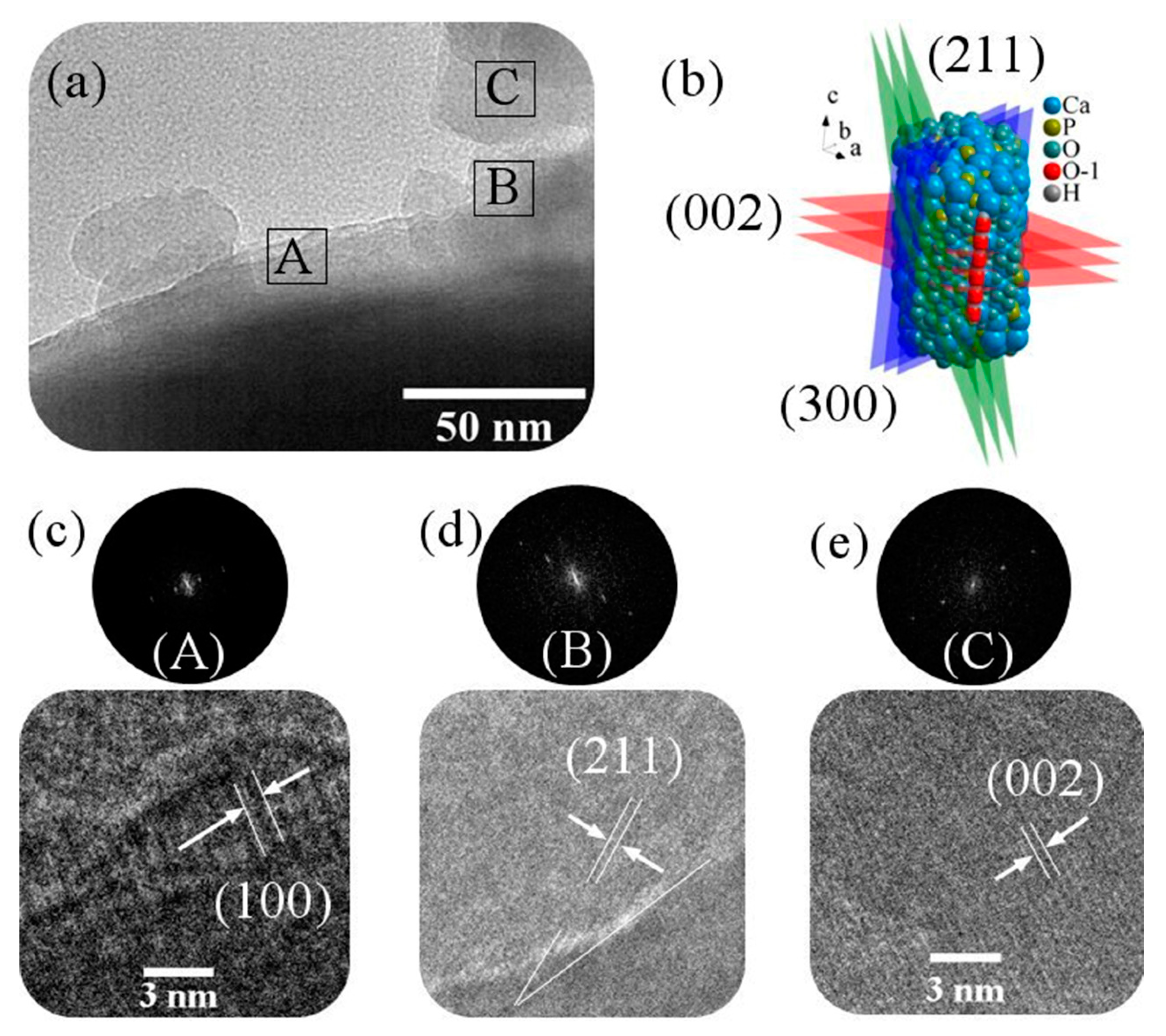
2.3.5. High-Resolution Transmission Electron Microscopy

TALOS F200A with a twin lens system(X-FEG electron source, Ceta 16M camera and a super-X EDS detector) was used to observe atomic structure of the samples and spatially resolved elemental analysis, with a spatial resolution higher than 2 nm. To study the atomic structure, fast fourier transform (FFT) and inverse fast fourier transform (IFFT) analysis were used.

3. Results and Discussion

Figure 2 shows the XRD pattern of GNR-HA powders, HA crystal planes, and FESEM images of GNR-HA powders. According to the XRD pattern of the synthesized powders (Figure 2a), full conformity is achieved between the reference standard of pure HA (JCPDS 09-0432) and the peaks obtained [52]. Accordingly, the HA has a high purity hexagonal structure. In other words, the XRD pattern of the GNR-HA powders is quite similar to pure HA. GONR has a peak in the range of 2θ=10 ((001) peak). After reduction of GONR, this peak is removed and a new one ((002) peak) appears around 2θ = 26. This peak is much weaker and wider than the HA (002) peak (it is shorter in intensity, and its diffraction angle covers a larger range) due to the amorphous structure of reduced GONR [42,56]. Therefore, this peak is covered by the HA (002) peak, which is highly intensified due to its high crystallinity. Table 2 shows the specification of the HA scatter planes obtained. According to the XRD pattern, <300>, <211>, and <002> directions are the main growth directions in HA crystals, where (002) and (300) planes are perpendicular (Figure 2b,c). It is clear that injection of a gas of and thus an increase in total autoclave pressure will increase the crystallinity from to 86% (Equation (1)) and crystallite size to 28 nm (Equation (2)). As shown in the FESEM image (Figure 2d), the HA particles have agglomerated in some places. It is clear that morphology of these particles is nanorod-shaped. These nanorods are less than 50 nanometers in diameter. As with similar reports previously published, here is the direction of the growth of nanorods in the C-axis. Additionally, these images confirm the presence of GNRs in the powders. The size of the HA particles is smaller than that of samples synthesized under similar conditions without ultrasound treatment. The reason for this is the use of ultrasound irradiation [40,43,58,59].
Figure 3 shows the EDS analysis, elemental mapping, FTIR analysis, and Raman spectroscopy for GNR-HA powders. Elemental mapping for synthesized powders confirm the homogeneous distribution of calcium, phosphorous, oxygen, and carbon elements, which is aligned with the EDS analysis. At the end of the solvothermal process, some of the residual solution was controlled by ICP analysis. The amount of elements checked in the ICP analysis were very low and negligible, and the calcium to phosphate ratio in the inputs was about 1.67 and. ICP results and homogeneous element maps confirm the 1.67 ratio of calcium to phosphate for the final product [56]. Figure 5 shows FTIR analysis and Raman spectroscopy for synthesized powders and GO. The peak at 565 cm−1 is related to P–O bending in HA. The peaks at 925, 1035, and 1095 cm−1 are related to P–O(H) stretching vibration in HA. The peak at1055 cm−1 is related to C–O stretching vibration in GONR. The peak at 1230 cm−1 is related to C–OH stretching vibration in GONR. The peak at1395 cm−1 is related to C–O–H deformation vibration in GONR. The peak at 1620 cm−1 is related to C=C stretching vibration in GONR. The peak at 1730 cm−1 is related to C=O stretching vibration in GONR. The peak at 3400−3500 cm−1 is related to O–H stretching vibration in HA and GONR. The FTIR analysis reveals that the synthesized powders contain GNR and HA. By comparing the GONR peaks with the final GNR-HA powders peaks, it is found that the bonds related to the oxygen-containing functional groups on the GONR surface have reduced well and some of the peaks have completely disappeared. The peaks at 1395 cm−1 and 1730 cm−1 are shifted upwards, indicating reduction of GONR, since these two peaks are characteristic of GONR [40,41,42,43,44,60,61,62].
The Raman spectroscopy has been done to confirm the presence of reduced GONR.v1, PO43− (P–O) is symmetric stretching peaks in HA located at 962 cm−1. D bond is related to the symmetric oscillations of the A1g of carbon atoms with the SP3 hybrid in GNR located at 1350 cm−1. G bond is related to the shaking of the E2g of carbon atoms phonon with the sp2 hybrid in GNR located at 1600 cm−1. 2D peak is related to the number of layers of the GNR located at 2700 cm−1. The rGONR-related Raman signals in this spectrum are much clearer than the HA signal, although its weight percent in the powders is much lower [40,41,42,43,44]. Compared to peaks related to pure HA synthesized in the same way, some displacement is observed in these peaks, which is probably related to the applied gas pressure [63].
Figure 4 illustrates the HRTEM image with the FFT and IFFT analysis of composite powders. Three areas were considered in the HRTEM image (Figure 4a). As the analysis of region A shows (Figure 4c), the (100) planes are marked with the d-spacing. In region B (Figure 4d), the HA particles grow along the (211) planes and show a d-spacing of 0.28 nm. In region C (Figure 4e), the HA particles grow along the (002) planes and show a d-spacing of 0.34 nm. According to the schematic images (Figure 4b), the atomic alignment of the crystalline planes with GNR surface is less than the limit (0.25). Therefore, the interface between the two phases on the GNR surface is likely coherent. According to these findings, (300) planes are likely in contact with the surface of GNR. In this research, during the synthesis of HA, its (300) planes are prior to the (100) planes [41,64].
Density calculations from the Archimedes method showed that GNR-HA nanocomposite and pure HA reached to relative densities of 97.11% and 98.3%, respectively. Figure 5 shows the force-displacement diagrams of the sintered samples along with the mechanical properties extracted from these diagrams, FESEM image of Vickers affected zone for GNR-HA nanocomposite, and FESEM image of nanostructure and Vickers crack after sintering for GNR-HA and indentation. As the curves show, the contact depth for pure HA is greater than that for GNR-HA sample. In other words, more force is needed to achieve a constant contact depth in GNR-HA. According to these diagrams, the elastic work in pure HA is greater than the GNR-HA sample. Additionally, the plastics work is slightly higher in pure HA, but with a smaller ratio, which is obtained from the surface below the curves. In these diagrams, the transition to the left means the improvement of mechanical properties. The indentation analysis results show that the hardness, and the Young’s modulus of GNR-HA sample, are higher than that of pure HA. Figure 5d,e shows the FESEM images of cracks formed during mechanical analysis on sintered samples. GNRs have increased the samples fracture toughness with GNRs pull-out and GNRs bridging mechanisms. The GNR’s pull out energy is much higher than the energy needed to pull out of HA from each other, because GNRs have a higher specific surface area [40,41].
Figure 6 shows the statistical analysis of elastic modulus and hardness for GNR-HA nanocomposite and pure HA. This analysis shows how the mechanical behaviors of HA change with the addition of small amounts of GNRs.
Figure 7 shows fluorescent cell culture images on composite sample after 72 h and results of the MTT (colorimetric assay for assessing cell metabolic activity) assay. It can be concluded that the leached obtained showed no significant toxicity to the osteoblasts culture (over a 7-day period). The only difference with the previously published work [52] is the morphology of the cells that are globular. The presence of GNR, which has become hydrophobic by the loss of its surface agents, may have caused this change.

4. Conclusions

The findings of this study showed that the final powders synthesized by solvothermal method had a calcium-to-phosphate ratio of about 1.67. In biological experiments, the difference of HA effect in comparison with rGONR-HA was not significant. The results of this study would be appropriate for biomedicine use of this nanocomposite. By adding a small amount of graphene nanoribbon (0.5%W), elastic modulus and hardness of hydroxyapatite increased dramatically. GNRs have increased the samples’ fracture toughness with GNR pull-out and GNR bridging mechanisms. According to the HRTEM findings, (300) planes are likely in contact with the surface of GNR. Density calculations from the Archimedes method showed that GNR-HA nanocomposite and pure HA reached to relative densities of 97.11% and 98.3%, respectively. The results of mechanical analysis showed that in some parts of the nanocomposite, the hardness reached above 9 GPa and the elastic modulus reached above 140 GPa.

Author Contributions

Conceptualization, H.N. and R.S.-M.; methodology, R.S.-M.; software, A.H.A.; validation, R.S.-M.; formal analysis, A.H.A.; investigation, H.N.; resources, M.C.P.; data curation, M.C.P.; writing—original draft preparation, H.N.; writing—review and editing, H.N.; supervision, R.S.-M., M.C.P. All authors have read and agreed to the published version of the manuscript.

Funding

This research received no external funding.

Conflicts of Interest

The authors declare no conflict of interest.

References

  1. Li, M.; Xiong, P.; Yan, F.; Li, S.; Ren, C.; Yin, Z.; Li, A.; Li, H.; Ji, X.; Zheng, Y.; et al. An overview of graphene-based hydroxyapatite composites for orthopedic applications. Bioact. Mater. 2018, 3, 1–18. [Google Scholar] [CrossRef] [PubMed]
  2. Gao, C.; Feng, P.; Peng, S.; Shuai, C. Carbon nanotube, graphene and boron nitride nanotube reinforced bioactive ceramics for bone repair. Acta Biomater. 2017, 61, 1–20. [Google Scholar] [CrossRef] [PubMed]
  3. Ahmadi, A.H.; Nosrati, H.; Sarraf-Mamoory, R. Decreasing β- three calcium phosphate particle size using graphite as nucleation sites and diethylene glycol as a chemical additive. J. Bioeng. Res. 2019, 1, 50–59. [Google Scholar]
  4. Nosrati, H.; Le, D.Q.S.; Emameh, R.Z.; Bunger, C.E. Characterization of the precipitated Dicalcium Phosphate Dehydrate on the Graphene Oxide surface as a bone cement reinforcement. J. Tissues Mater. 2019, 2, 33–46. [Google Scholar]
  5. Gholibegloo, E.; Karbasi, A.; Pourhajibagher, M.; Chiniforush, N.; Ramazani, A.; Akbari, T.; Bahador, A.; Khoobi, M. Carnosine-graphene oxide conjugates decorated with hydroxyapatite as promising nanocarrier for ICG loading with enhanced antibacterial effects in photodynamic therapy against Streptococcus mutans. J. Photochem. Photobiol. B: Boil. 2018, 181, 14–22. [Google Scholar] [CrossRef]
  6. Iafisco, M.; Di Foggia, M.; Bonora, S.; Prat, M.; Roveri, N. Adsorption and spectroscopic characterization of lactoferrin on hydroxyapatite nanocrystals. Dalton Trans. 2011, 40, 820–827. [Google Scholar] [CrossRef]
  7. Tavafoghi, M.; Brodusch, N.; Gauvin, R.; Cerruti, M. Hydroxyapatite formation on graphene oxide modified with amino acids: Arginine versus glutamic acid. J. R. Soc. Interface 2016, 13, 20150986. [Google Scholar] [CrossRef]
  8. Zhang, R.; Metoki, N.; Sharabani-Yosef, O.; Zhu, H.; Eliaz, N. Hydroxyapatite/Mesoporous Graphene/Single-Walled Carbon Nanotubes Freestanding Flexible Hybrid Membranes for Regenerative Medicine. Adv. Funct. Mater. 2016, 26, 7965–7974. [Google Scholar] [CrossRef]
  9. Nosrati, H.; Sarraf-Mamoory, R.; Le, D.Q.S.; Bünger, C.E. Enhanced fracture toughness of three dimensional graphene-hydroxyapatite nanocomposites by employing the Taguchi method. Compos. B Eng. 2020, 190, 107928. [Google Scholar] [CrossRef]
  10. Moldovan, M.; Prodan, D.; Sarosi, C.; Carpa, R.; Socaci, C.; Rosu, M.-C.; Pruneanu, S.M. Synthesis, morpho-structural properties and antibacterial effect of silicate-based composites containing graphene oxide/hydroxyapatite. Mater. Chem. Phys. 2018, 217, 48–53. [Google Scholar] [CrossRef]
  11. Canillas, M.; Rivero, R.; García-Carrodeguas, R.; Barba, F.; Rivas-Mercury, J.; Garcia-Carrodeguas, R.; Rodriguez, M.A. Processing of hydroxyapatite obtained by combustion synthesis. Boletín de la Sociedad Española de Cerámica y Vidrio 2017, 56, 237–242. [Google Scholar] [CrossRef]
  12. Guo, X.; Yan, H.; Zhao, S.; Li, Z.; Li, Y.; Liang, X. Effect of calcining temperature on particle size of hydroxyapatite synthesized by solid-state reaction at room temperature. Adv. Powder Technol. 2013, 24, 1034–1038. [Google Scholar] [CrossRef]
  13. Shirkhanzadeh, M. Direct formation of nanophase hydroxyapatite on cathodically polarized electrodes. J. Mater. Sci. Mater. Electron. 1998, 9, 67–72. [Google Scholar] [CrossRef] [PubMed]
  14. Jillavenkatesa, A.; Sr, R.A.C. Sol–gel processing of hydroxyapatite. J. Mater. Sci. 1998, 33, 4111–4119. [Google Scholar] [CrossRef]
  15. Kuriakose, T.; Kalkura, S.N.; Palanichamy, M.; Arivuoli, D.; Dierks, K.; Bocelli, G.; Betzel, C. Synthesis of stoichiometric nano crystalline hydroxyapatite by ethanol-based sol–gel technique at low temperature. J. Cryst. Growth 2004, 263, 517–523. [Google Scholar] [CrossRef]
  16. Sinitsyna, O.V.; Veresov, A.G.; Kovaleva, E.S.; Kolen’Ko, Y.V.; Putlyaev, V.I.; Tretyakov, Y.D. Synthesis of hydroxyapatite by hydrolysis of α-Ca3(PO4)2. Russ. Chem. Bull. 2005, 54, 79–86. [Google Scholar] [CrossRef]
  17. Liu, C.; Huang, Y.; Shen, W.; Cui, J. Kinetics of hydroxyapatite precipitation at pH 10 to 11. Biomaterials 2001, 22, 301–306. [Google Scholar] [CrossRef]
  18. Manuel, C.M.; Ferraz, M.P.; Monteiro, F.J. Synthesis of hydroxyapatite and tri calcium phosphate nanoparticles Preliminary Studies. Key Eng. Mater. 2003, 240–242, 555–558. [Google Scholar] [CrossRef]
  19. Yamashita, K.; Arashi, T.; Kitagaki, K.; Yamada, S.; Umegaki, T.; Ogawa, K. Preparation of Apatite Thin Films through rf-Sputtering from Calcium Phosphate Glasses. J. Am. Ceram. Soc. 1994, 77, 2401–2407. [Google Scholar] [CrossRef]
  20. Kimura, I. Synthesis of Hydroxyapatite by Interfacial Reaction in a Multiple Emulsion. Res. Lett. Mater. Sci. 2007, 2007, 1–4. [Google Scholar] [CrossRef] [Green Version]
  21. Tas, A.C. Synthesis of biomimetic Ca-hydroxyapatite powders at 37 °C in synthetic body fluids. Biomaterials 2000, 21, 1429–1438. [Google Scholar] [PubMed]
  22. Qi, C.; Zhu, Y.-J.; Ding, G.-J.; Wu, J.; Chen, F. Solvothermal synthesis of hydroxyapatite nanostructures with various morphologies using adenosine 5′-monophosphate sodium salt as an organic phosphorus source. RSC Adv. 2015, 5, 3792–3798. [Google Scholar] [CrossRef]
  23. Neira, I.S.; Kolen’Ko, Y.V.; Lebedev, O.I.; Van Tendeloo, G.; Gupta, H.S.; Guitián, F.; Yoshimura, M. An Effective Morphology Control of Hydroxyapatite Crystals via Hydrothermal Synthesis. Cryst. Growth Des. 2009, 9, 466–474. [Google Scholar] [CrossRef]
  24. Peng, F.; Yu, X.; Wei, M. In vitro cell performance on hydroxyapatite particles/poly(l-lactic acid) nanofibrous scaffolds with an excellent particle along nanofiber orientation. Acta Biomater. 2011, 7, 2585–2592. [Google Scholar] [CrossRef] [PubMed]
  25. Jevtić, M.; Mitrić, M.; Škapin, S.; Jančar, B.; Ignjatović, N.L.; Uskoković, D.P. Crystal Structure of Hydroxyapatite Nanorods Synthesized by Sonochemical Homogeneous Precipitation. Cryst. Growth Des. 2008, 8, 2217–2222. [Google Scholar]
  26. Costa, D.O.; Dixon, S.J.; Rizkalla, A. One- and Three-Dimensional Growth of Hydroxyapatite Nanowires during Sol–Gel–Hydrothermal Synthesis. ACS Appl. Mater. Interfaces 2012, 4, 1490–1499. [Google Scholar] [CrossRef]
  27. Zhang, Y.; Lu, J.; Wang, J.; Yang, S.; Chen, Y. Synthesis of nanorod and needle-like hydroxyapatite crystal and role of pH adjustment. J. Cryst. Growth 2009, 311, 4740–4746. [Google Scholar] [CrossRef]
  28. Chandanshive, B.B.; Rai, P.; Rossi, A.; Ersen, O.; Khushalani, D. Synthesis of hydroxyapatite nanotubes for biomedical applications. Mater. Sci. Eng. C 2013, 33, 2981–2986. [Google Scholar]
  29. Sun, Q.; Lou, J.-T.; Kang, F.; Chen, J.-F.; Wang, J.-X. Facile preparation of hydroxyapatite nanotubes assisted by needle-like calcium carbonate. Powder Technol. 2014, 261, 49–54. [Google Scholar] [CrossRef]
  30. Medeiros, J.S.; Oliveira, A.M.; De Carvalho, J.O.; Ricci, R.; Martins, M.D.C.C.; Rodrigues, B.V.M.; Webster, T.J.; Viana, B.C.; De Vasconcellos, L.M.R.; Canevari, R.A.; et al. Nanohydroxyapatite/Graphene Nanoribbons Nanocomposites Induce in Vitro Osteogenesis and Promote in Vivo Bone Neoformation. ACS Biomater. Sci. Eng. 2018, 4, 1580–1590. [Google Scholar] [CrossRef]
  31. Li, H.; Song, X.; Li, B.; Kang, J.; Liang, C.; Wang, H.; Yu, Z.; Qiao, Z. Carbon nanotube-reinforced mesoporous hydroxyapatite composites with excellent mechanical and biological properties for bone replacement material application. Mater. Sci. Eng. C 2017, 77, 1078–1087. [Google Scholar]
  32. Abden, M.; Afroze, J.; Alam, M.; Bahadur, N. Pressureless sintering and mechanical properties of hydroxyapatite/functionalized multi-walled carbon nanotube composite. Mater. Sci. Eng. C 2016, 67, 418–424. [Google Scholar]
  33. Qu, Y.; He, F.; Yu, C.; Liang, X.; Liang, N.; Ma, L.; Zhang, Q.; Lv, J.; Wu, J. Advances on graphene-based nanomaterials for biomedical applications. Mater. Sci. Eng. C 2018, 90, 764–780. [Google Scholar]
  34. Nie, C.; Ma, L.; Li, S.; Fan, X.; Yang, Y.; Cheng, C.; Zhao, W.; Zhao, C. Recent progresses in graphene based biofunctional nanostructures for advanced biological and cellular interfaces. Nano Today 2019, 26, 57–97. [Google Scholar] [CrossRef]
  35. Gadipelli, S.; Guo, Z.X.; Srinivas, G. Graphene-based materials: Synthesis and gas sorption, storage and separation. Prog. Mater. Sci. 2015, 69, 1–60. [Google Scholar] [CrossRef] [Green Version]
  36. Bai, R.G.; Ninan, N.; Muthoosamy, K.; Manickam, S. Graphene: A versatile platform for nanotheranostics and tissue engineering. Prog. Mater. Sci. 2018, 91, 24–69. [Google Scholar]
  37. Shin, S.R.; Li, Y.-C.; Jang, H.L.; Khoshakhlagh, P.; Akbari, M.; Nasajpour, A.; Zhang, Y.S.; Tamayol, A.; Khademhosseini, A. Graphene-based materials for tissue engineering. Adv. Drug Deliv. Rev. 2016, 105, 255–274. [Google Scholar] [CrossRef] [Green Version]
  38. Stoller, M.D.; Park, S.; Zhu, Y.; An, J.; Ruoff, R.S. Graphene-Based Ultracapacitors. Nano Lett. 2008, 8, 3498–3502. [Google Scholar] [CrossRef]
  39. Wang, S.; Zhang, S.; Wang, Y.; Sun, X.; Sun, K. Reduced graphene oxide/carbon nanotubes reinforced calcium phosphate cement. Ceram. Int. 2017, 43, 13083–13088. [Google Scholar] [CrossRef]
  40. Baradaran, S.; Moghaddam, E.; Basirun, W.; Mehrali, M.; Sookhakian, M.; Hamdi, M.; Moghaddam, M.N.; Alias, Y. Mechanical properties and biomedical applications of a nanotube hydroxyapatite-reduced graphene oxide composite. Carbon 2014, 69, 32–45. [Google Scholar] [CrossRef]
  41. Nosrati, H.; Mamoory, R.S.; Le, D.Q.S.; Bünger, C.E. Preparation of reduced graphene oxide/hydroxyapatite nanocomposite and evaluation of graphene sheets/hydroxyapatite interface. Diam. Relat. Mater. 2019, 100, 107561. [Google Scholar] [CrossRef]
  42. Meng, X.; Cui, X.; Rager, M.; Zhang, S.; Wang, Z.; Yu, J.; Harn, Y.W.; Kang, Z.; Wagner, B.K.; Liu, Y.; et al. Cascade charge transfer enabled by incorporating edge-enriched graphene nanoribbons for mesostructured perovskite solar cells with enhanced performance. Nano Energy 2018, 52, 123–133. [Google Scholar] [CrossRef]
  43. Nosrati, H.; Mamoory, R.S.; Dabir, F.; Le, D.Q.S.; Bünger, C.E.; Perez, M.C.; Rivas-Mercury, J. Effects of hydrothermal pressure on in situ synthesis of 3D graphene- hydroxyapatite nano structured powders. Ceram. Int. 2019, 45, 1761–1769. [Google Scholar] [CrossRef]
  44. Nosrati, H.; Mamoory, R.S.; Dabir, F.; Perez, M.C.; Rivas-Mercury, J.; Le, D.Q.S.; Bünger, C.E. In situ synthesis of three dimensional graphene-hydroxyapatite nano powders via hydrothermal process. Mater. Chem. Phys. 2019, 222, 251–255. [Google Scholar] [CrossRef]
  45. Nikolaev, A.; Gopin, A.; Severin, A.V.; Rudin, V.; Mironov, M.; Dezhkunov, N. Ultrasonic synthesis of hydroxyapatite in non-cavitation and cavitation modes. Ultrason. Sonochem. 2018, 44, 390–397. [Google Scholar] [CrossRef]
  46. Turon, P.; Del Valle, L.J.; Alemán, C.; Puiggali, J. Biodegradable and Biocompatible Systems Based on Hydroxyapatite Nanoparticles. Appl. Sci. 2017, 7, 60. [Google Scholar] [CrossRef] [Green Version]
  47. Chen, M.H.; Yoshioka, T.; Ikoma, T.; Hanagata, N.; Lin, F.H.; Tanaka, J. Photoluminescence and doping mechanism of theranostic Eu3+/Fe3+ dual-doped hydroxyapatite nanoparticles. Sci. Technol. Adv. Mater. 2014, 15, 055005. [Google Scholar] [CrossRef]
  48. Cipreste, M.F.; De Rezende, M.R.; Hneda, M.; Peres, A.M.; Cotta, A.A.C.; Teixeira, V.; Macedo, W.A.D.A.; De Sousa, E.M.B. Functionalized-radiolabeled hydroxyapatite/tenorite nanoparticles as theranostic agents for osteosarcoma. Ceram. Int. 2018, 44, 17800–17811. [Google Scholar] [CrossRef]
  49. Roy, S.; Jaiswal, A. Graphene-Based Nanomaterials for Theranostic Applications. Rep. Adv. Phys. Sci. 2017, 1, 1750011. [Google Scholar] [CrossRef] [Green Version]
  50. Liu, Z.; Liang, X.-J. Nano-Carbons as Theranostics. Theranostics 2012, 2, 235–237. [Google Scholar] [CrossRef]
  51. Orecchioni, M.; Cabizza, R.; Bianco, A.; Delogu, L.G. Graphene as Cancer Theranostic Tool: Progress and Future Challenges. Theranostics 2015, 5, 710–723. [Google Scholar] [CrossRef] [PubMed]
  52. Nosrati, H.; Mamoory, R.S.; Le, D.Q.S.; Bünger, C.E.; Emameh, R.Z.; Dabir, F. Gas injection approach for synthesis of hydroxyapatite nanorods via hydrothermal method. Mater. Charact. 2020, 159, 110071. [Google Scholar] [CrossRef]
  53. Oliver, W.; Pharr, G. An improved technique for determining hardness and elastic modulus using load and displacement sensing indentation experiments. J. Mater. Res. 1992, 7, 1564–1583. [Google Scholar] [CrossRef]
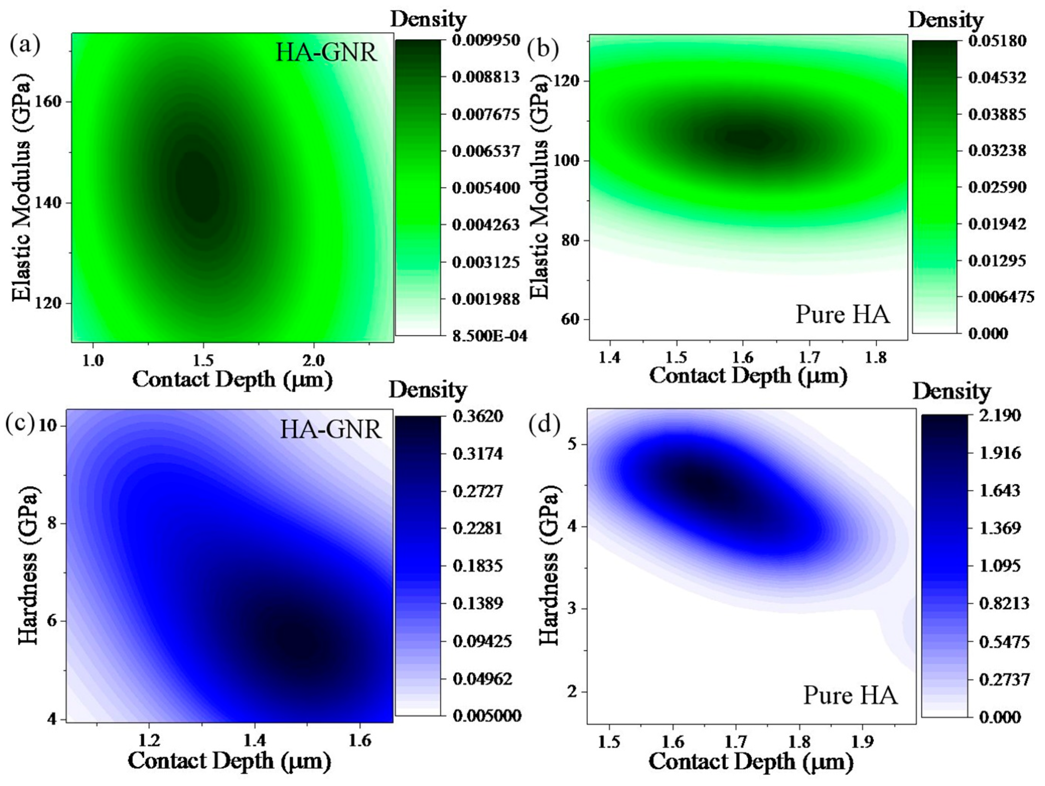
  54. Zhang, B.; Chen, G.; Guo, Q. Static Frame Model Validation with Small Samples Solution Using Improved Kernel Density Estimation and Confidence Level Method. Chin. J. Aeronaut. 2012, 25, 879–886. [Google Scholar] [CrossRef] [Green Version]
  55. O’Brien, T.; Kashinath, K.; Cavanaugh, N.; Collins, W.; O’Brien, J.P. A fast and objective multidimensional kernel density estimation method: FastKDE. Comput. Stat. Data Anal. 2016, 101, 148–160. [Google Scholar] [CrossRef] [Green Version]
  56. Wijesinghe, W.; Mantilaka, M.M.M.G.P.G.; Premalal, E.; Herath, H.; Mahalingam, S.; Edirisinghe, M.; Rajapakse, R. Facile synthesis of both needle-like and spherical hydroxyapatite nanoparticles: Effect of synthetic temperature and calcination on morphology, crystallite size and crystallinity. Mater. Sci. Eng. C 2014, 42, 83–90. [Google Scholar]
  57. Kaygili, O.; Keser, S.; Bulut, N.; Ates, T. Characterization of Mg-containing hydroxyapatites synthesized by combustion method. Phys. B Condens. Matter 2018, 537, 63–67. [Google Scholar] [CrossRef]
  58. Saleh, T.A. The influence of treatment temperature on the acidity of MWCNT oxidized by HNO3 or a mixture of HNO3/H2SO4. Appl. Surface Sci. 2011, 257, 7746–7751. [Google Scholar] [CrossRef]
  59. Saleh, T.A. Nanocomposite of carbon nanotubes/silica nanoparticles and their use for adsorption of Pb(II): From surface properties to sorption mechanism. Desalination Water Treat. 2015, 57, 1–15. [Google Scholar] [CrossRef]
  60. Fadillah, G.; Saleh, T.A.; Wahyuningsih, S.; Putri, E.N.K.; Febrianastuti, S. Electrochemical removal of methylene blue using alginate-modified graphene adsorbents. Chem. Eng. J. 2019, 378, 122140. [Google Scholar] [CrossRef]
  61. Saleh, T.A.; Fadillah, G. Recent trends in the design of chemical sensors based on graphene–metal oxide nanocomposites for the analysis of toxic species and biomolecules. TrAC Trends Anal. Chem. 2019, 120, 115660. [Google Scholar] [CrossRef]
  62. Saleh, T.A. Simultaneous adsorptive desulfurization of diesel fuel over bimetallic nanoparticles loaded on activated carbon. J. Clean. Prod. 2018, 172, 2123–2132. [Google Scholar] [CrossRef]
  63. Nosrati, H.; Sarraf-Mamoory, R.; Dabir, F. Crystallographic study of hydrothermal synthesis of hydroxyapatite nano-rods using Brushite precursors. J. Tissues Mater. 2019, 2, 1–8. [Google Scholar]
  64. Nosrati, H.; Mamoory, R.S.; Le, D.Q.S.; Bünger, C.E. Fabrication of gelatin/hydroxyapatite/3D-graphene scaffolds by a hydrogel 3D-printing method. Mater. Chem. Phys. 2020, 239, 122305. [Google Scholar] [CrossRef]
Figure 1. (a) Load-displacement diagram, (b) load-time diagram, (c) contact depth-time diagram, (d) indentation affected zone, and (e) contact depth profile.
Jnt 01 00002 g001
Figure 2. (a,b) XRD pattern of GNR-HA powders synthesized via solvothermal process for 5 h at 180 °C by injection of hydrogen gas at 10 bar, (c) HA crystal planes, and (d) FESEM images of GNR-HA powders.
Jnt 01 00002 g002
Figure 3. (a) EDS analysis, (be) elemental mapping, (f) FTIR analysis, and (g) Raman spectroscopy for GNR-HA powders synthesized via solvothermal process for 5 h at 180 °C by injection of hydrogen gas at 10 bar.
Jnt 01 00002 g003
Figure 4. (a) HRTEM image of GNR-HA powders synthesized via solvothermal process for 5 h at 180 °C by injection of hydrogen gas at 10 bar; (b) HA nanorods crystal planes; and (ce) fast fourier transform (FFT) and inverse fast fourier transform (IFFT) analysis of A, B, and C areas (HRTEM), respectively.
Jnt 01 00002 g004
Figure 5. (a) Load-contact depth diagram, (b) hardness-contact depth diagram, (c) elastic modulus-contact depth diagram, (d) FESEM image of Vickers affected zone for GNR-HA nanocomposite, and (e) FESEM image of nanostructure and Vickers crack after sintering for GNR-HA and indentation.
Jnt 01 00002 g005
Figure 6. Statistical analysis of (a,b) elastic modulus and (c,d) hardness for GNR-HA nanocomposite and pure HA.
Jnt 01 00002 g006
Figure 7. (a) Results of the MTT assay and (b,c) fluorescent cell culture images on GNR-HA composite after 72 h.
Jnt 01 00002 g007
Table 1. The primary chemical used in the powders synthesis phase.
ChemicalCompanyPurityFormulation
Graphene oxide nanoribbons (GONRs)GONRs were synthesized by chemical unzipping of CNTs under oxidative condition [42]
Calcium nitrate tetrahydrateMerck (Kenilworth, NJ, USA)>99%Ca(NO3)2·4H2O
Diammonium Hydrogenphosphate(NH4)2HPO4
Ammonium solution25%NH4OH
Anhydrous ethanolSigma Aldrich (St. Louis, MO, USA)>99%CH3CH2OH
Dimethyl formamide (DMF)(CH3)2NC(O)H
Dyethylene glycol (DEG)(HOCH2CHc)2O
Table 2. Specification of the hydroxyapatite (HA) scatter planes in graphene nanoribbon (GNR)-HA powders.
2θ (°)(hkl), d-spacing (Å)
26(002), 3.43
32(211), 2.81
32.3(112), 2.77
33(300), 2.71
35.6(202), 2.52
39.9(310), 2.25
49.6(213), 1.84

