
Blockchain-Based Security Model for LoRaWAN Firmware Updates
by
 , and
, and
Njabulo Sakhile Mtetwa
1,*, 
Paul Tarwireyi
1 ,
,
Cecilia Nombuso Sibeko
1,
Adnan Abu-Mahfouz
2 and
Matthew Adigun
1 1
Computer Science Department, University of Zululand, KwaDlangezwa 3887, South Africa
2
Council for Scientific and Industrial Research (CSIR), Pretoria 0001, South Africa
*
Author to whom correspondence should be addressed.
J. Sens. Actuator Netw. 2022, 11(1), 5; https://0-doi-org.brum.beds.ac.uk/10.3390/jsan11010005
Submission received: 13 October 2021
/
Revised: 16 December 2021
/
Accepted: 24 December 2021
/
Published: 7 January 2022
Abstract
:The Internet of Things (IoT) is changing the way consumers, businesses, and governments interact with the physical and cyber worlds. More often than not, IoT devices are designed for specific functional requirements or use cases without paying too much attention to security. Consequently, attackers usually compromise IoT devices with lax security to retrieve sensitive information such as encryption keys, user passwords, and sensitive URLs. Moreover, expanding IoT use cases and the exponential growth in connected smart devices significantly widen the attack surface. Despite efforts to deal with security problems, the security of IoT devices and the privacy of the data they collect and process are still areas of concern in research. Whenever vulnerabilities are discovered, device manufacturers are expected to release patches or new firmware to fix the vulnerabilities. There is a need to prioritize firmware attacks, because they enable the most high-impact threats that go beyond what is possible with traditional attacks. In IoT, delivering and deploying new firmware securely to affected devices remains a challenge. This study aims to develop a security model that employs Blockchain and the InterPlanentary File System (IPFS) to secure firmware transmission over a low data rate, constrained Long-Range Wide Area Network (LoRaWAN). The proposed security model ensures integrity, confidentiality, availability, and authentication and focuses on resource-constrained low-powered devices. To demonstrate the utility and applicability of the proposed model, a proof of concept was implemented and evaluated using low-powered devices. The experimental results show that the proposed model is feasible for constrained and low-powered LoRaWAN devices.
1. Introduction
The Internet of Things (IoT) is a growing system of connected devices with the ability to sense, collect, and transmit data over the internet. It is estimated that the global IoT market will have 24.1 billion devices in 2030 [1]. IoT is fundamentally changing the way business is conducted and is driving a profound transformation in many domains such as agriculture, smart homes, smart cities, public health, and the military and defense industry. To participate in communication networks to send and receive data, IoT devices are usually equipped with either Short-Range or Long-Range communication technologies [2]. While Short-Range communication technologies connect devices over short distances, Long-Range communication technologies have the capability of communicating over long distances. Short-Range technologies include Bluetooth, ZigBee, Infrared, Wi-Fi, and others. Communication between devices is wireless within a smaller-diameter region, for example, Wi-Fi reaches up to 150 feet (46 m). Long-Range technologies connect devices over long distances. Long-Range technologies include LoRa, Sigfox, NB-IoT, and so forth [3]. The aforementioned Long-Range technologies are called Low-Power Wide Area Networks (LPWANs). LPWANs enable devices to consume less power and provide the ability to send data over long distances [4]. Despite bringing about a great transformation that was not possible with most traditional technologies, the issue of privacy and security remains unaddressed. The lack of robust security solutions in IoT is an area of concern to both academia and industry [5].
Due to their ubiquity, vulnerable IoT devices are not only a danger to the networks they connect to, but also to the humans that seek to derive utility from them. In addition to other vulnerabilities, the collateral damage potential can range from none to catastrophic. Looking at the threat and vulnerability landscape, it is clear that the firmware attack surface is evolving into one of the most critical areas of security and needs prioritization [6]. IoT device firmware has become an active part of the attack surface that organizations can no longer afford to ignore. There has been a rise in the number of cases where ransomware and malware have targeted firmware vulnerabilities to cause harm, steal credentials, or even disable critical infrastructure. The Microsoft Security Team conducted a study and released a report in March 2021 [7] that shows how the rise in firmware attacks affects organizations, as per Figure 1.
This study shows that 83% of businesses have experienced a firmware attack in the past two years. Moreover, it should be noted that firmware sits beneath the kernel, therefore controlling the firmware provides opportunities for escalating privileges on the device to the highest level. Consequently, attackers could bypass security mechanisms that run in subsequent layers, such as the operating system, allowing them virtually unfettered access to the device. For example, a study conducted on cyber-attacks on medical implants demonstrated the effects of firmware and communication protocol vulnerabilities on pacemakers [8]. The inability to provide authentication and confidentiality on the remote management channels resulted in successful attacks. It was demonstrated that attackers could control the vulnerable pacemaker to run the battery flat, control the patient’s heartbeat, and modify its behavior. From this example, it is clear that the security of smart devices cannot be ignored, because it can have detrimental effects not only on the affected systems but also on human lives. Therefore, taking due diligence, as far as security is concerned, will go a long way in improving the adoption of such technologies.
LoRa is a robust ISO/OSI Layer 1 wireless technique that can transmit and receive radio waves over long distances and is suitable for applications that transmit small chunks of data with low bit rates [9]. LoRa is also suitable for sensors and actuators that operate in low power mode and at low cost. LoRaWAN is a Media Access Control (MAC) layer protocol built on top of LoRa to tell devices how to use the Lora hardware [10]. Even though LoRaWAN is generally secure by design, the security result depends on how it is implemented. LoRaWAN provides security mainly through symmetric cryptography [11]. The messages sent over the network are encrypted using the Advanced Encryption Standard (AES) for confidentiality and the Message Integrity Code (MIC) for authenticity together with integrity. Despite the built-in security, LoRaWAN is susceptible to security attacks [12]. Just like any security technology that uses encryption, key management and the encryption processes are some of the fundamental challenges, more so with LoRaWAN because of its resource-constrained nature. Hence, there is a need for solutions that enhance security by addressing these problems.
One of the most-used of the technologies that enhance the security of IoT systems is Blockchain technology. Blockchain is an emerging technology that can also be incorporated in LoRaWAN to enhance security. Blockchain is a decentralized peer-to-peer network not managed by a third party [13]. The data stored on the Blockchain is mined or verified by multiple nodes on the network. Blockchain security is based on asymmetric cryptography and hashing, making it immutable and tamper-proof. Moreover, Blockchain consists of the immutable and tamper-proof smart contract which is a logic that enforces the rules of the Blockchain. Recently, some studies incorporated Blockchain to strengthen the security of LoRaWAN. For example, ref. [14] proposed a security model based on Blockchain and asymmetric cryptography to provide non-repudiation in LoRaWAN. The authors in [15] proposed a secure architecture for key management utilizing permissioned Blockchain to enhance security and availability in LoRaWAN. These studies add an extra layer of security to mitigate possible attacks and eliminate vulnerabilities. The additional layers of security are mandatory in the IoT, to ensure that the devices are secured since most are being manufactured and deployed and are expected to stay active on the Internet for an extended period. Vulnerabilities are inevitably going to be discovered when these devices are already operating in the field. Fixing these vulnerabilities will require device manufacturers to release new firmware versions that will mitigate the vulnerability and keep the device up to date. However, coming up with a secure firmware update mechanism for IoT devices is a challenge, especially when it comes to constrained devices. The nature of the IoT makes it hard to deliver firmware updates due to the existence of a large number of devices that are geographically separated and at times deployed in difficult-to-reach areas. This makes it impracticable to provide manual updates since one has to remember all the physical locations of thousands of IoT devices that need to be updated. There is, therefore, a need for automated over-the-air (OTA) ways to convey firmware updates to the thousands of deployed devices.
The traditional client–server-based architecture, which is the de facto firmware update mechanism, is not suitable for IoT, because it exhibits several shortcomings including a single point of failure. Concomitantly, there is a need to explore other ways of conveying firmware updates, especially distributed approaches. This study presents a security model that utilizes Blockchain and InterPlanentary File (IPFS) to secure firmware updates in LoRaWAN. The proposed security model focuses on low-powered devices in LoRaWAN, intending to provide integrity, confidentiality, availability, and authentication during the firmware updates. The main contributions of this study are as follows:
- It presents the design and implementation of a Blockchain-based security model suitable for LoRaWAN using public permissionless Blockchain to secure firmware updates in LoRaWAN.
- The proposed work introduces the Firmware Update Service (FUS) that is responsible for the complete orchestration of firmware updates. The FUS manages the entire firmware update process of low-powered devices, performs the fragmentation, and maintains the end-to-end encryption.
- Finally, this work evaluates the impact of the security measures taken to secure the firmware and the overall cost involved in LoRa transmission.
This paper contains the following sections: Section 2 explains the concepts used in the proposed model; Section 3 outlines the recent studies that focus on the security of firmware updates in constrained networks; Section 4 presents the Blockchain-based security model in detail; Section 5 presents the implementation of the security model and the experiment architecture; Section 6 provides the results and analysis of the proposed security model and compares the proposed model and other firmware update mechanisms; Section 7 provides the application scenario which demonstrates the utility of the proposed model; and, finally, the conclusion and the future work are discussed in Section 8.
2. Background
2.1. Firmware Updates
Firmware updates are necessary in every system, not only in IoT. Attacks against devices stand as some of the highest impact threats facing modern organizations. This shows that firmware attacks are on the rise, and businesses are not paying close enough attention to securing systems.
IT Governance discovered 266 security incidents between July and September 2021, which accounted for 185,721,284 breaches [16]. Figure 2 shows that the healthcare and health sciences sectors accounted for the highest numbers of security incidents followed by the public sector, which was the leading sector with the most security incidents in the previous report. Several companies have been affected by security breaches in June 2021. One example is an incident that occurred with Electronic Arts, which is one of the world’s biggest video game publishers. Attackers broke into the systems and stole the source code for FIFA 21, as well as the code for its matchmaking server [17]. Another breach that occurred involved attackers exposing private information, such as the emails, phone numbers, and addresses of McDonald’s customers and employees located in South Korea and Taiwan [18]. These attacks have highlighted the need for a solid mechanism to secure systems and eliminate vulnerabilities.
2.2. InterPlanentary File System
IPFS is defined as a protocol and a peer-to-peer distributed file system that seeks to connect all computing devices with the same systems of files [19]. Before IPFS, content was only accessed via protocols such as the Hypertext Transfer Protocol (HTTP), where content is accessed based on its location using the address on the server. HTTP is based on the client–server model, and the availability of the content relies on the central authority. If servers are offline, the content cannot be retrieved; whereas IPFS is based on the decentralized peer-to-peer model, where the content is copied and accessed from multiple nodes eliminating a single point of failure. IPFS uses content addressing to identify content instead of using the content’s location. IPFS integrates many of the best ideas from the most successful systems. The InterPlanetary File System is derived from the following technologies:
- Distributed Hash Tables (DHTs): IPFS utilizes distributed hash tables to find which peers are hosting the file. A hash table is a data structure based on the key–value pair. The DHT is distributed and updated across all the peers in the network [18]. The file can be found by asking the peers in the network since they all have the DHT.
- Block Exchanges (Bitswap): The core module that handles the exchange of blocks is the Bitswap protocol. Bitswap is a message-based protocol where all messages contain want-lists or blocks. It handles the requesting and sending of blocks to and from other peers in the network. The Bitswap protocol performs two main operations: it obtains the requested blocks and sends the blocks to other peers in the network [20].
- InterPlanetary Version Control Systems (IPVC): IPVC utilizes the version control system to provide version capabilities. This version control is suitable for large files and any type of content [21].
- Self-Certified Filesystems (SFS): SFS is a distributed file system that does not need any permissions for data exchange. It is a self-certifying filesystem, meaning that when the data is served to a peer, it is authenticated by the unique filename [22]. Each peer on the IPFS network is identified by the node ID that is produced from the node’s public key. It also holds a private key that is stored in the configuration file used for signing data. The peer also has the public key that is used for node identification in a network. During the communication, the public keys are exchanged so that when the peer communicates with other peers it can authenticate them. Authentication is achieved by computing the hash of the public key and matching it against the node ID, and, if the computed hash matches the node ID, the node can be trusted.
IPFS works very well with Blockchain technology. The combination of the two is considered to be a “great marriage” and the future of the peer-to-peer network. This happens because IPFS provides a good solution when it comes to storage, since the Blockchain network has limitations on how much data can be stored on the network. For example, the Bitcoin Blockchain network is limited to only storing data up to 1 MB in a block [23]. The data stored on the IPFS is tamper-proof and cannot be accessed by an illegitimate node, since every node is required to have an identity.
2.3. Blockchain and Smart Contract
Blockchain is defined as a decentralized, distributed ledger that stores the data securely. Blockchain maintains a list of records called blocks. A block consists of more than one transaction where computers verify each transaction using computers with high processing capabilities called miners. Miners validate new transactions and record them on the ledger and earn an amount of money for the validation and verification of transactions. There are a couple of terminologies related to the execution of transactions. These include:
- Gas: A unit of measurement that refers to the computational effort required to execute specific operations. The different kinds of operations will have different amounts of gas.
- Gas limit: Before the transaction is executed, the owner of the transaction is required to specify the maximum number of units of gas they are willing to pay for a transaction to be carried out. This number is called the gas limit.
- Gas used by transaction: This is the actual amount of gas that is used during execution. If the transaction owner specified an excessive amount of gas before the execution, the remaining gas will be returned to the owner.
- Gas price: The transaction owner also needs to specify the gas price before the transaction is carried out. This is the amount the owner is prepared to pay for each unit of gas. This can also be measured as a small fraction (gwei).
- Gas fee/transaction fee: This is the actual amount of fees the transaction owner will pay. It is usually measured in small fractions of the cryptocurrency, Ether (ETH), commonly referred to as gwei. The gas fee is the product of the gas used by the transaction and the gas price.
An example will be used to have a better understanding of how the transaction is executed successfully. The transaction includes the following information:
- Gas price (GP)
- Gas limit (GL)
- Nonce (N), the transaction sequence number for the sending account; this number increases for each transaction made by the sender
- To (AR), this field represents the destination address; it can be the recipient account or the smart contract address
- Data (TD), this field contains the code to execute a transaction in the Ethereum Virtual Machine (EVM), for example, in the case of contract deployment, this field will have the byte code of the contract along with the parameters to call the constructor (if any); this field may also contain the method signature along with the parameters
- Value (TV), this represents the amount of Ether that is transferred between sender and recipient
- {v, r, s}, the signature is represented by 3 variables: v, r, and s
Now, suppose Alice wants to make a transaction to pay Bob 2 amounts of Ether (TV). Alice will have to first specify the amount of gas (e.g., 25,000) she is willing to pay for the transaction (GL) and also provide the price for each unit of gas–gas price (e.g., 200 gwei) (GP). After specifying the gas, Alice signs the transaction and sends it to Bob.
The signing mechanism is based on the Elliptic Curve Digital Signatures Algorithm (ECDSA):
(r, s) = ECDSA_Signing (Keccak256 (N, GP, GL, AR, TD, TV))
The signing algorithm takes the data generated by the sender and produces the Elliptic Curve Digital Signature Algorithm (ECDSA) signature represented by (r, s):
Public key = ECDSA_Verifing (Keccak256 (N, GP, GL, AR, TD, TV)), v, r, s)
The transaction will be validated and verified by miners via the ECDSA_Verifing algorithm which takes the original data produced by the sender and matches it against the signature (r, s) produced during the signing process. If the private key produced is that of the sender, the transaction continues. The transaction will use a certain amount of gas from the provided gas (gas used by the transaction, e.g., 21,000 gas) and, if the provided gas is sufficient, the transaction will execute successfully and the remaining unused gas will be sent back to Alice which is 25,000 − 21,000 = 4000 gas. The total cost for the transaction (gas fee) will be 21,000 ∗ 200 gwei = 4,200,000 gwei, which is equivalent to 0.0042 Ether, and this is the amount the miner will receive. Therefore, Alice pays 2 + 0.0042 = 2.0042 Ether in total.
From the aforementioned example, the transaction is achieved or authenticated via the ECDSA algorithm. Blockchain security is strengthened by the hashing technique, where each block contains the hash of the previous block to enable the immutability of data stored in blocks. Blockchain technology is known for the following key characteristics:
- Decentralization: As mentioned, it is a peer-to-peer platform that does not depend on a single entity or a third party but is controlled by multiple nodes in the network.
- Openness: Blockchain relies on multiple nodes to maintain the ledger. Hence, anyone can join, make transactions, and be part of verifying the transactions.
- Auditability: It is auditable because all transactions can be traced back from the time they were created.
- Persistency: It is impossible to delete or alter the transaction once it has been verified and stored in the block.
Blockchain was initially applied in cryptocurrency; however, in later stages, it was applicable in many areas such as finance, public service, IoT, software-defined networks, and so forth [24]. Blockchain is an independent network and can interact with other networks such as IoT. For it to interact with the outside world, Blockchain needs to expose some interfaces so that external entities can interact with the network. This is usually achieved by the Blockchain feature called the smart contract. The smart contract is a logic that is stored and runs on the Blockchain network, hence it inherits the Blockchain characteristics described above. Blockchain data can be accessed by connecting via the node that is synced with the network. Several nodes can be used for this:
- Ganache–CLI: This is a tool that acts as a Blockchain node, usually used to create a local Blockchain network for testing and local development [25].
- Geth: This is the Blockchain node that can run on the local computer and sync with the private or public Blockchain network [26].
- Infura Node: This node is a service node on the public network and is controlled by a third party that uses an Application Programming Interface (API) to access the node to interact with the network [27].
2.4. IoT Security
To secure the network and end devices, cryptographic techniques are required. Using the existing proven techniques to secure the network and every entity that forms the part of the network is recommended. Due to the resource-constrained nature of the IoT, traditional security techniques are not directly applicable and compatible with IoT devices [28]. The constraints include a shortage of Random-Access Memory (RAM), inadequate flash memory, limited processing power, limited energy power supply, restrictions of communication protocols used by the devices, etc. Some of the IoT devices may use traditional security techniques, but it may become difficult to incorporate them in other devices. Symmetric cryptography and asymmetric cryptography are commonly used to secure devices. Symmetric cryptography is based on a shared secret key between two entities, while asymmetric cryptography uses mathematically linked public and private keys for encryption and decryption.
IoT devices are categorized into three categories: low-end, medium-end, and high-end devices. The Internet Engineering Task Force (IETF) further categorizes the low-end devices into three categories: Class 0, Class 1, and Class 2, as shown in Table 1. Class 0 devices consist of limited memory devices with approximately 10 kB and 100 kB of RAM and flash memory, respectively. These devices have severe constraints to communicating securely over the network, which are, usually, are pre-configured and connected to the internet via gateways or servers. Class 1 devices are less constrained compared with class 0 and can run IoT stacks, such as User Datagram Protocol (UDP), Constrained Application Protocol (CoAP), and lightweight security protocols, such as Datagram Transport Layer Security (DTLS), which are based on symmetric cryptography. Class 2 devices can make use of traditional protocols and perform heavy operations compared to Class 0 and Class 1. Middle-end devices also have constrained resources but are better than low-end IoT devices. This means more features can be incorporated into these devices. For example, more than one communication technology can be incorporated. High-end devices can run traditional operating systems (OS) such as Linux and Windows and perform heavy operations. Moreover, they can incorporate traditional cryptographic techniques, such as asymmetric cryptography without worrying about computing resources.
IoT devices need to be kept updated to ensure their security on the network. Firmware updates need to be executed in a way that ensures authentication, integrity, and confidentiality. It is necessary to prove that the firmware has not been modified both at rest and in transit. Furthermore, it must be proven that it comes from a legitimate source (authentication). The end device needs to perform integrity and authentication before the firmware is installed. Integrity and authenticity can be achieved either using symmetric or asymmetric cryptography. Symmetric cryptography is lightweight and can be incorporated into constrained devices, for example, a LoRa stack uses symmetric cryptography to provide end-to-end encryption between the network server and the IoT devices.
3. Related Work
Even though a firmware update is a critical component of cyber hygiene in IoT, the existing tools, processes, and controls are mostly insufficient to rapidly mitigate the associated risks. As highlighted before, applying firmware updates in constraint networks such as LoRaWAN is a challenge because, besides the resource-constrained nature of the devices, the network data rates are also much lower than the traditional networks. For instance, the LoRaWAN data rate varies from 300 bps to 37.5 kbps, depending on the spreading factor and the bandwidth of the communication channel [28]. Moreover, most of these networks operate in the unlicensed spectrum (ISM band), therefore, the low-powered devices have to respect the duty cycle of transmission, where the device has to wait for the next available opportunity to send the data. The LoRa Alliance put some standards in place to minimize the cost involved when performing firmware updates in LoRaWAN [30]. The standards include firmware fragmentation, clock synchronization, and multicast. The authors of [31] present the requirements and recommendations that firmware update mechanisms should consider when delivering the firmware updates to low-powered devices in LPWANs. The provided requirements and recommendations include sending the firmware to multiple devices at the same time (multicast), sending large binary packets over a lossy network, and verifying the authenticity and integrity of the firmware.
Recently, the authors of [32] used the LoRa Alliance specifications to demonstrate how firmware updates can be applied in LoRaWAN. The Firmware Update Over the Air Simulator (FUOTASim) was implemented and evaluated to demonstrate the effects of the different FUOTA parameters. The study did not consider security in the firmware update process. The authors of [33] demonstrate the firmware update mechanism that targets LoRa end devices. Two communication technologies, LoRa and Wi-Fi, are being used. The mechanism uses Wi-Fi to retrieve the firmware from the servers. The main reason for using Wi-Fi instead of LoRa is the fact that LoRa has limitations. These limitations make it hard to obtain the firmware image quickly to update the devices; therefore, the mechanism switches from LoRa to Wi-Fi to access the firmware image without delay. However, this approach requires that the end device be equipped with Wi-Fi, which other devices may have. Moreover, the mechanism is good for devices that are not battery-powered and otherwise using traditional technologies may consume the battery of the end device.
The authors of [34] proposed the firmware update scheme that targets embedded devices in IoT. The proposed scheme utilizes Blockchain to check the firmware version and the correctness of the firmware image. The proposed scheme treats every IoT device as a node that holds the ledger in the Blockchain network. Most IoT devices have low processing capabilities and not much memory to hold the Blockchain ledger. Therefore, it may be difficult for resource-constrained device to implement. The authors of [35] proposed using Blockchain technology to update the software and firmware of the IoT devices securely. The firmware update solution focused on the resource-constrained IoT. This study only provides integrity verification of the firmware. Therefore, more security is needed beyond integrity, such as determining whether the firmware was coming from a legitimate source, and beyond confidentiality, non-repudiation, and data freshness.
The authors of [36] proposed two techniques that deliver firmware updates. The first technique is a direct firmware update where the IoT devices download the update from the manufacturer’s server through the gateways, and IoT gateways can share the downloaded firmware updates from the manufacturer’s server. IoT gateways load off the work for servers by doing the integrity check and validity of the update for the Blockchain network. The second technique is where the firmware is distributed on peer-to-peer networks. The proposed techniques utilize smart contracts to check the firmware update. The evaluation results show that the peer-to-peer firmware update technique has better time performance than the direct firmware update technique. The provided techniques are good for IoT devices with sufficient resources but not for constrained devices with limited storage. IoT devices need to hold firmware and share the latest updates through IoT gateways. Recently, the authors of [37] proposed a Blockchain-based framework to securely update the firmware of the IoT devices using the LoRa. The work is based on the simulation tool developed by [32] to perform the evaluations. The work is not clear about the cryptographic algorithms used to secure the end device and what kind of devices the proposed framework targets. The authors of [38] proposed a Blockchain-based approach where the IPFS was used to store the software file to achieve the high availability of the software. The proposed mechanism ensures the integrity of the software file and targets the devices with enough resources to carry cryptographic operations. The benefits and the limitations of the related work are summarized in Table 2.
Each aforementioned study covers certain security properties. Some target low-end devices and others high-end devices. In Table 3, some mechanisms take a distributed approach, specifically the Blockchain, while others take the client–server-based model to distribute the firmware. It was observed that most of the proposed Blockchain-based schemes do not focus on constrained networks, such as LoRaWAN which consists of devices that are too constrained in resources, specifically low-end IoT devices. Therefore, this study presents a Blockchain-based security model that suits resource-constrained devices in LoRaWAN.
4. Proposed Security Model
This section describes the proposed security model in detail. Before the proposed model is presented, the security model’s assumptions and requirements are explained, followed by the system architecture demonstrated in Figure 3. The proposed smart contract operations available for firmware are also described in Figure 4, and finally, the security measures taken to secure firmware updates in LoRaWAN are described.
4.1. System Requirements and Assumptions
In this section, we state the requirements for secure firmware updates and the assumptions made in this work. We also provide the reasons for the given assumptions. The following conditions need to be met in order to install a new firmware image securely to the low-powered device. These requirements are based on the studies presented in the literature and are also influenced by the recommendations made in publications such as Cloud Security Alliance (CSA) and other recommendations on performing updates in LPWAN networks [39].
- System design should allow administrators to schedule updates to their devices to avoid network saturation and limit unintended downtime.
- One component must manage updates of multiple microcontrollers that compose IoT devices.
- The firmware update must be designed to be deployed over the air, and the update strategy should be adapted to the bandwidth constraints.
- Updates should be authenticated and integrity protected from end-to-end
- ○
- Authentication: The model should identify the firmware source, e.g., the manufacturer, so that the right firmware is stored on the end device.
- ○
- Integrity: The model should be able to check if the firmware image has not been modified both at rest and in transit.
- ○
- Confidentiality: The process of updating firmware involves sensitive information which may be required to be transmitted between different entities in the process. Hence, the information must only be be seen by the intended entity; therefore, it must be encrypted for confidentiality.
- Availability: End devices must be updated regardless of whether the manufacturer’s repository is off the network. Therefore, the model must eliminate the single point of failure.
- Replay Attack: The sensitive messages such as session keys can be eavesdropped on by the attacker during firmware updates; therefore, the model must make sure that no old messages are sent.
- Low-power consumption: The model must be suitable for low-powered (battery-powered) and constrained devices since most of the devices in LoRaWAN operate on battery and most are low-end devices without many resources.
- Heterogeneous devices: The IoT network consists of devices from different vendors, therefore the model must take into account the hardware heterogeneity of the IoT by not considering a single vendor.
The proposed security model has the following assumptions:
- Encryption and decryption keys are on the secure hardware module.
- The firmware image is stored in public storage where anyone can have access.
- The firmware updates are applied on constrained devices with low processing capabilities and memory limitations.
4.2. System Architecture
The system architecture involves eight entities: low-powered devices, LoRa gateway, LoRaWAN servers (gateway, network, join, application, and identity server), firmware update service (FUS), Blockchain, IPFS, device owner, and the manufacturer. This section explains each component, together with its functionalities and a rationale for the choice.
- Manufacturers: Are responsible for the creation of the new firmware to make sure that the manufactured devices are up to date with the latest specifications, etc. They constantly push the firmware image and metadata to the IPFS and Blockchain network, respectively.
- Low-powered/LoRa devices: Firmware updates need to be delivered to IoT devices, and, since we are dealing with a constrained network, the device equipped with LoRa interface is required. This entity exchanges messages with other devices in the network via the LoRa gateway.
- Device Owners: The low-powered devices need to be configured and managed for firmware updates. The device owners are responsible for that.
- LoRa Gateway: Since the focus is on constrained devices, most cannot connect directly to the Internet to communicate with other devices. Moreover, most are not equipped with the LoRa interface; therefore, the gateway must establish communication among the devices. The gateway is equipped with LoRa and other interfaces that can connect low-powered devices with the outside world. The gateway receives and transmits data from the multiple low-powered devices and sends data to the LoRaWAN servers for further manipulation.
- LoRaWAN servers: The gateway does not process any messages received from the low-powered devices; therefore, there must be a place where messages can be processed. There is a number of LoRaWAN servers available to choose from, but this study considers The Things Network (TTN) stack V3 which is comprised servers that handle LoRa packets. The stack is open source, and it was chosen since it supports all LoRaWAN versions. Different modes of operation (Class A, B, and C) make it easy to manage users, gateways, applications, and end devices. The TTN stack V3 servers include:
- The Identity Server: Stores the applications, registered end devices, gateways, users, organizations, Open Authentication (OAuth) clients, API keys, and collaborators and acts as an OAuth 2.0 server with login and consent screens. Moreover, it provides different ways of integration.
- The Gateway Server: Maintains connections with gateways that support the UDP, Message Queuing Telemetry Transport MQTT, Google Remote Procedure Call gRPC, and Basic Station protocols. It forwards uplink messages to network servers and schedules downlink messages to the end devices via a LoRa gateway.
- The Network Server: Is responsible for keeping the state of all low-powered devices, performing cryptographic MIC checks, detecting replay attacks by performing frame counter checks, maping LoRa packets to the correct application server, and managing usage of LoRa gateways.
- The Application Server: Decrypts the data received from the LoRa end devices and encrypts the data sent to the low-powered device. The received data can be integrated into other IoT platforms via different protocols such as MQTT and HTTP.
- The Join Server: It is connected to the network server and is responsible for storing end device root keys and handling the Over The Air Authentication OTAA process. It also generates session keys and sends them to the network server and application server to enable the secure transmission of LoRaWAN messages.
- Blockchain: This consists of Blockchain nodes that store firmware, sync firmware metadata, and validate firmware update transactions. It also consists of a smart contract that enforces the rules during the firmware update. This work uses the public Blockchain network, because the metadata is usually shared by the manufacturers publicly, usually via the manufacturer’s website, or to the public repository, such as GitHub. In addition, Blockchain will also ensure that the metadata is stored securely and is tamper-proof.
- IPFS: This is a decentralized peer-to-peer network that consists of nodes that store and sync the firmware image. In the same way that the firmware metadata must be stored publicly, the image must also be stored publicly. Once the metadata is added to the IPFS network, it cannot be changed without altering the content identifier (CID), which enables the storage of data that does not need to change. Moreover, IPFS is chosen since it ensures the availability of the firmware.
- FUS: This study introduces the FUS, which is a component that is connected with the application server to manage firmware updates in LoRaWAN. As mentioned, most of the low-powered devices cannot connect directly to the internet, but they connect via the gateway. The FUS component connects the low-powered devices to the Blockchain network and establishes the end-to-end encryption to communicate securely with low-powered devices during the update process. FUS is responsible for the tasks explained in Table 4.
4.3. Smart Contract in the Proposed Security Model
This section discusses the proposed smart contract operations involved during the firmware update process. The FUS is connected to two smart contracts in the Blockchain network: the manufacturer’s smart contract and the FUS smart contract. The FUS smart contract stores the data related to low-powered devices such as the device ID, the device manufacturer’s smart-contract address, the device model, the device current firmware, and the device update status. The manufacturer’s smart contract enables any entity to retrieve information such as metadata and enables entities to check the availability of new firmware. Each smart contract has a set of operations shown in Figure 4. These operations are explained below.
- Deploy: The manufacturer and the FUS owner must first deploy the smart contract to the Blockchain network before any firmware update process can occur. When the smart contract is deployed, this function assigns the manufacturer’s smart contract address or the FUS smart contract address as the smart contract owner on the network. This enables knowing who created and deployed the smart contract on the network in the future.
- Add New Firmware: The manufacturer calls this function to add new metadata to the Blockchain. This is a crucial function and must not be called by anyone other than the manufacturer. Therefore, this function first checks who has called it before accepting the metadata into the Blockchain network.
- Register Device: The FUS calls this method to register a new low-powered device to the Blockchain. This is also a crucial function and must not be called by anyone other than the FUS owner. Therefore, this function first checks who has called it before it accepts the metadata into the Blockchain network.
- Check Update: The FUS calls this function on the manufacturer’s smart contract to check if there is any new firmware update available for the provided device model. If the firmware update is available, it returns true or else false.
- Retrieve Devices by Model: This function retrieves a set of devices by the model’s name.
- Retrieve Device Information: This is a decentralized peer-to-peer network that consists of nodes.
- Retrieve Manifest: This is a decentralized peer-to-peer network that consists of nodes.
- Get Device Status: This function obtains the current state of the device.
The components of the proposed model have been explained, and the proposed Blockchain smart contract operation has been presented. Now, the security model’s specifications are provided. The security of the model is specified by explaining the phases involved during the firmware update process and, from there, by illustrating how security had been achieved in each phase. These phases include the deployment of the manufacturer’s smart contract, firmware distribution, low-powered-device registration, firmware initiation process, firmware download, and firmware distribution to the low-powered device. Each phase is explained in a separate section. The acronyms of the proposed model are presented in Table 5.
4.4. Deployment of the Manufacturer’s Smart-Contract and Update Service Smart Contract
Before any firmware update takes place, the manufacturer’s smart contract and the FUS smart contract must be deployed to the Blockchain network. The deployment stage is where the authorization is enforced. The manufacturer consists of the wallet key or address (KMW) which is the hash of the public key. During the deployment process the wallet address of the smart contract deployer, i.e., the manufacturer is stored on the Blockchain and is later used to control access to the critical operations on the Blockchain network. These operations include distributing firmware metadata to the Blockchain, adding new LoRa end devices, registering a low-powered device, checking firmware updates, and so forth, as shown in Figure 4. The deployment phase results in knowing who the owner of the smart contract is.
4.5. Firmware Distribution
Once these smart contracts are deployed, the manufacturer can distribute the firmware to the Blockchain and IPFS. Figure 5 demonstrates how the model works when the manufacturer distributes the firmware to the Blockchain and IPFS. In this section, we specify the security involved in the deployment:
- Integrity: The firmware image could be modified during transmission. Therefore, the manufacturer hashes the firmware image using the SHA-256 algorithm to prevent any alteration that could take place during the update process. The calculated SHA-256 hash forms part of the metadata.
- Authentication: The manufacturer needs to sign the firmware to prove the ownership digitally. The manufacturer uses the private key to sign the metadata. The ECDSA signature is produced and appended to the firmware metadata. By appending the signature to the metadata, it will be easy to verify the authenticity of the firmware image. Moreover, this enables metadata to be immutable and tamper-proof since it is on the Blockchain network.
- Firmware Availability: The firmware image is deployed on the manufacturer’s IPFS node that syncs with the IPFS network. The other IPFS nodes on the network will sync the uploaded firmware, this ensures the high availability of the firmware image even if the manufacturer’s node is unavailable on the network.
- Authorization: The firmware metadata describes the firmware images. It consists of the integrity hash, the manufacturer’s digital signature, the firmware’s size, firmware version, location of the firmware, etc. Firmware metadata plays a considerable role during the verification process; therefore, not every entity is allowed to deploy the firmware metadata in addition to the manufacturer. The Blockchain smart contract enforces authorization only, allowing the manufacturer to be the only entity on the network to upload firmware metadata.
4.6. Device Registration
The FUS manages the entire update process; therefore, it needs to know about the LoRa-end devices that need to be updated over LoRaWAN. The end device owner provides device details to the FUS, as shown in Figure 6. These details include the manufacturer’s smart contract, manufacturer’s smart-contract address, device model, device ID, etc. The FUS manages the information of these devices through Blockchain and ensures the confidentiality of the data through the Advanced Encryption Standard (AES).
The encryption of the data is conducted utilizing The Counter Mode (CTR) as a mode of operation. Even though the Blockchain provides immutability and is tamper-proof, it is required that FUS encrypts the device’s data before it is stored in the Blockchain. FUS uses the KFUS of 128-bit for both encryption and decryption of the Blockchain data. The device owner has the shared secret key, also known as the master key (KM), of 128 bits that the FUS produces. The KM is used in AES to provide confidentiality of messages between the FUS and the end device. This key should be kept secret between these entities.
4.7. Firmware Initiation Process
In this section, we look at the security involved when initializing the firmware update process. The initialization phase includes the session key exchange and the prevention of the replay attack that could occur during the session key exchange. Figure 7 depicts the session key steps and shows how the replay attack is eliminated. In the case of the low-powered device, the owner can initiate the firmware update, or the firmware update can be automatically started depending on the FUS configuration setting. When the firmware update is initiated by the low-powered device, the idea is to update only a single device instead of a set of devices in this kind of initialization. The owner can perform a push request to update a specific device or a set of devices (multicast), this is completed via the FUS command-line interface (CLI) script which communicates with the FUS. Before the session key exchange occurs, both the low-powered device and the FUS must have shared the secret key in advance. This shared secret key is a KM which was shared earlier in the registration phase explained in the previous phase. After a successful OTAA process, the low-powered devices send the initialization uplink message with a nonce (N) value. The nonce value is randomly generated to prevent replay attacks and must only be used once during the firmware update session. The FUS then generates the Ks which are two keys used to determine the confidentiality, integrity, and authentication of the messages.
It is recommended that the encryption keys be changed over time. Therefore, we generate these session keys instead of using the KM for both encryption and decryption. One of the session keys is the AES session key used to provide confidentiality of sensitive messages such as MIC tags and nonce values. The second key is the MIC session key used for providing the integrity and authentication of the message. The two keys are based on symmetric cryptography. The Hash-based Message Authentication Code (HMAC) provides the integrity, authentication and Cipher-based Message Authentication Code (CMAC) which are MIC algorithms. The nonce value sent by the end devices is received by the FUS which remains known between the two. The FUS then checks for new firmware, and, if the new firmware is available, FUS randomly generates both the AES session key and the MIC session key, updating the nonce value received using a function that increments the nonce and finally generates its nonce value N2.
All these are encrypted using the KM to the end device. The end device decrypts the received data using the shared secret key, KM, then checks if the data has not been replayed by checking the nonce value N1 received. As a response to the session keys, the end device sends the encrypted current version of its firmware image together with the updated N1 and N2. The FUS receives the message and decrypts it to obtain the firmware version of the end device. The firmware update process can be initiated by the end device and by the Blockchain event triggered by the manufacturer by adding new firmware metadata to the Blockchain.
The firmware event initialization may work very well when updating a set on the end device, because it enables FUS to look for all devices that match this new metadata. The session key exchange process is still the same as shown in Figure 7.
4.8. Firmware Download
This phase of the firmware update demonstrates the security measures taken when downloading the firmware image demonstrated in Figure 8. After successfully exchanging the session keys, the FUS requests firmware metadata on the Blockchain network and the firmware image on the IPFS network. The FUS is connected via a secure channel on both the IPFS node and Blockchain node. Firmware authenticity must be achieved. This ensures that the right firmware is sent and updated by the end devices. The following explains the authentication process and integrity verification involved:
- Authentication: In the previous phase of firmware distribution, the manufacturer signed the firmware metadata and uploaded the metadata to the Blockchain network. In this phase, the manufacturer’s digital signature is used to prove the authenticity of the metadata. The manufacturer has three important keys on the Blockchain network: the private key, the public key, and the KMW. As demonstrated, the private key’s job is to sign the firmware and be kept secret. The wallet address is a hashed public key and is allowed to be shared with other entities on the Blockchain network. The wallet address plays a huge role in determining the authenticity of the firmware in the update process. The model uses a function that takes the ECDSA digital signature together with the metadata to produce the wallet address that signed the firmware metadata. The wallet address produced is matched against the wallet address registered earlier in the registration phase by the device owner. If the addresses are the same, this means the metadata comes from the authentic source and can then be used to download the firmware image.
- Integrity: Regardless of the secure channel between the IPFS and the FUS, firmware integrity must be achieved. The FUS obtains the firmware image and recomputes the SHA-256 hash which is then compared with the SHA-256 hash of the metadata. If both hashes are the same, it will be an indication that the firmware image has not been altered during its transmission.
4.9. End Device Firmware Distribution and Verification
After successful firmware verification, the firmware image is ready to be sent over the LoRaWAN. This section describes how the security model secures the firmware image and explains the verification process, as shown in Figure 9, which is performed by the end device. The FUS performs fragmentation based on the spreading factor (SF) and the end device’s region. The MIC of the firmware is first calculated using the HMAC-256/CMAC algorithm and sent over the LoRaWAN, so that the end device can verify both the integrity and the authenticity of the firmware. Usually, the digital signatures based on the public and private keys are used to verify the authenticity and the integrity of the firmware image on the end device; however, since these devices are limited in storage, some cannot incorporate digital signatures, since they require more processing power to complete the verification.
Most of the constrained device’s symmetric cryptography is considered lightweight; even LoRaWAN is based on symmetric-key cryptography to determine the authenticity and integrity of the data. Therefore, the security model adheres to the current cryptographic technique provided by LoRaWAN to deliver firmware updates to the end device via cryptographic technique. Note that asymmetric cryptography is used at the application layer to ensure the firmware’s authenticity and integrity before sending it over LoRa.
- Confidentiality: The MIC needs to be encrypted when sent over the channel; hence, the MIC is encrypted with the session shared secret key KS. The end device receives the MIC and decrypts it with a similar AES session key. The end device uses the CTR mode when decrypting the MIC, as the data was encrypted using the same mode of operation.
- Authentication and Integrity: After the device has received all the firmware fragments including the missing ones, it must determine whether the firmware comes from the authentic source and has not been altered during the transmission. Figure 9 demonstrates this process of verification. Authentication is achieved by recomputing the MIC of the firmware using the HMAC-256/CMAC algorithm. The MIC product is then matched against the one received earlier. If the re-computed MIC and the received one are the same, it proves that the firmware image comes from the right source and has not been altered in transit.
4.10. Activity Diagram
An activity diagram is used to visually present the data flow behind the proposed model as illustrated in Figure 10.
Firstly, the user starts with firmware and metadata as an input into the system, which are deployed on the IPFS network and Blockchain network, respectively. Firmware metadata is validated to ensure it consists of the necessary information required to determine its origin and integrity. The ECDSA and integrity hash are checked, and, once successfully checked, the validated metadata is produced, which is then sent to the Blockchain. The FUS then checks updates or is notified via an event as mentioned in Section 5.4. After a successful update, necessary session keys, signature validation, integrity check, and replay attack checks are performed between the FUS and the low-powered device.
5. Security Model Implementation
This section describes the different hardware and software used in experiments. Figure 11 shows the experiment architecture and the equipment used in the experiments in this work. Table 6 provides the summary of the equipment and the libraries utilized to form the model.
5.1. Computer
A laptop computer running Windows 10 with Ubuntu 20.04.1 LTS as a virtual machine was utilized. Table 7 shows the specifications of the utilized computer.
The computer serves multiple purposes in the proposed model. It runs a decentralized web application (Dapp), shown in Figure 12, that is used by the manufacturers to upload the metadata and firmware image to the Blockchain and IPFS networks, respectively. The Dapp was created using ReactJS, which is the JavaScript library for creating web-user interfaces. The Dapp connects to the public IPFS network via HTTPS with a third-party service node called the Infura node. The firmware image is uploaded to this service node which is then synced with the rest of the peers in the network to ensure the high availability of the firmware image. The connection between the Dapp and the Blockchain is achieved via the Web3js library. The Web3js library requires the provider to connect directly with the Blockchain network. The provider being utilized is MetaMask. MetaMask is injected into the web browser to manage the manufacturer’s Blockchain keys, which are the wallet address, the private key, and the public key. It is also responsible for signing every transaction being made by the manufacturer to the Blockchain.
The Dapp interacts with the manufacturer’s smart contract implemented in the Solidity programming language. The smart contract was first created, compiled, and deployed on the local Blockchain private network. The smart contract functions are demonstrated in Algorithms 1–6. Algorithm 1 shows the algorithm for metadata upload, and Algorithm 2 shows the algorithms responsible for checking firmware availability. Algorithms 3 and 4 are responsible for handling metadata retrieval and low-powered device registration, respectively. The algorithms for obtaining the low-powered device status and obtaining device information are shown in Algorithms 5 and 6.
| Algorithm 1: Upload a new firmware manifest | |
| Input: firmware manifest details Result: manifestList is updated with a new manifest | |
| mapping (string => FirmwareManifest) manifestList; | |
| if msg.sender == firmwareProvider then | |
| Upload the new firmware to the manifestList; | |
| Emit newFirmware (Firmware Details); | |
| else | |
| Error: Not authorized for such operation; | |
| end | |
| Algorithm 2: Check new firmware availability | ||
| Input: model, fv Result: Returns true or false on the firmware availability | ||
| mapping (string => FirmwareManifest) manifestList; String[] public modelList; uint256 i; | ||
| for available model in modelList do | ||
| if model == modelList[i] then | ||
| manifestList[model.version] > fv then | ||
| return true; | ||
| end return false; | ||
| end | ||
| Algorithm 3: Retrieving the firmware metadata | ||
| Input: model Result: Retrieve latest firmware manifest of a model | ||
| mapping (string => FirmwareManifest) manifestList; uint256 i; | ||
| for available model in modelList do | ||
| if model == modelList[i] then | ||
| return corresponding metadata | ||
| end | ||
| end | ||
| Algorithm 4: Register a new LoRa device | |
| Input: device details Result: Updated device list record | |
| mapping (string => string[]) devs; mapping (string => Devices[]) devicesList; string[] public deviceIDList | |
| if msg.sender == updateServiceOwner then | |
| for available device in deviceIDList do | |
| if devID == deviceIDList[i] then | |
| exist == true; | |
| end | |
| end | |
| if not exist then | |
| add a new device to the deviceList | |
| end | |
| else | |
| Error: Not authorized for such operation; | |
| end | |
| Algorithm 5: Get device update status | |
| Input: deviceID Result: Returns device update status mapping (string => Devices[]) devicesList; | |
| functiongetDevStatus(string devID)do | |
| return devicesList[deviceID].status; | |
| end | |
| Algorithm 6: Retrieving the LoRa device information | ||
| Input: devID Result: Retrieve latest firmware manifest of a model | ||
| mapping (string => Devices[]) devicesList; string[] public deviceIDList; uint256 i; | ||
| for available model in modelList do | ||
| if devID == deviceIDList[i] then | ||
| return devicesList[devID].version, devicesList[devID].name, devicesList[devID].model, devicesList[devID].ipfsHash, devicesList[devID].integrityHash, devicesList[devID].signature | ||
| end | ||
| end | ||
These algorithms were tested, compiled, and built locally using Ganache-CLI and Truffle. Ganache-CLI acts as a local Blockchain node that holds a Blockchain ledger and the smart contract. This tool is useful for development purposes; it consists of the fake Blockchain addresses and accounts with fake ether for testing and interacting with the Blockchain network. Truffle is responsible for compiling and producing the smart contract’s build version and deploying it on the Blockchain network, i.e., the local Ganache network, a local Blockchain network. After the smart contract is successfully tested locally, it is then deployed to the public network using Truffle. The proposed model utilizes the public Ethereum Blockchain, since the nature of firmware updates is meant to be shared publicly. However, the smart contract is not deployed on the main network, instead, it is deployed on the Ethereum test network called Rinkeby. The Rinkeby network is an Ethereum test network, which is similar to the Ethereum main network. The Ethereum main network uses real Ether to make transactions, while the Rinkeby test network does not. To connect to the public Blockchain network, the node that is synced with the network is required. In this experiment, the Infura node was utilized.
5.2. LoRaWAN Server and the FUS
The second purpose of the computer is to run the LoRaWAN server. The proposed study utilizes TTN Stack version 3.12.3 as network servers that process LoRa packets. There are alternatives to the TTN Stack, which can be chosen as network servers that handle LoRa packets. One of these alternatives is Helium. Helium is considered to be a network that connects IoT devices. This network is made possible by the device called Hotspot which supports LoRaWAN protocol and is capable of mining the Blockchain. In other words, it connects to the low-powered devices in a decentralized manner and at the same time connects them to the public Helium Blockchain network. Most of these alternatives do not have built-in features that support OTA firmware updates.
The TTN stack on the proposed model supports all the LoRaWAN frequencies, making it possible to connect and update most of the low-powered devices that support LoRaWAN frequencies. Helium is supported for US frequencies, and, therefore, it may not be possible to incorporate devices with different frequencies to receive firmware updates. The TTN stack implements the LoRa standards, such as multicast session, which can be significant in firmware updates, since they enable the sending of a single downlink message to the set of low-powered devices. For these reasons, the proposed model focuses on LoRaWAN servers that support the aforementioned features, and it is useful for network servers that do not directly incorporate Blockchain; hence, the FUS would be added to make that connection possible, but only to update the low-powered devices. The networks such as Helium, as mentioned, provide their Blockchain. It is possible to incorporate the FUS of the proposed model with Helium; however, it will be considered as a duplicate, since Helium consists of its Blockchain, but it can have a benefit for connecting Helium to the Ethereum network.
A computer is also responsible for running the FUS. The FUS is implemented in python and works together with the TTN stack application server. The FUS uses Web3py and IPFS python library (IPFS-API) to connect to the Blockchain and IPFS networks. The FUS communicates over both HTTPS and WebSocket to receive new firmware in real-time. The real-time events are made possible by a running daemon that constantly listens for the events in Blockchain. Figure 13 shows the smart contract event method that the FUS daemon listens to to receive newly uploaded firmware metadata. This event is triggered by the transaction made via the call of the upload Metadata contract method.
The FUS connects over MQTT to send the firmware update LoRa packets using the paho python MQTT library. Figure 14 shows the code snippet of how the FUS script can be utilized by the owner to apply push updates. The owner manages the devices and initiates the firmware update process utilizing the python script that communicates with the FUS via MQTT topic “devices/req” as shown in the code snippet in Figure 14.
5.3. RAK831 Concentrator Module and Raspberry Pi
The proposed model uses the RAK831 concentrator module and Raspberry Pi 3 Model B to form a gateway as depicted in Figure 15 and Figure 16.
The RAK831 concentrator module enables robust communication between the gateway and a number of low-powered devices spread over a wide area. It has the multi-channel (8 channels) capabilities to receive data on different frequency channels at the same time and performs demodulation of the signal without the knowledge of the low-powered used data rate. The data received from the concentrator is forwarded to the LoRaWAN servers for processing. The concentrator has no processing abilities, but it works together with Raspberry Pi to provide the data processing. For example, the LoRaWAN server can be installed in a gateway to handle data packets being sent by the low-powered device.
This transmission of data packets is made possible by the packet forwarder, which is a program that runs on the gateway and enables it to send and receive packets. The installed packet forwarder can be found in the public repository [40].
5.4. LoPy4 and the Expansion Board
The Pycom Expansion Board is a development board which acts as a shield for the Lopy4 model. The Expansion Board provides extra hardware features for the different modules connected to it. These features include powering the LoPy through a USB port, providing serial communication, and containing microSD card additional storage. Figure 17B shows the Pycom Expansion. During the experiment, the LoPy was not powered via the USB port but was battery-powered via the LiPo battery connector. The LoPy4 provided different connection methods including Bluetooth, Wi-Fi, Sigfox, and LoRa. During the firmware update process, the LoPy was only connected via LoRa, whereas other interfaces were inactive. The LoPy devices were equipped with an Espressif ESP32 chipset and a Semtech LoRa transceiver SX1276. During the firmware update, the two LoPy devices were configured to operate in Class A and Class C mode, in the European region, and the LoRa channels were randomly selected.
The datasheets of the LoPy and the Expansion Board can be access via the URL provided in Table 8 which also provides the datasheets of the aforementioned devices which are Raspberry Pi 3 Model B and RAK831 module.
Table 9 shows the experimental parameters used in the evaluation:
- Class Mode: The aim is to test the proposed model when the devices operate in Class A mode, where the device needs to send the uplink message before it receives the firmware fragment. The low-powered device is also equipped to operate in Class C mode, where it is always opened to receive firmware fragments.
- RX1, RX2, and RX delay: The low-powered device receives the fragments in two windows, the RX1 and RX2. The RX2 window/channel has a 10% duty cycle limit, whereas the other channels have a 1% duty cycle limit (per sub-band).
- Gateway and low-powered devices: Only one gateway and two low-powered devices are utilized. The gateway and device respect the duty cycle parameter.
- Region and Bandwidth: The low-powered devices are equipped to operate in the European region, this modulation operates in the radio band 863–870 MHz, with a bandwidth of 125 kHz.
- SFs: The SF impacts the communication performance of LoRa. LoRa utilizes an SF between 7 and 12. The model will be tested with all spreading factors to see the impact of different SFs during the firmware update process.
6. Results and Discussion
In this section, the Blockchain operation costs involved during the update process are examined. In Section 6.2 the cost of updating low-powered devices in the LoRaWAN network and Cryptographic Techniques is analyzed. Section 6.3 shows the comparison between the proposed model and other firmware update mechanisms and explains how the properties provided in Table 3 are fulfilled.
6.1. Evaluating Blockchain Operation Costs and Algorithm Complexity
The Blockchain evaluation results are presented in terms of the following metrics:
- Gas Used which indicates the actual amount of gas used by a transaction. In this case, this the actual amount of gas used by a smart contract operation.
- Gas fee, which indicates the total amount of Ether charged during the transaction of an operation.
The Blockchain cost of the involved proposed operations for the proposed model will first be examined, followed by the costs of the firmware update in the constrained LoRaWAN network, and finally the effect of cryptographic operation used in the update process. In addition to the aforementioned metrics, the impact of different firmware sizes in combination with the aforementioned metrics is measured. The firmware sizes used are 1 kB, 2 kB, 3 kB, 4 kB, and 5 kB. Table 10 and Figure 18 depict some of the FUSs, the manufacturer’s smart-contract operations, and the gas costs involved when these operations are executed in the Blockchain network. Firmware metadata size may vary from time to time. Table 10 shows that gas costs also increase as the firmware metadata increases from 1 kB to 5 kB. Figure 18 also demonstrates that, when adding more metadata, the gas cost increases. Adding the new firmware metadata is considered a transaction on the Blockchain network; the gas limit must be provided, which must be enough to cover a successful transaction.
The increasing relationship between firmware metadata and gas consumption/fees is caused by the fact that, when adding more data to the Blockchain, the fee required to execute the transaction is directly proportional to the amount of data being added. Hence, operations such as registering the low-powered device, adding new firmware metadata, and updating the device information may require more fees when providing more data on these operations. Operations such as obtaining firmware metadata, obtaining device information, and obtaining device information using a model may require no gas since they do not involve transactions. The gas consumption may vary from time to time depending on the cost of gas at that particular moment on the Blockchain network.
The operations or algorithm complexity for the algorithms presented in Section 5 can be measured using the Big-O Notation method. The complexity of the algorithms using the Big-O Notation method is presented in Table 11 below.
Algorithm 1 is responsible for uploading metadata to the network and it takes manifest or metadata as an input. The algorithm performs a comparison operation which is a constant operation taking O (1). If the comparison passes, then the metadata is inserted into a mapping structure. Mapping is essentially a kind of hash table where values are mapped to keys. Since the metadata is being inserted into the mapping, the operation will show a constant O (1). The last part will be to emit the event, which is a constant operation resulting in the time complexity of T(N) = 1 + 1 + 1 = 3. Hence, the total complexity is constantly at O (1). For checking firmware availability in Algorithm 2, the algorithm first checks if the model is in the model list using the for-loop which executes N times, together with the operation inside its body. Therefore T(N) = N (for-loop) + 2N (2 times N comparison inside the loop) = 3N = N; hence, the order of growth is O (N). The order of growth for Algorithms 3, 4, and 6 is affected by the for-loop which takes N steps O (N). Algorithm 5 consists of the instruction that retrieves the device status from the mapping, which makes the order of growth O (1).
The efficient way of measuring the complexity of the algorithms is through the gas. The gas price affects the execution time of the operation. Lowering the amount of gas price paid will lower the total cost of a given operation, it will also ensure that it takes longer. Paying a higher gas price will ensure a transaction is prioritized in the Blockchain, while, in most cases, paying a lower gas price will essentially ensure that a transaction will not take place for at least a few minutes. Higher gas prices generally mean that transactions will be completed faster, while lower gas prices mean they will take more time. The gas costs are shown in Table 10.
6.2. Evaluating the Cost of the LoRaWAN Updates and Cryptographic Techniques
We evaluated the model’s performance using a low-powered device operating in Class A mode and Class C mode. The evaluation results are presented in terms of the following metrics:
- Update Time which is the time taken from when the firmware update is initiated until the firmware image is verified.
- Energy Consumption, which indicates the energy consumed by the low-powered device, the gateway, and cryptography techniques used for signature verification.
- Memory Consumption, which indicates the memory usage of cryptography techniques.
Figure 19 demonstrates the relationship among airtime, firmware size, fragment size, and SF. It shows that sending fragments at a higher SF increases the airtime of the firmware fragment. Increasing the SF by one step, e.g., from SF11 to SF12, doubles the airtime, which is demonstrated in Figure 19B.
Figure 19 also shows that the lower the SF, the lower the airtime even for the same fragment size. For example, the fragment sizes at SF11 and SF12 are the same, but the airtime at SF12 is different from the airtime at SF11. Figure 19A shows that the number of fragments produced depends on the SF. Higher SF values produce a greater number of fragments, e.g., if sending 5 kB of firmware with SF12, the number of fragments is 108, whereas with SF7, the fragments produced are 24. This is due to the regional restrictions of LoRaWAN. Since the end devices operate in the European region, a maximum number of payloads must not be exceeded. For instance, when the end device is operates with SF12, SF11, and SF10, the fragment size must be less than 51 bytes. For SF9 the fragment size must not exceed 115 bytes, and for SF8 and SF7 the fragment size must be less than 222 bytes for efficient transmission. Figure 19B depicts the chosen number of fragment sizes for each spreading factor corresponding to the EU region.
Looking at the time it takes to update low-powered devices, Figure 20 and Figure 21A show the updated time, which starts from when the firmware update is initiated until the firmware image is verified. The two modes of low-powered devices examined were Class A and Class C. The update time, firmware size, and the SF show a directly proportional relationship. For example, updating which operates in the Class A mode with 4 kB of firmware at SF11 takes more time, i.e., 796.10 s (13 min), compared with updating the firmware at SF7, which takes only 108.65 s (1.8 min). There are several reasons which could cause the increase in update time. These could be the firmware size and fragment size. The firmware size has a great impact on update time, because it needs to be fragmented. The greater firmware size means many fragments are required to be produced and, therefore, more fragments are required to be sent to the end device. It could also be affected by the SF and airtime; increasing the SF increases the update time. This is mainly due to the large number of fragments that are being produced at higher SFs. This will result in a long airtime. One of the LoRaWAN restrictions is the duty cycle, which also impacts the update time. LoRaWAN limits the maximum application payload that needs to be sent over the channel. This increase in update time occurs, because each SF LoRaWAN restricts the payload size, resulting in higher SFs sending more fragments to lower SFs.
Comparing the update time of the different modes, which includes Class A, Class C, and multicast, it can be observed that when the devices are operating in the Class A mode, a longer amount of time is needed to update the devices compared to other modes. In Class A mode, the end device needs to send some data before it receives any firmware fragments. Moreover, the network servers set the recommended RX1 delay at 5 s for Class A. This means the next firmware fragment will be received after 5 s. The multicast mode is quite similar to Class C, the difference being in sending the single firmware to the set of devices. The update time figures show that the update time for both Class C and multicast is the same in some cases. For example, when updating the end device at SF8, the update time is the same for all firmware sizes, for both multicast and Class C, but this does not hold in some cases.
Update time is not predictable. This is observed in Figure 22, where the device was updated with 3 kB of firmware operating in Class A mode. It was expected that the SF11 update time should be less compared to SF12, however, that was not the case. This occurred due to the fact that there was a time when the end device was inactive, i.e., not receiving the fragment for some time. This was due to the LoRaWAN restriction of duty cycle. The device had exceeded its duty cycle, which affected the update time. If the time taken to deliver the firmware image matters most, it is preferable to use the lowest SF, i.e., SF7. During the firmware update, it was observed that there were also more firmware fragments lost when the LoPy was operating on the SF7. The higher SF has the benefit of extended airtime. It provides better sensitivity or better coverage for low-powered devices that are further away, in terms of receiving the firmware fragments; however, this causes some delays in the end device update time.
The total number of exchanged firmware fragments is not fixed, it depends on the SF or the data rate used by the low-powered device, the mode the device is operating in, and the retransmitted packets during the update process. For example, Table 12 shows the number of messages exchanged when updating 1 kB of the firmware with SF12. These were the number of exchanged messages during the firmware session.
When the device operates in Class A mode, a greater number of messages will be exchanged compared with the number of messages exchanged when the device is in Class C mode. In Class A mode, the device will always send an uplink message to receive the firmware fragment, whereas Class C mode requires no uplink message to receive the firmware fragment. However, for Class C downlink scheduling to start, there must be an uplink message (activation message) that needs to be sent by the device, particularly after the OTAA join–accept. The number of uplinks comprises activation messages (only if the device is in Class C mode, the activation message is sent twice by the low-powered device to ensure the activation of downlink scheduling), uplink messages for requesting retransmission of missing packets (in this case there was no query of missing packets, the device successfully received packets), the ACK messages for the session keys, metadata, and the update status message exchange that indicates a successful update status after the verification of the firmware. Note that, for Class A, the number of uplink messages generated may be more while the FUS is processing firmware updates, e.g., downloading firmware, metadata, etc. The number of downlink messages comprises the session key exchange, metadata exchanges, 22 firmware fragments, and the last message designating that all firmware fragments have been sent. The 22 fragments were sent because the device was operating with SF12, and Figure 18B shows that each fragment is 46 bytes, therefore, the FUS had to read the 1 kB firmware 22 times.
The costs of cryptographic operations on low-powered devices are important to examine, since the devices are resource-constrained. Both end devices have a built-in RAM of 4 MB and a flash memory of 8 MB, as shown in Figure 23A and Figure 24, which depict both RAM and flash memory consumption when updating 5 kB of the firmware. Figure 23A,B show signature verification time and energy consumption of both MAC algorithms, respectively. The total flash usage when updating the end device with a 5 kB firmware size is 96.7 kB. This is made up of firmware code, firmware size, and the amount of flash memory utilized during the signature verification. The RAM consumption on the end device varies depending on the firmware size and the algorithm used for signature verification. The results show that the CMAC consumes more RAM than the HMAC-SHA256 and also does not verify faster than the HMAC-SHA256, this is because hash functions are usually faster than block ciphers. The reason the CMAC is slower than the HMAC-SHA256 could be the AES mode of operation used, which was MODE_ECB. The CMAC’s total RAM consumption is 7.3 kB, while HMAC-SHA256 consumes 6.9 kB. The RAM and flash consumption results show that these cryptographic techniques can work perfectly in low-powered devices, since most belong to Class 0, Class 1, and Class 2, and CMAC’s RAM and flash consumptions do not exceed these classes. It is also important to measure the energy consumption of these cryptographic techniques to know how much energy is consumed, since most are battery-powered. The power is obtained by measuring the voltage and the current as shown in Figure 11 using multimeters.
It is also important to examine the energy consumed by the low-powered device and the gateway during the update process. Figure 23A depicts energy consumption when the low-powered device was operating in Class A and Class C mode (note that the multicast is similar to Class C, hence, only the energy consumption of Class C was examined). The energy consumption was compared with different SFs from 7 to 12. When the different SFs were compared, Figure 25A shows that SF7 had the lowest energy consumption and SF12 had the highest. Energy consumption continues to increase from SF7 for every SF until SF12. One of the factors that causes the increase in energy consumption is airtime, as demonstrated in Figure 19C. Figure 19C demonstrates that when increasing the SF, a transmission will need more airtime, hence, there is more energy being consumed by the low-powered device.
In addition, calculations were completed to compare the energy consumption between the classes when operating in Class A and Class C, as well as the energy consumption of the gateway. We compared low-powered devices operating in Class A and Class C with fixed payload sizes of 1 kB and spreading factors. Figure 25 shows that Class C mode consumes more energy compared to Class A mode. The figure also shows that the gateway consumes more energy compared to the power of the low-powered device. The benefit of a high SF is that extended transmission provides the receiver more opportunities to sample the signal power, resulting in better coverage; however, the energy consumption is too high compared to other lower SFs.
The HMAC consumes less energy compared to the CMAC algorithm. It can be observed that the increase in firmware size is directly proportional to verification time, memory consumption, and energy consumption. It is then recommended to apply delta updates in these devices rather than larger firmware images, which may result in reduced memory and power consumption and a lower amount of time taken to update.
6.3. Discussion about Properties of the Proposed Model
This section compares the proposed model and the state-of-the-art firmware updates mechanisms shown in Table 13. This section explains how the proposed model fulfilled each property.
6.3.1. Confidentiality, Integrity, and Authentication
The proposed model provides confidentiality of data through AES encryption. The mode of operation for encryption or decryption is MODE_CTR. The FUS encrypts low-powered device data before it is pushed to the network and performs decryption when it retrieves data on the Blockchain network. The end device also performs encryption and decryption of sensitive information such as session keys. Integrity and authentication are provided using the MAC, SHA256, and ECDSA algorithms at different levels. After the firmware is downloaded, the FUS performs firmware integrity and authentication checks before the firmware is sent to the end device. The end device also provides integrity and authentication checks through the MAC algorithm.
6.3.2. Data Freshness
Data freshness is required through confidentiality, and data integrity was provided. Data freshness ensures that data is new, and a man-in-the-middle attack has replayed no old messages. The data freshness in the proposed model is ensured between the FUS and the end device. Both the FUS and the end device have a function that keeps track of a nonce value that is only known between them. For example, when the end device receives the session key, it will verify the nonce value carried on that message against the expected nonce value. If the nonce value is the right one, it will accept the message as new and it know that it was not replayed.
6.3.3. Availability and Peer-to-Peer Network
The proposed model utilized IPFS and Blockchain nodes to ensure a high availability of data. Instead of storing the firmware image on a centralized server, the firmware image is published on the decentralized peer-to-peer IPFS network and syncs with all nodes available in the network. The model utilizes an Infura node to store and retrieve the firmware image stored on the IPFS network. Even if one of the nodes is offline, the firmware will still be downloaded. The firmware metadata is stored on the Ethereum Blockchain network, which ensures the high availability of firmware metadata. The model uses an Infura node connected to the Ethereum network to store and retrieve firmware metadata.
6.3.4. Constrained-Networks, Low-End Devices, and Performance Evaluation
The proposed model was tested and evaluated in a constrained network. The LoRaWAN network was utilized as a constrained network to provide long-range, low power, at a low bandwidth between 250 bit/s and 11 kBit/s in Europe using LoRa modulation (depending on the spreading factor). The proposed mechanism uses low-powered devices as a low end. Blockchain operations, LoRaWAN, and cryptographic costs have been evaluated and analyzed in Section 6.1 and Section 6.2.
7. Application Scenario Utilizing the Proposed Model
This section presents the scenario that helps to understand the proposed model. The application scenario is presented by the low-powered device owner (Alice), the device manufacturer (DM), and the attacker (Bob). Suppose Alice has a garden planted in a rural area that is far from her home. She bought a LoRa-end device with a LoRa gateway. The device is equipped with Wi-Fi and LoRa. She plans to use the end device to monitor the soil moisture so that she can make decisions about what to do about plants based on the data she receives from the low-powered device. Since the garden is far from her home and in a place where there is no electricity, she cannot connect the device via Wi-Fi. Alice also wants to keep the low-powered device safe from people such as Bob who may try to obtain access to the end device to produce fake data that might be misleading to Alice and result in her not growing the plants accordingly. Alice downloads the FUS from the DM website and runs it on her computer. The downloaded FUS will help her convey the firmware safely to the end device.
It is assumed that the DM has deployed the smart contract to the public Blockchain network and holds three Blockchain keys: the private key, the public key, and the wallet address. The DM has a ready smart contract to store firmware data, and Alice has configured the FUS to securely serve firmware updates to the end device. Now, suppose the DM announces a bug that can lead Bob to access Alice’s device to produce fake data. Before the DM releases a new firmware update, Bob tries to impersonate the DM to produce the fake firmware. Bob may know the DM smart contract address on the Blockchain network, the smart contract logic that was deployed on the Blockchain, and finally, the public key and the wallet address of the DM, but not the private key of the DM. So, he tries to upload the new firmware to the Blockchain knowing that the FUS will serve the malicious firmware to Alice’s device. Unfortunately, Bob cannot upload and transmit the firmware to the end device because he does not have the DM’s private key, since the smart contract logic restricts who may upload new firmware to the Blockchain network.
Suppose now, the DM uploads the new firmware to the Blockchain, and Alice has already configured the FUS to receive the updates. The FUS establishes the session keys and pushes them to Alice’s device. However, Bob eavesdrops on the session keys and tries to use them later. In the future, Bob waits for Alice’s device to initiate firmware updates and reply with earlier session keys captured during the previous update. However, Alice’s device prevents this kind of replay attack, since the unique randomly generated nonce is only known between the FUS and Alice’s device; therefore, this makes it impossible for Alice’s device to use session keys provided by Bob. After Bob fails to establish a session with Alice’s device, he somehow pushes a fake firmware fragment to Alice’s device. When Alice’s device has received all fragments, it verifies them and, since one of them comes from Bob, the verification process will capture that and not install the firmware. Note, Alice’s device is safe from the attackers and can be updated in an environment where there is no electricity, with no need for Wi-Fi, and finally, Alice’s device information is stored safely in an immutable manner.
8. Conclusions
Privacy and security in the IoT are still a challenge. Most of the bugs and vulnerabilities are found while these devices are in the field, therefore, it is required that security measures are taken to mitigate the vulnerabilities. In this study, we proposed and implemented a Blockchain-based security model that could be used to enhance LoRaWAN security during the firmware update process. We evaluated a proposed model showing the impact of updating LoRa Class A, Class C, and multicast devices. The results showed that firmware size in the constrained networks has a great impact on update time. For example, updating a low-powered device with 4 kB of firmware at SF7 can take 108 s (1.8 min), whereas, at SF12, can take 796.10 s (13 min); this could be even longer for a larger firmware size. Firmware size also greatly impacted the verification process, i.e., using either of the MAC algorithms (HMAC-SHA256 and CMAC) will require more RAM when the firmware image becomes larger. This implies that the model can work for constrained devices, but also that it depends on the firmware image size which plays a huge role in the verification process. The model is designed and implemented to handle the scalability of firmware update requests. Unfortunately, larger-scale tests were not possible, due to the limited number of end devices. In future work, we plan to improve the proposed model by incorporating asymmetric cryptography and examining the effect of the Blockchain-based ECDSA algorithm.
Author Contributions
All the authors contributed to the work and wrote the article. N.S.M.: proposed the idea and assisted with designs, implementation, and writing. P.T.: assisted with supervision and suggested directions for the detailed designs as well as coordinated the work. C.N.S., A.A.-M.: supervision and writing. M.A.: project administration and funding acquisition. All authors have read and agreed to the published version of the manuscript.
Funding
Funded by the Council for Scientific and Industrial Research through the SmartNetworks collaboration initiative and IoT-FactoryProgram (Funded by the Department of Science and Innovation—Contract number: DST/CON 0220/2019). The authors acknowledge the contributions of the following sponsors in making this research possible: Centre for Scientific and Industrial Research, The Department of Science and innovation, Telkom SA Ltd, and University of Zululand.
Institutional Review Board Statement
Not applicable.
Informed Consent Statement
Not applicable.
Data Availability Statement
Any data will be available upon request to the corresponding author.
Acknowledgments
This research was supported by the Council for Scientific and Industrial Research, Pretoria, South Africa, through the Smart Networks collaboration initiative and the IoT-Factory Program (Funded by the Department of Science and Innovation (DSI), South Africa).
Conflicts of Interest
The authors declare that they have no conflict of interest regarding the present study.
References
- IoT Connected Devices Worldwide 2019–2030 Statista. Available online: https://0-www-statista-com.brum.beds.ac.uk/statistics/1183457/iot-connected-devices-worldwide/ (accessed on 12 October 2021).
- Leverege LCC. An Introduction to the Internet of Things; Leverege LCC: Washington DC, USA, 2018. [Google Scholar]
- Foubert, B.; Mitton, N. Long-Range Wireless Radio Technologies: A Survey. Futur. Internet 2020, 12, 13. [Google Scholar] [CrossRef] [Green Version]
- LinkLabs. Low Power, Wide Area Networks Networks (LPWANs). Thales 2017, 19, 855–873. [Google Scholar]
- Tawalbeh, L.; Muheidat, F.; Tawalbeh, M.; Quwaider, M. Applied Sciences IoT Privacy and Security: Challenges and Solutions. Appl. Sci. 2020, 10, 4102. [Google Scholar] [CrossRef]
- Microsoft Digital Defense Report. Netw. Secur. 2020, 2020, 4. [CrossRef]
- New Security Signals Study Shows Firmware Attacks on the Rise; Here’s How Microsoft is Working to Help Eliminate This Entire Class of Threats. Available online: https://www.microsoft.com/security/blog/2021/03/30/new-security-signals-study-shows-firmware-attacks-on-the-rise-heres-how-microsoft-is-working-to-help-eliminate-this-entire-class-of-threats/ (accessed on 12 October 2021).
- Rehman, M.M.U.; Rehman, H.Z.U.; Khan, Z.H. Cyber-Attacks on Medical Implants: A Case Study of Cardiac Pacemaker Vulnerability. Int. J. Comput. Digit. Syst. 2020, 9, 1229–1235. [Google Scholar] [CrossRef]
- What are LoRa and LoRaWAN?|The Things Network. Available online: https://www.thethingsnetwork.org/docs/lorawan/what-is-lorawan/ (accessed on 12 October 2021).
- Ertürk, M.A.; Aydın, M.A.; Büyükakkaşlar, M.T.; Evirgen, H. A Survey on LoRaWAN Architecture, Protocol and Technologies. Futur. Internet 2019, 11, 216. [Google Scholar] [CrossRef] [Green Version]
- Brtnik, V. Security Risk Assessment of LoRaWAN. Master’s Thesis, Leiden University, Leiden, The Netherlands, 2018. [Google Scholar]
- Aras, E.; Ramachandran, G.S.; Lawrence, P.; Hughes, D. Exploring the Security Vulnerabilities of LoRa. In Proceedings of the 2017 3rd IEEE International Conference on Cybernetics (CYBCONF), Exeter, UK, 21–23 June 2017. [Google Scholar] [CrossRef] [Green Version]
- Atzori, M. Blockchain Technology and Decentralized Governance: Is the State Still Necessary? J. Gov. Regul. 2017, 6, 45–62. [Google Scholar] [CrossRef]
- Durand, A.; Gremaud, P.; Pasquier, J. Decentralized LPWAN Infrastructure Using Blockchain and Digital Signatures. Concurr. Comput. 2020, 32, e5352. [Google Scholar] [CrossRef]
- Ribeiro, V.; Holanda, R.; Ramos, A.; Rodrigues, J.J.P.C. Enhancing Key Management in Lorawan with Permissioned Blockchain. Sensors 2020, 20, 3068. [Google Scholar] [CrossRef] [PubMed]
- Data Breaches and Cyber Attacks Quarterly Review: Q3 2021-IT Governance UK Blog. Available online: https://www.itgovernance.co.uk/blog/data-breaches-and-cyber-attacks-quarterly-review-q3-2021 (accessed on 12 October 2021).
- The Stolen Source Code For FIFA 21 Was Just Published Online. Available online: https://www.pandasecurity.com/en/mediacenter/security/source-code-fifa-21/ (accessed on 12 October 2021).
- McDonald’s Hit by Data Breach in Taiwan and South Korea-BBC News. Available online: https://www.bbc.com/news/business-57447404 (accessed on 12 October 2021).
- Manoj Athreya, A.; Kumar, A.A.; Nagarajath, S.M.; Gururaj, H.L.; Ravi Kumar, V.; Sachin, D.N.; Rakesh, K.R. Peer-to-Peer Distributed Storage Using InterPlanetary File System. In Advances in Artificial Intelligence and Data Engineering; Chiplunkar, N.N., Fukao, T., Eds.; Springer: Singapore, 2021; pp. 711–721. [Google Scholar]
- Bitswap|IPFS Docs. Available online: https://docs.ipfs.io/concepts/bitswap/ (accessed on 12 October 2021).
- GitHub-martindbp/ipvc: Inter-Planetary Version Control (System). Available online: https://github.com/martindbp/ipvc (accessed on 12 October 2021).
- What is IPFS?-A Beginner’s Guide|Hacker Noon. Available online: https://hackernoon.com/a-beginners-guide-to-ipfs-20673fedd3f (accessed on 12 October 2021).
- Vujičić, D.; Jagodić, D.; Randić, S. Blockchain Technology, Bitcoin, and Ethereum: A Brief Overview. In Proceedings of the 2018 17th International Symposium infoteh-jahorina (infoteh), East Sarajevo, Bosnia and Herzegovina, 21–23 March 2018; pp. 1–6. [Google Scholar] [CrossRef]
- Zarrin, J.; Wen Phang, H.; Babu Saheer, L.; Zarrin, B. Blockchain for Decentralization of Internet: Prospects, Trends, and Challenges. Clust. Comput. 2021, 24, 2841–2866. [Google Scholar] [CrossRef] [PubMed]
- GitHub-Trufflesuite/Ganache: A Tool for Creating a Local Blockchain for Fast Ethereum Development. Available online: https://github.com/trufflesuite/ganache (accessed on 12 October 2021).
- Go Ethereum. Available online: https://geth.ethereum.org/ (accessed on 12 October 2021).
- Ethereum|Infura Documentation. Available online: https://infura.io/docs/ethereum#section/Make-Requests/JSON-RPC-Methods (accessed on 12 October 2021).
- Pal, S.; Hitchens, M.; Rabehaja, T.; Mukhopadhyay, S. Security Requirements for the Internet of Things: A Systematic Approach. Sensors 2020, 20, 5897. [Google Scholar] [CrossRef] [PubMed]
- Bormann, C.; Ersue, M.; Keranen, A. Terminology for Constrained-Node Networks. Appl. Microbiol. Biotechnol. 2014, 85, 2071–2079. [Google Scholar] [CrossRef]
- LoRa AllianceTM. LoRaWAN Application Layer Clock Synchronization Specification v1.0.0; LoRa Alliance: Fremont, CA, USA, 2018. [Google Scholar]
- Jongboom, J.; Stokking, J. Enabling Firmware Updates over LPWANs; Embedded World: Nuremberg, Germany, 2018. [Google Scholar]
- Abdelfadeel, K.; Farrell, T.; McDonald, D.; Pesch, D. How to Make Firmware Updates over LoRaWAN Possible. In Proceedings of the 2020 IEEE 21st International Symposium on “A World of Wireless, Mobile and Multimedia Networks” (WoWMoM), Cork, Ireland, 31 August–3 September 2020. [Google Scholar] [CrossRef]
- Pycom. Pycom Documentation. Available online: https://docs.pycom.io/updatefirmware/ota/ (accessed on 12 October 2021).
- Lee, B.; Lee, J.H. Blockchain-Based Secure Firmware Update for Embedded Devices in an Internet of Things Environment. J. Supercomput. 2017, 73, 1152–1167. [Google Scholar] [CrossRef]
- Dhakal, S.; Jaafar, F.; Zavarsky, P. Private Blockchain Network for IoT Device Firmware Integrity Verification and Update. In Proceedings of the 2019 IEEE 19th International Symposium on High Assurance Systems Engineering (HASE), 3–5 January 2019; pp. 164–170. [Google Scholar] [CrossRef]
- Witanto, E.N.; Oktian, Y.E.; Lee, S.G.; Lee, J.H. A Blockchain-Based Ocf Firmware Update for IoT Devices. Appl. Sci. 2020, 10, 6744. [Google Scholar] [CrossRef]
- Anastasiou, A.; Christodoulou, P.; Christodoulou, K.; Vassiliou, V. IoT Device Firmware Update over LoRa: The Blockchain Solution. In Proceedings of the 2020 16th International Conference on Distributed Computing in Sensor Systems (DCOSS) IoT, Marina del Rey, CA, USA, 25–27 May 2020; pp. 404–411. [Google Scholar] [CrossRef]
- Mtetwa, N.; Tarwireyi, P.; Adigun, M. Secure the Internet of Things Software Updates with Ethereum Blockchain. In Proceedings of the 2019 International Multidisciplinary Information Technology and Engineering Conference, IMITEC, Vanderbijlpark, South Africa, 21–22 November 2019; pp. 1–6. [Google Scholar] [CrossRef]
- Cloud Security Alliance. Recommendations for IoT Firmware Update Processes Prepared by the Cloud Security Alliance. Available online: https://downloads.cloudsecurityalliance.org/assets/research/internet-of-things/recommendations-for-iot-firmware-update-processes.pdf (accessed on 12 October 2021).
- GitHub-Lora-Net Packet_Forwarder. Available online: https://github.com/Lora-net/packet_forwarder (accessed on 12 October 2021).
Figure 1.
Organization Experienced a Firmware Attack, the figure was cited from Microsoft [7].
Figure 1.
Organization Experienced a Firmware Attack, the figure was cited from Microsoft [7].

Figure 2.
Most Vulnerable Sectors.

Figure 3.
The System Architecture of the Security Model.

Figure 4.
Proposed Smart Contract Functionalities.

Figure 5.
Firmware Distribution Process.

Figure 6.
Device Registration Phase.

Figure 7.
Session Key Exchange.

Figure 8.
Firmware Downloads and Verification Phase.

Figure 9.
Firmware Verification on the End Device.

Figure 10.
Security Activity Diagram.

Figure 11.
Experiment Architecture.

Figure 12.
Manufacturer–User Interface.

Figure 13.
Blockchain Event and Transactions.

Figure 14.
MQTT FUS CLI for Updating and Managing Low-Powered Devices.

Figure 15.
Raspberry Pi.

Figure 16.
RAK831 Module.

Figure 17.
(A) LoPy4 model (B) Pycom Expansion Board 3.0.

Figure 18.
(A) Gas Price in ether. (B) Gas consumption of adding new firmware metadata on the Blockchain.
Figure 18.
(A) Gas Price in ether. (B) Gas consumption of adding new firmware metadata on the Blockchain.

Figure 19.
(A) Firmware Size and Number of Fragments; (B) Maximum Firmware Fragment Payload; and (C) SF and Airtime.
Figure 19.
(A) Firmware Size and Number of Fragments; (B) Maximum Firmware Fragment Payload; and (C) SF and Airtime.

Figure 20.
(A) Update Time for SF11 and SF12; (B) Update Time for SF9 and SF10.

Figure 21.
(A) Update Time for SF7 and SF8 and (B) Cryptographic Verification Time for Both HMAC and CMAC.
Figure 21.
(A) Update Time for SF7 and SF8 and (B) Cryptographic Verification Time for Both HMAC and CMAC.

Figure 22.
Duty Cycle Effect on Update Time.

Figure 23.
(A) Flash Memory Consumption and (B) Crypto Energy Consumption.

Figure 24.
(A) CMAC RAM Consumption and (B) HMAC RAM Consumption.

Figure 25.
(A) Low-Powered Device Energy Consumption and (B) Gateway Energy Consumption.


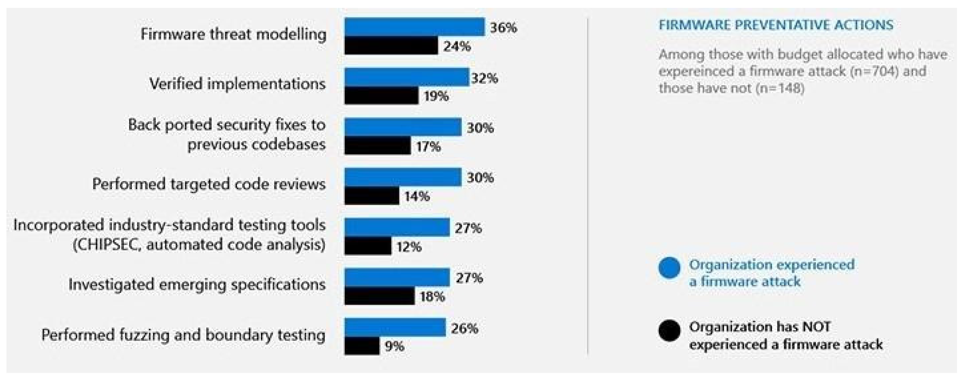
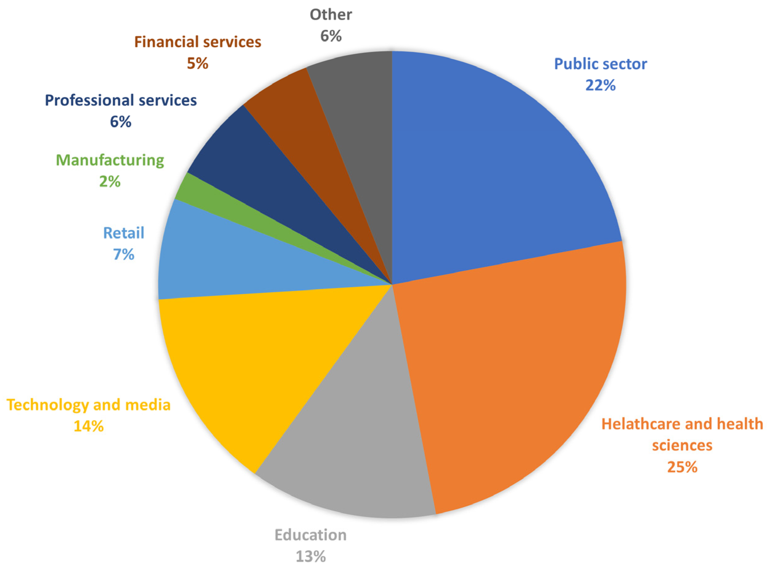
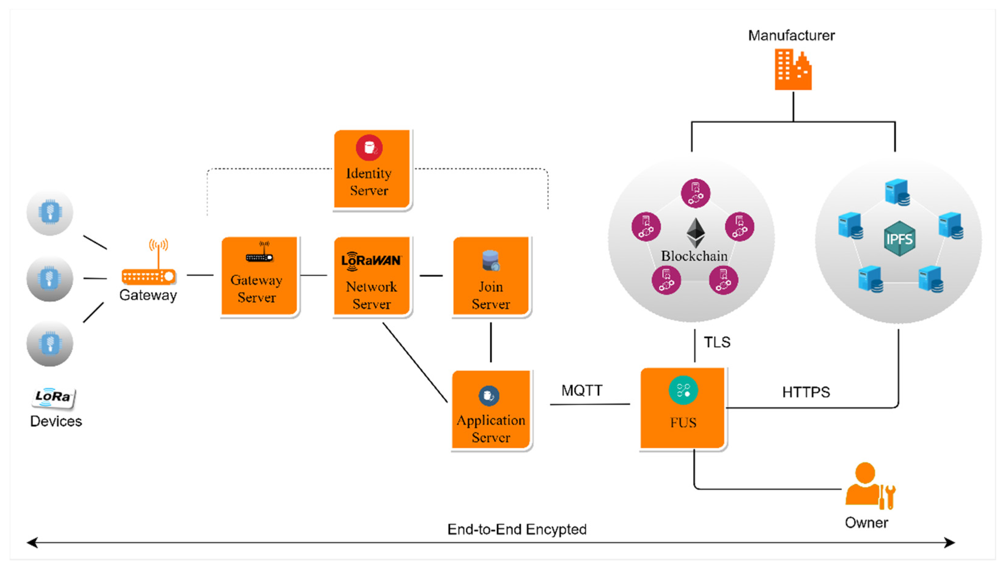
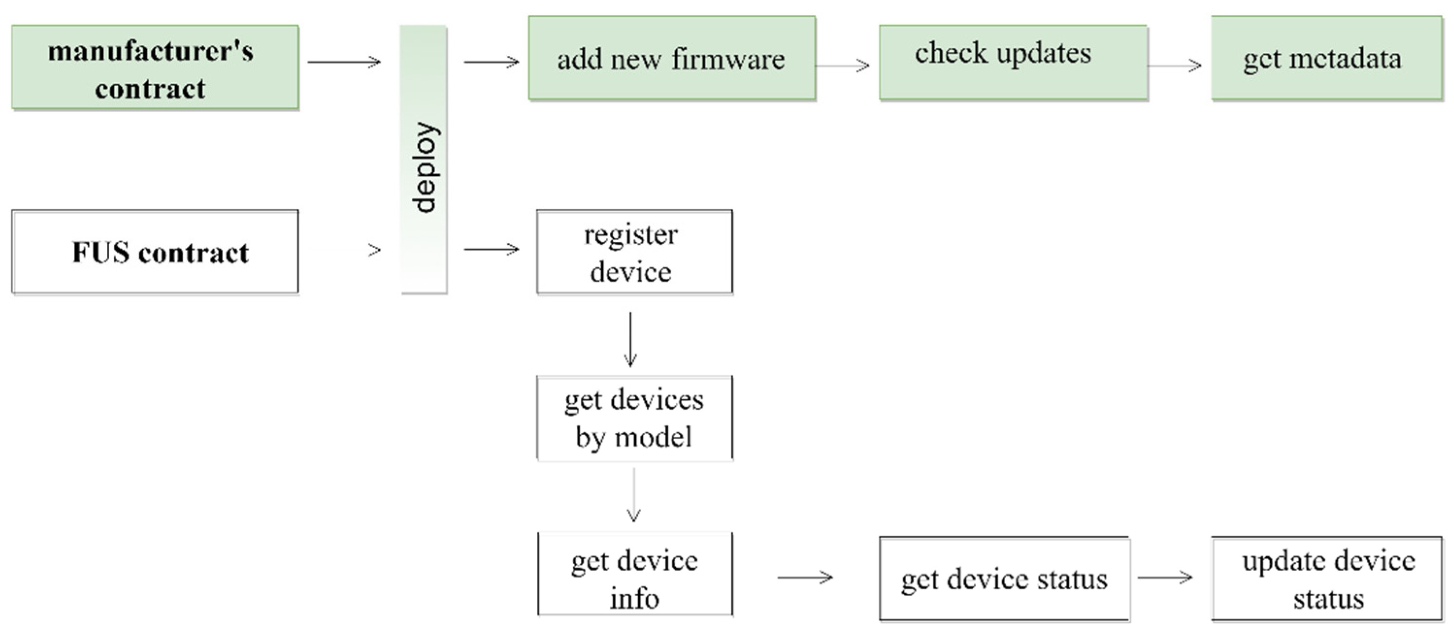
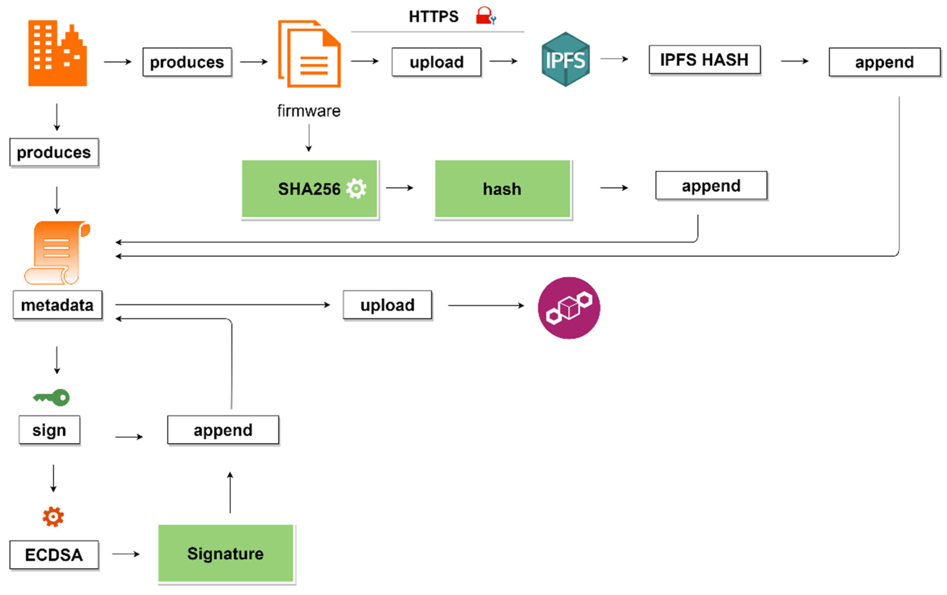
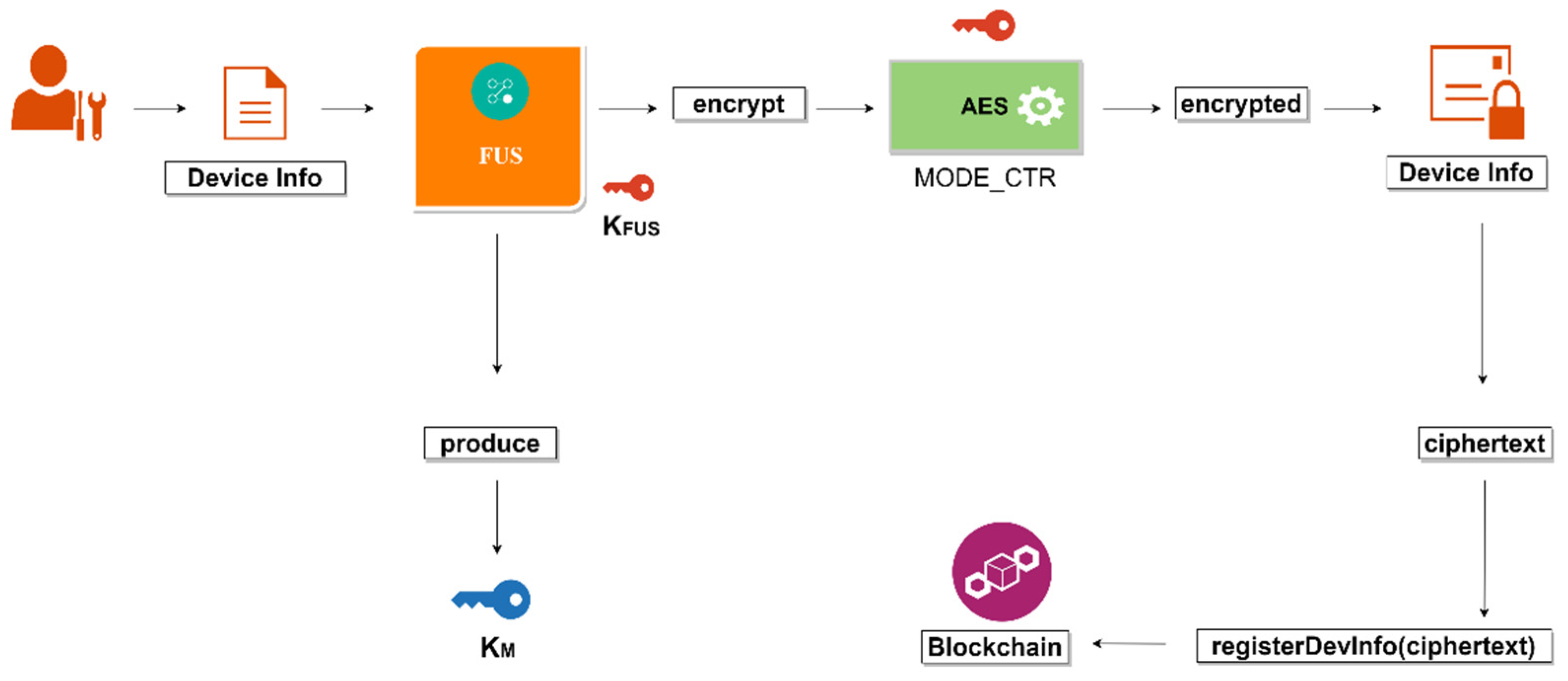
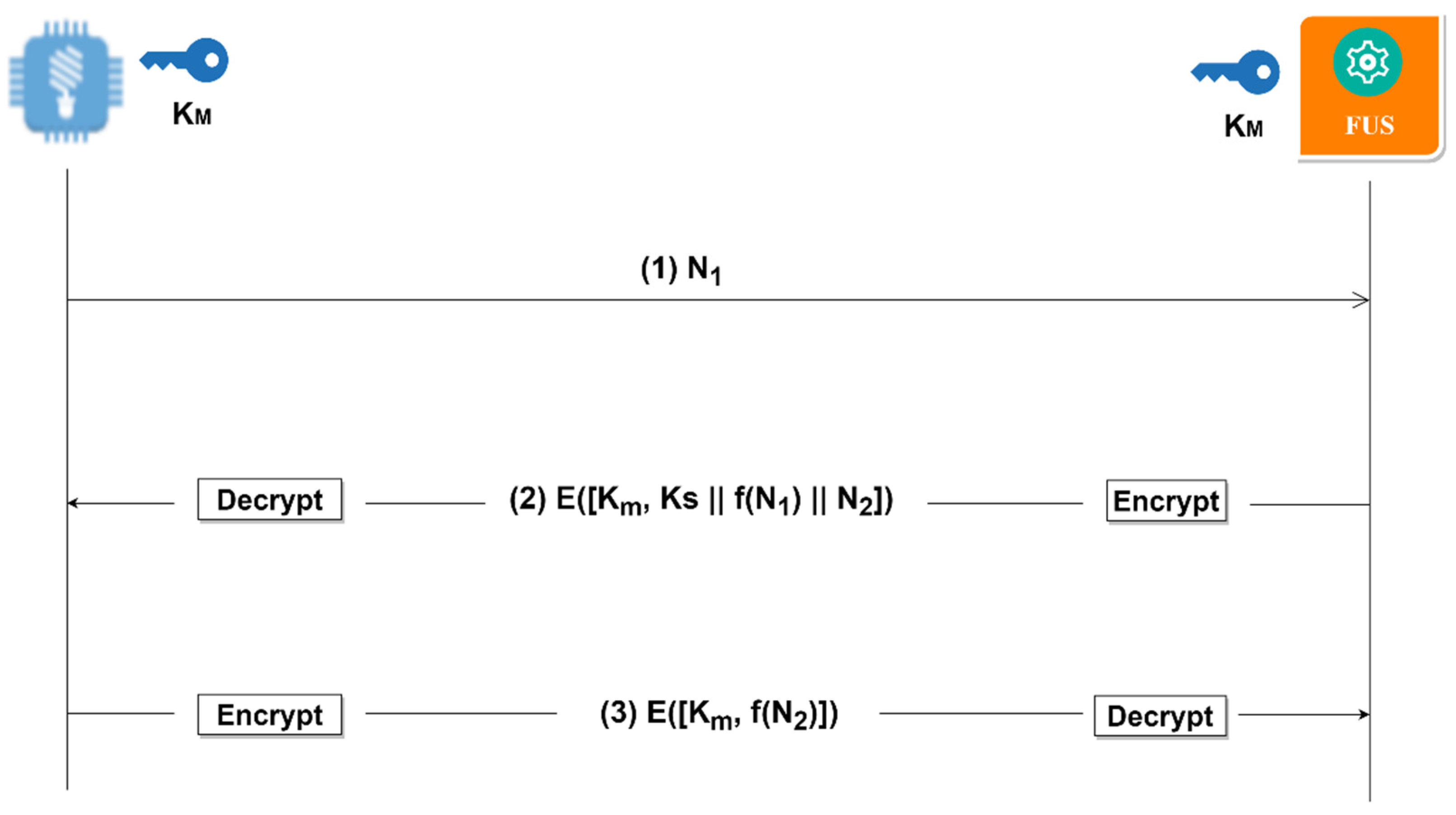
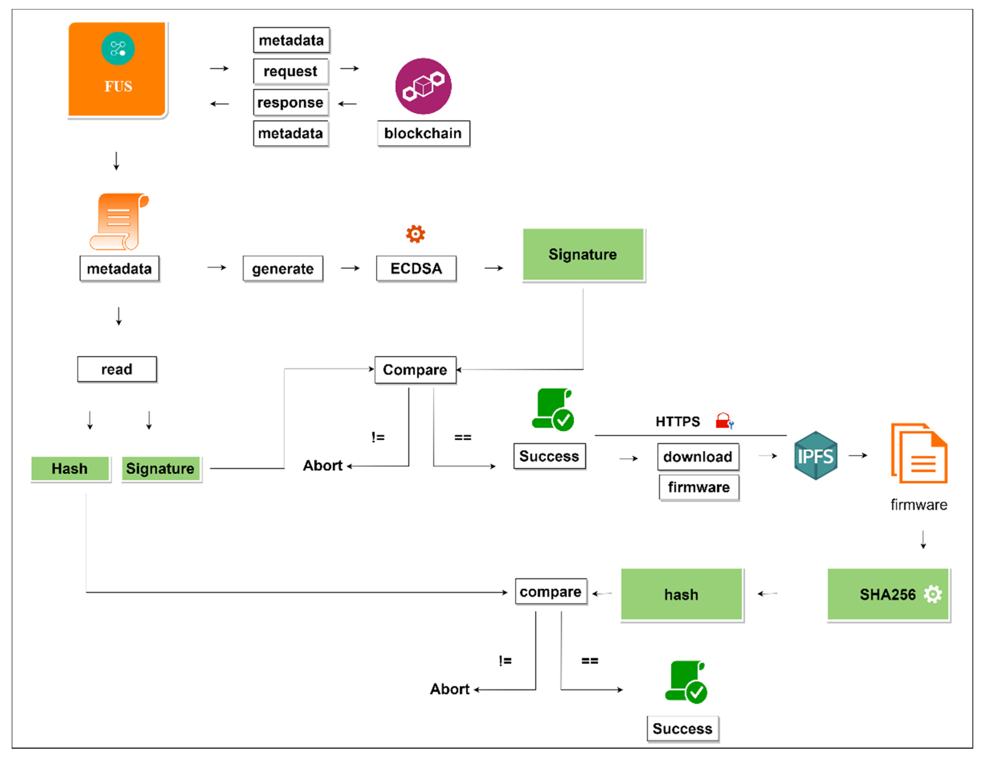
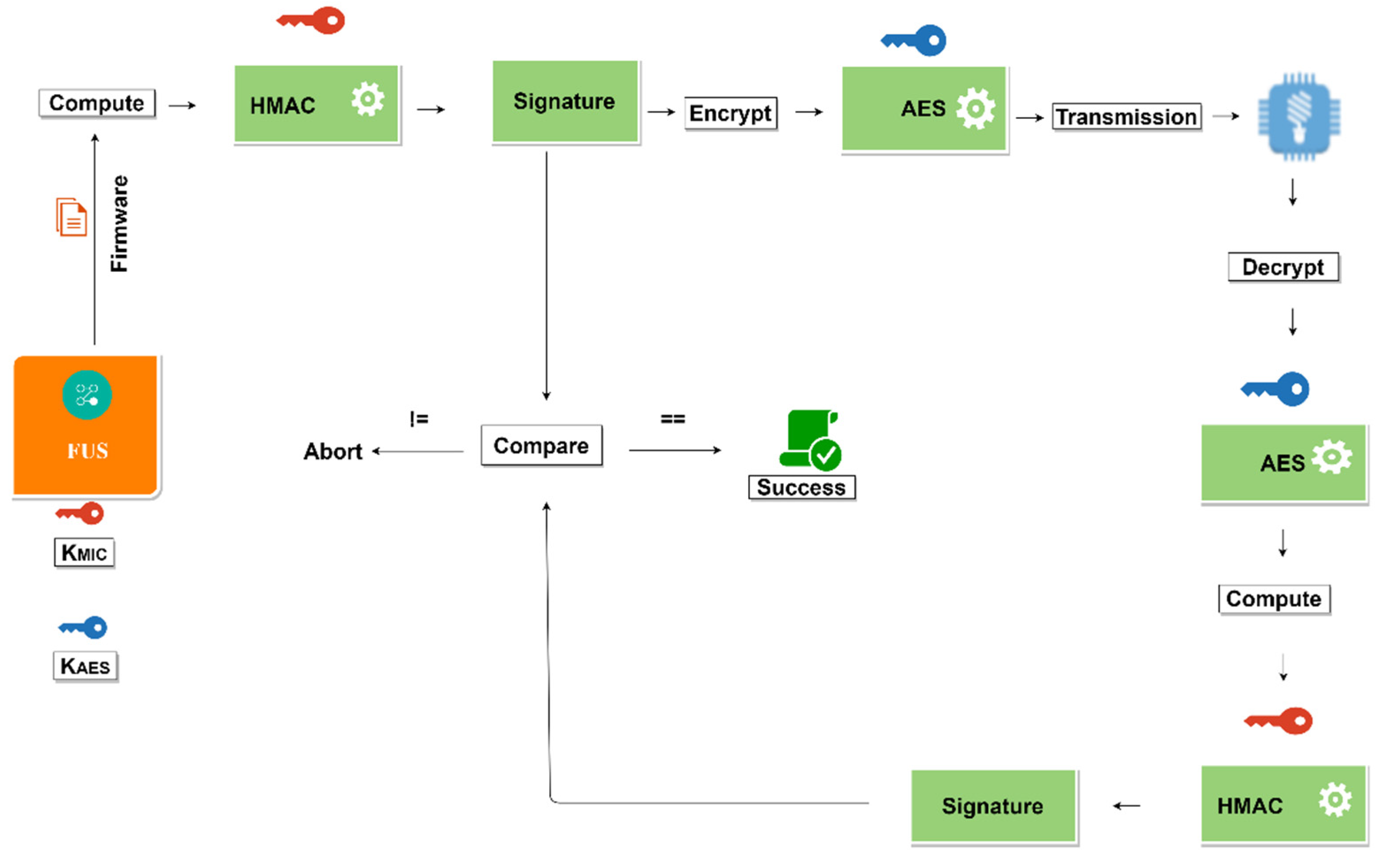
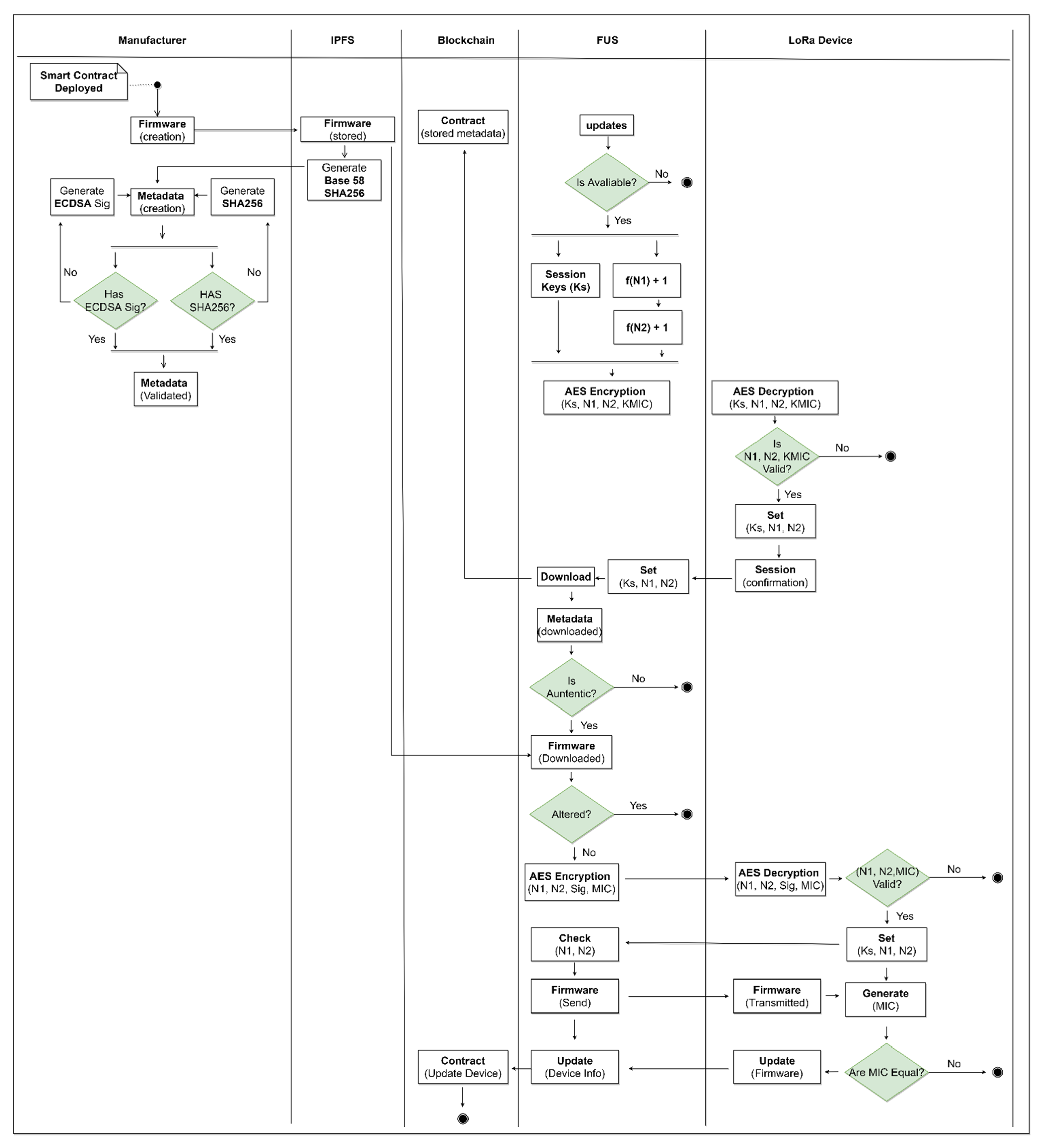
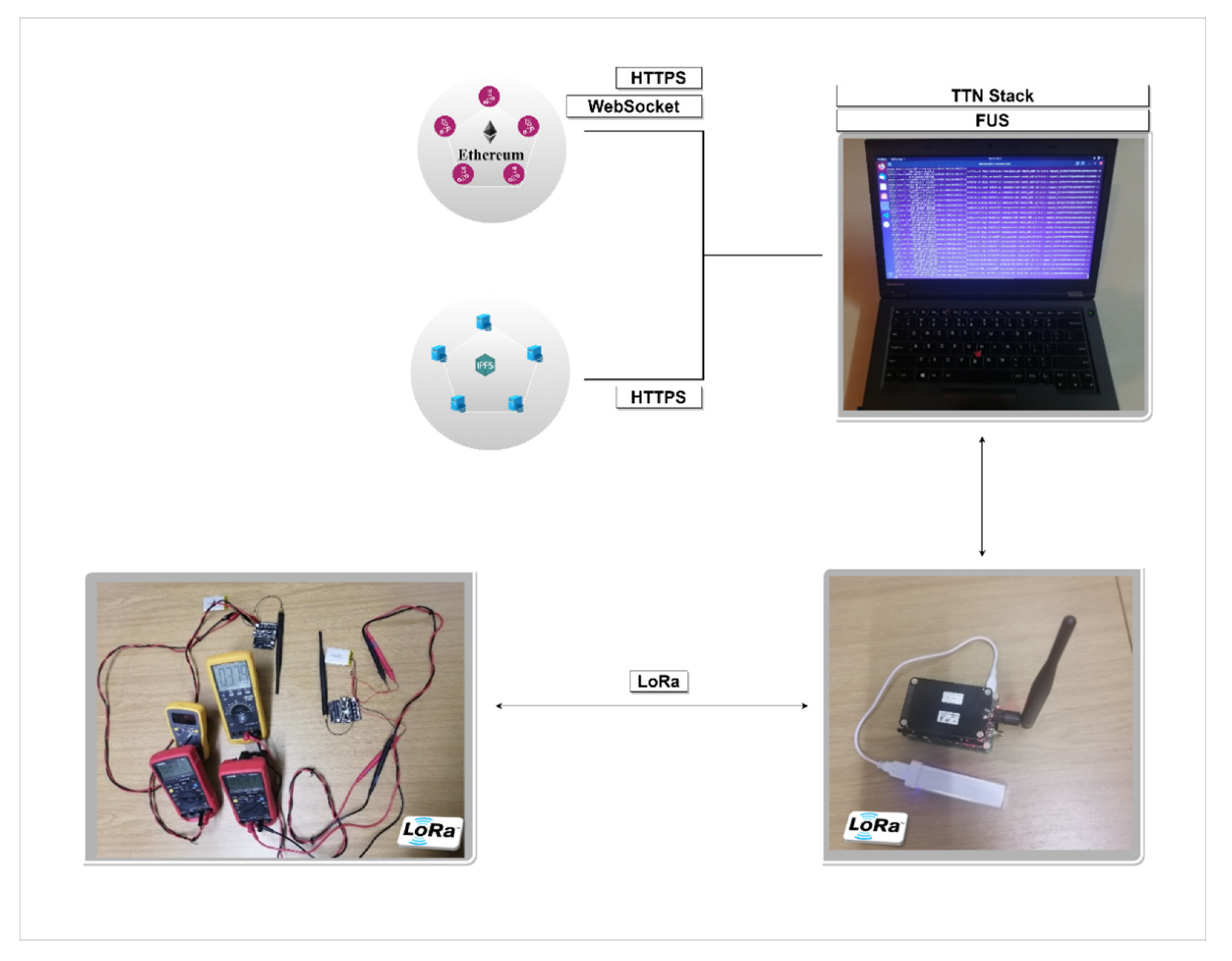
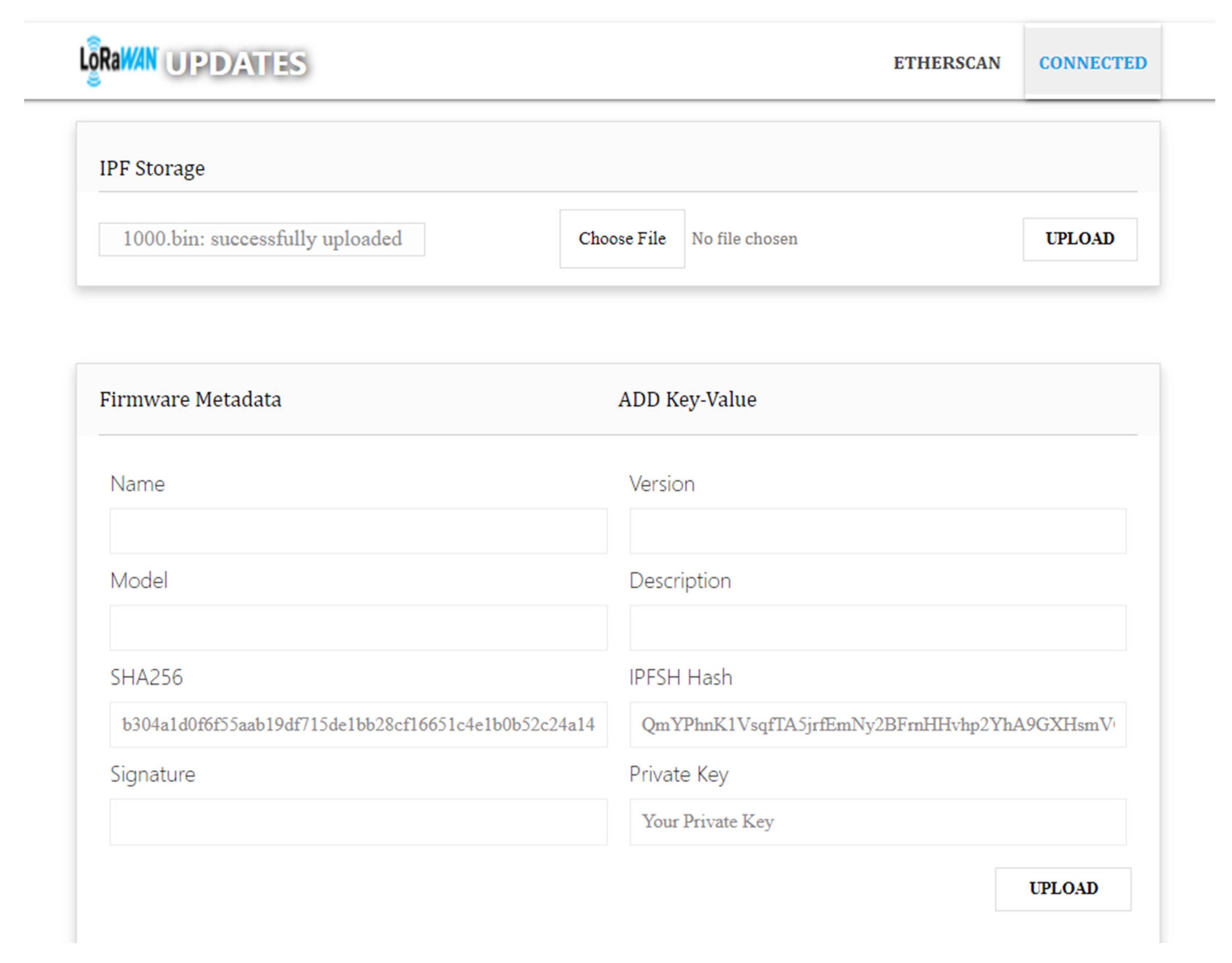
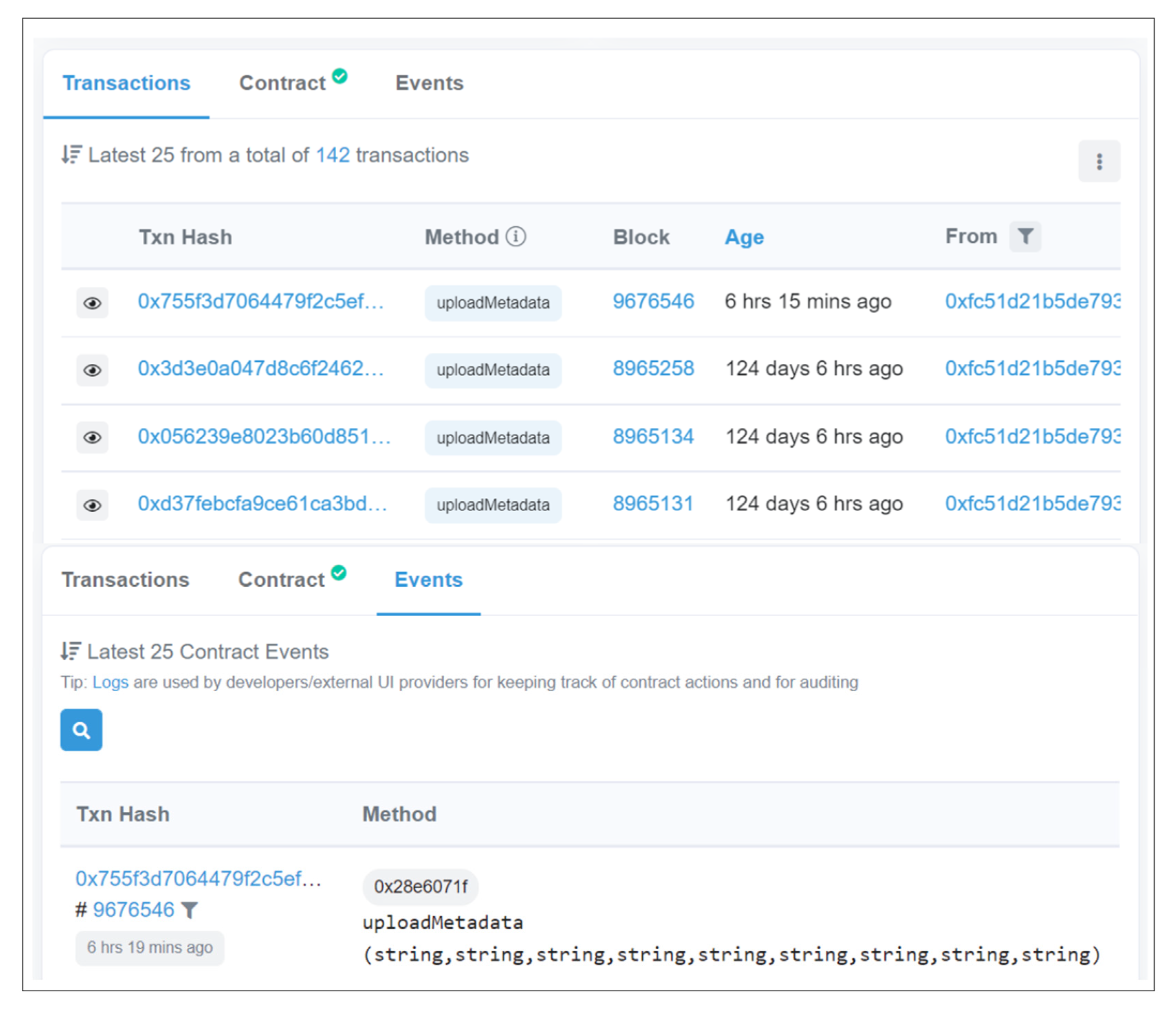
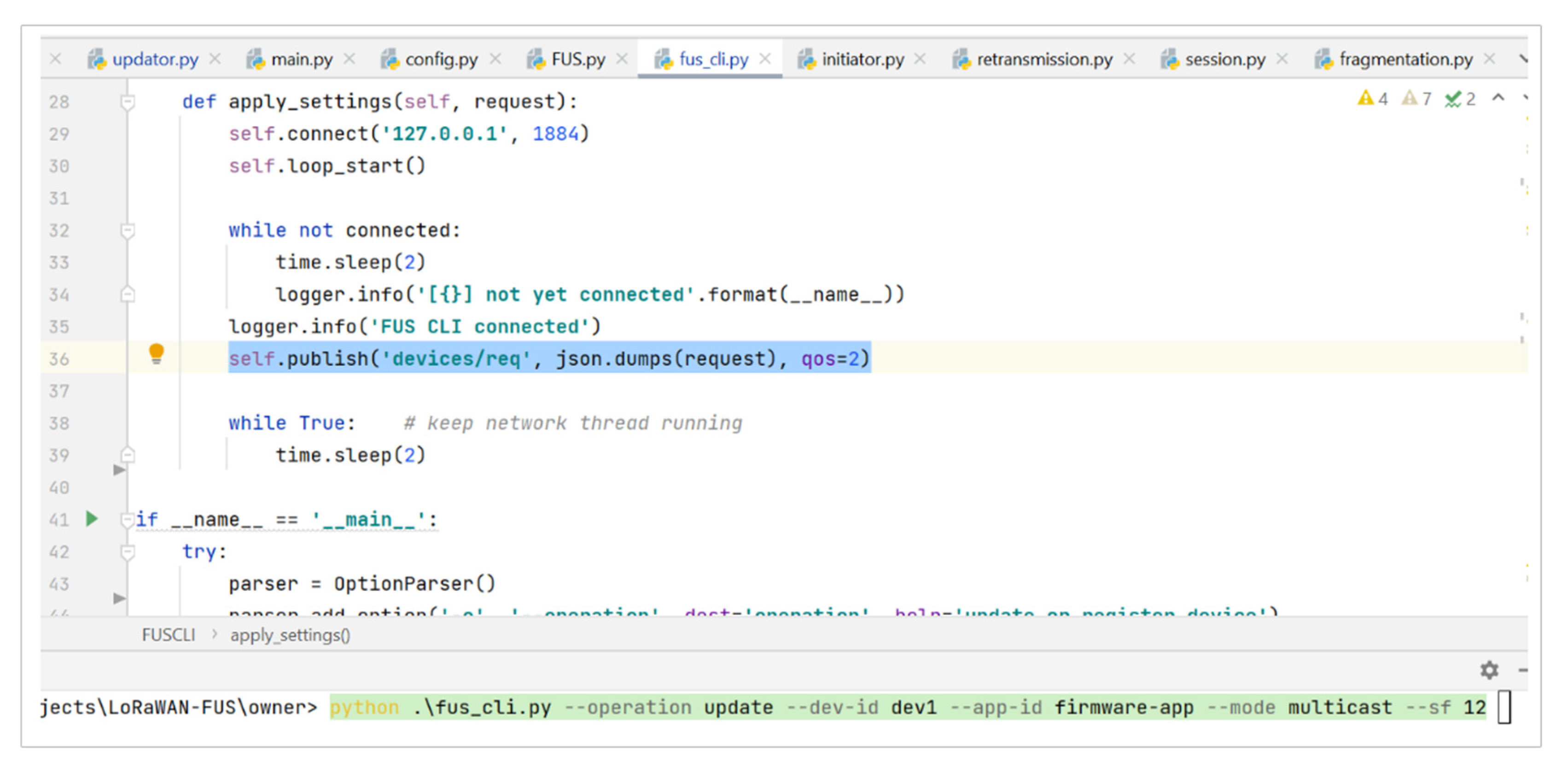
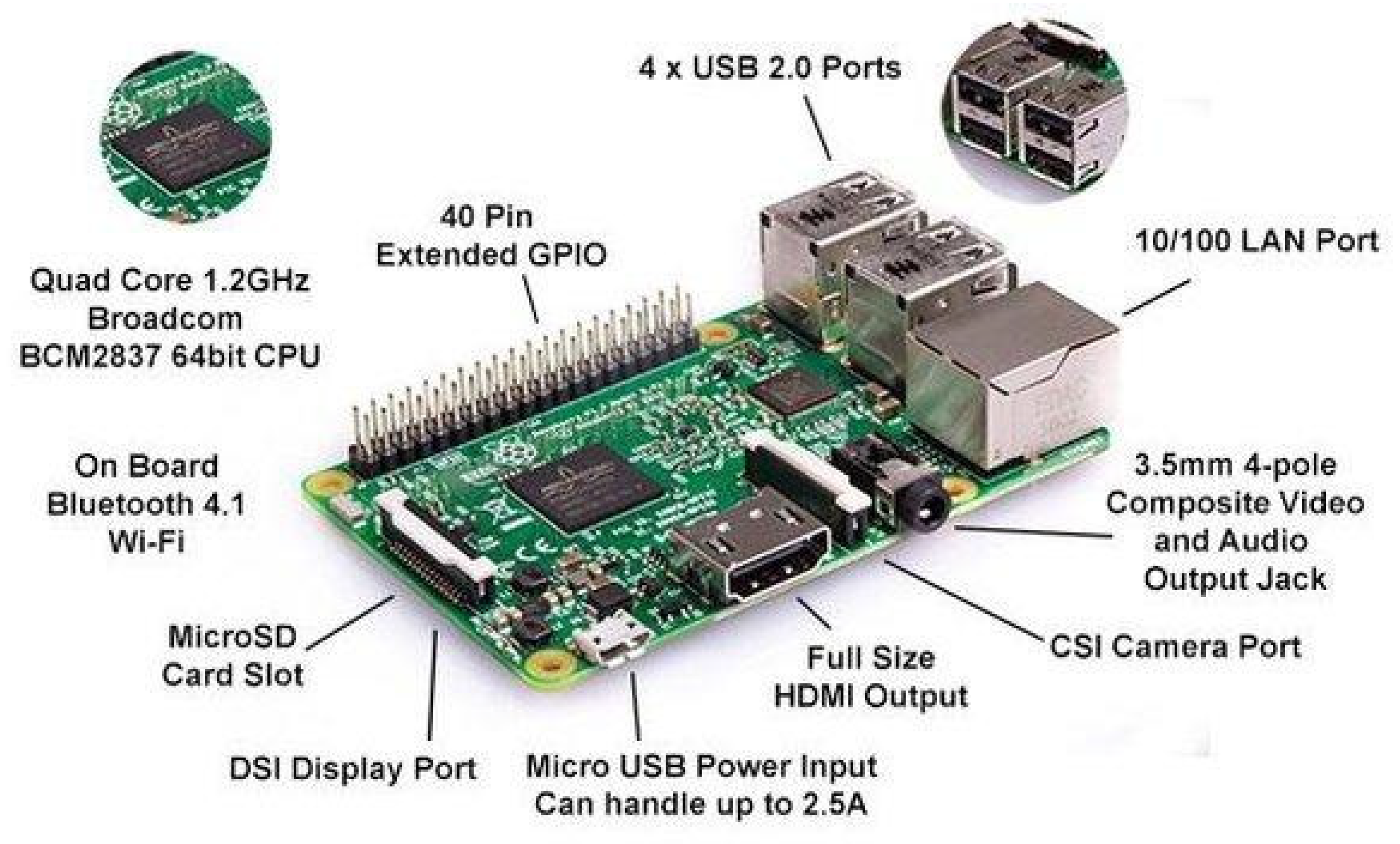
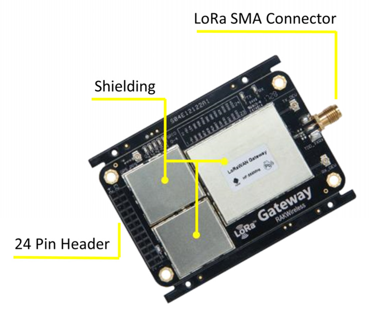
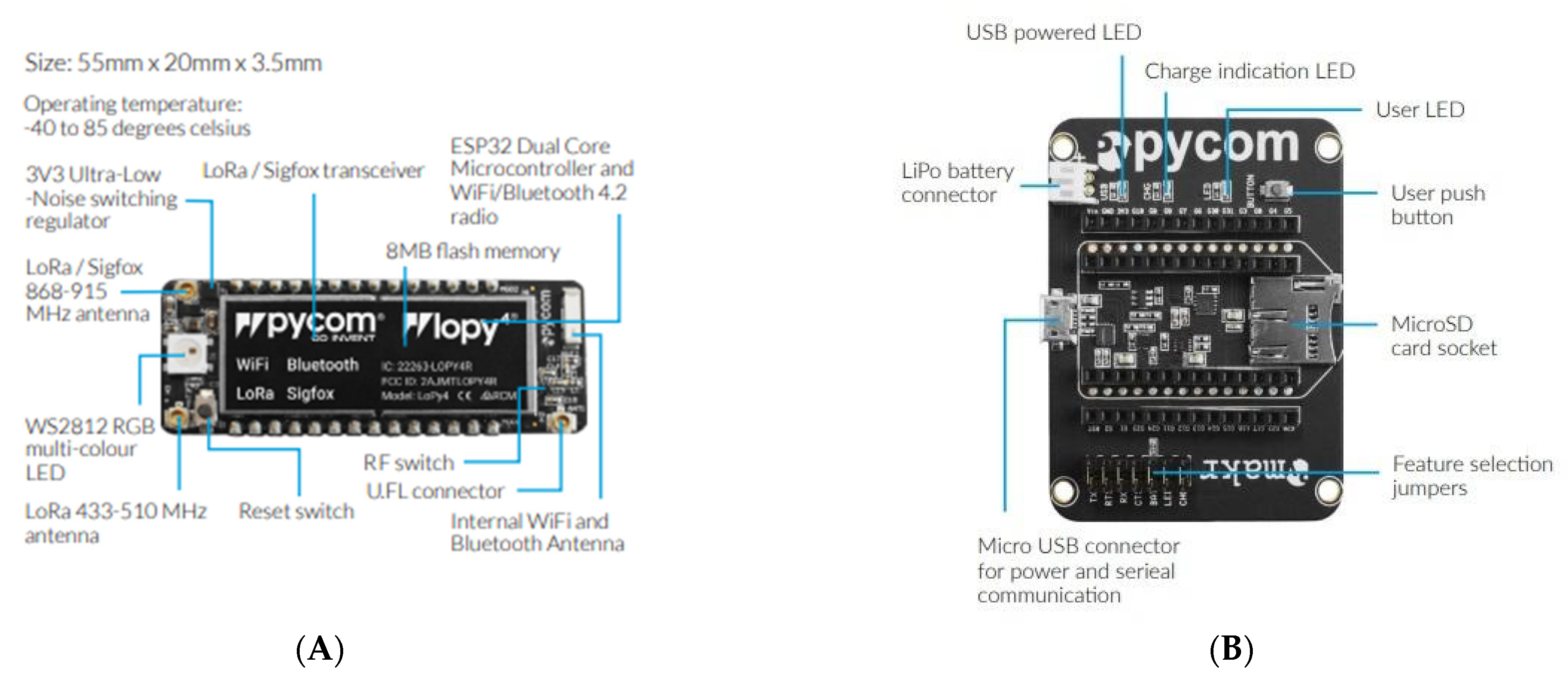
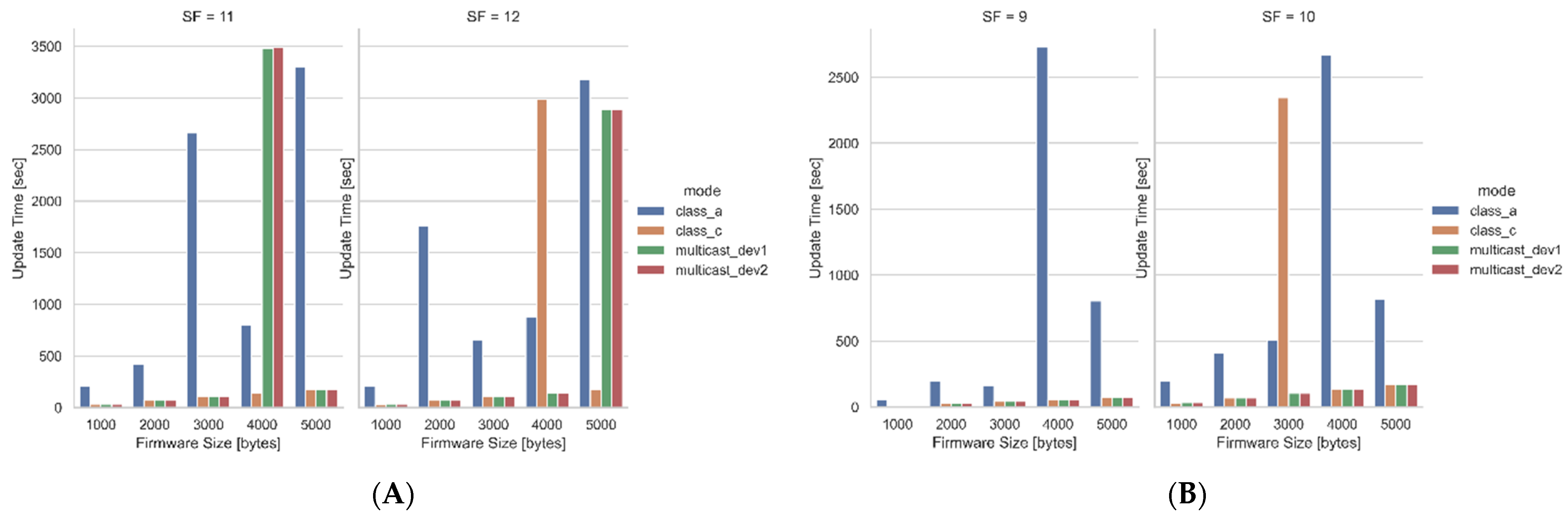
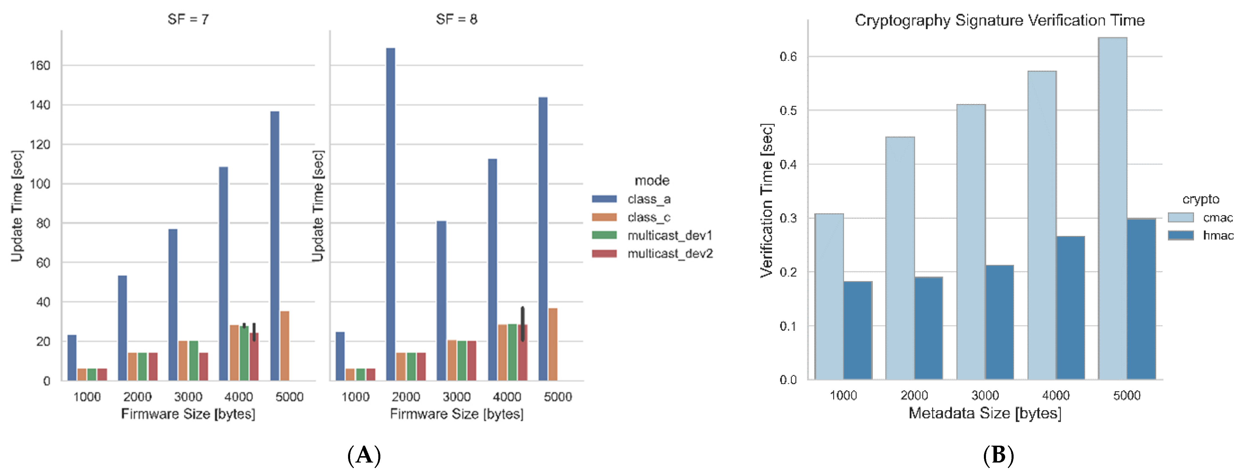
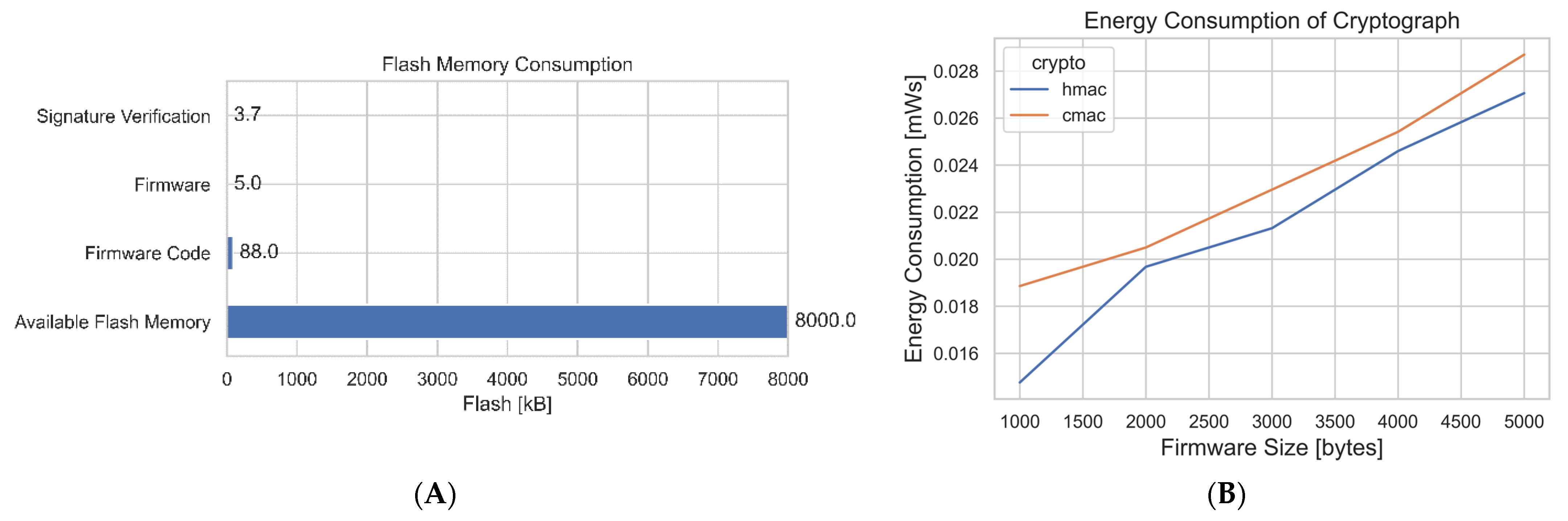
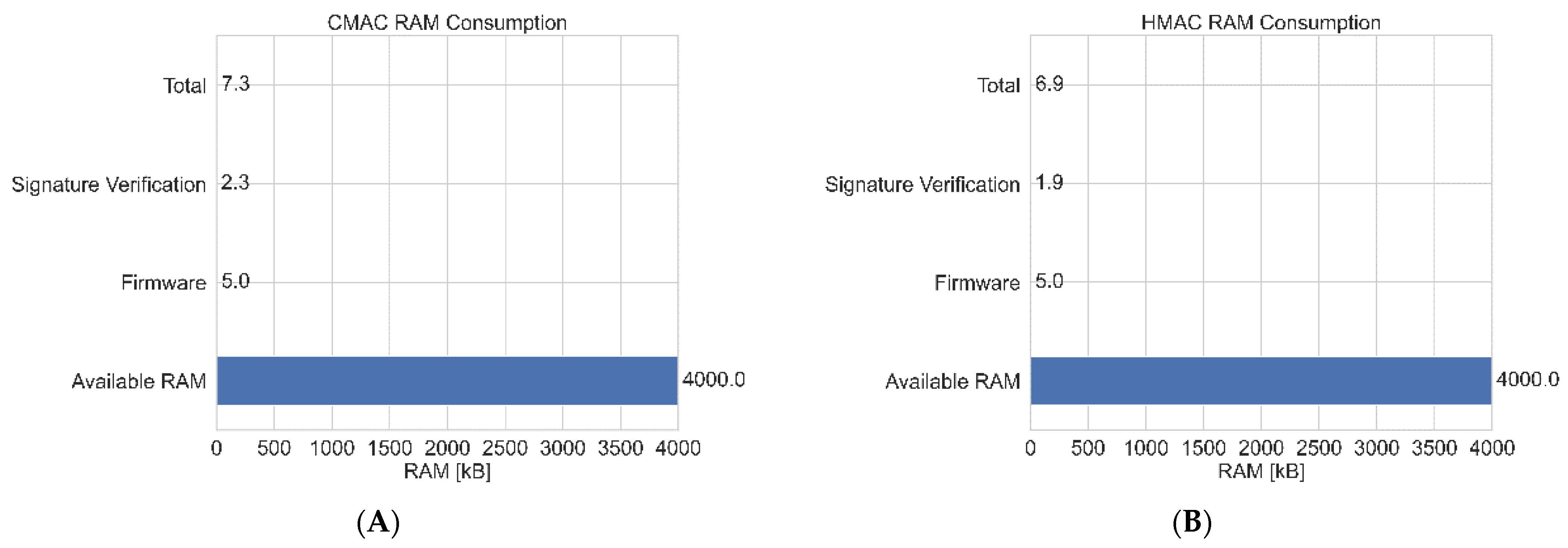
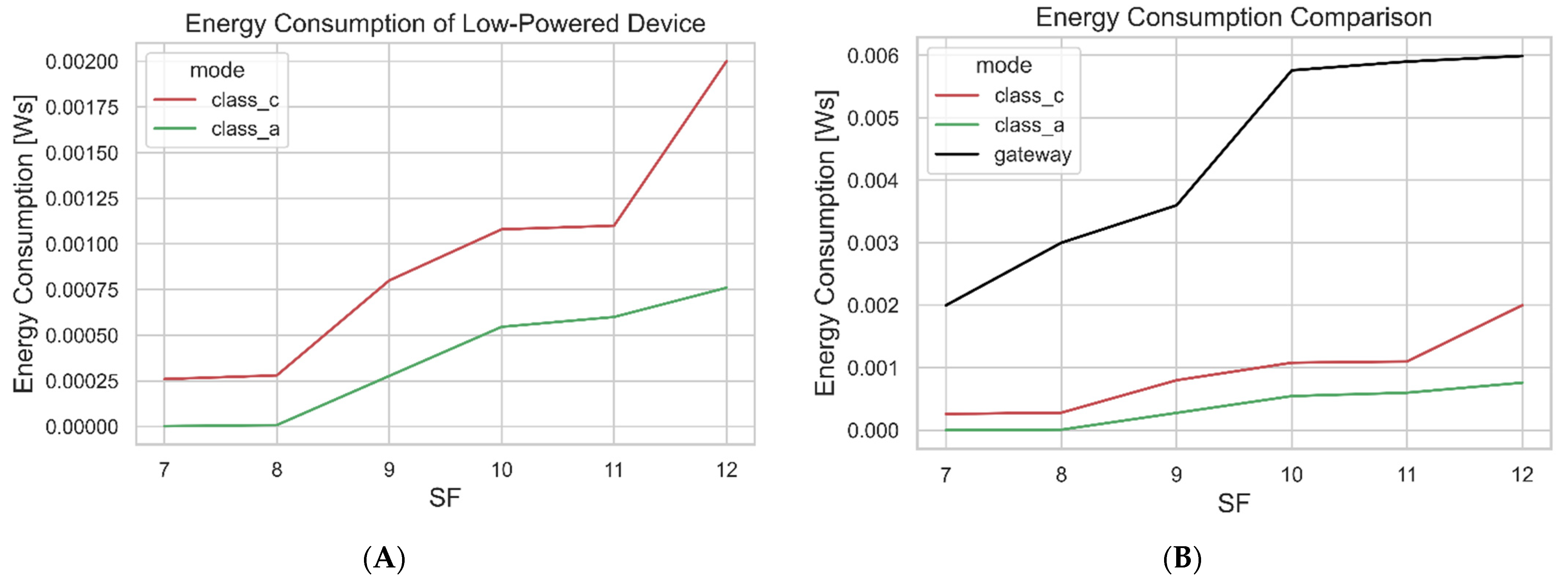
Table 1.
Classes of Constrained IoT devices [29].
Table 1.
Classes of Constrained IoT devices [29].
| Name | RAM | Flash |
|---|---|---|
| Class 0 | <<10 kB | <<100 kB |
| Class 1 | ~10 kB | ~100 kB |
| Class 2 | ~50 kB | ~250 kB |
Table 2.
Benefits and Limitations of the Firmware Update Models.
| References | Benefit(s) | Limitation(s) |
|---|---|---|
| [32] | Illustrated how Long-Range (LoRa) alliance firmware can be utilized to provide the firmware update to a large number of devices. | The work does not cover the security on how firmware can be protected during transmission. |
| [33] | Focus to deliver firmware updates to low-powered LoRa devices using both LoRa and Wi-Fi and the firmware image may be delivered fast in low-powered devices. | The approach requires that the end device must be equipped with Wi-Fi and, since Wi-Fi is a traditional technology, may consume more power of the end devices. |
| [34] | Illustrated and discussed the Blockchain-based scheme that provides high availability, integrity, and authentication in depth. | The proposed scheme may be difficult to incorporate in constrained IoT devices because of limited resources. |
| [35] | Demonstrated a Blockchain-based approach that shows how the integrity of firmware can be achieved. Provides a comparison between the proposed firmware update framework and existing frameworks. | The limited literature on firmware updates. The mechanism only ensures the integrity of the firmware image. No implementation and evaluation, only proposed the mechanism. |
| [36] | The work provides two ways of updating the IoT devices, the client–server and the distributed approaches. Discuss the implementation and analysis of these two techniques. | The proposed techniques are sufficient for IoT devices with good resources but not for devices that are limited in resources. |
| [37] | Discuss how low-powered devices can be updated based on the simulation tool developed by [14]. | The work performs firmware updates utilizing Blockchain, but it is not clear how the Blockchain was implemented and incorporated in the simulation tool developed by [14]. The mechanism claims to provide authenticity and integrity but does not specify which algorithms that were utilized to achieve these aims. Moreover, no security analysis was performed. |
| [38] | The work focuses on IoT networks and delivers updates to IoT devices using Ethereum Blockchain and IPFS. | The solution provided is not suitable for constrained networks and focuses on the IoT devices that have good processing power. Additionally, It provides only one security property, which is integrity. |
Table 3.
The Comparison Between the Firmware Update Mechanisms.
| Features and Properties | [32] | [33] | [34] | [35] | [36] | [37] | [38] |
|---|---|---|---|---|---|---|---|
| Target Low-End Devices | ✓ | ✓ | ✓ | ||||
| Target High-End Devices | ✗ | ✗ | ✓ | ✓ | ✓ | ✓ | |
| Availability | ✗ | ✗ | ✓ | ✓ | ✓ | ✓ | ✓ |
| Confidentiality | ✗ | ✗ | ✗ | ✗ | ✗ | - | ✗ |
| Integrity | ✗ | ✓ | ✓ | ✓ | ✓ | - | ✓ |
| Authentication | ✗ | ✗ | ✓ | ✓ | ✓ | - | ✗ |
| Data Freshness | ✗ | ✗ | ✗ | ✗ | ✗ | ✗ | ✗ |
| Constrained-Network | ✓ | ✓ | ✗ | ✗ | ✗ | ✓ | ✗ |
| Performance Evaluation | ✓ | ✗ | ✗ | ✗ | ✓ | ✓ | ✓ |
| Distributed/P2P | ✗ | ✗ | ✓ | ✓ | ✓ | ✓ | ✓ |
✓: Covered, ✗: Uncovered, (blank): Not clear.
Table 4.
FUS Tasks.
| Tasks | Description |
|---|---|
| Firmware requests | Handles and manages firmware requests by listening to Message Queuing Telemetry Transport (MQTT) topics. |
| Connects to decentralized networks | The Firmware Update Service (FUS) is connected to the InterPlanetary File System (IPFS) and Blockchain network via HyperText Transport Protocol Secure (HTTPS) and the WebSocket. Performs the firmware image requests and runs a daemon that listens for new firmware updates in the Blockchain network. It connects to both manufacturer’s smart contract and the FUS smart contract address. |
| State update | Continues updating the state of the device during the firmware update. |
| Firmware fragmentation | Performs firmware fragmentation using the device’s spreading factor (SF). |
| Cryptographic operations | Encrypts and decrypts sensitive data. Generates session keys to be used for that session of the firmware update. Performs authentication and integrity checks of the firmware image. |
Table 5.
Acronyms Used in the Security Model.
| Symbol | Meaning |
|---|---|
| KFUS | Firmware Update Service key |
| KM | Master Key or a shared secret key |
| KMW | Manufacturer’s wallet key |
| KS | Session keys |
| F(N) | Nonce update function |
| KPR | The private key of the manufacturer |
Table 6.
Development Environment and Libraries.
| Component | Environment and Libraries |
|---|---|
| Manufacturer Decentralized App | JavaScript, ReactJS, web3js, IPFS JavaScript API, MetaMask |
| Blockchain Smart Contract for Manufacturer and FUS | Solidity v 0.4.21, Truffle |
| LoRa Gateway | Raspberry pi + RAK831 |
| LoRaWAN Servers | TTN Stack v.3.12.3 |
| Blockchain Network | Ganache-cli, Infura Node |
| IPFS Network | Public Network: Infura Node |
| FUS | Web3py, paho-mqtt, IPFS–API |
Table 7.
Computer Specifications.
| Specifications | Description |
|---|---|
| Processor model | i5-4300M |
| Processor frequency | 2.6 GHz |
| Processor family | 4th gen Intel® Core™ i5 |
| RAM | 8 GB |
| Storage media | SSD |
Table 8.
Links to Datasheets.
| Specifications | Description |
|---|---|
| LoPy | https://pycom.io/wp-content/uploads/2017/11/lopy4Specsheet17.pdf (accessed date: 12 October 2021) |
| Pycom Expansion Board | https://docs.pycom.io/gitbook/assets/expansion3-specsheet-1.pdf (accessed date: 12 October 2021) |
| Raspberry Pi 3 Model B | https://static.raspberrypi.org/files/product-briefs/Raspberry-Pi-Model-Bplus-Product-Brief.pdf (accessed date: 12 October 2021) |
| RAK831 Module | https://docs.rakwireless.com/Product-Categories/WisLink/RAK831/Datasheet/ (accessed date: 12 October 2021) |
Table 9.
Experiment Parameters.
| Parameter | Description |
|---|---|
| RX1 Window | Both downlink and uplink |
| RX2 window | Downlink (869.525) |
| Region | EU (channels duty cycle 1% and 10%) |
| Gateway | 1 |
| Low-powered devices | 2 |
| Class mode | Class A and Class C |
| RX1 delay (class a) | 5 [s] |
| Bandwidth | LoRa.BW_125KHZ |
| SFs | 7–12 |
Table 10.
Gas Costs.
| Methods | Gas Cost Execution [gas] |
|---|---|
| uploadMetadata(1 kB) | 378,328 |
| uploadMetadata(2 kB) | 689,116 |
| uploadMetadata(3 kB) | 1,089,466 |
| uploadMetadata(4 kB) | 1,176,024 |
| uploadMetadata(5 kB) | 1,282,079 |
| registerDevice(devInfo) | 49,418 |
| updateDevInfo(devInfo) | 28,852 |
| retrieveMetadata() | 0 |
| retrieveDevsInfo() | 0 |
Table 11.
Algorithm Complexity.
| Algorithm | Complexity |
|---|---|
| Algorithm 1 | O (1) |
| Algorithm 2 | O (N) |
| Algorithm 3 | O (N) |
| Algorithm 4 | O (N) |
| Algorithm 5 | O (1) |
| Algorithm 6 | O (N) |
Table 12.
Exchanged Number of Messages During 1 kB of Firmware Fragment with SF12.
| Description | Number of Messages |
|---|---|
| Class A uplinks | 33 |
| Class A downlinks | 25 |
| Class C uplinks | 5 |
| Class C downlinks | 25 |
Table 13.
Property Comparison of the Proposed Model and State-of-the-Art Mechanisms.
| Features and Properties | [32] | [33] | [34] | [35] | [36] | [37] | [38] | Model |
|---|---|---|---|---|---|---|---|---|
| Target Low-End Devices | ✓ | ✓ | ✓ | ✓ | ||||
| Target High-End Devices | ✗ | ✗ | ✓ | ✓ | ✓ | ✓ | ||
| Availability | ✗ | ✗ | ✓ | ✓ | ✓ | ✓ | ✓ | ✓ |
| Confidentiality | ✗ | ✗ | ✗ | ✗ | ✗ | - | ✗ | ✓ |
| Integrity | ✗ | ✓ | ✓ | ✓ | ✓ | - | ✓ | ✓ |
| Authentication | ✗ | ✗ | ✓ | ✓ | ✓ | - | ✗ | ✓ |
| Data Freshness | ✗ | ✗ | ✗ | ✗ | ✗ | ✗ | ✗ | ✓ |
| Constrained-network | ✓ | ✓ | ✗ | ✗ | ✗ | ✓ | ✗ | ✓ |
| Performance Evaluation | ✓ | ✗ | ✗ | ✗ | ✓ | ✓ | ✓ | ✓ |
| Distributed/P2P | ✗ | ✗ | ✓ | ✓ | ✓ | ✓ | ✓ | ✓ |
✓: Covered, ✗: Uncovered, (blank): Not clear.
Publisher’s Note: MDPI stays neutral with regard to jurisdictional claims in published maps and institutional affiliations. |
© 2022 by the authors. Licensee MDPI, Basel, Switzerland. This article is an open access article distributed under the terms and conditions of the Creative Commons Attribution (CC BY) license (https://creativecommons.org/licenses/by/4.0/).
Share and Cite
MDPI and ACS Style
Mtetwa, N.S.; Tarwireyi, P.; Sibeko, C.N.; Abu-Mahfouz, A.; Adigun, M. Blockchain-Based Security Model for LoRaWAN Firmware Updates. J. Sens. Actuator Netw. 2022, 11, 5. https://0-doi-org.brum.beds.ac.uk/10.3390/jsan11010005
AMA Style
Mtetwa NS, Tarwireyi P, Sibeko CN, Abu-Mahfouz A, Adigun M. Blockchain-Based Security Model for LoRaWAN Firmware Updates. Journal of Sensor and Actuator Networks. 2022; 11(1):5. https://0-doi-org.brum.beds.ac.uk/10.3390/jsan11010005
Chicago/Turabian StyleMtetwa, Njabulo Sakhile, Paul Tarwireyi, Cecilia Nombuso Sibeko, Adnan Abu-Mahfouz, and Matthew Adigun. 2022. "Blockchain-Based Security Model for LoRaWAN Firmware Updates" Journal of Sensor and Actuator Networks 11, no. 1: 5. https://0-doi-org.brum.beds.ac.uk/10.3390/jsan11010005
Note that from the first issue of 2016, this journal uses article numbers instead of page numbers. See further details here.