Thermal Effects in Slender EHL Contacts


1
Gear Research Center (FZG), Department of Mechanical Engineering, School of Engineering & Design, Technical University of Munich, Boltzmannstraße 15, 85748 Garching bei München, Germany
2
Division of Machine Elements, Luleå University of Technology, 97187 Luleå, Sweden
*
Author to whom correspondence should be addressed.
Lubricants 2022, 10(5), 89; https://0-doi-org.brum.beds.ac.uk/10.3390/lubricants10050089
Submission received: 8 March 2022
/
Revised: 16 April 2022
/
Accepted: 28 April 2022
/
Published: 6 May 2022
(This article belongs to the Topic Tribology: Latest Advances and Prospects)
Abstract
:This study deals with experimental and numerical analysis of the thermal effects of slender elastohydrodynamically lubricated (EHL) contacts under high sliding. Thereby, the entrainment direction is along the major axis of the contact ellipse. Film thickness measurements were carried out on an optical EHL tribometer with a glass disk and steel roller. Numerical EHL solutions were obtained with consideration for non-Newtonian rheology and thermal effects. The results show that thermal effects can result in a strong viscosity wedge diverting oil flow to the contact sides. For high positive sliding, in which the glass disk moves faster, the influence of entrainment speed on minimum film thickness is almost negligible, while the film thickness shows a continuous decrease in gap length direction.
1. Introduction
Machine elements with rolling-sliding contacts, such as rolling bearings, gears, and cam followers, are characterized by elastohydrodynamic lubrication (EHL). A typical hard EHL contact features a submicrometer-thin lubricant film with a pressure of up to several GPa. For such a high pressure to develop in the lubricant film, the contacting surfaces need to form a geometrically converging gap through which they entrain the lubricant. As the lubricant passes through, the pressure, and consequently the viscosity, of the lubricant increases. The highly pressurized lubricant film exerts an elastic deformation on the contacting surfaces, facilitating their separation, and resulting in low wear and friction. The EHL film thickness is mainly affected by the effective viscosity in the contact inlet, while the EHL friction is determined by the conditions in the contact.
Many experimental and numerical studies have been conducted in search of EHL film forming mechanisms under a variety of rolling-sliding conditions. In terms of elliptical point contacts, these relate in particular to configurations in which the main lubricant entrainment direction coincides with the minor axis of the contact ellipse, so-called wide elliptical contacts. In contrast, there are surprisingly few studies that consider narrow elliptical or so-called slender contacts, in which the lubricant entrainment direction coincides with the major axis of the contact ellipse. Worm gears are a typical example of machine elements with slender contacts [1], but they are also characteristic of other gear applications [2,3,4] and are found at the roller-flange interface in cylindrical and tapered rolling element bearings [3,5]. When designing such machine elements, it is of great importance to understand the relationships and characteristics of slender EHL contacts and to determine the underlying mechanisms.
A major breakthrough in the field of EHL occurred in 1963, when Gohar and Cameron [6] successfully applied the optical interferometry technique to measure oil film thickness in point contacts and presented the interference pattern of a classic horseshoe-shaped circular EHL contact in their paper. In 1972, Thorp and Gohar [7] applied optical interferometry to slender EHL contacts. Their film thickness interferograms show a flat plateau in the central region with two minima in the side lobes. In 1982, Mostofi and Gohar [4] developed a numerical model of elliptical EHL contacts involving solving the Reynolds equation under isothermal conditions. They varied the direction of the rolling velocity to obtain wide and slender contact configurations and derived a simple analytical formula that describes the minimum film thickness in dependence on ellipticity, dimensionless speed, load, and material parameters. In 1983, Evans and Snidle [5] analyzed heavily loaded slender EHL contacts under pure rolling and isothermal conditions. They found a discrepancy in the minimum film thickness when compared to the analytical results obtained by Mostofi and Gohar. In 1985, Chittenden et al. [8] performed extensive numerical studies under isothermal conditions and derived minimum and central film thickness formulae for a wide range of ellipticity ratios, including wide and slender elliptical contacts. In 2016, Wheeler et al. [9] and in 2020 Marian et al. [10] found that the formulae proposed by Chittenden et al. are only valid within a very limited range of dimensionless load and material parameters. In 2010, Venner et al. [2] performed a numerical study on slender EHL contacts under isothermal conditions. They discovered that the ratio of central to minimum film thickness depends strongly on the ellipticity and load conditions, and stressed the necessity for improved film thickness formulae for slender EHL contacts. In 2016, Wheeler et al. [11] studied the role of ellipticity in a range of slender to wide elliptical configurations, assuming Newtonian behavior and isothermal conditions. They found that wide elliptical contacts are greatly influenced by backflow and slender elliptical contacts by side flow. In 2021, Wolf et al. [3] used a multilevel isothermal EHL solver to derive a new central film thickness formula for slender contacts with variable ellipticity. The central film thickness formula devised by the authors displays a greater accuracy than that by Chittenden et al. [8]. In their latest work [12], Wolf et al. validated their formula for pure rolling conditions by comparison with the experimental data.
In the aforementioned parametric numerical studies on slender EHL contacts, the primary focus was on developing simple analytical formulae that describe how the central and minimum film thickness varies with ellipticity ratio, operating conditions and material properties, taking into consideration Newtonian rheology and isothermal conditions. However, rheological and thermal effects play a dominant role under rolling-sliding conditions. The importance of thermal effects in elliptical contacts can be observed in the experimental work performed by Kaneta et al. [13] in 2000. The authors studied elliptical contacts in pure sliding conditions and with different angles of oil entrainment using optical interferometry. In both wide and slender elliptical EHL contacts, they found conical depressions in the film thickness, known as ‘dimples’ and attributed them at the time to the so-called ‘squeeze film effect’. In later work [14,15] it was attributed to the ‘temperature-viscosity wedge’ effect. Another important study in this context was performed by Sharif et al. [1] in 2001. By considering the realistic geometry of worm gears, non-Newtonian rheology, and thermal effects, the authors performed a numerical analysis of elliptical contacts in worm gears, in which the main entrainment direction is at an angle or coincides with the major axis of the contact ellipse. They found that the formulae proposed by Chittenden et al. [8] significantly overestimated the film thickness due to the isothermal effects considered in the process of their development.
The literature review shows that slender EHL contacts have been rarely studied in literature. No study has addressed thermal effects in slender EHL contacts for different rolling-sliding conditions systematically, especially not in comparison to circular EHL contacts. This study will show relevant particularities of slender thermal EHL (TEHL) contacts that should be considered when designing machine elements. The focus is on the influence of thermal effects on film thickness as well as on understanding the underlying mechanisms. Different entrainment speeds and slide-to-roll ratios are considered, and the obtained results are compared against circular EHL contact configurations.
2. Methods
Experimental and numerical investigations are conducted to investigate the thermal effects of slender EHL contacts. The tribometer and operating conditions are described at the beginning of the section, followed by a detailed description of the numerical model.
2.1. Experimental Investigation
The experimental investigation employed an optical EHL tribometer based on thin film colorimetric interferometry. Figure 1 shows the mechanical layout of the tribometer.
The EHL contact is formed between a glass disk (2) and a counter steel body (1). Different types of counter bodies are used to create the slender and circular contacts. For the slender contact, a tire-shaped roller was produced with a radius of curvature of in the rolling-sliding direction and of in the transversal direction, resulting in an ellipticity ratio . For the circular contact, a standard steel ball with a diameter of is used. Both types of counter bodies were surface-hardened and mechanically polished to an arithmetic mean roughness of . The load is applied by a dead-weight lever mechanism. The speeds of the disk and the counter body are controlled by two electric motors. The entrainment speed and the slide-to-roll ratio are defined as:
The contact side of the glass disk is coated with a very thin, semi-reflective, chromium layer. The contact area is illuminated by a high-intensity lamp, observed through an industrial microscope, and recorded with a high-speed camera. When a light beam illuminates the lubricant film in the EHL contact, due to the chromium layer that serves as a beam splitter, the light is reflected from the steel surface and from the chromium layer. The superimposed reflected beams form an optical interference pattern, which is evaluated in accordance with the theory of thin film colorimetric interferometry developed by Hartl et al. [17] and Molimard et al. [18]. The optical interference pattern is converted to a quantitative lubricant film thickness by the color-matching algorithm and color-film thickness calibration integrated in the AChILES software developed by Hartl and his team.
All experiments were conducted at a Hertzian pressure of and an oil temperature of . To cover different rolling-sliding conditions, three types of motion were investigated:
- pure rolling ;
- negative sliding (counter steel body moves faster than glass disk);
- positive sliding (glass disk moves faster than counter steel body).
2.2. Numerical Investigation
The experimental investigations are accompanied by numerical modelling of the EHL contact. A fully-flooded contact with ideally smooth surfaces and steady-state conditions is considered.
2.2.1. Governing Equations
To determine the fluid flow, the generalized Reynolds equation for point contacts with unidirectional lubricant entrainment in gap length direction () is solved. The generalized Reynolds equation in dimensionless form reads [21]:
where
Cavitation is treated by adding the penalty term to the Reynolds equation. The ellipticity parameter is determined according to Nijenbanning et al. [22]. The special case when corresponds to the circular contact, for which: . The velocity and shear stress in dimensionless form are defined by Equations (4) and (5), respectively [21]:
The dimensionless energy equations for fluid and solids are defined by Equations (6) and (7), respectively:
The film thickness equation reads:
The elastic deformation of an equivalent body is obtained by solving the linear elasticity equation, which reads:
where
The applied load and generated fluid pressure are balanced using the load balance equation, which reads:
The Vogel model in Equation (12) [23,24,25] and Roelands model in Equation (13) [26] describe the pressure and temperature dependence and the Ree–Eyring model in Equation (14) [27] describes the rheology of the oil MIN100:
The value of the Eyring stress is set to . Oil density is modeled with the Bode model [28], which reads:
The thermal conductivity and specific heat capacity per volume are described by the models of Larsson and Andersson for paraffinic mineral oils [29]:
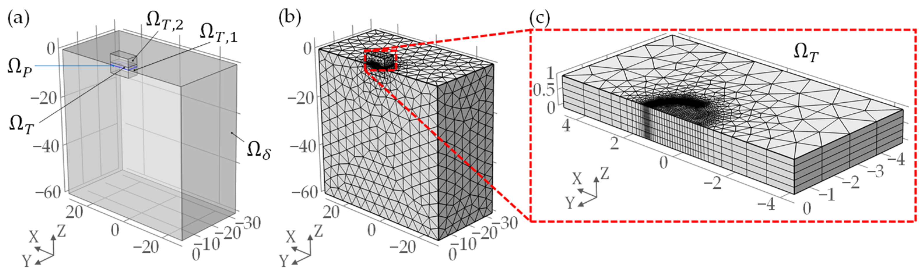
2.2.2. Computational Domain and Meshing
The Reynolds equation is solved on the two-dimensional domain , while the energy equations for fluid and solids are solved on the three-dimensional computational domains , and , as shown in Figure 2. Unidirectional oil entrainment in the -direction guarantees symmetric film thickness distribution with respect to the – plane passing through the contact center at . Hence, the complete problem is solved on one half of the computation domains. The pressure field obtained from the Reynolds equation is mapped in the gap height direction. The shear stress equation in the gap height direction is solved by the shear stress distribution over the two-dimensional oil film domain, and the oil properties variation with pressure, temperature and shear stress over the entire oil film domain are thus obtained.
The numerical model is based on the work by Habchi [21] and Ziegltrum et al. [19,30]. Triangular and tetrahedral elements are used for the domains , , and . For , a finer mesh is used in the regions where high-pressure gradients are expected to occur, that is, within the contact area and at the location of the second pressure maximum. In the gap height direction, uniformly distributed prism elements are used, which speeds up the computation of the integral terms [21].
Reynolds, energy and linear elasticity equations are written in a weak form, as a convection-diffusion type. Due to the high Peclet numbers ( in the fluid domain, for the highest considered entrainment speed), Streamline Upwind Petrov Galerkin (SUPG) and Galerkin Least Squares (GLS) stabilization terms are applied to the energy equation. The weak form of the equations is transferred to dimensionless form and solved by the finite element method (FEM), using the full-system approach for the generalized Reynolds equation and the linear elasticity equation, with strong coupling of this system of equations with the energy equation. Further details on the equations and numerical procedure used can be found in [19,30].
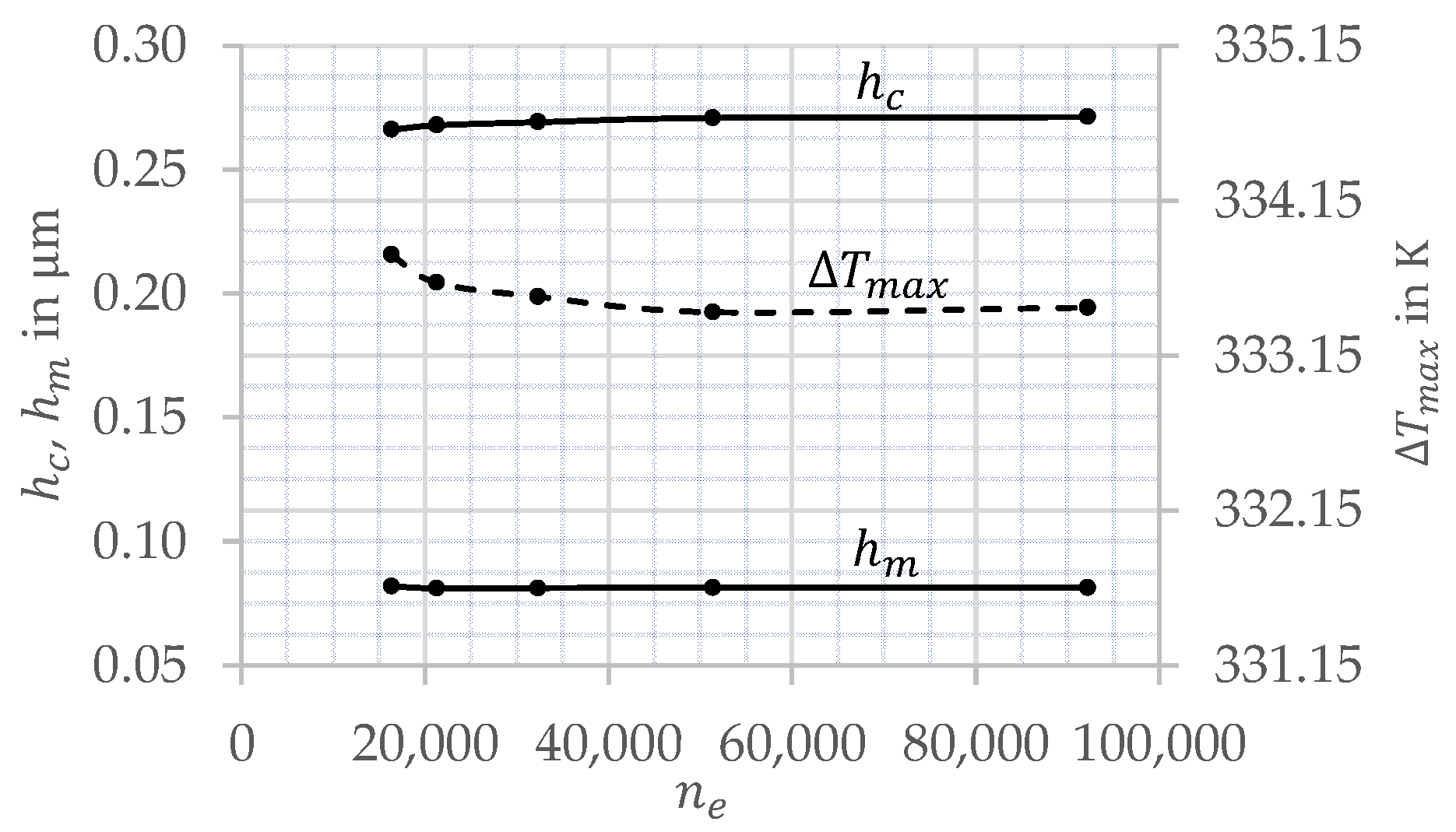
The sensitivity of the solution to mesh size was tested by applying five different mesh resolutions and comparing the results (see Table 4 and Figure 3). A slender contact for which , , and was simulated as test case. The geometric, material and oil properties are given in Section 2.1.
The film thickness and temperature results in Figure 3 reveal a small influence of mesh size on the TEHL solution, which converges with an increasing number of elements. A fine mesh with a total of elements was chosen for all simulations. The corresponding pressure, film thickness and temperature distributions of the slender contact test case are shown in Figure 4.
3. Results and Discussion
This section presents and discusses the experimental and numerical results for the slender EHL contacts. For the purpose of classification, the same set of experimental and numerical results are provided for circular EHL contacts. Operating conditions, geometric and material properties are listed in Table 1, Table 2 and Table 3.
3.1. Film Thickness
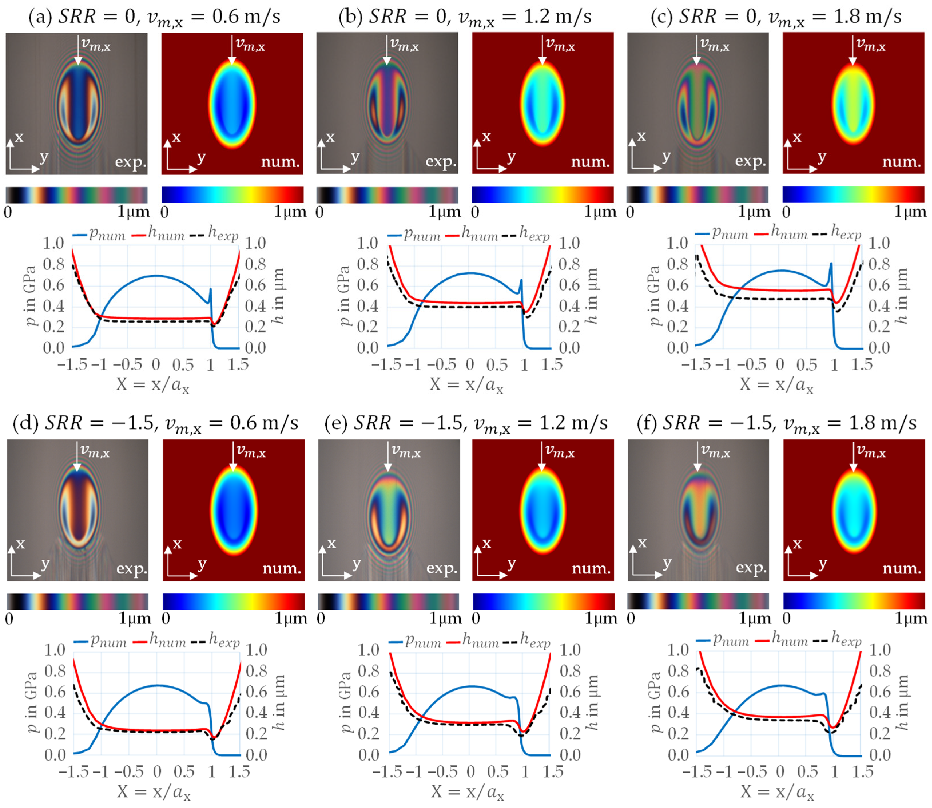
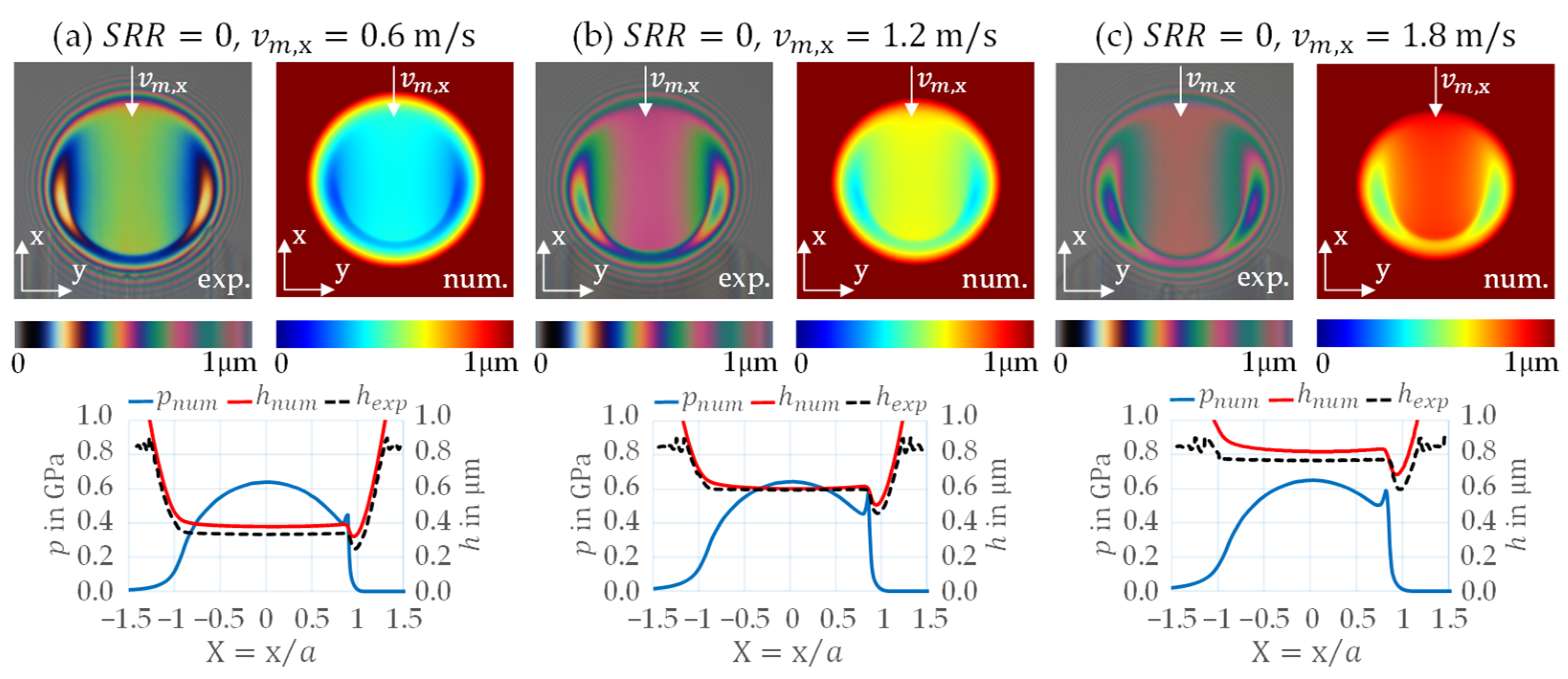
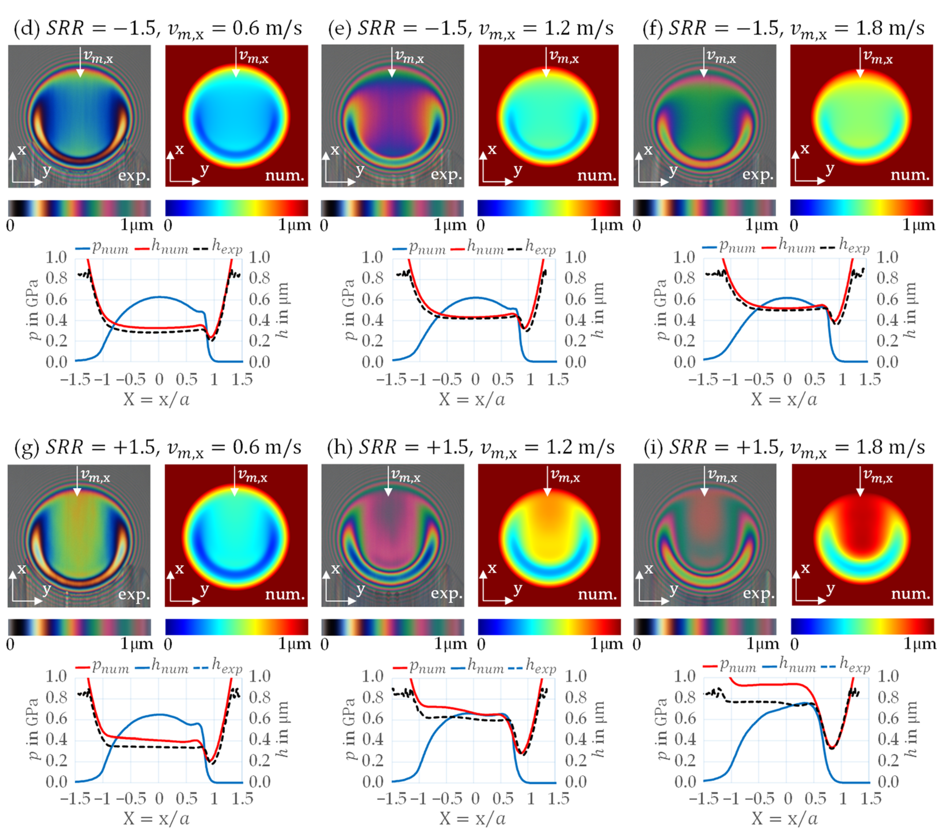
Figure 5 and Figure 6 show measured and calculated film thickness interferograms, together with the derived film thickness and , and calculated pressure profiles in gap length direction for the entrainment speeds and slide-to-roll ratios . Figure 5 refers to slender EHL contacts and Figure 6 to circular ones. In the graphs showing film thickness and pressure profiles, -axis is normalized by the semi-major Hertzian contact length for the slender contact and Hertzian half-width for the circular contact. Hence, the positions and represent the outer borders of the Hertzian contact area for both types of contact.
At , the film thickness interferograms and profiles for the slender EHL contact in Figure 5a–c show that the film thickness in the central region is flat and has a “U-shape”. Also, it can be seen that it reaches its minima in the side lobes regardless of the applied speed. The overall increase in film thickness with increasing entrainment speed is evident. Pressure distributions are characterized by a second pressure maximum. The described features and trends are typical for pure rolling conditions. They are also seen in the circular contact (Figure 6a–c) with the difference that the film thickness in the central region is semi-circular rather than U-shaped. Overall, at the film thickness in the circular contact is approx. higher than in the slender contact.
At , at which the upper glass disk moves more slowly than the lower steel roller, different trends of the film thickness are visible than at . For all three entrainment speeds, the film thickness of the slender EHL contacts at in Figure 5d–f is lower than at . This is a consequence of oil shearing and consequent temperature generation inside the oil film at . On the other hand, the film thickness features, in terms of the shape in the central region and the location of the minima, are similar to those seen at for the all three entrainment speeds. The second pressure maximum is less pronounced than at . The conclusions that can be drawn for negative in the circular EHL contact case in Figure 6d–f are almost the same; the film thickness is approx. higher in the circular contact case.
At , where the upper glass disk moves faster than the lower steel roller, the shape of the film thickness changes, as does its dependence on the entrainment speed. The film thickness inteferogram for the lowest entrainment speed of (Figure 5g) shows that the film thickness is mostly flat with a U-shape in the central region and minima located in the side lobes. These features of the film thickness closely resemble those visible at and . However, at higher entrainment speeds of and , the two side minima merge in the contact outlet region, as shown by the interferograms in Figure 5h–i. It can also be seen here that the film thickness is no longer flat in the central region of the contact, but decreases over the gap length, taking on a V-shape in the central region. Because of this, the film thickness in the central region increases with increasing entrainment speed, while the film thickness at the constriction remains almost constant. The pressure profiles display changes, and their level increases with increasing entrainment speed. Also, the second pressure maximum is less visible than at and . The slender EHL contact in Figure 5d–f shows a lower film thickness in the central region at than at and a higher film thickness at the constriction at than at , regardless of the entrainment speed. This indicates that the oil quantity causing a higher film thickness in the central region at has to leave the contact through the sides for the film thickness to be lower at the same . Furthermore, the pressure profile changes, and its level is lower for compared to .
The features and trends occurring in the corresponding circular EHL contact (Figure 6g–i) are similar to those of the slender EHL contact at . However, the film thickness does not decrease along the gap length direction but increases in the central region and shows a higher dependence on the entrainment speed at the constriction than in the slender contact. Additionally, the film thickness is approx. greater in the circular contact than in the slender one. Furthermore, dimples are more pronounced in the circular contact.
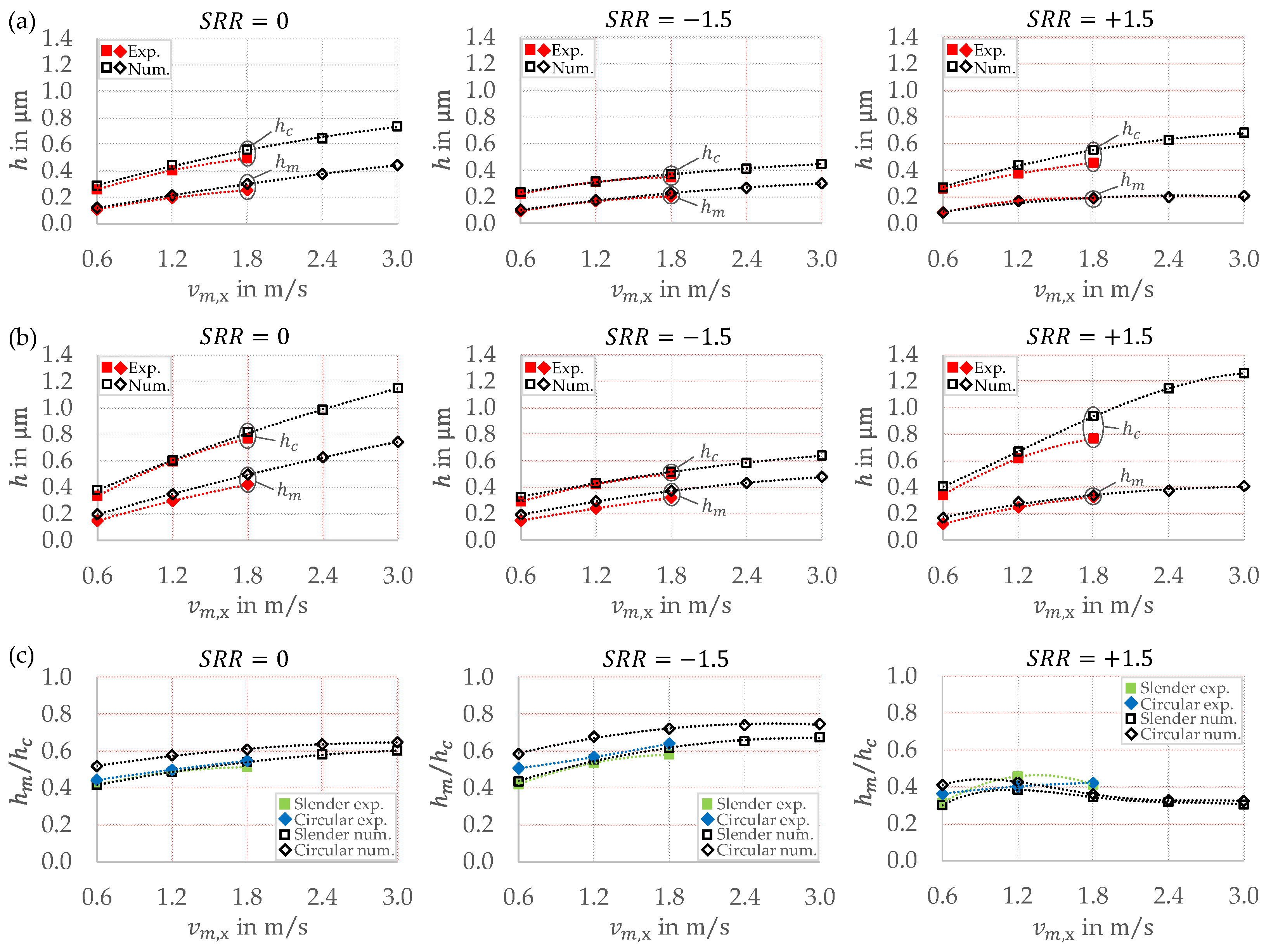
The results shown in Figure 5 and Figure 6 are further evaluated in terms of the minimum and central film thickness. In most cases, the minimum film thickness occurs in the side lobes of the EHL contact. Only at and entrainment speeds does occur along the central profile in gap length direction. The central film thickness is defined as . Figure 7 shows the values of and as well as their ratio for the slender and circular EHL contact for all entrainment speeds and slide-to-roll ratios . The entrainment speed range is extended by the numerical results for , which was not investigated experimentally. A comparison of different values for the slender EHL contact (Figure 7a) confirms that both and are lower for compared to . For , is very similar and significantly lower compared to . For the circular EHL contact (Figure 7b), the film thickness is generally higher, with very comparable trends. This is confirmed by the ratio of to in Figure 7c. Note that the ratios are very similar when comparing and , but different for . This applies to the slender and circular EHL contact under consideration and can be explained by analyzing the contact temperature and viscosity for in Section 3.2.
In general, the experimental and numerical results for the slender and circular EHL contacts are in good agreement. Slightly higher differences between the numerical and experimental results are seen at positive and higher entrainment speeds, especially for the circular contact. All things considered, the differences do not affect the general trends or conclusions.
3.2. Temperature, Viscosity and Velocity
The results in Section 3.1 show that for , with the glass disk moving faster than the counter steel body, increasing has almost no effect on . This can be understood by analyzing the contact temperature and viscosity distributions. Only the results for the slender EHL contact are analyzed, as the circular EHL contact has very similar characteristics.
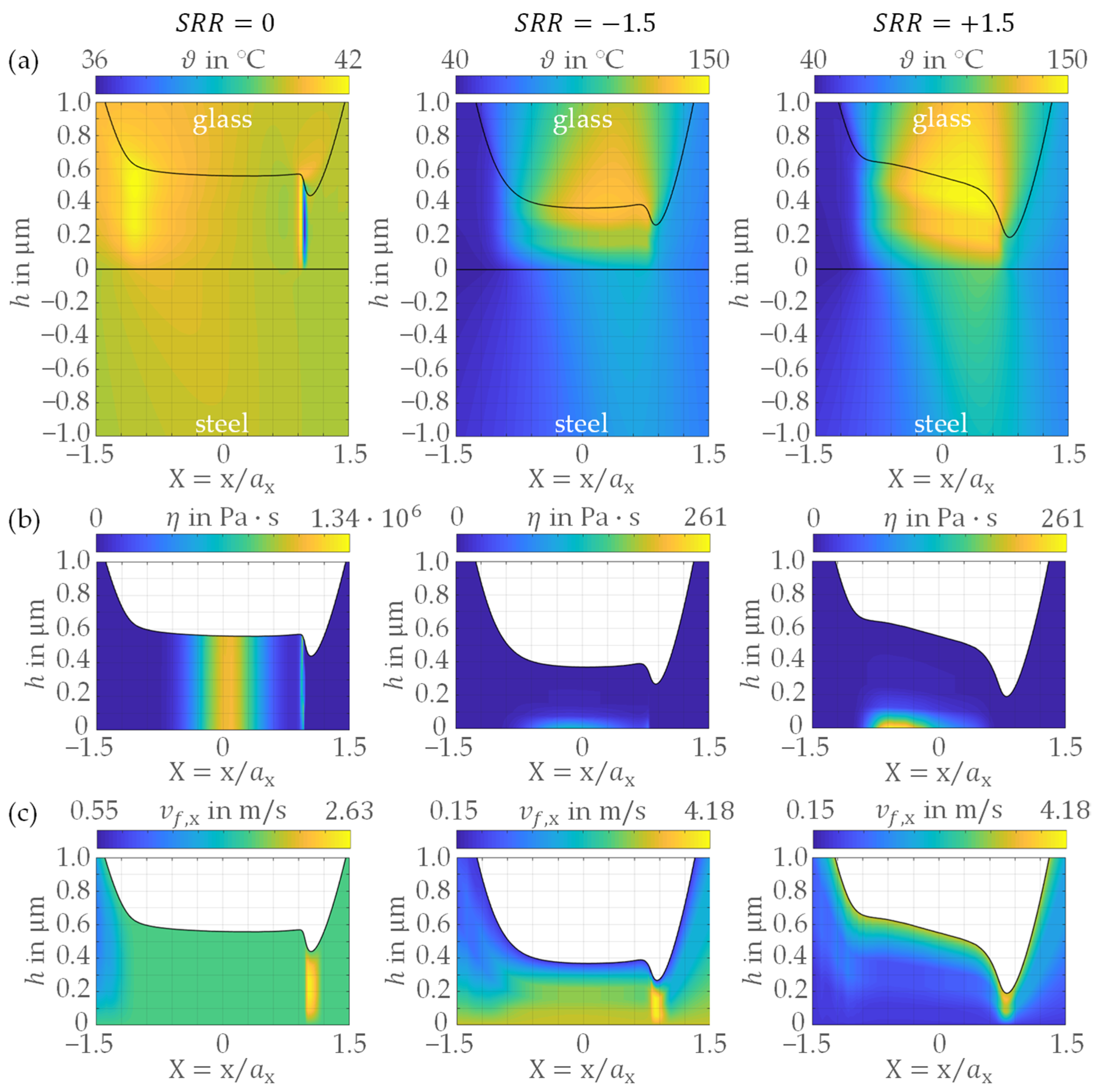
Figure 8 shows the calculated temperature (), viscosity () and velocity () distributions across the oil film for and different for the slender EHL contact. Here, -axis is normalized by the semi-major Hertzian contact length . Please also note that one color scale is used for and another for . This allows a qualitative comparison to be made between and , while the results at serve as a reference with negligible thermal effects.
Since glass has a much lower thermal effusivity than steel (see Table 2), the glass surface has a higher temperature than the steel surface for conditions where (see Figure 8a, ). This results in the oil being more viscous in the vicinity of the steel surface (see Figure 8b, ), creating a so-called viscosity wedge [15,31]. When the steel surface moves faster than the glass surface (), the viscosity wedge is weak. The flow is less constricted, and the oil moves through the contact at higher speed (see Figure 8c, ), resulting in a lower central film thickness. When the steel surface moves more slowly than the glass surface (), the viscous oil moves more slowly through the contact (see Figure 8c, ). This is due to the strong viscosity wedge on the steel surface that constricts the oil flow in the entrainment direction. It induces additional fluid pressure (see Figure 5) and increases the film thickness in the central region. Hence, the different ratio of to when comparing and in Figure 7c is due to the unequal temperature distributions in the gap height direction caused by the different thermal effusivities of glass and steel.
Comparing the slender and circular EHL contacts, it can be seen that the film thickness shape in the central region differs significantly at (see Figure 5g–i and Figure 6g–i). For the slender EHL contact, there is a decreasing trend along the gap length, and it displays a V-shape. This characteristic is discussed in the comparison of the slender and circular EHL contacts in Section 3.3.
3.3. Side Flow
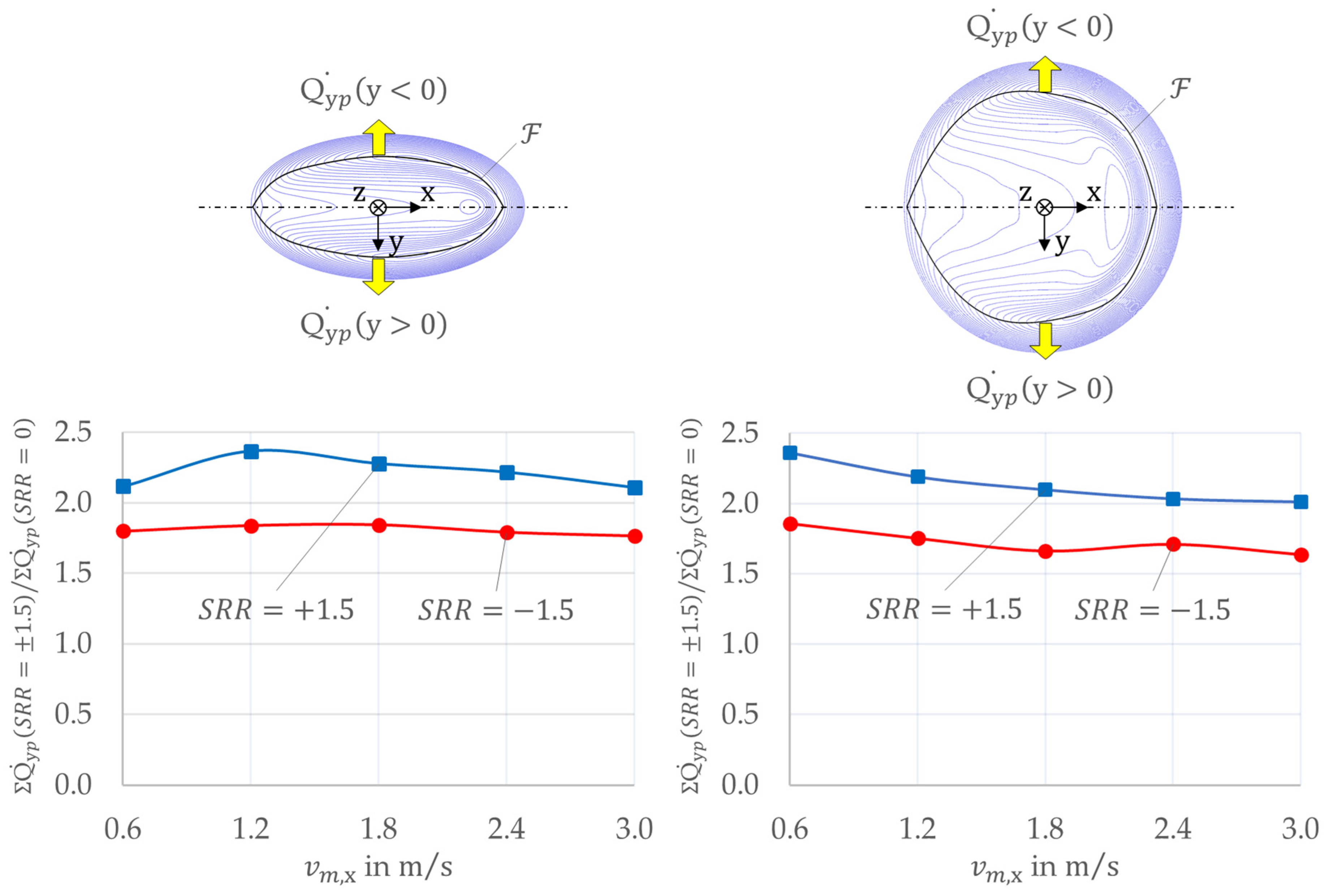
The side flow in the EHL contacts can be quantified in terms of the mass flow rate crossing a frontier in y-direction: . In this study, the frontier is defined within the lubricated contact at positions where the film thickness minima form an envelope. It is obtained by reading the minima in the --planes for different positions. The total side flow is defined as .
Figure 9 shows the evaluated side flow for the slender and circular EHL contact for all calculated entrainment speeds in a relative manner. Thereby, and is related to , as it constitutes a reference with negligible thermal effects. The results show that over the considered range of entrainment speeds, the side flow ratio is significantly higher at than at , and higher at than at . Since side flow is governed by the pressure driven flow in -direction (see in Equation (4)), high side flow occurs in cases where the pressure gradient is high. For , the strong viscosity wedge (see Section 3.2) results in higher fluid pressure (see Section 3.1) and gradients. For , the effect is present, but less pronounced. For , no viscosity wedge occurs.
The main reason for decreasing trend along the gap length direction for the slender EHL contact at (see Figure 5g–i) is the strong viscosity wedge, which constricts the oil flow. Its diversion through the contact sides leaves less oil for maintaining the oil film in the central region. Consequently, the film thickness steadily decreases along the gap length. Although a strong viscosity wedge also exists in the circular EHL contact at , the wider contact area here limits the side leakage. This in turn results in more oil being available for maintaining the oil film than in the slender EHL contact. However, as the oil is still forced to pass over the viscosity wedge in the circular contact, additional pressure inside the oil is induced, which causes dimples to occur in the film thickness.
4. Conclusions
This study analyzed a slender EHL contact by numerical and experimental means with a focus on thermal effects at high sliding. For classification, a circular EHL contact was considered under the same operating conditions. The main conclusions can be summed up as follows:
- The film thickness is lower for slender EHL contacts than for circular ones, considering the same Hertzian pressure.
- The different thermal effusivities of glass and steel result in a viscosity wedge, which is particularly pronounced at high positive sliding with the glass disk moving faster.
- A strong viscosity wedge diverts the oil flow to the contact sides and limits the amount of oil maintaining the oil film in the central region.
- At high positive sliding, a continuous decrease in film thickness is observed in the gap length direction of the slender EHL contact.
- At high positive sliding, the influence of entrainment speed on minimum film thickness is almost negligible, especially for slender contacts.
- To support EHL film formation in slender EHL contacts at higher sliding, the solid body made of the material with higher thermal effusivity has to move faster.
Worm gears are machine elements characterized by slender EHL contacts, high sliding and different materials, e.g., bronze and steel. The ellipticity ratios are typically lower than those considered in this study. Slender EHL contacts of worm gears will be the focus of further investigations.
Author Contributions
Conceptualization, M.T., T.L. and R.L.; methodology, M.T., T.L. and R.L.; software, M.T.; validation, M.T.; formal analysis, M.T.; investigation, M.T.; resources, M.T. and T.L.; data curation, M.T.; writing—original draft preparation, M.T. and T.L.; writing—review and editing, M.T., T.L. and R.L.; visualization, M.T.; supervision, T.L. and R.L.; project administration, T.L.; funding acquisition, M.T. and T.L. All authors have read and agreed to the published version of the manuscript.
Funding
This work was financially supported by German Academic Exchange Service (DAAD).
Acknowledgments
The authors gratefully acknowledge Karsten Stahl for providing the opportunity to conduct the research at FZG and Andreas Schwarz for aiding the experimental and numerical investigations.
Conflicts of Interest
The authors declare no conflict of interest. The funders had no role in the design of the study; in the collection, analyses, or interpretation of data; in the writing of the manuscript, or in the decision to publish the results.
Nomenclature
| Latin symbols | ||
| Coefficients of the lubricant heat capacity model | ||
| Coefficients of the lubricant Vogel temperature model | ||
| Hertzian half-width, circular contact | ||
| Semi-major Hertzian contact length, slender contact | ||
| Semi-minor Hertzian contact length, slender contact | ||
| Compliance matrix | ||
| Specific heat capacity | ||
| Coefficients of the lubricant Bode density model | ||
| Thermal effusivity | ||
| Pressure coefficients of the lubricant thermal conductivity model | ||
| Young’s Modulus | ||
| Normal force | ||
| Film thickness | ||
| Central film thickness | ||
| Minimum film thickness | ||
| Dimensionless film thickness | ||
| Dimensionless constant parameter of the film thickness equation | ||
| Ellipticity ratio | ||
| Number of mesh elements in domain | ||
| Number of mesh layers in gap height direction in domain | ||
| Number of mesh elements in domain | ||
| Number of mesh elements in domain | ||
| Number of mesh elements in domain | ||
| Number of mesh elements in domain | ||
| Total number of mesh elements | ||
| Hydrodynamic pressure | ||
| Dimensionless hydrodynamic pressure | ||
| Hertzian pressure | ||
| Mass flow rate crossing the frontier in y-direction | ||
| Coefficient of the Roelands’ equation | ||
| Peclet number for the energy equation | ||
| Radii of curvature in x- and y-direction | ||
| Slide-to-roll ratio | ||
| Temperature | ||
| Maximum temperature | ||
| Bulk temperature | ||
| Displacement vector | ||
| Sliding speed in x-direction. | ||
| Entrainment speed in x-direction | ||
| Sum speed in x-direction | ||
| Speed of the counter steel body | ||
| Speed of the glass disk | ||
| Coordinates | ||
| Dimensionless coordinates | ||
| Greek symbols | ||
| Pressure viscosity coefficient | ||
| Coefficient of the lubricant Bode density model | ||
| Deformation of the equivalent body | ||
| Dimensionless deformation of the equivalent body | ||
| Strain tensor | ||
| Shear rate in x-direction | ||
| Temperature | ||
| Oil temperature | ||
| Dynamic viscosity | ||
| Dimensionless dynamic viscosity | ||
| Dynamic viscosity of the lubricant at and atmospheric pressure | ||
| Thermal conductivity | ||
| Thermal conductivity of the lubricant at and atmospheric pressure | ||
| Poisson’s ratio | ||
| Density | ||
| Dimensionless density | ||
| Fluid density at and atmospheric pressure | ||
| Coefficient of the lubricant Bode density model | ||
| Stress tensor of the equivalent body | ||
| Total mass flow rate crossing the frontier in y-direction | ||
| Shear stress | ||
| Eyring shear stress | ||
| Dimensionless shear stress components in the x- and y-directions over the domain | ||
| Special symbols | ||
| Frontier used for the side flow analysis | ||
| Indices | ||
| Lower solid body (counter steel body) | ||
| Upper solid body (glass disk) | ||
| Fluid |
References
- Sharif, K.J.; Kong, S.; Evans, H.P.; Snidle, R.W. Contact and elastohydrodynamic analysis of worm gears Part 2: Results. Proc. Inst. Mech. Eng. Part C J. Mech. Eng. Sci. 2001, 215, 831–846. [Google Scholar] [CrossRef] [Green Version]
- Venner, C.H.; Lubrecht, A. Revisiting film thickness in slender elastohydrodynamically lubricated contacts. Proc. Inst. Mech. Eng. Part C 2010, 224, 2549–2558. [Google Scholar] [CrossRef]
- Wolf, M.; Solovyev, S.; Fatemi, A. Film thickness in elastohydrodynamically lubricated slender elliptic contacts: Part I—Numerical studies of central film thickness. Proc. Inst. Mech. Eng. Part J J. Eng. Tribol. 2022, 236, 1043–1055. [Google Scholar] [CrossRef]
- Mostofi, A.; Gohar, R. Oil Film Thickness and Pressure Distribution in Elastohydrodynamic Point Contacts. J. Mech. Eng. Sci. 1982, 24, 173–182. [Google Scholar] [CrossRef]
- Evans, H.P.; Snidle, R.W. Analysis of Elastohydrodynamic Lubrication of Elliptical Contacts with Rolling along the Major Axis. Proc. Inst. Mech. Eng. Part C J. Mech. Eng. Sci. 1983, 197, 209–211. [Google Scholar] [CrossRef]
- Gohar, R.; Cameron, A. Optical Measurement of Oil Film Thickness under Elasto-hydrodynamic Lubrication. Nature 1963, 200, 458–459. [Google Scholar] [CrossRef]
- Thorp, N.; Gohar, R. Oil Film Thickness and Shape for a Ball Sliding in a Grooved Raceway. J. Lubr. Technol. 1972, 94, 199–208. [Google Scholar] [CrossRef]
- Chittenden, R.J.; Dowson, D.; Dunn, J.F.; Taylor, C.M. A theoretical analysis of the isothermal elastohydrodynamic lubrication of concentrated contacts. I. Direction of lubricant entrainment coincident with the major axis of the Hertzian contact ellipse. Proc. R. Soc. London 1985, 397, 245–269. [Google Scholar] [CrossRef]
- Wheeler, J.; Vergne, P.; Fillot, N.; Philippon, D. On the relevance of analytical film thickness EHD equations for isothermal point contacts: Qualitative or quantitative predictions? Friction 2016, 4, 369–379. [Google Scholar] [CrossRef] [Green Version]
- Marian, M.; Bartz, M.; Wartzack, S.; Rosenkranz, A. Non-Dimensional Groups, Film Thickness Equations and Correction Factors for Elastohydrodynamic Lubrication: A Review. Lubricants 2020, 8, 95. [Google Scholar] [CrossRef]
- Wheeler, J.D.; Fillot, N.; Vergne, P.; Philippon, D.; Morales-Espejel, G. On the crucial role of ellipticity on elastohydrodynamic film thickness and friction. Proc. Inst. Mech. Eng. Part J J. Eng. Tribol. 2016, 230, 1503–1515. [Google Scholar] [CrossRef]
- Wolf, M.; Sperka, P.; Fryza, J.; Fatemi, A. Film Thickness in Elastohydrodynamically Lubricated Slender Elliptic Contacts: Part II—Experimental Validation and Minimum Film Thickness. Proc. Inst. Mech. Eng. Part J J. Eng. Tribol. 2022. [Google Scholar] [CrossRef]
- Kaneta, M.; Nishikawa, H. Formation of dimples in elliptical EHL contacts. In Thinning Films and Tribological Interfaces, Proceedings of the 26th Leeds-Lyon Symposium on Tribology, Leeds, UK, 14–17 September 1999; Dowson, D., Priest, M., Taylor, C.M., Ehret, P., Childs, T.H.C., Dalmaz, G., Lubrecht, A., Berthier, Y., Flamand, L., Georges, J.M., Eds.; Elsevier Science B. V.: Amsterdam, The Netherlands, 2000; pp. 599–607. [Google Scholar] [CrossRef]
- Kaneta, M.; Kawashima, R.; Masuda, S.; Nishikawa, H.; Yang, P.; Wang, J. Thermal Effects on the Film Thickness in Elliptic EHL Contacts with Entrainment Along the Major Contact Axis. ASME J. Tribol. 2001, 124, 420–427. [Google Scholar] [CrossRef]
- Kaneta, M.; Yang, P. Effects of the thermal conductivity of contact materials on elastohydrodynamic lubrication characteristics. Proc. Inst. Mech. Eng. Part C J. Mech. Eng. Sci. 2010, 224, 2577–2587. [Google Scholar] [CrossRef]
- Yilmaz, M.; Mirza, M.; Lohner, T.; Stahl, K. Superlubricity in EHL Contacts with Water-Containing Gear Fluids. Lubricants 2019, 7, 46. [Google Scholar] [CrossRef]
- Hartl, M.; Křupka, I.; Liška, M. Differential colorimetry: Tool for evaluation of chromatic interference patterns. Opt. Eng. 1997, 36, 2384–2391. [Google Scholar] [CrossRef]
- Molimard, J.; Querry, M.; Vergne, P.; Krupka, I.; Hartl, M.; Poliscuk, R.; Liska, M. Differential Colorimetry: A tool for the analysis of fluid film lubrication. Mec. Ind. 2002, 3, 571–581. [Google Scholar] [CrossRef]
- Ziegltrum, A.; Lohner, T.; Stahl, K. TEHL Simulation on the Influence of Lubricants on the Frictional Losses of DLC Coated Gears. Lubricants 2018, 6, 17. [Google Scholar] [CrossRef] [Green Version]
- Habchi, W.; Bair, S. The role of the thermal conductivity of steel in quantitative elastohydrodynamic friction. Tribol. Int. 2019, 142, 105970. [Google Scholar] [CrossRef]
- Habchi, W. Finite Element Modeling of Elastohydrodynamic Lubrication Problems; John Wiley & Sons Incorporated: Newark, NJ, USA, 2018. [Google Scholar]
- Nijenbanning, G.; Venner, C.H.; Moes, H. Film thickness in elastohydrodynamically lubricated elliptic contacts. Wear 1994, 176, 217–229. [Google Scholar] [CrossRef] [Green Version]
- Vogel, H. Principle of temperature dependency of viscosity of fluids. Z. Phys. 1921, 22, 645–647. [Google Scholar]
- Fulcher, G.S. Analysis of Recent Measurements of the Viscosity of Glasses II. J. Am. Ceram. Soc. 1925, 8, 789–794. [Google Scholar] [CrossRef]
- Tammann, G.; Hesse, W. Die Abhängigkeit der Viskosität von der Temperatur bei unterkühlten Flüssigkeiten [Temperature dependency of viscosity of undercooled liquids]. Z. Für Anorg. Und Allg. Chem. 1926, 156, 245–247. [Google Scholar] [CrossRef]
- Roelands, C.J.A. Correlation Aspects of the Viscosity-Temperature Relationship of Lubricating Oil. Ph.D. Thesis, Technische Hogeschool Delft, Delft, The Netherlands, 1966. [Google Scholar]
- Eyring, H. Viscosity, Plasticity, and Diffusion as Examples of Absolute Reaction Rates. J. Chem. Phys. 1936, 4, 283–291. [Google Scholar] [CrossRef]
- Bode, B. Modell zur Beschreibung des Fließverhaltens von Flüssigkeiten unter hohem Druck [Model for describing the rheological behaviour of liquids under high pressure]. Tribol. Schmier. 1989, 36, 182–189. [Google Scholar]
- Larsson, E.; Andersson, O. Lubricant thermal conductivity and heat capacity under high pressure. Proc. Inst. Mech. Eng. Part J J. Eng. Tribol. 2000, 214, 337–342. [Google Scholar] [CrossRef]
- Ziegltrum, A.; Maier, E.; Lohner, T.; Stahl, K.A. Numerical Study on Thermal Elastohydrodynamic Lubrication of Coated Polymers. Tribol. Lett. 2020, 68, 71. [Google Scholar] [CrossRef]
- Omasta, M.; Adam, J.; Sperka, P.; Krupka, I.; Hartl, M. On the Temperature and Lubricant Film Thickness Distribution in EHL Contacts with Arbitrary Entrainment. LubricanIts 2018, 6, 101. [Google Scholar] [CrossRef] [Green Version]
Figure 1.
Mechanical layout of the used optical EHL tribometer based on [16].
Figure 1.
Mechanical layout of the used optical EHL tribometer based on [16].

Figure 2.
FEM model of the TEHL point contact problem. (a) Geometry of the 3D computation domains; (b) Discretized domains; (c) Discretized oil film domain.
Figure 2.
FEM model of the TEHL point contact problem. (a) Geometry of the 3D computation domains; (b) Discretized domains; (c) Discretized oil film domain.

Figure 3.
Film thickness and temperature convergence with respect to the mesh size.

Figure 4.
Solution of a slender EHL contact test case with fine mesh. (a) Pressure distribution; (b) Film thickness distribution; (c) Temperature distribution.
Figure 4.
Solution of a slender EHL contact test case with fine mesh. (a) Pressure distribution; (b) Film thickness distribution; (c) Temperature distribution.

Figure 5.
Experimental and numerical results for the slender EHL contact with different slide-to-roll ratios and entrainment speeds (subfigures (a–i)): Measured and calculated interferograms (top), derived film thickness profiles and , and calculated presure profiles in gap length direction (bottom).


Figure 6.
Experimental and numerical results for the circular EHL contact with different slide-to-roll ratios and entrainment speeds (subfigures (a–i)): Measured and calculated interferograms (top), derived film thickness profiles and , and calculated pressure profiles in gap length direction (bottom).


Figure 7.
Experimental and numerical results for and over entrainment speed for (left), (middle) and (right). (a) Slender EHL contact; (b) Circular EHL contact; (c) Ratio of to for slender and circular EHL contact.
Figure 7.
Experimental and numerical results for and over entrainment speed for (left), (middle) and (right). (a) Slender EHL contact; (b) Circular EHL contact; (c) Ratio of to for slender and circular EHL contact.

Figure 8.
Numerical results for temperature (a), viscosity (b) and velocity (c) distributions in the slender EHL contact at and different .
Figure 8.
Numerical results for temperature (a), viscosity (b) and velocity (c) distributions in the slender EHL contact at and different .

Figure 9.
Schematic representation of the frontier used for the side flow analysis (top). Variation of side flow ratio for different and in the slender (bottom left) and circular EHL contact (bottom right).
Figure 9.
Schematic representation of the frontier used for the side flow analysis (top). Variation of side flow ratio for different and in the slender (bottom left) and circular EHL contact (bottom right).


Table 1.
Operating conditions.
| Slender Contact | Circular Contact | ||
|---|---|---|---|
Table 2.
Solid material properties.
| Steel | Glass | ||
|---|---|---|---|
| [20] | 1.1 | ||
Table 3.
Properties of MIN100 [19].
Table 3.
Properties of MIN100 [19].
Table 4.
Number of elements per each individual computation domain.
| Mesh Case | |||||||
|---|---|---|---|---|---|---|---|
| Extra coarse | 1301 | 3 | 3903 | 671 | 5891 | 5826 | 16,291 |
| Coarse | 1521 | 3 | 4563 | 2489 | 7143 | 7028 | 21,233 |
| Normal | 1866 | 4 | 7464 | 7289 | 8734 | 8792 | 32,279 |
| Fine | 2658 | 5 | 13,290 | 13,385 | 12,345 | 12,336 | 51,356 |
| Extra fine | 2658 | 10 | 26,580 | 40,958 | 12,345 | 12,336 | 92,219 |
1 Total number of mesh elements is calculated as: .
Publisher’s Note: MDPI stays neutral with regard to jurisdictional claims in published maps and institutional affiliations. |
© 2022 by the authors. Licensee MDPI, Basel, Switzerland. This article is an open access article distributed under the terms and conditions of the Creative Commons Attribution (CC BY) license (https://creativecommons.org/licenses/by/4.0/).
Share and Cite
MDPI and ACS Style
Tošić, M.; Larsson, R.; Lohner, T. Thermal Effects in Slender EHL Contacts. Lubricants 2022, 10, 89. https://0-doi-org.brum.beds.ac.uk/10.3390/lubricants10050089
AMA Style
Tošić M, Larsson R, Lohner T. Thermal Effects in Slender EHL Contacts. Lubricants. 2022; 10(5):89. https://0-doi-org.brum.beds.ac.uk/10.3390/lubricants10050089
Chicago/Turabian StyleTošić, Marko, Roland Larsson, and Thomas Lohner. 2022. "Thermal Effects in Slender EHL Contacts" Lubricants 10, no. 5: 89. https://0-doi-org.brum.beds.ac.uk/10.3390/lubricants10050089
Note that from the first issue of 2016, this journal uses article numbers instead of page numbers. See further details here.