Influence of Bionic Circular Groove Blade Surface on Wear Performance
by
 ,
,
Longbiao Ma
1,2, 
Yunqing Gu
1,2,*,
Ke Xia
3,
Chengqi Mou
4,
Jiegang Mou
1,2,*,
Denghao Wu
1,2 and
Muhan Yan
1,2 1
College of Metrology & Measurement Engineering, China Jiliang University, Hangzhou 310018, China
2
Zhejiang Engineering Research Center of Fluid Equipment & Measurement and Control Technology, China Jiliang University, Hangzhou 310018, China
3
College of Mechanical Engineering, Zhejiang University of Technology, Hangzhou 310023, China
4
College of Energy Engineering, Zhejiang University, Hangzhou 310027, China
*
Authors to whom correspondence should be addressed.
Lubricants 2022, 10(5), 101; https://0-doi-org.brum.beds.ac.uk/10.3390/lubricants10050101
Submission received: 11 April 2022
/
Revised: 7 May 2022
/
Accepted: 12 May 2022
/
Published: 19 May 2022
(This article belongs to the Special Issue Friction and Wear in Machine Design)
Abstract
:In order to improve the anti-wear performance of a double-vane self-priming centrifugal pump during two-phase flow transfer, the construction of a streamline groove structure at the outlet end of the suction side of the vane, based on the bionic principle, is proposed. Different pump characteristics are analysed to investigate the effect of different bionic groove spacing on the resistance to particle wear and the mechanism of improvement of the bionic grooves. The results show that the effect of the bionic blades on the hydraulic characteristics of the pump is within the allowable error (±1.4%). The circular groove structure with different spacing produces a difference in the pressure distribution on the blade. At the same particle concentration, with the increase in the groove spacing distance, the average wear of the blades first decreases and then increases; the average wear rate at the spacing of 7 mm is the smallest. At a particle concentration of 90 kg/m3, the average wear rate at a groove spacing of 7 mm is ~0.63 × 10⁻⁴ kg/s∙m2, and the wear area is mainly found in the middle of the blade. The reason why the bionic blade improves the anti-wear performance of the pump is due to the reverse vortex zone in the groove, which changes the particle trajectory and collision frequency. The bionic grooves with a diameter of 2 mm and a spacing of 7 mm significantly reduce the average wear rate of the pump at different particle concentrations, while maintaining hydraulic performance.
1. Introduction
Pumps are hydraulic machines that are commonly used to convert mechanical energy into energy for the transport of liquids [1]. Not only can single-phase flows be transported, but two-phase flows containing solid particles can also be transported. However, during the transport of solid–liquid two-phase flows, given that solid particles are generally present as discrete phases in the internal flow channel of the pump, there is a velocity difference between the discrete and continuous phases [2]. As a result, collisions and friction occur between the particles and the walls of the flowing parts, directly affecting the hydraulic performance and service life of the pump [3,4]. The two-vane self-priming centrifugal pump is mainly used for municipal and industrial sewage containing solid-phase impurities, such as suspended matter, sand, gravel, and mud [5]. In order to avoid blockage of the sewage pump by solids in suspension, the impeller adopts a non-clogging design method with a low number of blades, reducing damage to the overflow components by solid phase impurities during transport. However, with the growth of the population and the advancement of urbanization and industrialization, the volume of sewage discharged by cities and industries is increasing, and the performance of sewage pumps is becoming more demanding. Without affecting the hydraulic performance of the two-vane self-priming centrifugal pump, improving the wear of the sewage pump during transportation and improving the continuous operation of the pump have important research significance.
Current methods for improving wear in pumps are divided between surface treatment techniques [6,7] and research into anti-wear materials [8,9,10]. However, both methods have obvious advantages and disadvantages and are not well suited to improving the wear performance of pumps in terms of production costs, material processing, and service life. After a long period of biological evolution and the survival of the fittest, current organisms are well adapted to their environment, both in terms of body structure and functional principles. Biomimetics is an interdisciplinary research direction that improves wear resistance, noise reduction, cavitation resistance, drag reduction, and other properties based on the superior structure and function of organisms. The arrangement of the circular, non-smooth surface structure at the blade of the centrifugal pump can increase the turbulent energy at the suction surface of the blade near the wall, which has a better suppression effect on cavitation [11]. Very recently, Ma et al. [12] arranged the bionic non-smooth structure at the blade of the centrifugal pump, and noted that the bionic circular blade had the best wear resistance compared with the smooth blade and other non-smooth structure blades. Based on the surface characteristics of sharks, Dai et al. [13] established a centrifugal pump model with V-groove surface blades, which could increase the hydraulic efficiency of the centrifugal pump by 2.06% and decrease the total sound pressure level by 2.68%. Currently, bionics are widely used in improving fluid mechanical performance [14], but improving particle wear in pumps based on bionic principles is less common.
As one of the marine anti-abrasive organisms [15], the shell surface of the Scapharca subcrenata has a ribbed structure of 30 to 35 ribs, with grooves formed between adjacent ribs. The surface groove structure creates vortex and buffering effects that reduce the abrasive strength and effective friction between the particles and the shell surface. Thus, the bionic structure is arranged in the most prone wear area of the centrifugal pump blade by imitating the wear-resistant and anti-wear biological surface structure of this organism. The impact of bionic structural parameters on the external characteristics, pressure field distribution, and anti-wear performance of the double-vane pump under different particle concentrations was investigated, exploring the optimum groove spacing to improve the anti-wear effect of solid–liquid two-phase centrifugal pumps without affecting their hydraulic performance. At the end, the mechanism of improving wear resistance by bionic groove structure was analyzed. The use of bionics to improve the anti-abrasive properties of hydraulic machinery not only extends the service life of pumps in solid–liquid transport, but also provides ideas and the theoretical foundation for anti-abrasive wear of machinery.
2. Feature Extraction and Numerical Simulation
2.1. Feature Surface Extraction
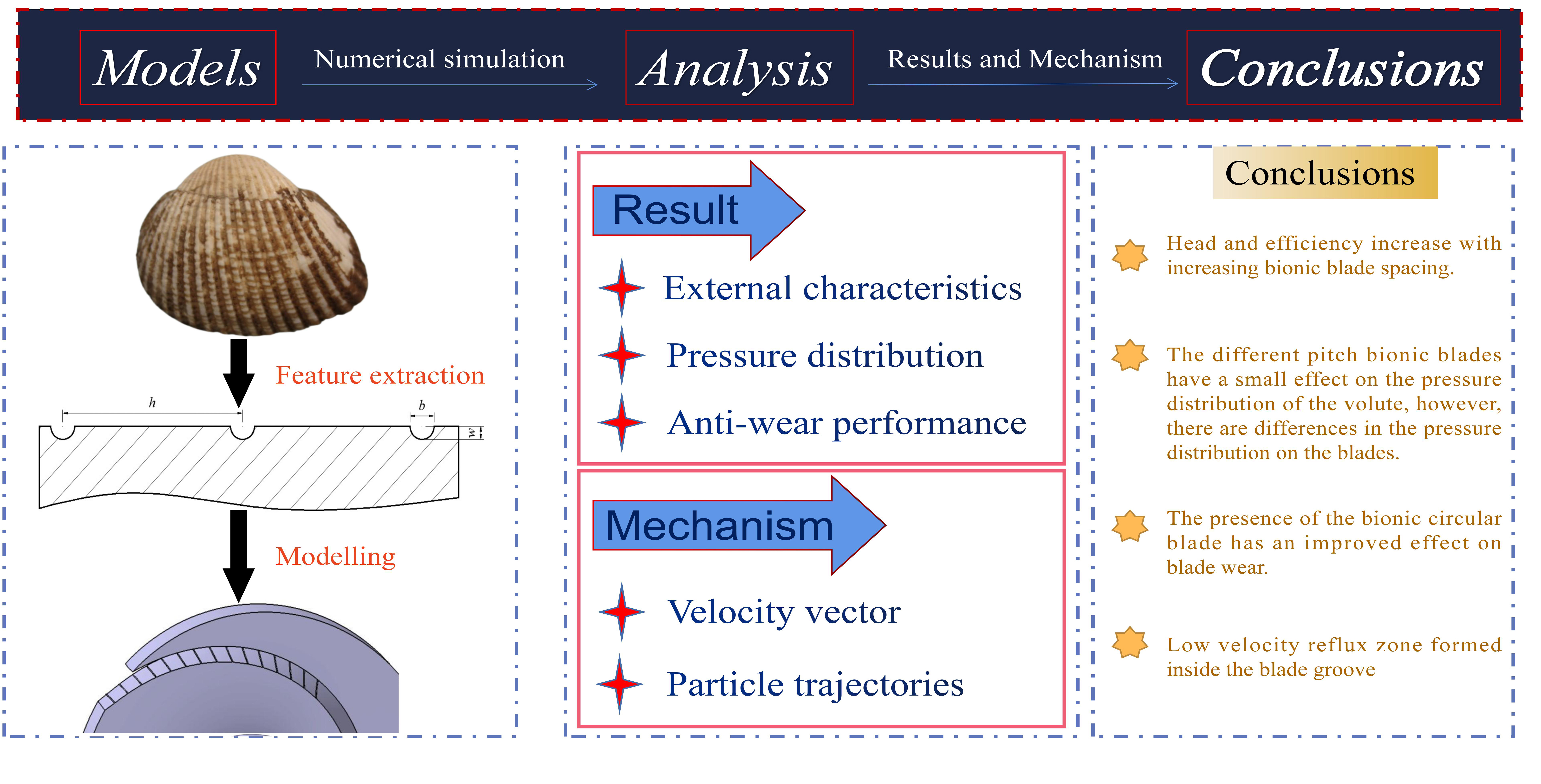
In order to reduce the variation in the samples themselves, shells without surface abrasion of approximately 40 ± 0.2 mm in length, 36 ± 0.2 mm in width, and 36 ± 2 mm in height were selected as the Scapharca subcrenata to be prepared. After removal of surface contaminants and adhesions from the shells using a brush and water, the Scapharca subcrenata were divided into two groups of seven. Group A is live, and Group B is dried after 96 h of washing and air-drying in a room under natural conditions. Both samples were prepared for measurement and observation. Taking into account the curvature of the Scapharca subcrenata surface, a square shell surface of 10 mm × 10 mm was taken along the middle groove and at a distance of 18 mm from the peak curvature point (PCP) [16] of the shell as the center of sampling. For the determination of the surface shape of the grooves, we observed the microstructure of the square surface of two kinds of Scapharca subcrenata using an electron microscope and found that the groove section of the Scapharca subcrenata is a trapezoidal structure. Electronic digital calipers are then used to determine the width d of the central groove and the spacing h between adjacent grooves, as shown in Figure 1a. To reduce errors, the data were measured five times for each sample. The width d and spacing data h for the measured samples were averaged separately to obtain a spacing of approximately 2.3 mm between the central groove and the adjacent groove, with a central groove width of approximately 0.42 mm.
The use of analogies, simulations, and models is an important feature of biological research. The purpose of bionics is not to directly replicate individual details, but to clarify how biological systems work in order to achieve specific functions. Considering the influence that the trapezoidal structure shape will have on the blade strength, blade structure, difficulty in processing shapes, original flow field, and hydraulic performance, the surface of the Scapharca subcrenata structure is reconstructed and optimized to construct a circular feature structure in line with the streamlined shape [12], as shown in Figure 1b. In addition, in order to reduce the size of the groove structure caused by the phenomenon of solid-phase particle agglomeration in the pump (which affects the increase in turbulent energy in the pump) and the frequent collision of the particles the and blade working surface, we reduced the surface structure parameters and increased the surface structure spacing. As shown in Figure 1b, the circular groove parameter was determined as d = 0.4 mm, where d is the diameter of the circular groove. The h in the picture represents the spacing between adjacent grooves; it was taken as 3, 5, 7, and 9 mm, respectively. Considering that the distance between the grooves will affect the distribution of the velocity and pressure fields inside the impeller, the number of circular grooves was determined as 15.
2.2. Computational Models
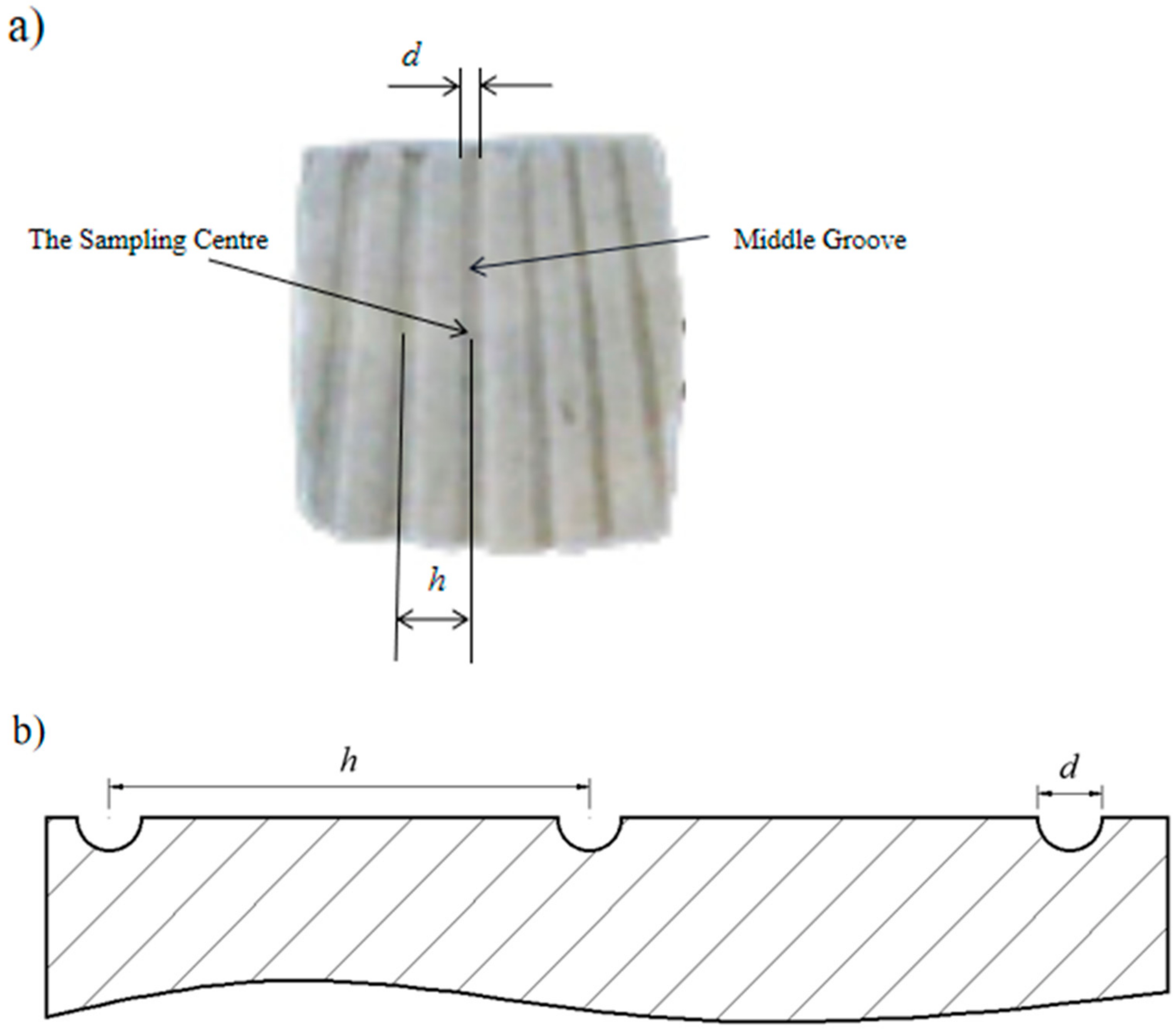
The 80ZW40-30 double-vane self-priming pump (Wenzhou Self-priming Pump Industry, Wenzhou, China) is used in calculation. The main performance parameters of the pump are the rated flow rate Q = 40 m3/h, rated head H = 30 m, and speed n = 2800 r/min. The structural parameters are the impeller inlet internal diameter D1 = 80 mm, the impeller inlet external diameter D2 = 164 mm, and the number of blades Z = 2. Due to the combined effect of the gravity of the solid phase particles, the virtual mass force, the interphase drag force, the kinetic energy contained in the particles, and the turbulent eddies in the flow field, the wear of the impeller is mainly concentrated on the suction side of the blade and is more serious at the outlet end. The groove structure affects the distribution of the velocity and pressure fields inside the impeller, so grooves are set up near the suction outlet end of the blade. The surface structure of the bionic circular blade with different groove spacing is shown in Figure 2.
2.3. Mesh Division and Parameter Setting
Due to the complex geometry of the fluid domain, an unstructured grid is used to divide the fluid region. Because the flow field at the volute tongue is complicated and the flow field is seriously separated, the mesh of the volute is encrypted. After the mesh independence test, the final number of meshes for each fluid domain was determined as 463,407 for the inlet pipe, 152,529 for the outlet pipe, 1,278,468 for the impeller, and 1,174,594 for the volute. A standard k-ε turbulence model with good robustness and reasonable prediction of large scale turbulence was selected for the numerical simulations [17]. Taking into account the effects of interphase drag and slip velocity, the turbulent multiphase flow model uses the discreate partical model, which is currently a more commonly used model for solid–liquid two-phase flow to investigate the inhibitory effect of bionic blades with different groove spacing on particle abrasive wear. During the numerical simulation, other wear, such as cavitation wear, corrosion wear, and erosion wear, was neglected. In terms of impeller wear, the Finnie erosion wear model predicts that the main areas of wear on the suction side of the blade are concentrated at the inlet and outlet ends, whereas the McLaury erosion wear model predicts that wear occurs at the inlet, outlet, and middle of the suction side of the blade, which is more similar to the actual situation [18,19].
In the McLaury erosion wear model, the wear rate is related to particle shape, angle of incidence, solid phase mass, and velocity. In numerical simulations, solid particles are considered spherical and mass invariant, so that the angle of incidence and velocity become the main influences on the wear rate [20,21,22].
The solid phase particles were calculated as SiO2, with a density of 2650 kg/m3 and a particle size of 0.5 mm. Simulated particle mass concentrations ρ of 0, 10, 30, 50, 70, and 90 kg/m3, and the solid phase particles, are considered to be uniformly distributed without phase transition. The SIMPLEC pressure-velocity coupling algorithm is used. The impeller fluid domain is partially selected as a slip grid, and the other fluid domains are selected as fine-stop coordinate systems; all walls are slip-free walls; the convergence accuracy is 10−4; the inlet of the discrete phase is the inlet pipe; the outlet of the outlet pipe is the only outlet of the discrete phase, and all other walls are set as reflective walls.
3. Characteristic Analysis of Double-Vane Pump
3.1. Analysis of External Characteristics
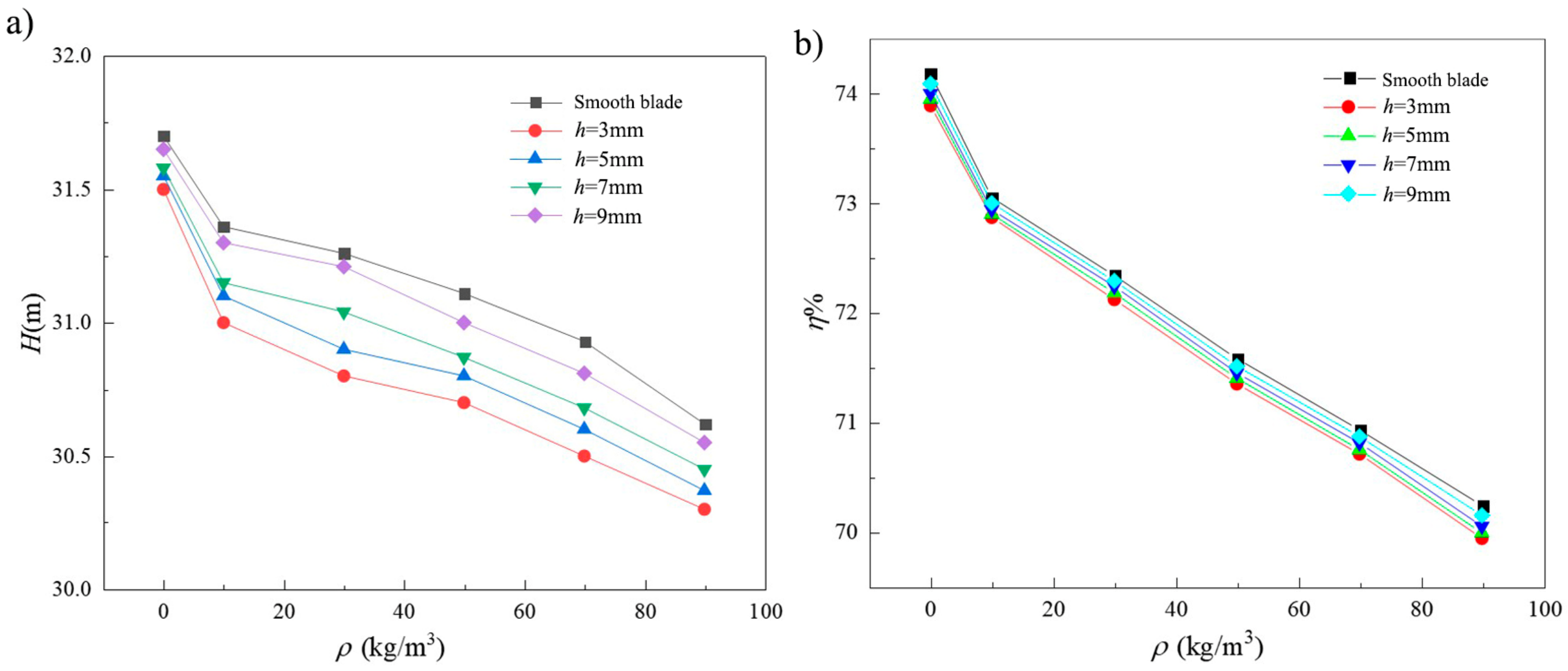
Figure 3 shows the external characteristic curves of the double-vane pumps with different groove spacing. As shown in Figure 3a, the head trend of all five double-vane pumps decreases with increasing solid phase particle concentration. The head has the greatest decrease, as ρ = 0 kg/m3 increases to ρ = 10 kg/m3. As is shown in Figure 3a, pumps with smooth vanes have the highest head. When the medium is water, the head value is ~31.7 m, which is higher than to the rated head of 30 m. This is because only the volute chamber and impeller are considered in the numerical simulation, and energy losses not related to the wear of the flow components in the gas-liquid separation chamber and the return orifice are ignored, while for ρ = 90 kg/m3 and h = 3 mm, the difference between the circular grooved blade and the smooth blade head is a maximum of 1.35%. That is within allowable error of ± 1.4%.
At the same concentration of particles, pumps with smooth vanes have the highest head. This is due to the presence of a circular groove surface structure, which changes the flow field on the surface of the blade, and the structure of the internal groove will form a low-speed backflow area. According to Stokes’ theorem, there is a positive relationship between the velocity of the fluid medium and the intensity of the vortex; the greater the velocity of the water, the greater the intensity of the vortex, resulting in greater fluid energy loss. By comparing the head of different circular groove spaced pumps at the same particle concentration, it is found that with decreased spacing, the greater the drop in head compared to a smooth blade. This is because in the case of a certain number of grooves, the increase in groove spacing makes the grooves more widely distributed. When h = 3 mm, the surface structure of the circular grooves is mainly concentrated at the outlet end of the blade, and the vortex zone formed by the dense circular grooves causes even greater kinetic energy consumption. However, with the excessive increase of groove spacing, the distribution range extends towards the blade inlet end area, the middle of the blade fluid velocity is small, the vortex intensity is small, and the consumption of medium energy in the flow field is small and dispersed, resulting in the reduction in the head with the increase in the groove spacing.
Figure 3b shows a graph of pump efficiency for the different circular groove spacings. The efficiency calculation method of the two-vane pump is different from that of the pure water medium when conveying a solid–liquid two-phase flow medium. The density of the solid-liquid two-phase flow, volume flow rate, pump head for conveying solid-liquid two-phase flow medium, gravity acceleration, and shaft power should be taken into account in the calculation. From the graph, it is seen that the efficiency trends and head trends of the five different blade pumps are similar. The efficiency of the pump gradually decreases as the concentration of particles increases. The greatest decrease in efficiency occurs when ρ = 0 kg/m3 increases to ρ = 10 kg/m3. At the same particle concentration, the efficiency of the pump increases with increasing groove spacing, but the decrease is small. The maximum difference in efficiency between h = 3 mm circular grooved blades and smooth blades is 1.08% when ρ = 90 kg/m3.
Therefore, the external characteristics of the double-vane pump are related to the groove spacing. However, the arrangement of the circular groove structure has a small effect on the pump head and efficiency performance. In practice, the reduction in external characteristics caused by the arrangement of the circular groove surface structure is within acceptable ranges.
3.2. Analysis of the Pressure Distribution in the Pump
3.2.1. Volute Pressure Distribution
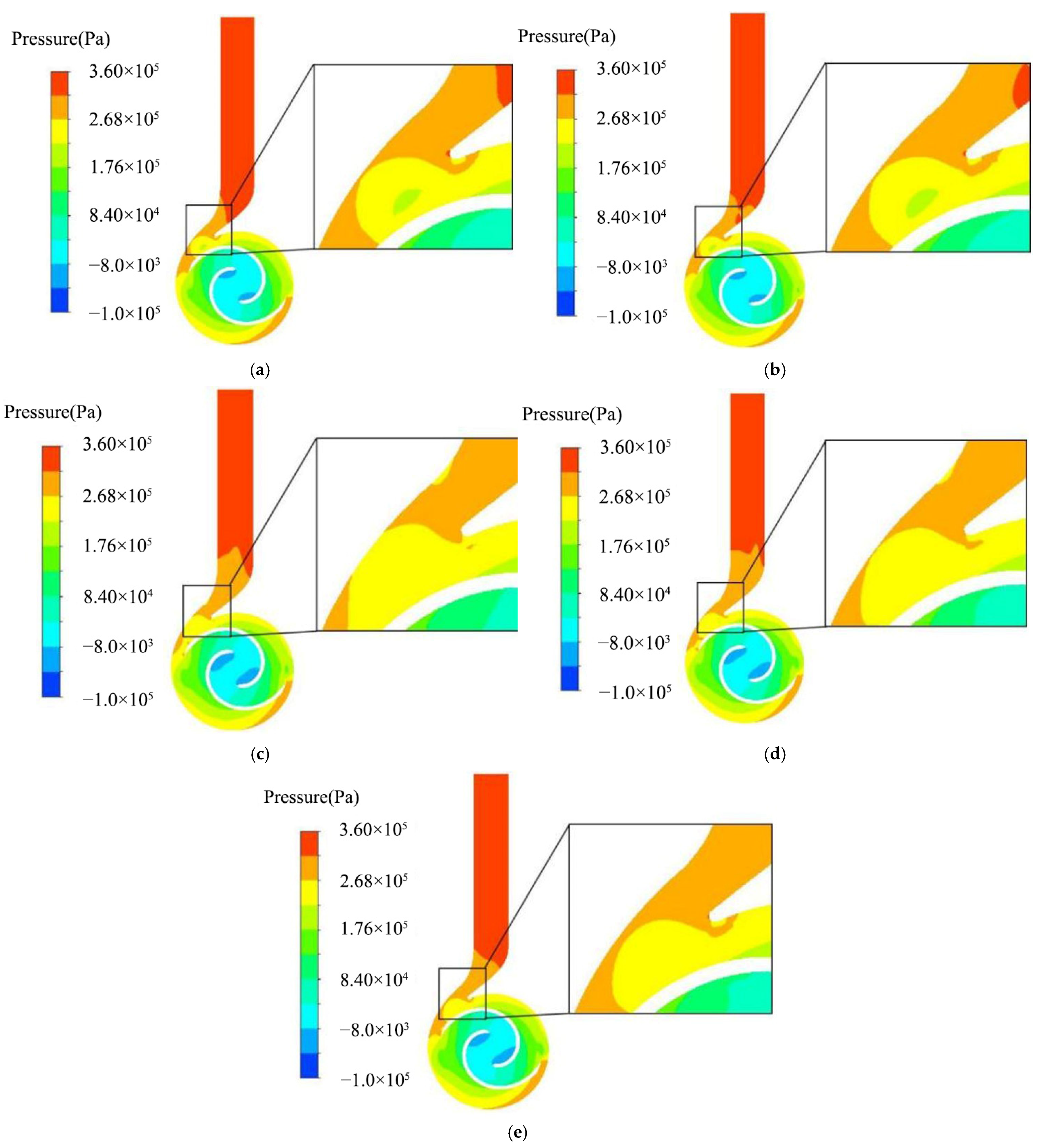
The internal pressure field of a two-vane pump, without the addition of solid-phase particles, is analyzed to understand the effect of different spaced groove configurations on the pump pressure distribution. Figure 4 shows a cloud of the pressure distribution in the pump section at different spacings for ρ = 0 kg/m3. The pressure is lowest at the inlet end of the blade and highest at the outlet of the volute. The pressure distribution of the impeller increases the gradient from the inlet end to outlet end, and the pressure distribution of different volutes is similar. The main difference between the four bionic blades lies in the pressure distribution at the front of the diffusion section of the volute, which is also enlarged in the figure. The pressure distribution in this area and the special structure of the cutwater are related to the dynamic and static interference produced by the fluid at the outlet end of the rotating blade. Analysis of the pressure field distribution in the impeller cross section shows that there is a high-speed, low-pressure region in the enlarged area of Figure 4a,b. The circular groove surface structure consumes fluid energy, which means that the velocity energy and pressure energy of the flow are reduced. Meanwhile, the increase in groove spacing results in a wider distribution of the vortex flow field. According to Bernoulli’s equation, the higher the velocity of the fluid, the lower its pressure. Therefore, as shown in Figure 4b–e, as the groove spacing increases, the pressure gradient in the pump is more evenly distributed. At the junction of the outlet tube and the diffuser section of the volute, the middle high pressure area gradually expands to the outlet tube with the increase in groove spacing, and the area covered by the medium to high pressure region increases and then decreases. The volute with the bionic blade has a smaller pressure gradient at the outlet end than the volute with the smooth blade. The presence of the groove promotes a more stable flow in the diffusion section of the volute and inhibits the impact of the fluid on the walls of the volute tongue and the volute diffusion section.
3.2.2. Blade Pressure Distribution
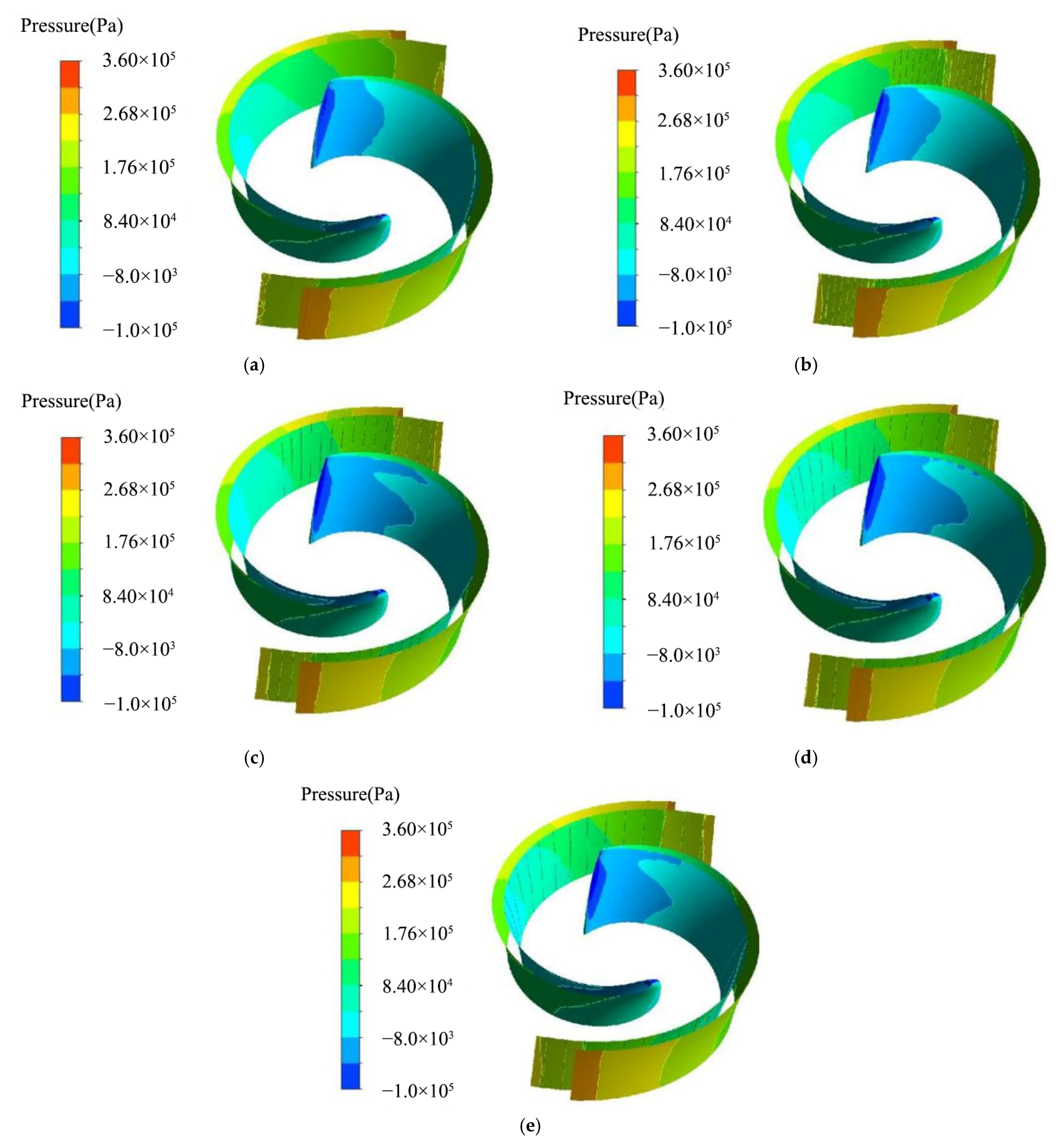
Figure 5 shows a cloud graph of the pressure distribution of the blades at different circular groove spacings for ρ = 0 kg/m3. As shown in Figure 5, the pressure on the suction side of the blade is significantly higher than on the pressure side of the blade, with a gradient in pressure distribution from the inlet end of the blade to the outlet end. A comparison of the pressure distribution at the outlet of each blade pressure surface shows that the high-speed and high-pressure zones in Figure 5c–e are more widely distributed than in Figure 5a,b. Comparing the pressure field at the inlet end of the suction surface of the blade, the distribution of the low-speed and low-pressure areas in Figure 5a,b is in the shape of a sinusoidal curve, with the wave peaks in the middle region of the suction surface. In contrast, the peaks in the low-pressure region in Figure 5c–e are mainly in the suction surface near the front casing cover area and middle region, and the peaks near the front casing cover area are not continuous in Figure 5d.
3.3. Analysis of Pump Anti-Wear Performance
3.3.1. Analysis of the Wear Resistance at Different Particle Concentrations
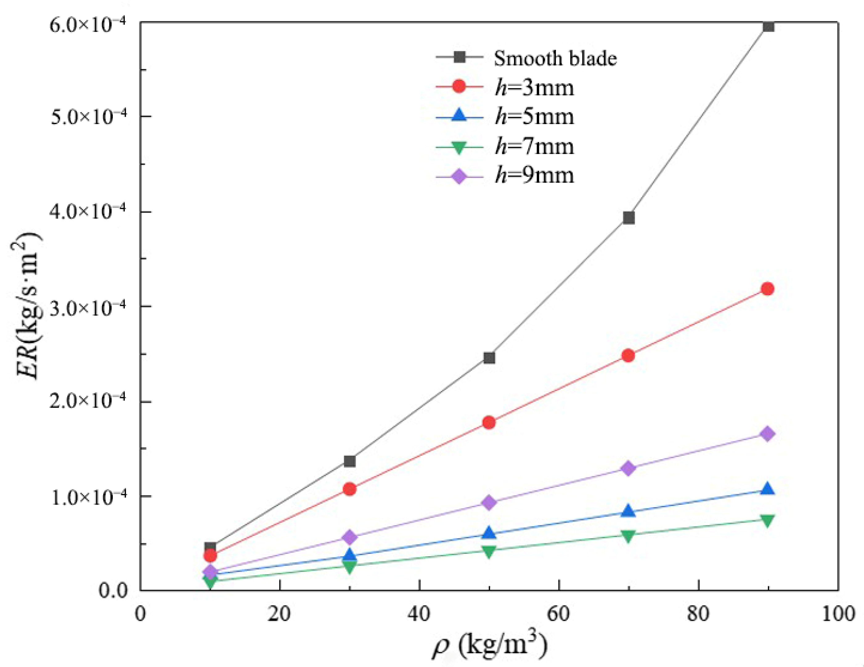
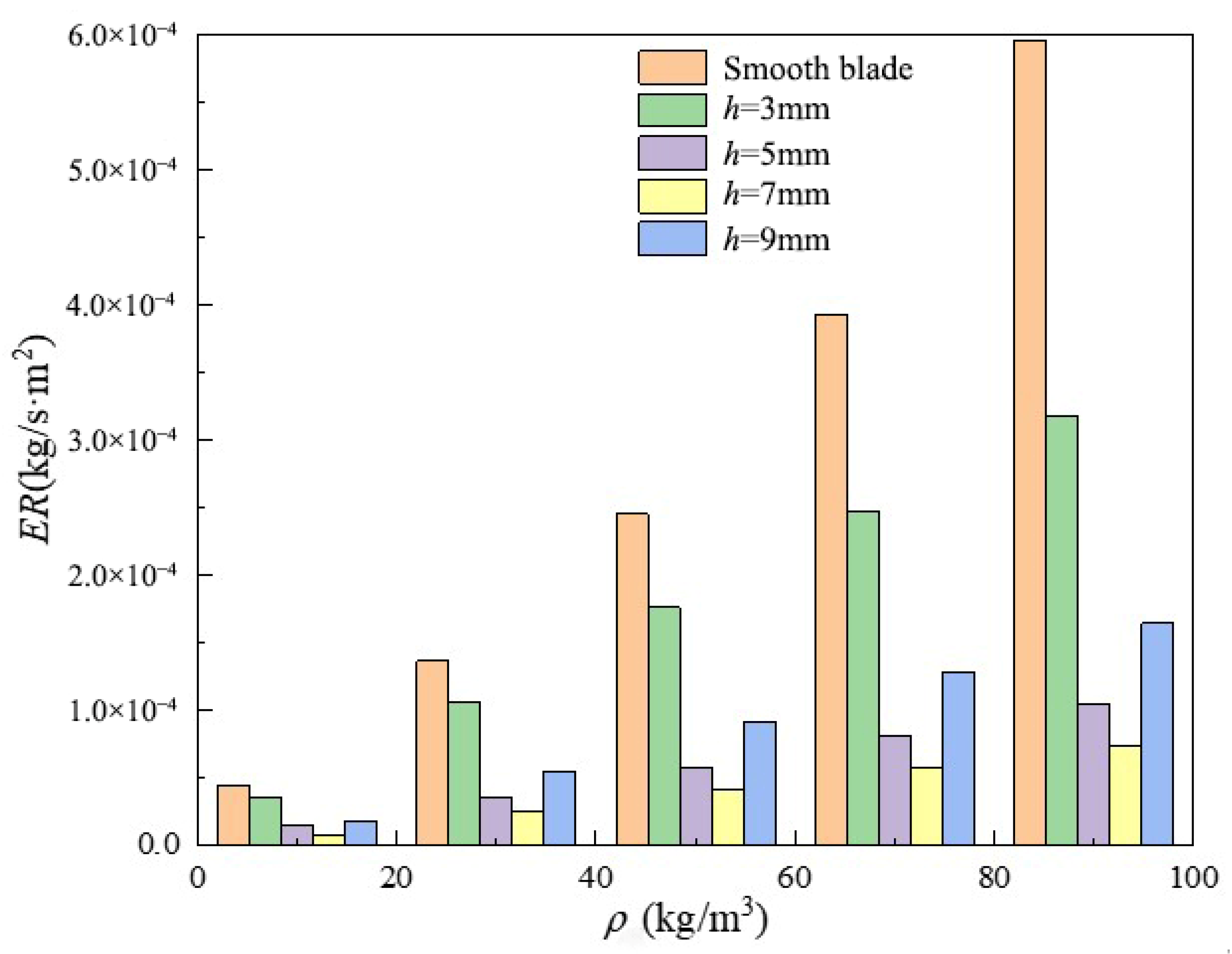
Figure 6 shows the average wear rate-particle concentration curves for smooth blades and four different groove-spaced bionic blades. Figure 7 shows the average wear rate-particle concentration histogram for smooth blades and four different groove pitch bionic blades. Figure 6 shows that the average wear rate of smooth blades increases exponentially with increasing particle concentration, while the average wear rate of bionic blades increases linearly. Figure 7 shows that the average wear rate of the bionic blade is lower than that of the smooth blade at the same particle concentration. When ρ = 90 kg/m3, the average wear rate of the bionic blade with a groove spacing of 3 mm is ~3.1 × 10⁻⁴ kg/s∙m2. As the groove spacing increases, the average wear rate of the blade decreases and then increases; h = 7 mm has the smallest average wear rate of ~0.63 × 10⁻⁴ kg/s∙m2. The average wear rate for h = 9mm is ~1.6 × 10⁻⁴ kg/s∙m2 less than for h = 3mm. Similar phenomena were found at other concentrations, which not only verifies that the groove spacing can influence the wear resistance of a double-vane pump, but also that the presence of a suitable groove spacing distance (around h = 7 mm) results in the lowest average wear rate and the best wear resistance of the blade. This is probably due to the fact that the distribution of the wear area on the suction side of the smooth blade is mainly concentrated on the blade outlet end and between the inlet and outlet ends, and the wear is more severe with the direction of fluid flow. When the groove spacing in the bionic structure is appropriate, the groove area encompasses the main wear area. The groove structure reduces the wear area and the degree of wear by changing the flow field. However, when the groove spacing is excessively large, a part of the groove structure will be arranged in the middle of the blade suction surface, which has little influence on the solid particles.
3.3.2. Analysis of Blade Wear Resistance at ρ = 90 kg/m3
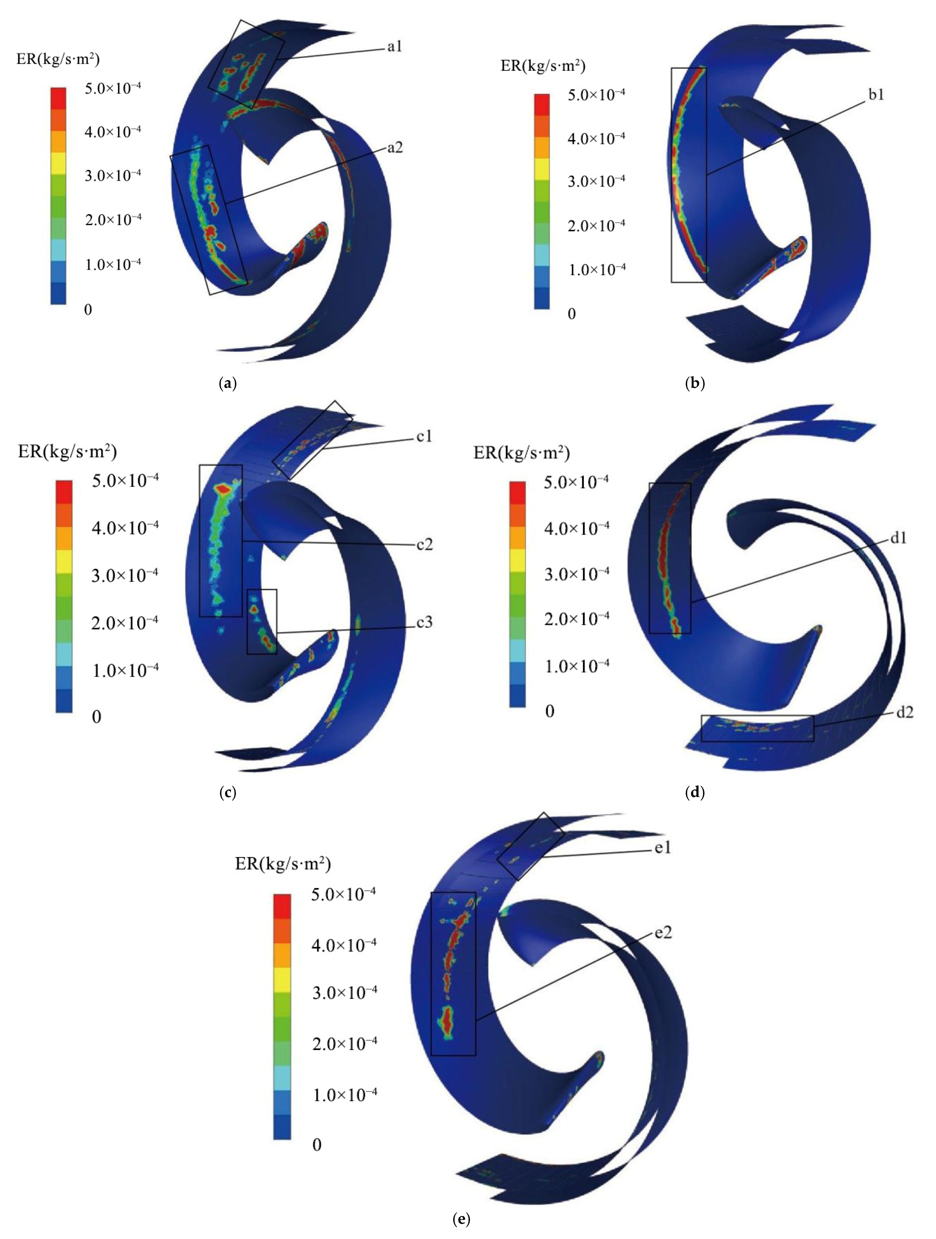
Figure 8 shows the wear clouds for the smooth blade and four different spaced-bionic blades at ρ = 90 kg/m3. The wear areas in Figure 8a are mainly concentrated at the inlet end of the blade, as shown in a1 and a2. In a1, there are wear blocks and wear bands that are aggravated by wear along the radial direction; in a2, the wear bands are predominant, and are mainly located close to the front casing cover.
In Figure 8b, the wear is concentrated at the inlet end and in b1. Due to the presence of axial flow in the flow field, a very distinct strip of wear is present at b1, with increased wear along the axial direction from right to left, while the non-smooth zone is almost free of wear areas.
In Figure 8c, the main wear zones are scattered across the inlet end, as shown in c1, c2, and c3. In c1, the wear area is located at the water outlet end of the blade suction surface near the rear casing cover, where the wear zone is intermittently distributed due to the “air cushion” effect of the low velocity reflux zone in the groove structure, which changes the trajectory of the solid phase particles. In c2, at the smooth area of the blade suction surface near the front casing cover, the overall shape resembles a trailing comet. The head of the comet is close to the non-smooth area where the wear is relatively severe, while the tail of the comet has a discontinuous and less severe wear area. This is due to the fluid kinetic energy of the solid phase particles carried from the inlet end of the blade to the outlet end, which increases, and the energy of the particles hitting the blade wall also increases. c3 shows that the wear zones are mainly distributed in the blade suction surface inlet end near the rear casing cover, which indicates that as the groove interval increases to a certain distance, the flow field inside the impeller is turbulent, and the particle flow trajectory is more random.
In Figure 8d, the distribution of the wear area is mainly concentrated at the inlet end, as in d1 and d2. d2 shows the wear area concentrated mainly at the outlet end, near the rear casing cover. The central part of the suction surface of the blade at d1 is severely worn and spreads in all directions.
In Figure 8e, the wear area is concentrated at the inlet end and, as shown in e1 and e2. In e1, it is located at the outlet end, and the wear distribution is mainly blocky and scattered randomly. e2 shows the wear area located at the middle of the suction surface of the blade, and the wear area is intermittent.
By comparing the wear conditions of the smooth blade and the bionic blade with four different groove spacings, it is obvious that the surface structure of the circular groove successfully “interrupts” the wear zone through its own flow field characteristics, and its arrangement improves the wear condition of the outlet end. The increase in groove spacing causes the wear area to move first from the blade edge to the middle of the blade and then to the blade edge, where it is connected to the front and rear end caps of the impeller. The aggregation of solid phase particles at the joint can lead to fracture and dislodgement in the casing cover and blade joint. When h > 7 mm, the blade suction surface wear area is concentrated in the middle, and the wear performance of the pump is improved.
4. Analysis of the Anti-Wear Mechanism
4.1. Analysis of the Velocity Vector
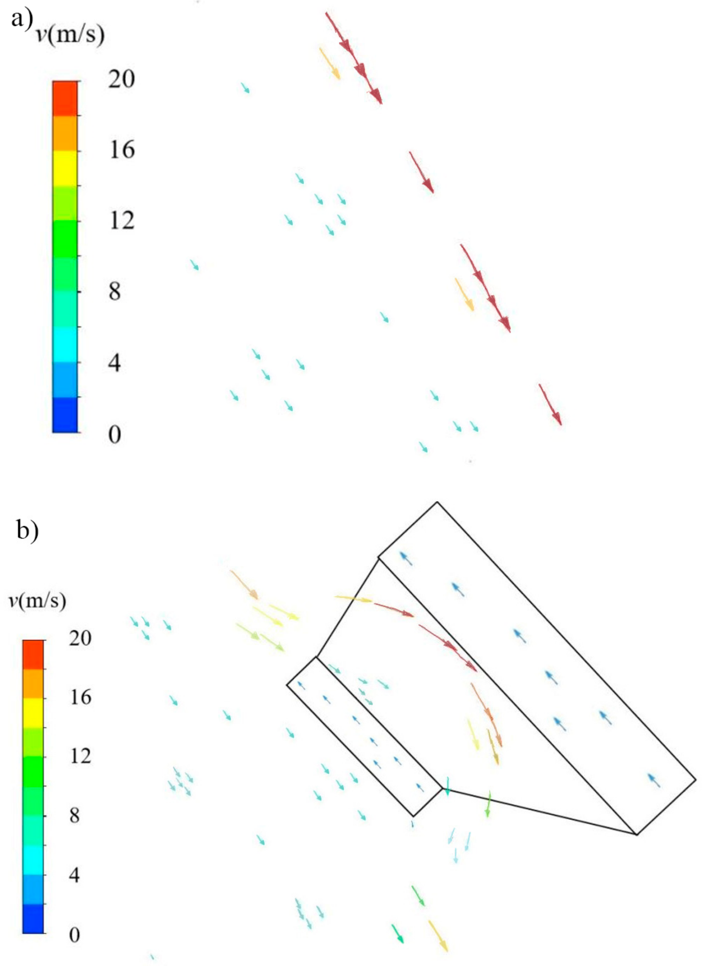
Figure 9 shows the smooth blade and bionic blade fluid velocity vector diagrams for water conditions. Due to the small size and large number of gravel particles selected, it is difficult to capture the trajectory of the particles in the two-dimensional cross section in the numerical simulation process, and the trajectory of the solid-phase particles in the two-dimensional cross section in the blades cannot be observed visually. Therefore, by studying how the circular groove structure changes the magnitude and direction of the velocity of the flow field under water conditions, the relationship between the groove structure and the formation of the vortex zone and the actual role played by the vortex zone in the solid–liquid two-phase flow field is sought.
It can be seen from Figure 9 that the velocities are higher at the edges of two kinds of blades and lower away from the blade edges, which is consistent with the boundary layer velocity distribution. The difference is that the fluid velocity decreases after the corner is encountered in Figure 9b, which explains the lower head and efficiency performance of the pump under the bionic blade compared to the smooth blade. In addition, from the fluid velocity vector diagram of the bionic blade in Figure 9b, it is obvious that a low velocity backflow zone is formed inside the circular groove. The fluid at the bottom of the trench is in the same direction as the mainstream velocity, while the velocity inside the trench is in the opposite direction to the mainstream velocity, and the mainstream field velocity is less than the fluid velocity at the bottom of the trench. This means that there is a reverse vortex inside the groove that provides an “air cushion” smooth area in the solid phase where the direct contact of the particles and blade wall cause a collision formation wear area. The non-smooth zone can neutralize the impact force of the solid phase particles and change the velocity, size, and direction of the particles through the action of the vortex, reducing the frequency and chance of direct collision between the particles and the blade wall, which can improve the anti-wear performance of the blade wall, to a certain extent.
4.2. Analysis of Particle Trajectories
Figure 10 shows the liquid streamline and particle traces for two different blade pumps at ρ = 90 kg/m3. Comparing the liquid phase flow lines and particle traces of the smooth blade and the bionic blade pump with d = 0.40 mm and h = 7 mm, it is found that when the pump with smooth blade starts to operate, the input solid phase particles and the liquid phase fluid start to pre-swirl before entering the impeller flow path. Once the solid phase particles have entered the impeller flow path, the liquid phase fluid carries the particles in the flow path in a pre-circular motion. The pressure surface of the blade works by direct contact with the liquid phase fluid, and the pressure surface is not in direct contact with the particles. After the transport medium enters the flow channel, the solid phase particles are much denser than the liquid phase fluid, so the traces of the solid phase particles are approximately 45°, as shown in the area of Figure 10a and 1b of Figure 10b, behind the phase of the liquid streamline. In addition, the density of solid particles is higher than that of liquid fluid. Under the action of inertia, the distribution of solid particles in the volute flow channel is more concentrated near the volute wall, causing more serious erosion wear on the volute wall. At the outlet of the volute in 1a of Figure 10a, the trace lines of solid particles are mainly spiraling out along the volute wall, while the liquid streamline almost fills the entire outlet channel of the volute. In Figure 10a,b, although the solid phase particle hysteresis angle is greater with the bionic blade pump than with the smooth blade pump, the particle trajectories are more concentrated and further away from the blade pressure surface. The concentration of particle traces makes it appear that the particle trajectories do not come into contact with the grooves and appear to jump from one area to another, which is related to the low velocity reflux zone inside the grooves.
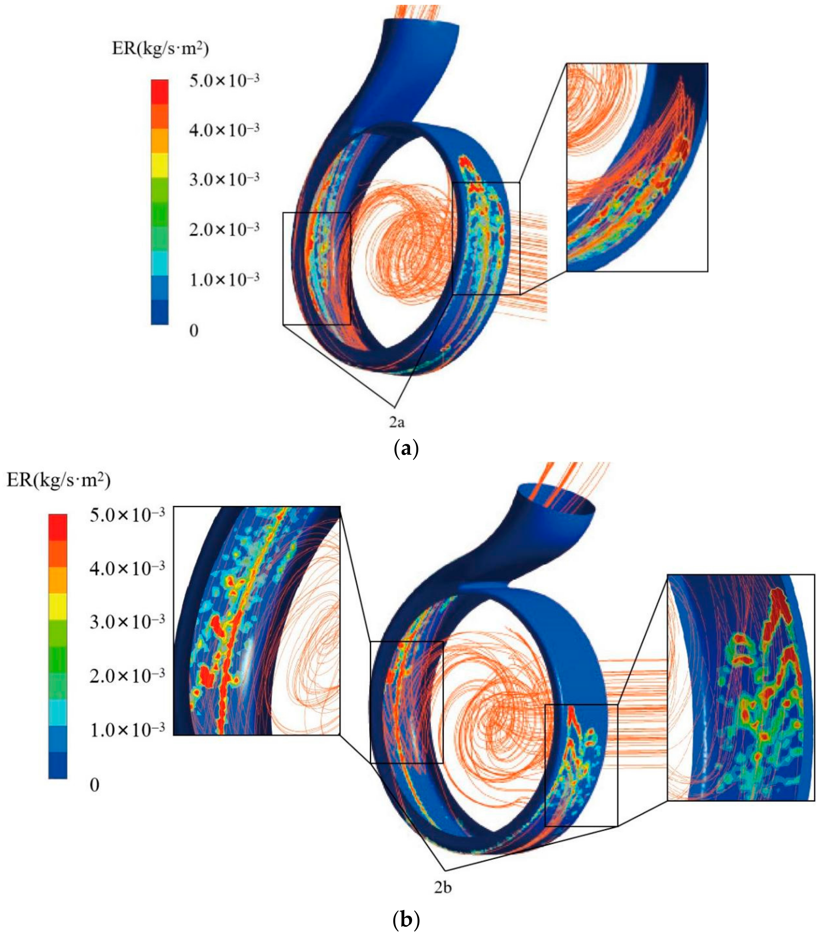
Figure 11 shows the cloud diagram of volute particle trajectory and wear rate for two different blades at ρ = 90 kg/m3. Due to particle hysteresis and the direction of flow of the solid phase particles carried by the liquid inside the impeller runner, no wear occurs at the cutwater to the front half of the volute wall. The wear-free area in Figure 11b is more extensive than in Figure 11a. Combined with 2a, 2b of Figure 11, the wedge-shaped distribution of the volute wall wear is caused. It can be seen that the solid phase particles in the volute are mainly concentrated on the volute wall, which is the cause of the large wear area and high wear rate on the volute wall surface. The fluid medium is not only subject to radial forces from the impeller in the overflow components, but also to axial forces. This means that the volute wall will collide with particles in the flow field; as shown in 2a of Figure 11, the wear area is divided into three main parts: left, middle, and right.
5. Conclusions
- At the same particle concentration, the pump head and efficiency increase with the increase of bionic blade spacing, and the pump head and the efficiency of the smooth blade are the highest.
- The bionic blade has a small effect on the pressure distribution of the volute. However, the pressure distribution is different for different blades. The bionic blades have a uniformly regular distribution of high-pressure areas on the suction side, and crest of the low-pressure area at the inlet is mainly near the front end cover and the middle position of the suction.
- The presence of the bionic circular blade has an improved effect on blade wear. At the same particle concentration, the average wear rate of the blade increases and then decreases as the distance between the grooves increases, with the average wear rate at h = 7 mm being the smallest. The wear area moves from the blade edge to the middle blade first, and then to the joint between the blade edge and the impeller cover.
- Due to the existence of the circular groove structure, the particle trajectory hysteresis angle is greater in the pump with the bionic blade compared to pump with the smooth blade, but the particle trajectory is more concentrated. The low velocity reflux zone formed on the suction side of the blades not only reduces the contact between the particles and the wall, but also neutralizes the impact of the particles; thus, the pump with d = 0.40 mm and h = 7 mm has the best wear resistance.
Author Contributions
Conceptualization, L.M. and Y.G.; methodology, L.M.; software, K.X.; validation, C.M., D.W. and M.Y.; formal analysis, L.M.; investigation, L.M.; resources, Y.G.; data curation, Y.G. and J.M.; writing—original draft preparation, L.M.; writing—review and editing, Y.G., C.M. and J.M.; visualization, K.X.; supervision, K.X.; project administration, L.M., Y.G. and J.M.; funding acquisition, L.M., Y.G. and J.M. All authors have read and agreed to the published version of the manuscript.
Funding
This work was supported by the Zhejiang Provincial Natural Science Foundation of China (Grant No. LY22E050015), the Science and Technology Plan Project of the State Administration for Market Regulation (Grant No. 2020MK192), the Zhejiang Provincial Science and Technology Plan Project of China (Grant No. 2021C01052), and the Zhejiang University Students Science and Technology Innovation Program (Grant No. 2022R409041).
Data Availability Statement
The data presented in this study are available on request from the corresponding author.
Conflicts of Interest
The authors declare no conflict of interest.
References
- Peng, G.; Chen, Q.; Bai, L.; Hu, Z.; Zhou, L.; Huang, X. Wear Mechanism investigation in a centrifugal slurry pump impeller by numerical simulation and experiments. Eng. Fail. Anal. 2021, 128, 105637. [Google Scholar] [CrossRef]
- Tarodiya, R.; Gandhi, B.K. Numerical investigation of erosive wear of a centrifugal slurry pump due to solid–liquid flow. J. Tribol. 2021, 143, 101702. [Google Scholar] [CrossRef]
- Wu, B.; Wang, X.; Liu, H.; Xu, H. Numerical simulation and analysis of solid-liquid two-phase three-dimensional unsteady flow in centrifugal slurry pump. J. Cent. South Univ. 2015, 22, 3008–3016. [Google Scholar] [CrossRef]
- Zhang, W.; Yang, S.; Wu, D.; Mou, J. Effect of particle mass concentration on erosion characteristics of self-priming pump. Proc. Inst. Mech. Eng. Part C J. Mech. Eng. Sci. 2021, 235, 6782–6797. [Google Scholar] [CrossRef]
- Heng, Q.; Jiegang, M.; Yun, R.; Zhibing, Z.; Nuojia, L.; Shuihua, Z.; Denghao, W. Investigation of self-priming process of a centrifugal pump with double blades. J. Therm. Sci. 2021, 30, 849–858. [Google Scholar]
- Gu, Y.; Yu, L.; Mou, J.; Wu, D.; Xu, M.; Zhou, P.; Ren, Y. Research strategies to develop environmentally friendly marine antifouling coatings. Mar. Drugs 2020, 18, 371. [Google Scholar] [CrossRef]
- He, C.; Gu, Y.; Zhang, J.; Ma, L.; Yan, M.; Mou, J.; Ren, Y. Preparation and modification technology analysis of ionic polymer-metal composites (IPMCs). Int. J. Mol. Sci. 2022, 23, 3522. [Google Scholar] [CrossRef]
- Bejjani, R.; Collin, M. Three Dimensional Topographic studies on worn surfaces of coated cemented carbide tools with different workpiece materials. CIRP J. Manuf. Sci. Technol. 2016, 14, 76–79. [Google Scholar] [CrossRef]
- Gu, Y.; Yu, S.; Mou, J.; Wu, D.; Zheng, S. Research progress on the collaborative drag reduction effect of polymers and surfactants. Materials 2020, 13, 444. [Google Scholar] [CrossRef] [Green Version]
- Zang, X.; Cao, X.; Zhang, J.; Xie, Z.; Xiong, N.; Darihaki, F.; Bian, J. Investigation of surface damage of ductile materials caused by rotating particles. Wear 2022, 488–489, 204185. [Google Scholar] [CrossRef]
- Mou, J.; Zhang, Z.; Gu, Y.; Shi, Z.; Zheng, S. Effect of circular non-smooth surface vanes on cavitation characteristics of centrifugal pump. J. Shanghai Jiaotong Univ. 2020, 54, 577–583. [Google Scholar] [CrossRef]
- Ma, L.; Gu, Y.; Xia, K.; Mou, J.; Wu, D.; Yan, M. Effect of bionic nonsmooth surface vane on the antiwear characteristics of double-vane pump. Appl. Bionics Biomech. 2022, 2022, e4442417. [Google Scholar] [CrossRef] [PubMed]
- Dai, C.; Guo, C.; Ge, Z.; Liu, H.; Dong, L. Study on drag and noise reduction of bionic blade of centrifugal pump and mechanism. J. Bionic Eng. 2021, 18, 428–440. [Google Scholar] [CrossRef]
- Xiao, G.; He, Y.; Zhou, K.; Zhu, S.; Song, S.; Song, K. A Study on aerodynamic performance of different bionic-structured surfaces via belt grinding. J. Bionic Eng. 2021, 18, 1179–1191. [Google Scholar] [CrossRef]
- Tian, X.; Han, Z.; Li, X.; Pu, Z.; Ren, L. Biological coupling anti-wear properties of three typical molluscan shells—Scapharca subcrenata, Rapana venosa and Acanthochiton rubrolineatus. Sci. China Technol. Sci. 2010, 53, 2905–2913. [Google Scholar] [CrossRef]
- Tian, L.; Tian, X.; Wang, Y.; Hu, G.; Ren, L. Anti-wear properties of the molluscan shell Scapharca subcrenata: Influence of surface morphology, structure and organic material on the elementary wear process. Mater. Sci. Eng. C 2014, 42, 7–14. [Google Scholar] [CrossRef]
- Wang, F. Research progress of computational model for rotating turbulent flow in fluid machinery. Trans. Chin. Soc. Agric. Mach. 2016, 47, 1–14. [Google Scholar]
- Tarodiya, R.; Gandhi, B.K. Hydraulic performance and erosive wear of centrifugal slurry pumps—A review. Powder Technol. 2017, 305, 27–38. [Google Scholar] [CrossRef]
- Poursaeidi, E.; Tafrishi, H.; Amani, H. Experimental-numerical investigation for predicting erosion in the first stage of an axial compressor. Powder Technol. 2017, 306, 80–87. [Google Scholar] [CrossRef]
- Edwards, J.K.; McLaury, B.S.; Shirazi, S.A. Modeling solid particle erosion in elbows and plugged tees. J. Energy Resour. Technol. 2001, 123, 277–284. [Google Scholar] [CrossRef]
- Shen, Z.; Chu, W.; Dong, W. Effect of particle parameters on flow field and erosion wear characteristics of flow passage components in screw centrifugal pump. Nongye Gongcheng Xuebao Trans. Chin. Soc. Agric. Eng. 2018, 34, 58–66. [Google Scholar] [CrossRef]
- Zhang, Y.; McLaury, B.S.; Shirazi, S.A. Improvements of particle near-wall velocity and erosion predictions using a commercial cfd code. J. Fluids Eng. 2009, 131, 031303. [Google Scholar] [CrossRef]
Figure 1.
Biological characteristics of Scapharca subcrenata. (a) Local features on the surface of Scapharca subcrenata; (b) Schematic of feature reconstruction.
Figure 1.
Biological characteristics of Scapharca subcrenata. (a) Local features on the surface of Scapharca subcrenata; (b) Schematic of feature reconstruction.

Figure 2.
Fluid domain of the impeller of a bionic blade with different groove spacing. (a) h = 3 mm; (b) h = 5 mm; (c) h = 7 mm; (d) h = 9 mm.
Figure 2.
Fluid domain of the impeller of a bionic blade with different groove spacing. (a) h = 3 mm; (b) h = 5 mm; (c) h = 7 mm; (d) h = 9 mm.

Figure 3.
External characteristic curves of pumps with different circular groove spacing. (a) Pump head-particle concentration line chart with different blades; (b) pump efficiency-particle concentration line chart with different blades.
Figure 3.
External characteristic curves of pumps with different circular groove spacing. (a) Pump head-particle concentration line chart with different blades; (b) pump efficiency-particle concentration line chart with different blades.

Figure 4.
Pressure cloud diagram of pump sections with different blades. (a) Smooth blades; (b) h = 3 mm; (c) h = 5 mm; (d) h = 7 mm; (e) h = 9 mm.
Figure 4.
Pressure cloud diagram of pump sections with different blades. (a) Smooth blades; (b) h = 3 mm; (c) h = 5 mm; (d) h = 7 mm; (e) h = 9 mm.

Figure 5.
Cloud diagram of blade pressure distribution at different blades. (a) Smooth blades; (b) h = 3 mm; (c) h = 5 mm; (d) h = 7 mm; (e) h = 9 mm.
Figure 5.
Cloud diagram of blade pressure distribution at different blades. (a) Smooth blades; (b) h = 3 mm; (c) h = 5 mm; (d) h = 7 mm; (e) h = 9 mm.

Figure 6.
Average wear rate-particle concentration curve for different blade pumps.

Figure 7.
Histogram of average wear rate-particle concentration for different blade pumps.

Figure 8.
Wear cloud diagram of a smooth blade and four different bionic blades. (a) Smooth blades; (b) h = 3 mm; (c) h = 5 mm; (d) h = 7 mm; (e) h = 9 mm.
Figure 8.
Wear cloud diagram of a smooth blade and four different bionic blades. (a) Smooth blades; (b) h = 3 mm; (c) h = 5 mm; (d) h = 7 mm; (e) h = 9 mm.

Figure 9.
Velocity vectors of fluid in different blades. (a) Smooth blade; (b) Bionic blade.

Figure 10.
Liquid streamline (blue) and particle trace (red) of pumps with different blades. (a) Smooth blade; (b) Bionic blade.
Figure 10.
Liquid streamline (blue) and particle trace (red) of pumps with different blades. (a) Smooth blade; (b) Bionic blade.

Figure 11.
Cloud diagram of volute particle trajectory and wear rate for two different blades. (a) Smooth blade; (b) Bionic blade.
Figure 11.
Cloud diagram of volute particle trajectory and wear rate for two different blades. (a) Smooth blade; (b) Bionic blade.

Publisher’s Note: MDPI stays neutral with regard to jurisdictional claims in published maps and institutional affiliations. |
© 2022 by the authors. Licensee MDPI, Basel, Switzerland. This article is an open access article distributed under the terms and conditions of the Creative Commons Attribution (CC BY) license (https://creativecommons.org/licenses/by/4.0/).
Share and Cite
MDPI and ACS Style
Ma, L.; Gu, Y.; Xia, K.; Mou, C.; Mou, J.; Wu, D.; Yan, M. Influence of Bionic Circular Groove Blade Surface on Wear Performance. Lubricants 2022, 10, 101. https://0-doi-org.brum.beds.ac.uk/10.3390/lubricants10050101
AMA Style
Ma L, Gu Y, Xia K, Mou C, Mou J, Wu D, Yan M. Influence of Bionic Circular Groove Blade Surface on Wear Performance. Lubricants. 2022; 10(5):101. https://0-doi-org.brum.beds.ac.uk/10.3390/lubricants10050101
Chicago/Turabian StyleMa, Longbiao, Yunqing Gu, Ke Xia, Chengqi Mou, Jiegang Mou, Denghao Wu, and Muhan Yan. 2022. "Influence of Bionic Circular Groove Blade Surface on Wear Performance" Lubricants 10, no. 5: 101. https://0-doi-org.brum.beds.ac.uk/10.3390/lubricants10050101
Note that from the first issue of 2016, this journal uses article numbers instead of page numbers. See further details here.