Development of a Cryogenic Tester with Air Bearing to Test Sliding-Rolling Contact Friction

School of Mechatronics Engineering, Henan University of Science and Technology, Luoyang 471003, China
*
Author to whom correspondence should be addressed.
Lubricants 2022, 10(6), 119; https://0-doi-org.brum.beds.ac.uk/10.3390/lubricants10060119
Submission received: 22 April 2022
/
Revised: 27 May 2022
/
Accepted: 30 May 2022
/
Published: 7 June 2022
Abstract
:This study aimed to test the friction coefficient of cryogenic bearing lubrication materials. A ball-on-disc type friction tester was developed in our lab using air bearings that could simulate the movement of cryogenic bearings under sliding-rolling contact. The tester is equipped with a temperature-controlled chamber to provide a minimum −175 °C low-temperature environment. Using air bearings is an important technique to reduce the base friction of the tester measurement system and ensure the accuracy of the friction coefficient measurement. The friction coefficients of the Ag coating and the PTFE coating were measured at different sliding-rolling velocities on this tester, and the results showed that the friction coefficient curves agreed well with the Gupta sliding model. The developed tester will provide important data for the dynamic analysis and life evaluation of the cryogenic bearings.
1. Introduction
The problems of lubrication in the modern industry are the research objects of the moving mechanisms and moving parts of various industrial equipment, including basic components such as rolling bearings and gears. As an important basic component, the failure of a rolling bearing can lead to catastrophic consequences [1]. Bearings used in the aerospace industry usually operate under extremely harsh conditions such as cryogenic temperatures, heavy loads, and high rotational speeds [2]. In cryogenic environments, oil and grease lubrication for bearings is not possible owing to the extreme temperature conditions. Therefore, solid lubricants such as polytetrafluoroethylene (PTFE) and Ag are usually used as cage materials for roll bearings because they have a low coefficient of friction. Burris [3,4,5] investigated the friction characteristics of PTFE according to a temperature gradient of 190–420 K and identified the range in which the friction coefficient was affected by the temperature. Qian jing et al. [6] investigated the tribological and mechanical properties of PTFE-based solid lubricating coatings. During the operation of the bearing, this self-lubricating material forms a stable transfer film on the contact surface through frictional and wear in order to provide a lubricating effect for the bearing. Cryogenic bearings’ lubrication modes are complex and various; field tests with bearings are extremely difficult and the test data are poor, which makes their dynamics analysis and life evaluation difficult. Friction coefficient, as one of the key parameters of cryogenic bearing lubricants, has an important influence on the dynamic analysis and life evaluation of cryogenic bearings. Therefore, it is important to develop a cryogenic friction tester to simulate the cryogenic bearing motion conditions.
Many scholars have studied the friction and wear phenomena of roll-element bearings under specific working conditions by using homemade testing machines. Previously, Gupta [7] constructed a friction model to investigate the solid lubrication mechanism and proposed a friction coefficient curve according to the operating conditions and as a function of sliding (slip) using experimental results. Jun Hyeon Jo et al. [8] verified the working stability of the liquid rocket engine turbopump unit in a liquid nitrogen environment using a self-developed ball bearing cryogenic test rig. Later, Bokseong Choe et al. [9,10] studied the dynamic behavior of a ball-bearing bearing cage submerged in a cryogenic fluid under different cage clearances and rotation speeds using this ball-bearing cryogenic test rig. Wonil Kwak et al. [11] obtained the friction coefficients of the PTFE coating and Ag coating at different sliding speeds using a self-made cryogenic ball-on-disc rig. Jun Wang et al. developed a friction tester for simulating the point contact of high-speed rotating parts [12] and conducted a related study [13]. The ball-on-disc tester was developed by Yang Boyuan et al. of Henan University of Science and Technology to study the traction characteristics of the lubricant under simulated bearing point contact conditions [14,15] and conduct an experimental study of the bearing lubricant under partial working conditions [16,17,18,19,20]. Zhang Wenhu [21] et al. conducted a large number of experiments on elastodynamic traction using this tester and obtained the formulae for calculating the elastodynamic traction coefficients of four aviation lubricants. This provides a theoretical basis for the selection of aviation lubricants.
In this study, based on the original bearing tester in Henan University of Science and Technology, a ball-on-disc type sliding-rolling contact friction tester was developed for cryogenic bearing lubricant in our lab with air bearings. The tester is assembled with a temperature-controlled chamber, which can achieve a cryogenic environment with a minimum of −175 °C using liquid nitrogen. The use of air bearings minimizes the base friction of the measurement system and ensures the accuracy of its friction coefficient measurement. This tester has the characteristics of the cryogenic environment, high-speed heavy load, and high automation.
2. Principle of the Tester
Rolling, sliding, and slip phenomena occur simultaneously in the roll bearings during operation. In this study, a ball-on-disc type cryogenic tester was developed to simulate these motion phenomena in cryogenic environments. The ball-on-disc type tester is simple in structure, has small experimental components, and can better simulate the motion characteristics of cryogenic ball bearings. When the ball and disc specimens slide relative to each other, the lubricant between them creates a lubrication film, which generates a frictional force. The ball and disc specimens of this tester are independent motion units. The rotation speed of the ball and disc specimens can be adjusted to run in a sliding-rolling state. From the third chapter, the ball axis of rotation is horizontal and in the same plane as the vertical axis of the disc. Therefore, the effect of spin on the rolling velocity can be ignored, and the rolling velocity is defined as follows:
where is the linear velocity of the ball specimen at the contact point and is the linear velocity of the disc specimen at the contact point. The sliding velocity is defined as:
The slide-to-roll ratio is defined as the ratio of sliding velocity to rolling velocity:
The rotating speeds of ball and disc specimens are, respectively:
where is the radius of the ball specimen and is the distance from the contact point to the center of the disc specimen.
During the test, two frequency converters are used to change the rotational speed of the ball and disc specimens, which makes the ball and disc turn from a pure rolling state to a sliding-rolling contact state. The relationship between the rotational speed of the ball and disc specimens and the slide-to-roll ratio is:
where is the slide-to-roll ratio, is the ball specimen rotation speed, and is the disc specimen rotation speed.
A cryogenic bearing lubrication material friction characteristics test was used to test the friction force between the ball and disc specimens at different sliding velocities under the conditions of a given rolling velocity and load . We obtain the coefficient of friction μ () as a function of the sliding velocity .
Measurement accuracy is one of the most critical indicators of a tester. This tester uses an air-floating shaft as the rotating support. Since the rotating friction of the air-floating shaft is much smaller than the friction between the ball and disc specimen, the measuring system error can be effectively reduced, and the measuring accuracy can be ensured. The described air-floating shaft type is ZCS-KZ120 (Luoyang, China), which consists of two air bearings. The air inlet is a circumferential, annular, slit-type air inlet with little air diffusion and circulation influence, a smooth surface, and good bearing stability. Table 1 lists the main parameters of the air shaft. In addition, the tester has some auxiliary parts for the purpose of completing the experiment. These are shown in Figure 1. The load sensor and friction force sensor selected by the tester are produced by BEDELL Electronic Technology Co., Ltd. (Shanghai, China), and the model is 102 A. The main performance indicators of the load sensors and friction sensors are as follows: 1. Load sensor range: 0–2000 N. 2. Friction force sensor range: 0–50 N. 3. Sensitivity: 0–1000 Kg, 1.0 mv/V. 4. Linearity: ± 0.1%/FS. 5. Hysteresis error: 0.1%/FS. 6. Repeatability error: 0.1%/FS. 7. Zero-point error: 10%/FS. The sensor used in the tester can ensure that the friction measurement error is less than 0.1 N.
Considering the actual working environment of cryogenic bearings, the tester developed in this study meets the following technical requirements for low-temperature solid friction wear testing under different working conditions: (1) The range of rolling velocity is 1–50 m/s, and the velocities can be changed stepless; (2) The slide-to-roll ratio was in the range of 0–0.35; (3) The loading range was 0–1500 N; (4) The maximum Hertzian contact pressure was 0–3.5 GPa; (5) The ambient temperature range of the contact area of the specimen is from −175 °C to room temperature. The above performance requirements can almost meet the working environment requirements of cryogenic bearing lubricants. Therefore, the tester developed in this study can almost complete the friction coefficient test of cryogenic solid lubricants.
3. Development of the Tester
3.1. Components of the Tester
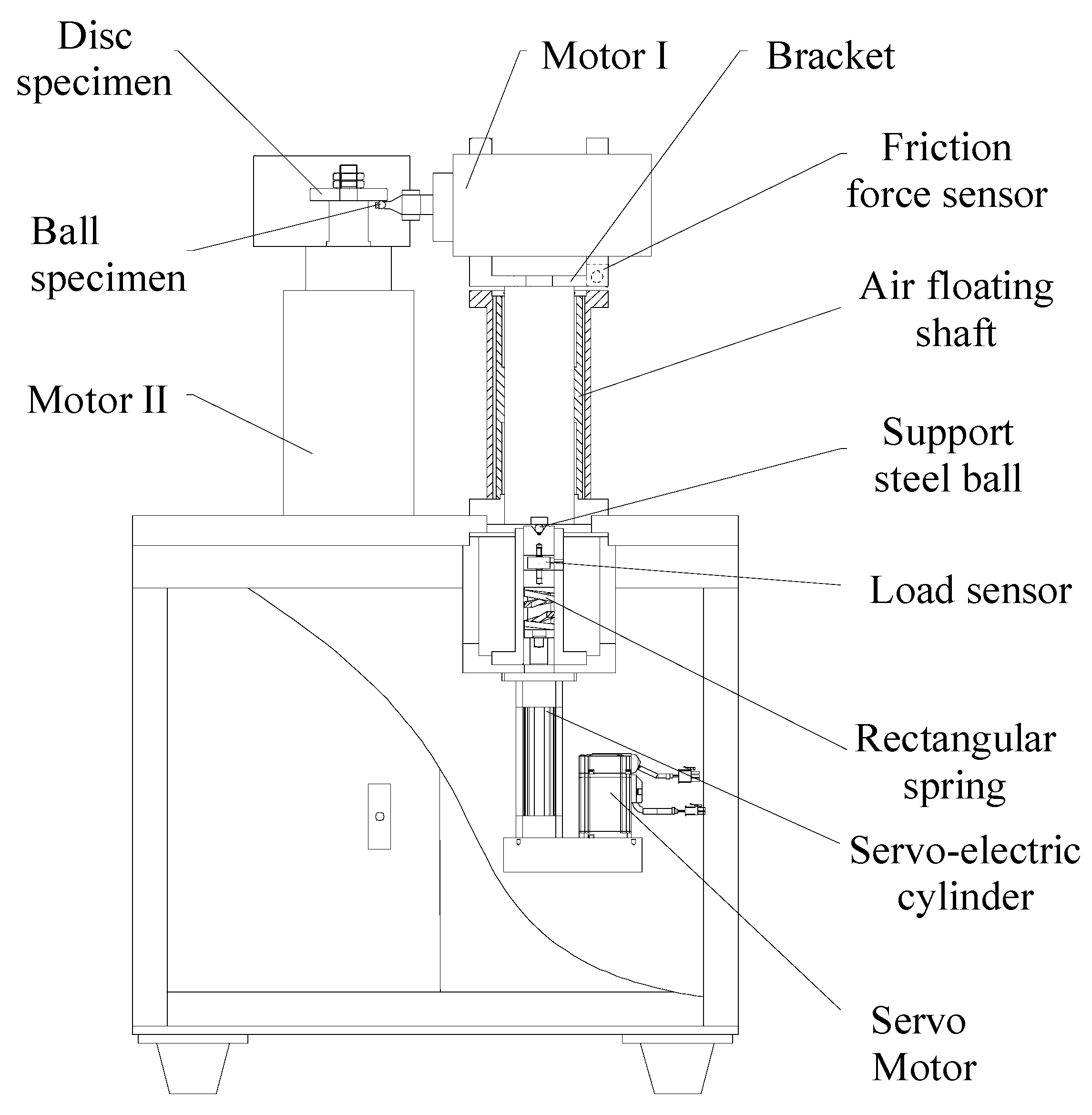
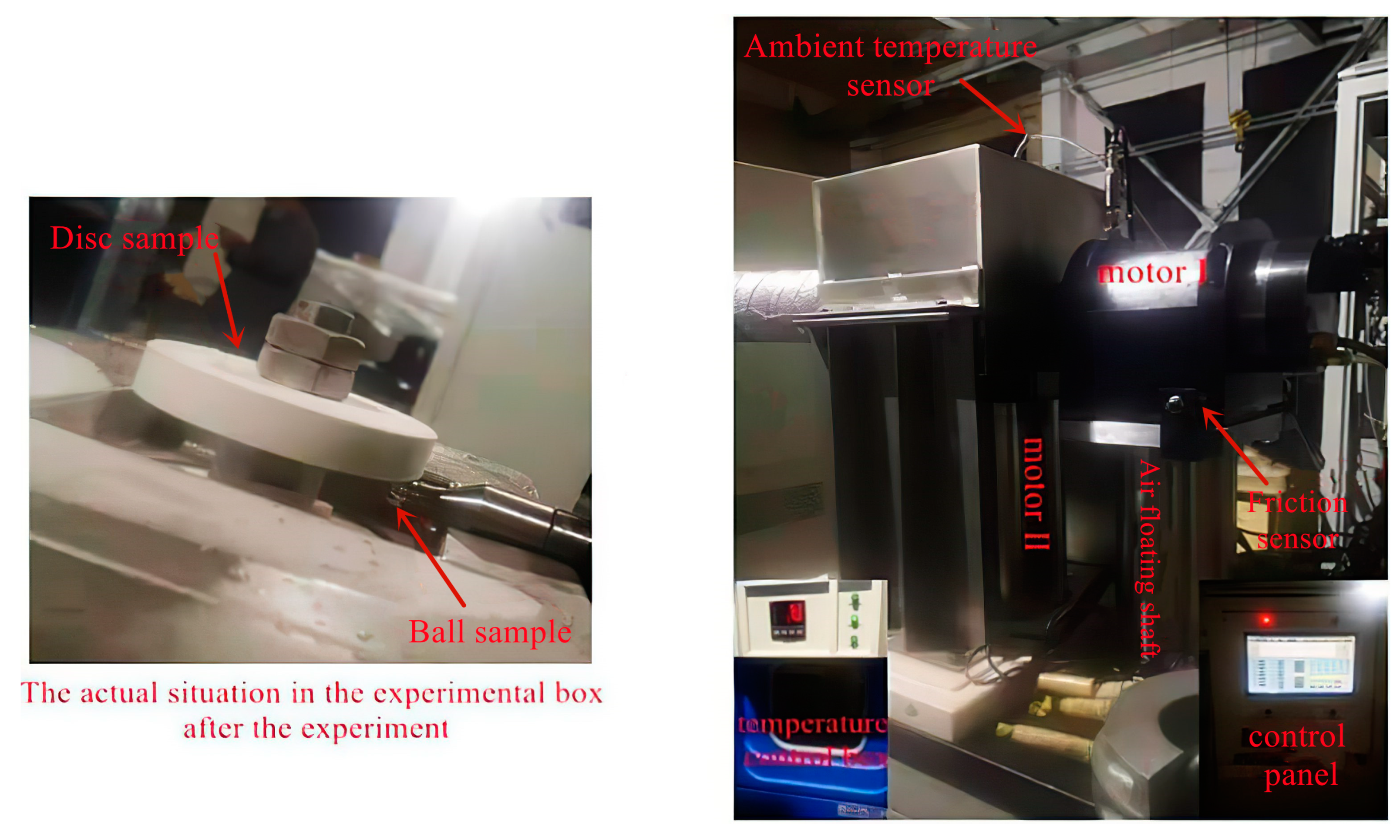
The main components of the cryogenic point contact sliding-rolling state friction tester are shown in Figure 2. This tester is mainly driven by two motors, and the ball specimen is fixed at the end of motor Ⅰ, which is positioned horizontally, and the disc specimen is fixed at the end of motor Ⅱ, which is positioned vertically. The axes of the two motors are co-planar, and their rotational speeds are controlled by two frequency converters. The two motors driving the ball and disc specimens were water-cooled to ensure operation within the appropriate temperature range. Motor II, driving the disc specimen, had a maximum speed of 24,000 RPM and was lubricated with grease. Motor Ⅰ, driving the ball specimen, had a maximum speed of 48,000 RPM and was lubricated with oil mist. The rotation speed of the two motors can meet the requirements of a high slide-to-roll ratio in the contact area of the ball and disc specimens. Table 2 lists the primary parameters of these two motors. A servo-electric cylinder is used for the loading of this tester. As shown in Figure 2, the servo-electric cylinder is installed at the bottom of the air-floating shaft axis. A rectangular spring and a load sensor are installed between the air-floating shaft and the servo-electric cylinder to cushion and measure the value of the loading force.
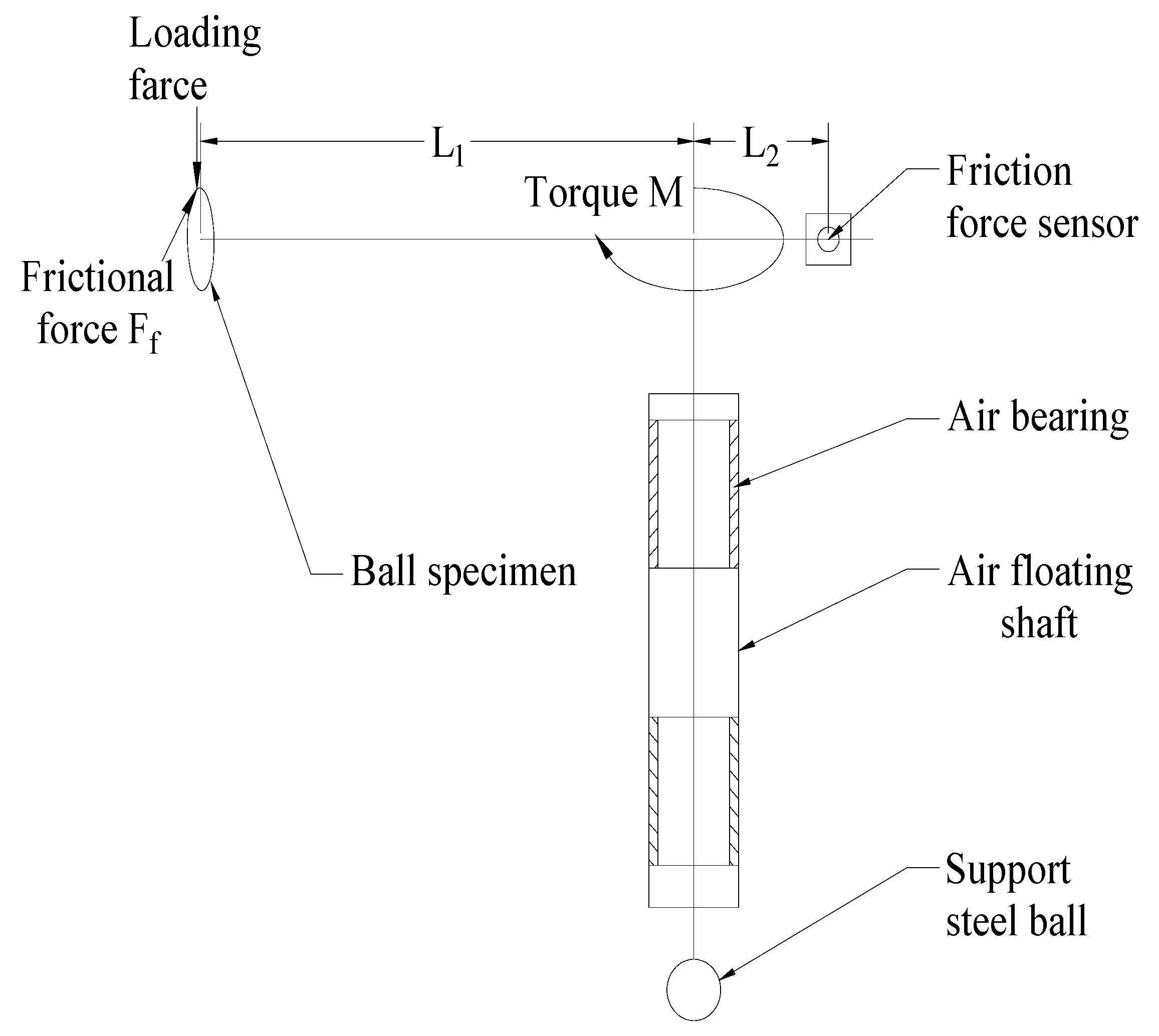
During the test, the servo motor controlled by PLC drives the servo-electric cylinder to move linearly and push the air bearing core upward to jack up the motor Ⅰ installed at the end of the air shaft to make the ball specimen contact with the disc specimen for the purpose of applying the load. The maximum normal load was 1500 N. The contact surface between the ball and the disc specimen deforms elastically under stress, extending the original point contact to a small radius circular contact surface. The frequency converter of the electric cylinder controls the value of the applied load. The friction force will be generated between the two contact surfaces if there exists relative sliding between the ball and disc specimens. Under the action of friction, the steel ball with motor Ⅰ and bracket deflects around the axis of the air-floating shaft, which compresses the friction force sensors fixed on the bracket. The actual value of the friction force is obtained from the test value of the sensor by lever conversion. Figure 3 shows the principle of friction force measurement. The friction force is calculated as:
Since the coefficient of friction of the air bearing rotation is very small, much smaller than that of the lubricant between the ball and the disc specimen, the accuracy of the test values can be ensured. A friction sensor is installed on each side of the bracket of motor Ⅰ, which can realize the measurement of the double-directional friction between the ball and disc specimens.
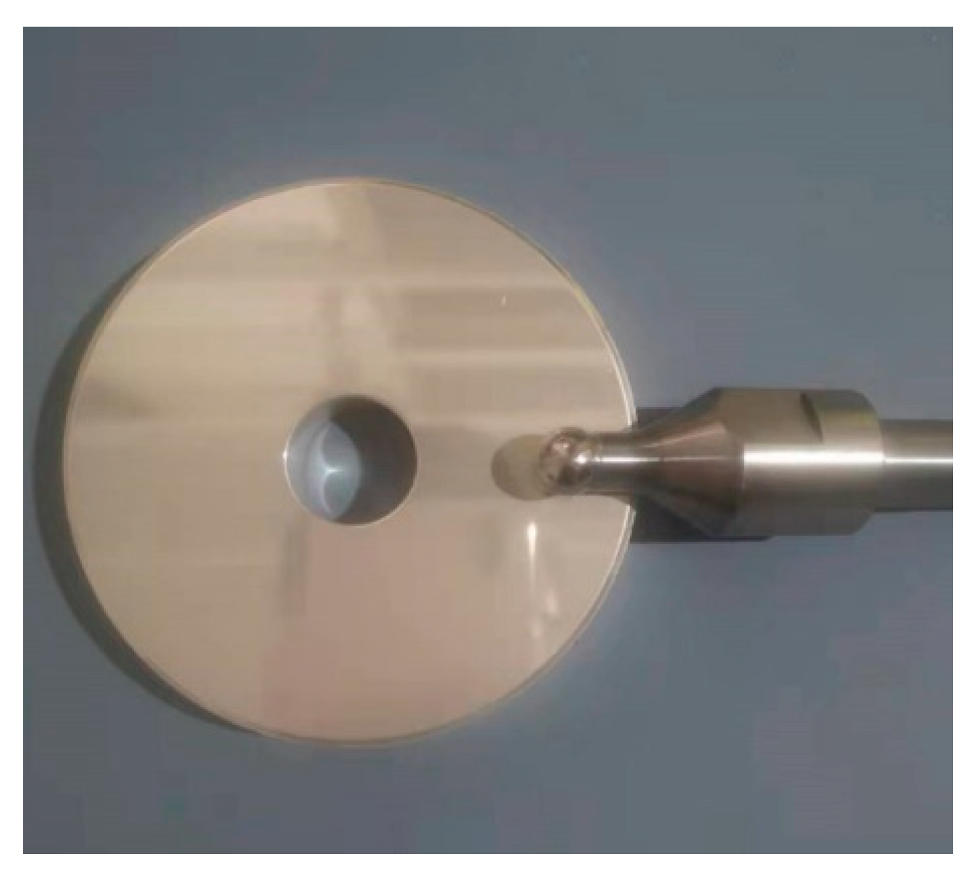
Many bearing lubricants work at linear speeds of up to 40 to 50 m/s. The speed and strength requirements of the tester in operation are considered to be the structural factors of the tester. The diameter of the disc specimen used in the design tester is 90 mm, the actual radius of the disc specimen used is 70–80 mm, and the ball specimen has three diameters of 10 mm, 19.05 mm, and 20.5 mm, which can be selected according to the actual situation of the experiment. Figure 4 shows the ball and disc specimens. The horizontal position of motor Ⅰ on the bracket can be adjusted appropriately so that the ball and disc are in contact at different radii to improve the utilization of the disc.
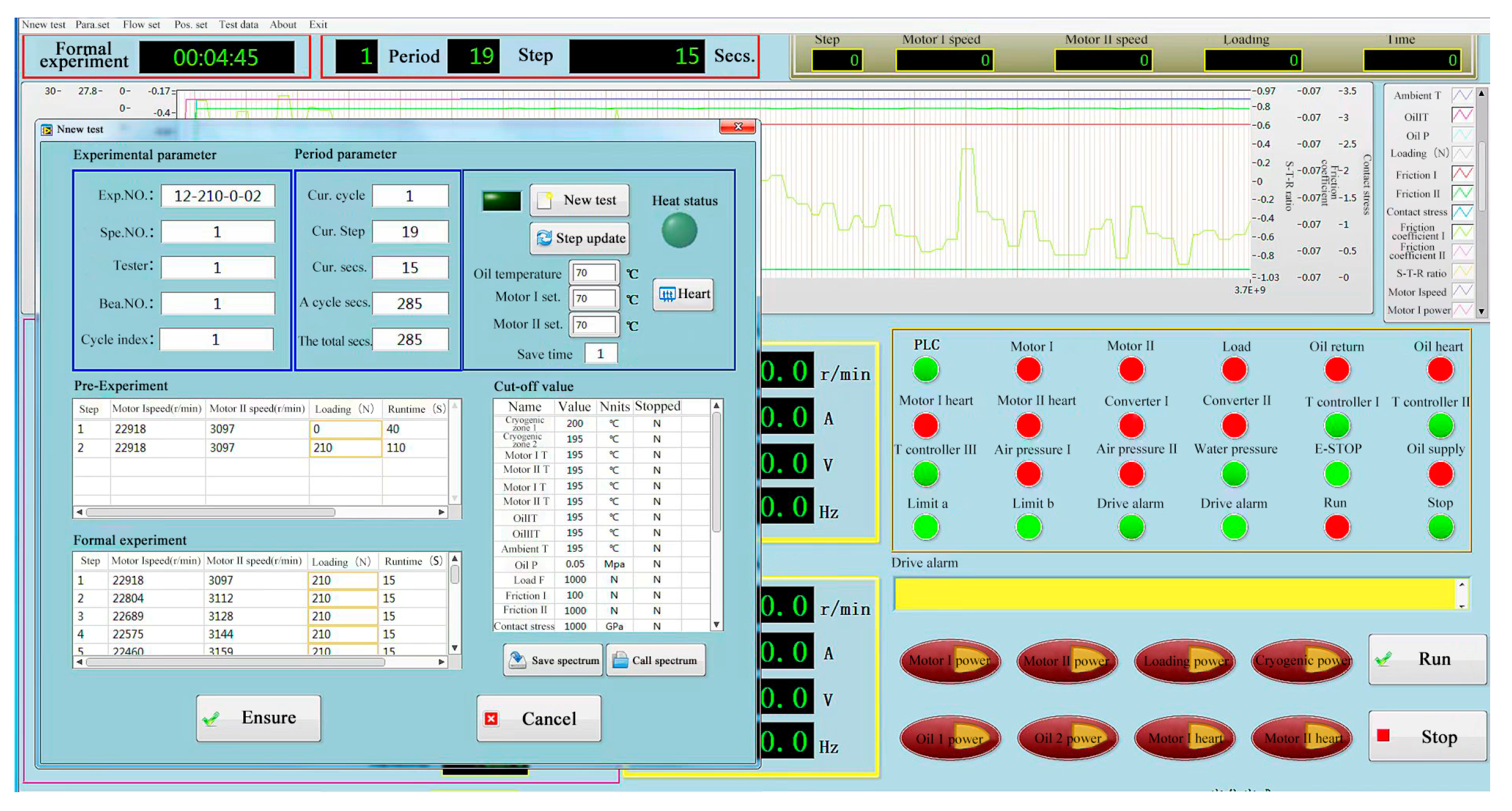
This tester has a complete electrical measurement and control system with high automation characteristics. Before the test, only load, temperature, motor speed, experiment time, and other relevant parameters need to be input to the corresponding position of the control panel. The tester can automatically complete the experimental test. The system can automatically record the load, temperature, friction, motor speed, slide-to-roll ratio, friction coefficient, and other parameters during the test. This tester can stop and alarm automatically when the motor current, speed, load, and temperature are overloaded to ensure the safety of the experiment. Figure 5 shows the computer control interface.
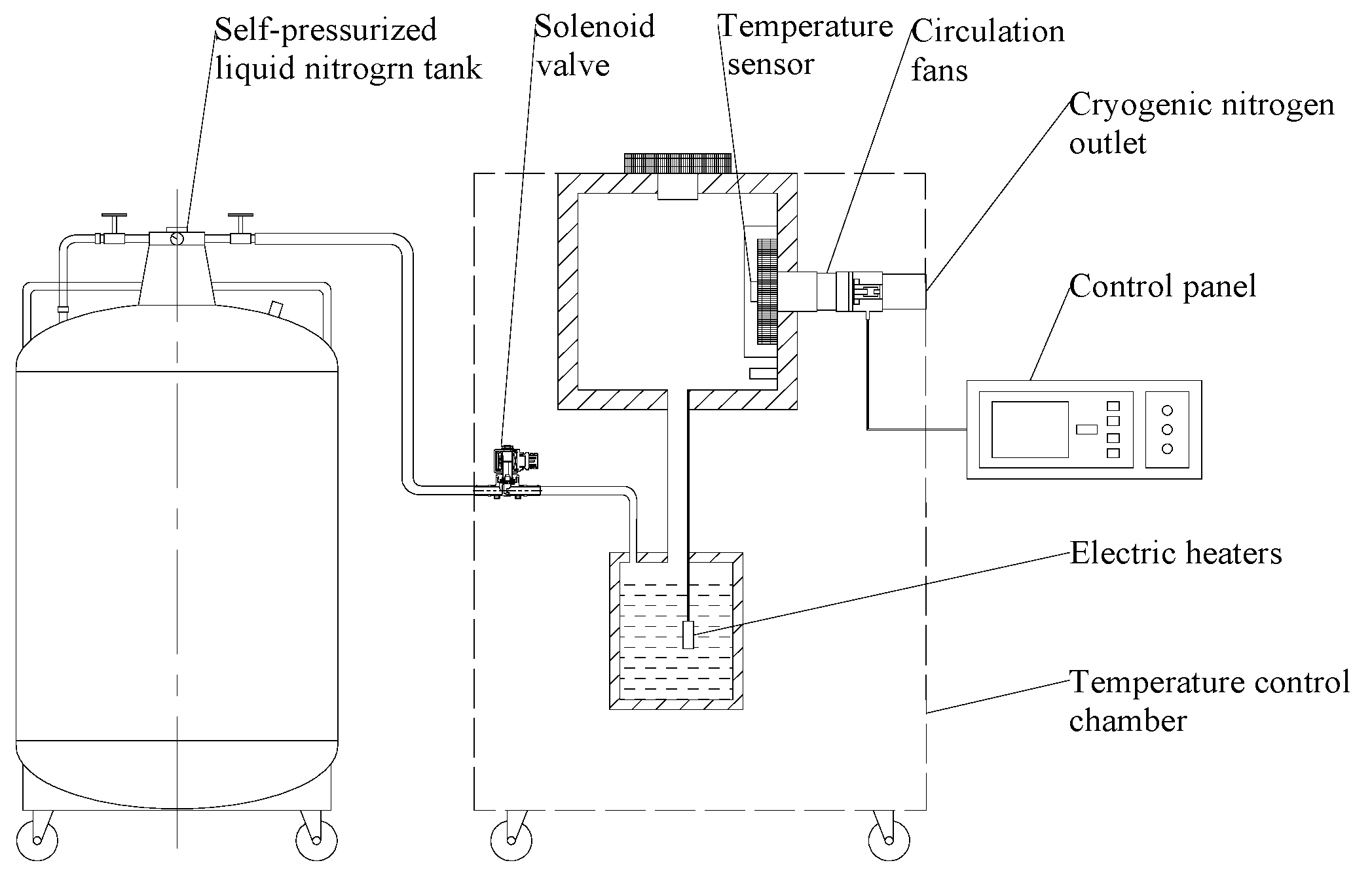
3.2. Cryogenic Environment System
The cryogenic environment system of this tester consists of a self-pressurized liquid nitrogen tank and a temperature control chamber. When testing the friction coefficient of cryogenic solid lubricants, the ambient temperature of the contact area of the ball and disc specimen needs to be lowered to room temperature ~−175 ℃.
Figure 6 illustrates the cryogenic environment system with a cooling origin provided by liquid nitrogen in a self-pressurized liquid nitrogen tank. During the experiment, the valve of the self-pressurized liquid nitrogen tank is opened, and the liquid nitrogen flows into the temperature-controlled chamber. The solenoid valve in the temperature-controlled chamber automatically controls the inflow of liquid nitrogen, and the electric heating wire heats the liquid nitrogen to the specified temperature of low-temperature nitrogen. Then, the low-temperature nitrogen is injected into the test box, thus reducing the ambient temperature. In addition, liquid nitrogen can be injected directly into the test chamber to achieve a lower temperature. The test box was filled with PTFE with good cold resistance and low thermal conductivity at the installation gap. The test shows that the ambient temperature of the experimental chamber can be stabilized at −175 ℃, which meets the requirements of the ambient temperature of the test area. The temperature control chamber adopts an ST590 temperature controller with advanced PID functions and high-temperature control precision.
4. The Friction Coefficient Test of PTFE-Coating and Ag-Coating in the Cryogenic Environment
The friction characteristics test of the solid lubricating material of cryogenic bearings is under the conditions of a given sliding speed and load . Under the conditions of testing, the friction force F between the steel ball and solid lubricating material disc specimen with time was found, along with the variation law of the friction coefficient μ of the solid lubricating material with time and the variation curve of the solid lubricating material friction coefficient μ with the sliding velocity.
Table 3 lists some test conditions and major parameters of the ball and disc specimens used in the friction coefficient tests of the PTFE coating and the Ag coating in a cryogenic environment. G95Cr18 [22] was selected as the ball specimen material because it was used to manufacture rolling bearings that are widely used in aviation and navigation fields. In the experiment, the sliding velocities between the ball and disc specimens were selected as 0.0m/s, 0.32m/s, 0.64m/s, 0.8m/s, 1.6m/s, 3.2m/s, 4.8m/s, and 6.4m/s. The rolling velocity was 15m/s.
Considering the slowness of electric cylinder loading, the ball and disc speeds were first brought to a pure rolling state before loading. When the required load was applied, the program automatically changed the rotational speed of the ball and disc to allow them to reach the corresponding sliding state for testing. The speed change of the two motors can be completed in a short time, which can ensure the small wear of the ball and disc specimens, reduce the systematic error of the test machine, and make the test results more accurate.
As shown in Table 3, for the PTFE coating friction coefficient test, 24 sets of test data were obtained for the coefficient of friction versus time under different contact stresses of 12 MPa, 16 MPa, 20 MPa, average rolling velocity = 15 m/s, and sliding velocity = 0–6.4 m/s working conditions. The friction coefficients at different sliding velocities were averaged to obtain three friction coefficient curves with respect to the sliding velocity. Similarly, for the Ag coating friction coefficient test, we conducted tests at 2 rolling velocities and 4 contact stresses and obtained 48 sets of friction coefficients versus time and 6 friction coefficients versus sliding velocity curves. Figure 6 shows the actual conditions of the tester after the low-temperature PTFE coating test. Figure 7 shows the actual conditions of the tester after the low-temperature PTFE coating test.
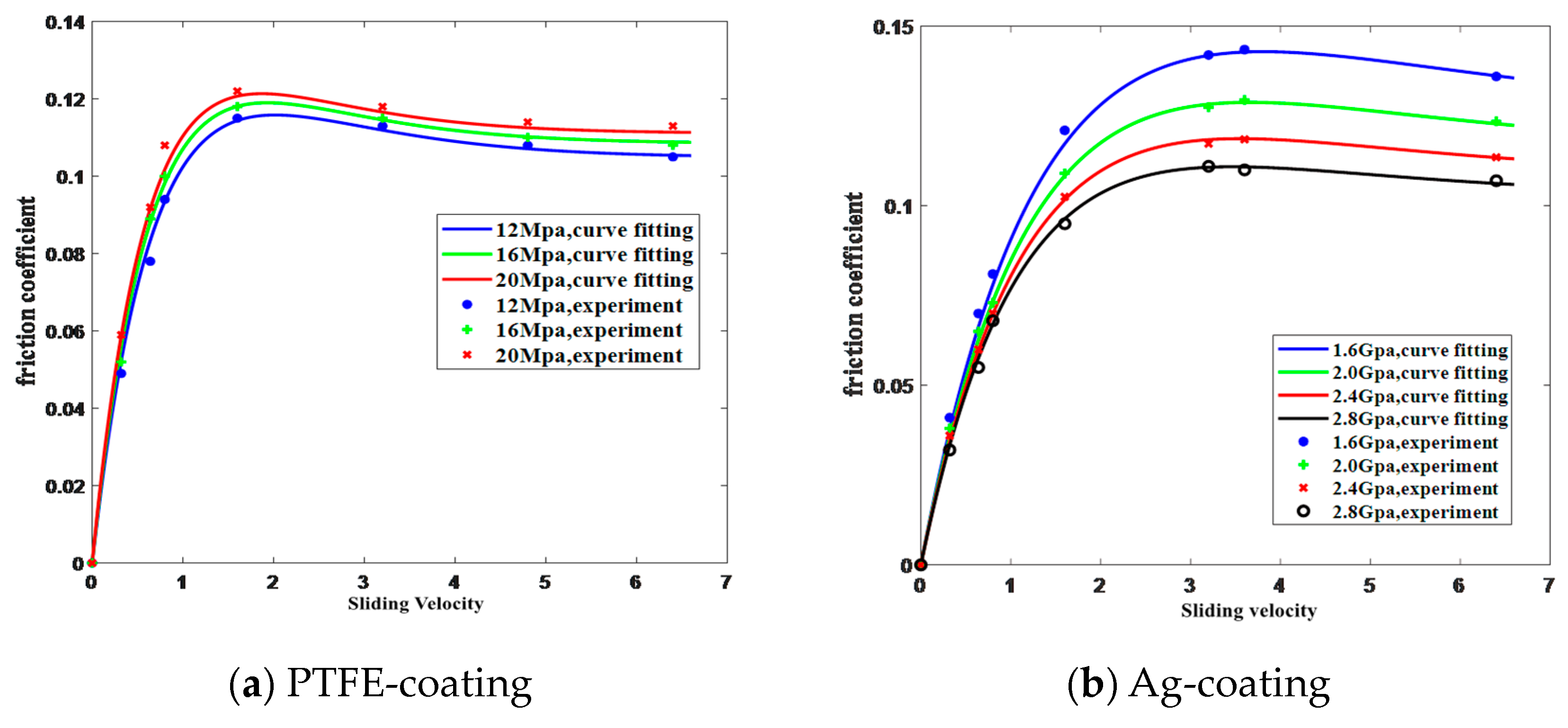
After the test, a friction coefficient model was used to fit the test data. According to Gupta [7], the friction coefficient can be expressed as a function of the sliding velocity, such that:
where is the friction coefficient, is the sliding velocity when the ball disc is in contact, and A, B, C, and D are the parameters to be fitted.
By analyzing Equation (9), when the sliding velocity is small, is approximately equal to 1, the equation can be approximated at , and the friction coefficient changes linearly with the sliding velocity . As the sliding velocity increases, the friction coefficient changes nonlinearly with the sliding velocity .
Figure 8 shows the fitted curves of Equation (9) under different testing conditions. There are high consistencies between the experimental data and fitted values, the relative error is generally within 5%, and the maximum error is no more than 10%. It is concluded that there is a higher accuracy when using Equation (9) to fit the friction coefficient of the PTFE coating and the Ag coating in cryogenic environment experimental data, which is suitable for engineering applications.
5. Conclusions
In this study, a cryogenic sliding-rolling contact tester was developed. This tester has a ball-on-disc design and can test the friction coefficient of cryogenic bearing lubricants in sliding-rolling contact conditions and achieve a test environment of −175 °C to room temperature. The air bearing is used to minimize the base friction of this tester and ensure the testing accuracy of the tester. The equipment was used to test the friction coefficients of PTFE coating and Ag coating, which are commonly used bearing lubricants in the cryogenic environment. The following conclusions were drawn:
(1) The ball-on-disc design simplifies the structure of the tester. This tester can be used with different specimen configurations, and users can use different materials of ball and disc specimens according to the experimental requirements. One of the ball specimens can have 3 different design radii. The specimens are driven independently by two motors, which can realize the simulation of the sliding-rolling contact state and conform to the actual running state of the bearings.
(2) This tester has an advanced electrical measurement and control system, which can realize complete automatic computer control.
(3) The friction forces of the PTFE coating and the Ag coating in a cryogenic environment (−175 ℃) were tested, and the curves of friction coefficient changes with sliding velocity were obtained. The results show that under low contact stress, the friction coefficient of the PTFE coating increases with the increase of contact stress. Under high contact stress, the friction coefficient of the Ag coating decreases with the increase of contact stress. Additionally, the friction curves agreed well with the Gupta sliding model.
Author Contributions
Conceptualization, F.L., B.S. and G.Z.; Data curation, F.L. and G.Z.; Formal analysis, F.L. and B.S.; Funding acquisition, W.Z.; Investigation, G.Z., F.L. and B.S.; Methodology, B.S. and W.Z.; Project administration, B.S. and W.Z.; Resources, B.S.; Supervision, W.Z. and B.S.; Writing—original draft, F.L. and B.S.; Writing—review & editing, B.S., W.Z. and J.R. All authors have read and agreed to the published version of the manuscript.
Funding
This research was funded by Youth Program of the National Natural Science Foundation of China (51905152).
Institutional Review Board Statement
Not applicable.
Informed Consent Statement
Not applicable.
Data Availability Statement
The data used to support the findings of this study are available from the corresponding author upon request.
Acknowledgments
The authors would like to thank Youth Program of the National Natural Science Foundation of China (51905152) for the financial support.
Conflicts of Interest
The authors declare no conflict of interest.
References
- Weng, L.J.; Liu, W.M.; Sun, J.Y.; Xue, Q.J. Opportunities and Challenges to Space Tribology. Tribology 2005, 25, 92–95. [Google Scholar]
- Servais, C.; Bizet, J.-L.; Kreit, P.; Guingo, S. Experimental Validation of a Thermal Model of a LOx Flooded Ball Bearing. Tribol. Int. 2014, 80, 71–75. [Google Scholar] [CrossRef]
- Burris, D.L.; Sawyer, W.G. A low friction and ultra low wear rate PTFE/PEEK composite. Wear 2006, 261, 410–418. [Google Scholar] [CrossRef]
- Burris, D.L. Investigation of the tribological behavior of polytetrafluoroethylene at cryogenic temperatures. Tribol. Trans. 2008, 51, 92–100. [Google Scholar] [CrossRef]
- Burris, D.L.; Sawyer, W.G. Addressing practical challenges of low friction coefficient measurements. Tribol. Lett. 2009, 35, 17–23. [Google Scholar] [CrossRef]
- Qian, J.; Miao, Y.; Qian, Y.; Fang, J.; Qiu, M. Tribological and mechanical properties tests of PTFE-based solid lubricating coatings. Bearing 2013, 10, 22–24. [Google Scholar]
- Gupta, P.K. Traction coefficients for some solid lubricants for rolling bearing dynamics modeling. Tribol. Trans. 2000, 43, 647–652. [Google Scholar] [CrossRef]
- Jo, J.H.; Rhim, Y.C.; Lee, S.; Kim, C.H. Development of Cryogenic Test Rig for Ball-Bearing and Evaluation of the Performance of the Prototype Ball-Bearing of Turbo pump. J. KSTL 2012, 28, 167–172. [Google Scholar]
- Choe, B.; Kwak, W.; Jeon, D.; Lee, Y. Experimental study on the dynamic behavior of ball bearing cage in cryogenic environments, Part I: Effects of cage guidance and pocket clearances. Mech. Syst. Signal Process. 2019, 115, 545–569. [Google Scholar] [CrossRef]
- Choe, B.; Kwak, W.; Jeon, D.; Lee, Y. Experimental study on dynamic behavior of ball bearing cage in cryogenic environments, Part II: Effects of cage mass imbalance. Mech. Syst. Signal Process. 2019, 116, 25–39. [Google Scholar] [CrossRef]
- Kwak, W.; Lee, J.; Lee, Y.B. A theoretical and experimental approach to ball-bearing frictional characteristics compared with cryogenic friction model and dry friction model. Mech. Syst. Signal Process. 2019, 124, 424–438. [Google Scholar] [CrossRef]
- Wang, J.; Wang, L.Q.; Zhang, F.; Peng, B. Development of the High-speed Sliding-rolling Contact Friction Testing Machine. Lubr. Eng. 2009, 34, 76–79. [Google Scholar]
- Ying, Y.Q.; Wang, L.Q.; Peng, B.; Zhang, C. Thermal Analysis of Tribo-parts under High-speed Sliding-rolling Contact. Lubr. Eng. 2011, 36, 6–9. [Google Scholar]
- Yang, B.Y.; Zheng, P.B.; Yang, R.P. Developmental Rig with Hydrostatic Bearing for Testing the EHD Traction Force of High-speed Lubricants. Tribotest J. 1998, 24, 31–38. [Google Scholar] [CrossRef]
- Wang, Y.S.; Deng, S.E.; Yang, B.Y. Development on the Lubricant Traction Measurement System. Lubr. Eng. 2008, 33, 89–91. [Google Scholar] [CrossRef]
- Wang, Y.S.; Yang, B.Y.; Wang, L.Q. The Study of Rheological Properties of Aviation Oil NO.4109. Lubr. Eng. 2005, 1, 55–58. [Google Scholar]
- Wang, Y.S.; Yang, B.Y.; Su, B.; Wang, L. Application of Elastic/Plastic Rheological Model in Characteristics Analysis of Elastohydrodynamic Lubrication of Grease. Tribology 2005, 25, 159–163. [Google Scholar]
- Wang, Y.S.; Deng, S.E.; Yang, H.S.; Su, B. Analysis for Traction Characteristics of HKD Aviation Lubricating Oil in Rolling/Sliding Contacts. Acta Armamentarii 2009, 30, 958–961. [Google Scholar]
- Wang, Y.S.; Cao, J.W.; Li, H.; Li, P. Study of Frictional and Viscositytemperature Characteristics of a Space Lubricating Oil No.4129 in Rolling/sliding Contact. Acta Armamentarii 2014, 35, 1515–1520. [Google Scholar]
- Su, B.; Lu, X.T.; Su, Z.H.; Yang, H.S. Research on Traction Characteristics of a Type of Grease for Lower-middle Speeds Bearing and Its Rheological Models. Lubr. Eng. 2018, 43, 36–40. [Google Scholar]
- Zhang, W.; Deng, S.; Chen, G.; Cui, Y. Impact of lubricant traction coefficient on cage’s dynamic characteristics in high-speed angular contact ball bearing. Chin. J. Aeronaut. 2017, 30, 827–835. [Google Scholar] [CrossRef] [Green Version]
- Guo, H.; Du, S.; Lei, J.; Zhang, Y.; Hu, L. Influence of Twin Carbide Structure on Friction and Wear Properties of G95Cr18 Stainless Bearing Steel. Sci. Lett. 2019, 6, 162. [Google Scholar] [CrossRef] [Green Version]
Figure 1.
Scheme of the tester.

Figure 2.
Main components of the tester.

Figure 3.
Friction measurement scheme.

Figure 4.
Ball and disc specimens.

Figure 5.
Computer control interface.

Figure 6.
Cryogenic environment system.

Figure 7.
Actual conditions of the tester after the low-temperature PTFE coating test.

Figure 8.
The fitting results of experimental data in a cryogenic environment.


Table 1.
Main parameters of the air shaft.
| Parameters | Numerical Value |
|---|---|
| Length of bearing L/mm | 100 |
| Diameter D/mm | 80 |
| Air supply pressure P/MPa | 0.5 |
| Ring width w/ mm | 0.5 |
| Ring surface air cavity thickness H/mm | 2 |
| Number of ring surfaces | 2 |
| Average film thickness h/mm | 0.01 |
Table 2.
Main parameters of the two motors.
| Main Parameters | Motor Ⅰ | Motor Ⅱ |
|---|---|---|
| Type | 120MD48Y5.8 | 150MD24Z7.5 |
| Normal power | 3.5KW | 7.5KW |
| Maximum speed | 48,000 RPM | 24,000 RPM |
| Type of cooling | Internal water cooling | Internal water cooling |
| Methods of lubrication | oil mist lubrication | Grease lubrication |
| Inverter type | VFD-B7.5 | VFD-B22 |
Table 3.
Test parameters of PTFE coating and Ag coating’s friction coefficient test in cryogenic environments.
Table 3.
Test parameters of PTFE coating and Ag coating’s friction coefficient test in cryogenic environments.
| Cryogenic PTFE Coating Friction Coefficient Test | Cryogenic Ag Coating Friction Coefficient Test | ||
| Test specimens Disc diameter [mm] Ball diameter [mm] Disc width [mm] Materials Disc and ball Coating material Coating thickness [mm] Test conditions Rolling velocity [m/s] Sliding velocity [m/s] Contact stress [MPa] Test temperature [℃] | 90 19.05 12 G95Cr18 PTFE 4–6 15 0–6.4 12,16,20 −175 | Test specimens Disc diameter [mm] Ball diameter [mm] Disc width [mm] Materials Disc and ball Coating material Coating thickness [mm] Test conditions Rolling velocity [m/s] Sliding velocity [m/s] Contact stress [GPa] Test temperature [℃] | 90 10 12 G95Cr18 Ag 4–6 15 0–6.4 1.6,2,2.4,2.8 −175 |
Publisher’s Note: MDPI stays neutral with regard to jurisdictional claims in published maps and institutional affiliations. |
© 2022 by the authors. Licensee MDPI, Basel, Switzerland. This article is an open access article distributed under the terms and conditions of the Creative Commons Attribution (CC BY) license (https://creativecommons.org/licenses/by/4.0/).
Share and Cite
MDPI and ACS Style
Liu, F.; Su, B.; Zhang, G.; Ren, J.; Zhang, W. Development of a Cryogenic Tester with Air Bearing to Test Sliding-Rolling Contact Friction. Lubricants 2022, 10, 119. https://0-doi-org.brum.beds.ac.uk/10.3390/lubricants10060119
AMA Style
Liu F, Su B, Zhang G, Ren J, Zhang W. Development of a Cryogenic Tester with Air Bearing to Test Sliding-Rolling Contact Friction. Lubricants. 2022; 10(6):119. https://0-doi-org.brum.beds.ac.uk/10.3390/lubricants10060119
Chicago/Turabian StyleLiu, Fengbo, Bing Su, Guangtao Zhang, Jiongli Ren, and Wenhu Zhang. 2022. "Development of a Cryogenic Tester with Air Bearing to Test Sliding-Rolling Contact Friction" Lubricants 10, no. 6: 119. https://0-doi-org.brum.beds.ac.uk/10.3390/lubricants10060119
Note that from the first issue of 2016, this journal uses article numbers instead of page numbers. See further details here.