Article

Influence of Compression Rings on the Dynamic Characteristics and Sealing Capacity of the Combustion Chamber in Diesel Engines

by
Brando Hernández-Comas
1,*,
Daniel Maestre-Cambronel
1,
Carlos Pardo-García
2,
Marlen Del Socorro Fonseca-Vigoya
3 and
Jhon Pabón-León
3
1
Programa de Ingeniería Mecánica, Universidad del Atlántico, Carrera 30 Número 8-49 Puerto Colombia, Atlántico 080001, Colombia
2
Programa de Ingeniería de Sistemas, Universidad Francisco de Paula Santander, Avenida Gran Colombia No. 12E-96 Barrio Colsag, San José de Cúcuta 540001, Colombia
3
Programa de Administración de Empresas, Universidad Francisco de Paula Santander, Avenida Gran Colombia No. 12E-96 Barrio Colsag, San José de Cúcuta 540001, Colombia
*
Author to whom correspondence should be addressed.
Submission received: 11 February 2021 / Revised: 23 February 2021 / Accepted: 26 February 2021 / Published: 2 March 2021
(This article belongs to the Special Issue Advances in Tribology and LCA Applied to Thermal Machines)

Abstract

:
Internal combustion engines are widely implemented in several applications; however, they still face significant challenges due to the sealing capacity of the compression rings. Gas leakage through the crankcase, also known as blow-by, directly impacts power losses, overall efficiency, and global emissions. Therefore, the present study investigates the influence of parameters such as the ring gap, ring masses, and twist angle of the compression rings on the sealing capacity of the combustion chamber. A mathematical model is proposed to account for geometric, dynamic, and operational characteristics in a single-cylinder diesel engine. The results indicated that the greatest gas losses to the crankcase occur during the compression and combustion stages as a consequence of extreme pressure conditions. Specifically, at least 0.5% of the gases locked in the combustion chamber are released on each cycle, while increasing the mass of the compression rings boosts the gas leakage due to higher inertial forces in the rings. In contrast, a positive twist angle of the compression rings reduced the combustion gases leakage by 7.33 × 10 5   g / cycle . Additionally, a combined reduction in the gap of both compression rings minimized the leakage flows by 37%. In conclusion, the proposed model served as a robust tool to evaluate different parameters on the sealing capacity of the combustion chamber that contribute to minimizing global emissions. Secondary piston motion and ring distortion represent significant opportunities in future studies.

1. Introduction

Internal combustion engines (ICE) have played a central role in socio-economic development worldwide due to versatile operations in various sectors. However, the adverse environmental impact associated with their operation set a pressing need to propose solutions to minimize the global warming potential. Therefore, both industry and academia are incorporating new technologies to mitigate the harmful effects caused by the operation of thermal machines [1]. For instance, the integration of waste heat recovery (WHR) systems [2] has emerged as a promising alternative to improve overall efficiency while minimizing fuel consumption and emissions levels. However, the techno-economic feasibility of this technology hinders its massive implementation, while in most cases, WHR systems are envisioned as long-term alternatives. Recently, governmental and international organizations have imposed strict legislative regulations to mitigate the overwhelming rate of fossil fuel consumption and greenhouse emissions [3]. Therefore, there is a significant necessity to propose short-term initiatives that positively impact the current challenges of ICEs [4,5]. Accordingly, as a first approach, reducing the sources of energy losses in ICEs stands as a suitable mechanism to favorably impact the environment and deaccelerate fossil fuel depletion. Different studies [1,5,6] have pointed out that nearly 15–20% of efficiency losses in the engine occur due to parasitic friction processes, and 50–60% occur due to thermal inefficiencies. Thus, in the last decade, extensive proposals have been made, namely control strategies, the deactivation of cylinders, variable valves, gear changes, biodiesel blends, and hydrogen doping, among others. The aforementioned strategies enable significant reductions in fuel consumption and emissions levels [7,8].
Particularly, the enhancement of combustion chamber design has gained increased attention since it represents a significant opportunity to minimize the emission index while improving the combustion performance [9,10]. Particularly, the piston compression rings in ICEs have a determinant role considering that their primary function is to hermetically seal the combustion chamber while preventing the leakage of combustion gases between the piston and the cylinder liner. As such, this component assists in inhibiting pressure losses in the chamber that negatively affect the energy efficiency of the engine. In this sense, an inadequate hermetic seal produces a high friction force, which promotes energy losses. In addition, the flexibility and thinness of the compression rings produce an elastodynamic behavior that reduces their sealing capacity [10]. In general, 3–5% of the total engine losses are associated with the interaction of the compression ring and the cylinder liner, and 2–7% of the losses are attributed to gas leakage in the chamber. Moreover, clearances in the compression rings promote non-combustion trapped gases that stimulate hydrocarbon emissions [11].
The geometric characteristics of compression rings foster significant flue gas leakage zones. In general, two main leakage areas can be identified, namely the compression ring gap and the clearance between the piston and the cylinder liner surface contact. This phenomenon of combustion gases leakage through the crankcase is usually referred to as blow-by gas. Consequently, these types of leaks deteriorate engine performance and lubrication and boost the overall emissions.
Considering the imminent relevance of combustion gas leakage to engine energy losses, various studies have been conducted to characterize the behavior of compression rings. Several experimental investigations have reported that inadequate lubrication at certain stages during the combustion process can be related to the interaction between the compression rings [12]. Namazian et al. [13] and Furuhama et al. [14] developed the first formulation for blow-by gas phenomena and showed the impact of axial ring movement on the tightness of the chamber. However, the analysis does not involve movement in other directions. Tomanik et al. [15] studied the influence of the separation between the compression ring and the cylinder wall, concluding that the reduction of this separation minimizes the gas leakage flow. However, the effect on secondary piston motion was not described. Wannatong et al. [16] and Keribar et al. [17] investigated the effects of surface properties and lubrication behavior. Przesmitzki et al. [18] and Lijima et al. [19] analyzed the radial movement of the compression ring, which involves the study of the detachment phenomenon between the cylinder liner and the face of the ring. The findings demonstrated that increasing both the engine speed and load reduces the radial contact on the underside of the ring.
Due to the difficulty of experimental studies, research using simulation methods has been predominantly chosen to study piston rings. For instance, Baker et al. [11] implemented a three-dimensional elastic-dynamic ring model to improve numerical predictions. The study proved that ring dynamics significantly affect the degradation and consumption of lubrication oil, the wear on the cylinder liner and the rings, the friction force, and the polluting products of combustion. Tian [20] investigated the effect of gas leaks on compression ring lubrication and oil transport using a finite element model. The outcomes pointed out that ring dynamics affect the tribological behavior of the contact between the piston and the cylinder liner. In the same vein, Turnbull et al. [9] investigated the influence of ring curvature under different operating conditions using finite element analysis (FEA). In this study, the proposed model proved to be consistent with experimental measurements of excitation sweep with a maximum relative error of 11%.
Previous research shows that compression ring sealing capacity represents a significant source of energy loss and fosters emissions levels in the engine. Therefore, the development of analyses that involve dynamic behavior, tribological characteristics, and gas leakage conditions in these types of elements can improve energy efficiency and reduce the environmental impact of ICEs. So far, systematic approaches and numerical methodologies have been proposed to evaluate the sealing capacity of compression rings; however, since some simplifications are incorporated into the models, it establishes a pressing need to provide a broader perspective of the blow-by phenomena by the simultaneous consideration of different parameters involved in the sealing performance.
The main contribution of this investigation is to evaluate the combined effects of different design parameters of compression rings on the sealing capacity of the combustion chamber. Accordingly, a sensitivity analysis is incorporated to unravel the impact of variations in the ring gap, ring masses, and twist angle, which further expands the research focused on short-term alternatives to reduce energy losses and emissions levels in ICEs. A mathematical model is proposed to integrate the lubricating oil properties, the kinematics of the piston, the kinetics of the rings, and the piston deformation into the blow-by phenomena. The geometric and operational characteristics are based on a single-cylinder diesel test engine. Incorporating the second compression ring into the proposed model is a remarkable aspect that is generally disregarded in former research. Therefore, the present work contributes to close the knowledge gap related to the sealing capacity of compression rings while elucidating the effects of geometrical, operational, and dynamic characteristics on the overall performance. The investigation is structured as follows: Section 2 exposes the main features of the proposed mathematical formulation that describe the performance of the compression rings on the sealing capacity. Moreover, this section pinpoints the characteristics of the sensitivity analysis, the simulation considerations, and the experimental validation of the model. Afterward, Section 3 exhibits the main outcomes and provides critical discussions. Lastly, Section 4 provides the concluding remarks, limitations, and future avenues in the subject.

2. Materials and Methods

2.1. Mathematical Model of the Compression Ring

2.1.1. Lubrication Oil Properties

This section aims to characterize the lubrication oil properties in the analysis of the compression rings. The latter is relevant considering that both the temperature and pressure have a predominant influence on the overall behavior of the lubricating oil density. Therefore, the study incorporates an empirical formulation that has been proposed in similar applications [21,22]. The expression is defined as follows:
ρ = ρ ο ( 1 β · [ T T o ] ) + 6 × 10 10 · ρ o · ( P P a t m ) 1 + 1.7 × 10 9 · ( P P a t m )
where the variables T and P represent the temperature and pressure, respectively. The subscript “ o ” represents the reference environmental conditions. β accounts for the coefficient of thermal expansion of the lubricating oil.
On the other hand, Roeland and Houpert [23,24] introduced another expression to relate the viscosity of the lubricating oil in terms of the pressure and temperature as defined in Equation (2).
η = η o · e x p ( [ l n ( η o ) + 9.67 ] · [ ( T 138 T o 138 ) S o · ( 1 + P P a t m 1.98 × 10 8 ) Z 1 ] )
where η o represent the viscosity of the lubricant at ambient conditions. The variables S o and Z are calculated using Equations (3) and (4), respectively.
S o = β o · ( T o 138 ) l n ( η o η )
Z = α o · c p l n ( η o η )
where Z and S o represent the piezo-viscosity and thermo-viscosity indices, respectively. c p and η are constant values defined as 1.98 × 10⁸ Pa and 6.31 × 10 5 Pa · s. β o and α o are the thermo-viscosity coefficient and atmospheric piezo-viscosity, respectively.

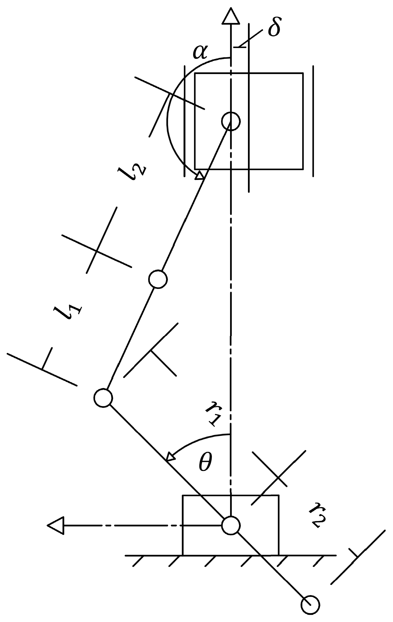
2.1.2. Kinematic Piston Model

Figure 1 shows the schematics of the piston mechanism considered in the analysis. The aim of this section is to characterize the primary motion of the piston during the combustion cycle that further assists in evaluating the overall behavior of the compression rings. The main consideration in the model establishes that the piston rod–crankshaft structure operates as a sliding mechanism to calculate operational parameters such as velocity, displacement, and acceleration in terms of the crankshaft angle [25].
From Figure 1, a relationship is made between the length of the connecting rod ( l r = l 1 + l 2 ) and the crankshaft ( l c = r 1 + r 2 ) , which is shown in Equation (5).
l r · s i n α = l c · s i n θ + δ
where α refers to the displacement angle of the connecting rod, θ represents the displacement angle of the crankshaft, and δ is the distance between the wrist pin and the axis of the piston, respectively. By performing the first and second derivatives of Equation (5), the following equations are obtained:
α ˙ = l c · θ ˙ · c o s θ l r · c o s α
α ¨ = θ ˙ 2 · [ ( l c · c o s θ l r · c o s α ) 2 · t a n φ l c · s i n θ l r · c o s α ] + θ ¨ l c · c o s θ l r · c o s α
To describe the acceleration of the center of mass of the piston ( y ¨ p ) , connecting rod ( x ¨ r , y ¨ r ) and crankshaft ( x ¨ c , y ¨ c ) , Equations (8)–(12) are used [26].
Piston:
y ¨ p = θ ¨ · ( l c · c o s θ · t a n α l c · s i n θ ) + θ ˙ 2 · [ l c 2 · c o s 2 θ l r · c o s 3 α l c · s i n θ · t a n α l c · c o s θ ]
Connecting rod:
x ¨ r = l c · ( 1 l 1 l 2 ) · θ ¨ · c o s θ + l c · ( 1 l 1 l 2 ) · θ ˙ 2 · s i n θ
y ¨ r = θ ¨ · ( l c · l 1 l 2 · c o s θ · t a n α l c · s i n θ ) + θ ˙ 2 · ( l 1 l 2 · l c 2 · c o s 2 θ l r · c o s 3 α l 1 l 2 · l c · s i n θ · t a n α l c · c o s θ )
Crankshaft:
x ¨ c = θ ¨ · r 2 · c o s θ θ ˙ 2 · r 2 · s i n θ
y ¨ c = θ ¨ · r 2 · s i n θ + θ ˙ 2 · r 2 · c o s θ

2.1.3. Compression Ring Kinematics

The compression rings of the piston are subjected to two types of movement, namely radial and axial motion. Therefore, two dynamic expressions are derived to describe the behavior of the rings.
Accordingly, Equations (13) and (14) describe the dynamic behavior for radial and axial movement, respectively [16].
m r x ¨ = F g , x + F h c , x + F h v , x + F a c , x + F a v , x + F c , x
m r y ¨ = F g , y + F h c , y + F h v , y + F a c , y + F a v , y + F c , y
where the subscript g indicates the force produced by the combustion gases, and h c and h v represent the hydrodynamic friction due to contact and viscous effects, respectively. Similarly, the subscripts a c and a v accounts for the asperity force due to contact and viscous effects, respectively. Lastly, the subscript c relates to the compression force due to ring installation.
The combustion gas force ( F g ) is determined via Equation (15).
F g = P g · A
where P g relates to the pressure of the combustion gases.
The hydrodynamic friction force due to contact ( F h c ) and the viscous effects ( F h v ) of the lubricating oil are calculated using Equations (16) and (17), respectively.
F h c = P h · A
F h v = τ · A
where P h denotes the hydrodynamic pressure associated with the lubricant, τ constitutes the viscous shear stress of the lubricant, and A relates the sectional area. Since the dynamic conditions in the compression ring do not correspond to a linear behavior, the pressure produced by the lubricating oil is not uniform. Therefore, the Reynolds hydrodynamic lubrication model is introduced to determine the hydrodynamic pressure [27,28], as shown in Equation (18).
x ( ϕ x h 3 P h x ) + y ( ϕ y h 3 P h y ) = 6 η · v p ( h y + σ s ϕ s y ) + 12 η h t
where ϕ x and ϕ y refer to the pressure–flow factors in the axial coordinates, and ϕ s accounts for the shear flow factor. The viscous shear stress ( τ ) is calculated via Equation (19).
τ = ϕ s p · h 2 · d P h d y ( ϕ s s + ϕ s r ) · η · v p h
where ϕ s p , ϕ s s , ϕ s r are the shear factor due to mean pressure, sliding velocity, and local roughness, respectively.
The asperity force due to contact ( F a c ) and the viscous effects ( F a v ) of the lubricating oil is calculated using Equations (20) and (21), respectively.
F a c = ζ · P a · A
F a v = τ o · A e · A
where ζ represents the asperity shear strength coefficient. τ o indicates the limiting Eyring shear stress of the lubricant and A e relates to the effective asperity contact area. P a is the asperity contact pressure, calculated from Equation (22) [29].
P a = 16 π 2 15 · ( σ s β a ) 1 2   · λ · F 5 / 2 ( λ ) · E · ( σ s · β a · ξ ) 2 ,     λ = h σ s
where σ s is the surface roughness, β a refers to the average asperity radius of curvature, ξ relates the asperity distribution per unit contact area, λ accounts for the Stribeck’s lubricant film ratio, E denotes the equivalent Young’s modulus of elasticity, h express the lubrication film thickness and F 5 / 2 represents a statistical function of lubrication film ratio. The latter is approximated by a fifth-order polynomial as shown in Equation (23) [30].
F 5 / 2 ( λ ) = { 0.0046 λ 5 + 0.0574 λ 4 0.2958 λ 3 + 0.7844 λ 2 1.0776 λ + 0.6167 ;     λ 2.224 0 ;     λ > 2.224 }  
The equivalent Young’s modulus of elasticity ( E ) is determined from Equation (24).
1 E = 1 v r i n g 2 E r i n g + 1 v c y l i n d e r 2 E c y l i n d e r
where   v and E relate to the Poisson’s ratio and elasticity modulus, respectively. The subscripts “ring” and “cylinder” refer to the compression ring and cylinder liner, respectively.
The lubrication film thickness is calculated via Equation (25).
h = e t · c o s α + c c p + y L p s · c o s α · ( e b e t ) + δ
where e t is the eccentricity of the piston at the top of the skirt, e b is the eccentricity of the piston at the bottom of the skirt, c c p is the clearance between the cylinder liner and the piston skirt, and L p s is the longitude of the piston skirt. The parameter δ represents the deformation of the piston due to the pressure of the lubrication film, which is calculated as described in Section 2.1.6.
Subsequently, the effective asperity contact area ( A e ) is calculated via Equation (26).
A e = π 2 · ( σ s · β · ξ ) 2 · F 2 ( λ ) · A
where F 2 ( λ ) represents a statistical function of Stribeck’s lubricant film ratio, which is calculated as shown in Equation (27) [30].
F 2 ( λ ) = { 0.0018 λ 5 + 0.0281 λ 4 0.1728 λ 3 + 0.5258 λ 2 0.8043 λ + 0.5003 ;     λ 2.295 0 ;     λ > 2.295 }  
Installing the ring on the piston produces a compression force ( F c ) on the ring body. This force is calculated using Equation (28) [31].
F c = P k · A
where P k is the specific pressure of the piston ring on the cylinder wall, which is determined by means of Equation (29).
P k = σ b · b 2 3 D · ( D b )
where D and b are the diameter and width of the compression ring, respectively. σ b is the bending stress, calculated as shown in Equation (30).
σ b = 3 E r i n g · b · f 2 L r p 2
where f is the ring gap at free condition and L r p is the length of the ring.
The moment ( M c ) produced by the compression force ( F c ) is calculated by Equation (31).
M c = T t · ( ψ ψ o )
where ψ and ψ o are the ring twist angle in operating and static conditions. T t is the stiffness torsion of the ring, calculated as shown in Equation (32) [32].
T t = b 3 · E r i n g · l n ( D o D i ) 3 ( D o + D i )
where D i and D o are the inner and outer diameter of the compression ring.

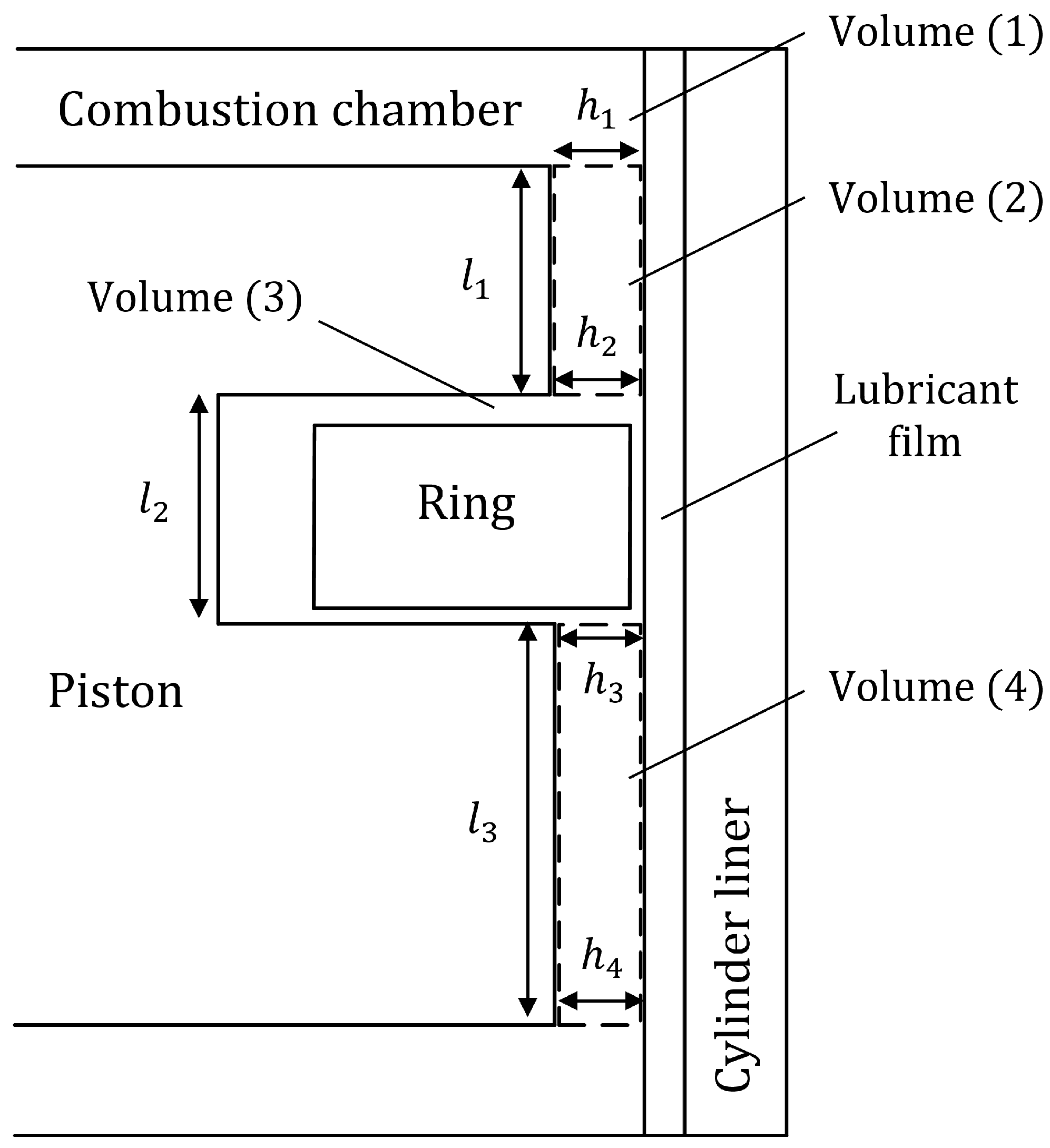
2.1.4. Gas Blow-By Model

The thermal flow control volume methodology proposed by Baker et al. [11] is implemented in the study to determine the mass flow of combustion gases that escape through the piston grooves. Figure 2 describes the control volumes analyzed in this model.
The pressure induced by the combustion gases in the compression ring directly affects the trapped gases shown in the control volume (2). The mass flow in this volume was modeled considering an isothermal flow that follows the laminar regime. This consideration agrees with the experimental study performed by Namazian and Heywood [13]. Notice that the model considers the impact of the lubricating oil on the sealing capacity according to the lubricating film thickness, which is calculated from Equation (25) based on operational and geometrical parameters [33]. Moreover, the mass flow in the control volume (1) is calculated by Equation (33) [34,35].
m ˙ 1 = A 1 · h 1 2 · ( P 3 2 P 1 2 ) 24 l 1 · n g · R · T
where m ˙ 1 relates to the mass flow rate between the control volume (1) and (3). The geometric parameters L 1 , h 1 and A 1 represent the length, width, and area of the section normal to the mass flow. T is the temperature of the combustion gases, R refers to the ideal gas constant, n g denotes the dynamic viscosity of the gas, and P 3 and P 1 represent the pressure in the control volume (3) and (1), respectively.
The dynamic viscosity of the combustion gases ( n g ) is obtained via Equation (34).
n g = n o · ( T o + S n ) · T 3 / 2 ( T + S n ) · T o 3 / 2 ·
where n o and T o relate to the dynamic viscosity and temperature of the gas under reference conditions [36]. S n is the Sutherland’s number.
The mass flow between the control volume (2) and (4) is calculated as an isentropic flow through an equivalent hole [37].
m ˙ 2 = c d · a g · P 3 · f m ( R · T ) 1 / 2
where a g is the ring gap area, c d is the discharge coefficient and f m is the compressibility factor. The parameter f m depends on the pressure P 3 and P 4 , which corresponds to the pressure in the control volume (3) and (4), respectively. The calculation of f m is determined by Equation (36) [16].
f m = { ( P 4 P 3 ) 1 / γ s · ( [ ( 2 γ s γ s + 1 ) ( γ s + 1 ) / 2 ( γ s + 1 ) ] · [ 1 ( P 4 P 3 ) ( γ s 1 ) / γ s ] ) 1 / 2 ,     P 4 P 3 > ( 2 γ s + 1 ) γ s / ( γ s 1 ) γ s 1 / 2 · ( 2 γ s + 1 ) ( γ s + 1 ) / 2 ( γ s + 1 ) ,     P 4 P 3 ( 2 γ s + 1 ) γ s / ( γ s 1 ) }
where γ s is the specific heat ratio. The discharge coefficient ( c d ) is calculated by Equation (37).
c d = 0.85 0.25 · ( P 4 P 3 ) 2

2.1.5. Compression Ring Deformation Model

The characterization of the deformation process in the piston ring follows the methodology proposed by Lang [35], which is derived from the deformation motion in curved beams. This formulation is shown in Equations (38) and (39).
E r i n g · A r R r 2 · ( u + w φ ) E r i n g · I r R r 4 · ( 3 w φ 3 + 4 u φ 4 ) = ρ r · A r · 2 u t 2 F t , r
E r i n g · A r R r 2 · ( u φ + 2 w φ 2 ) + E r i n g · I r R r 4 · ( 2 w φ 2 + 3 u φ 3 ) = ρ r · A r · 2 w t 2 F t , a
where I r and A r relate to the second moment of inertia and the cross-sectional area of the ring, respectively. R r denotes the curvature radius of the ring, φ refers to the angular position of the circumference of the ring, F t , r is the force total radial and F t , a is the total axial force. u and w represent the radial and axial direction, respectively.

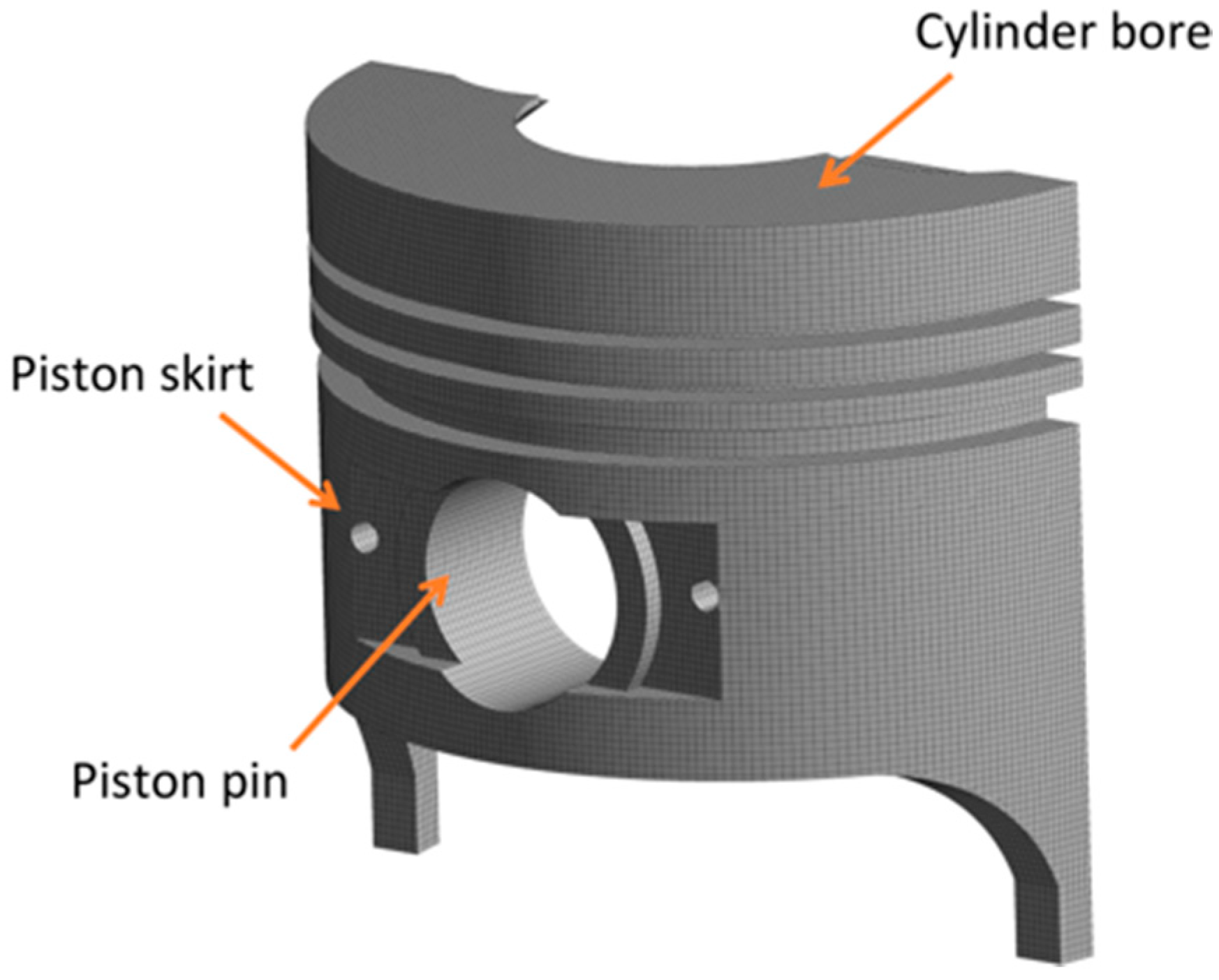
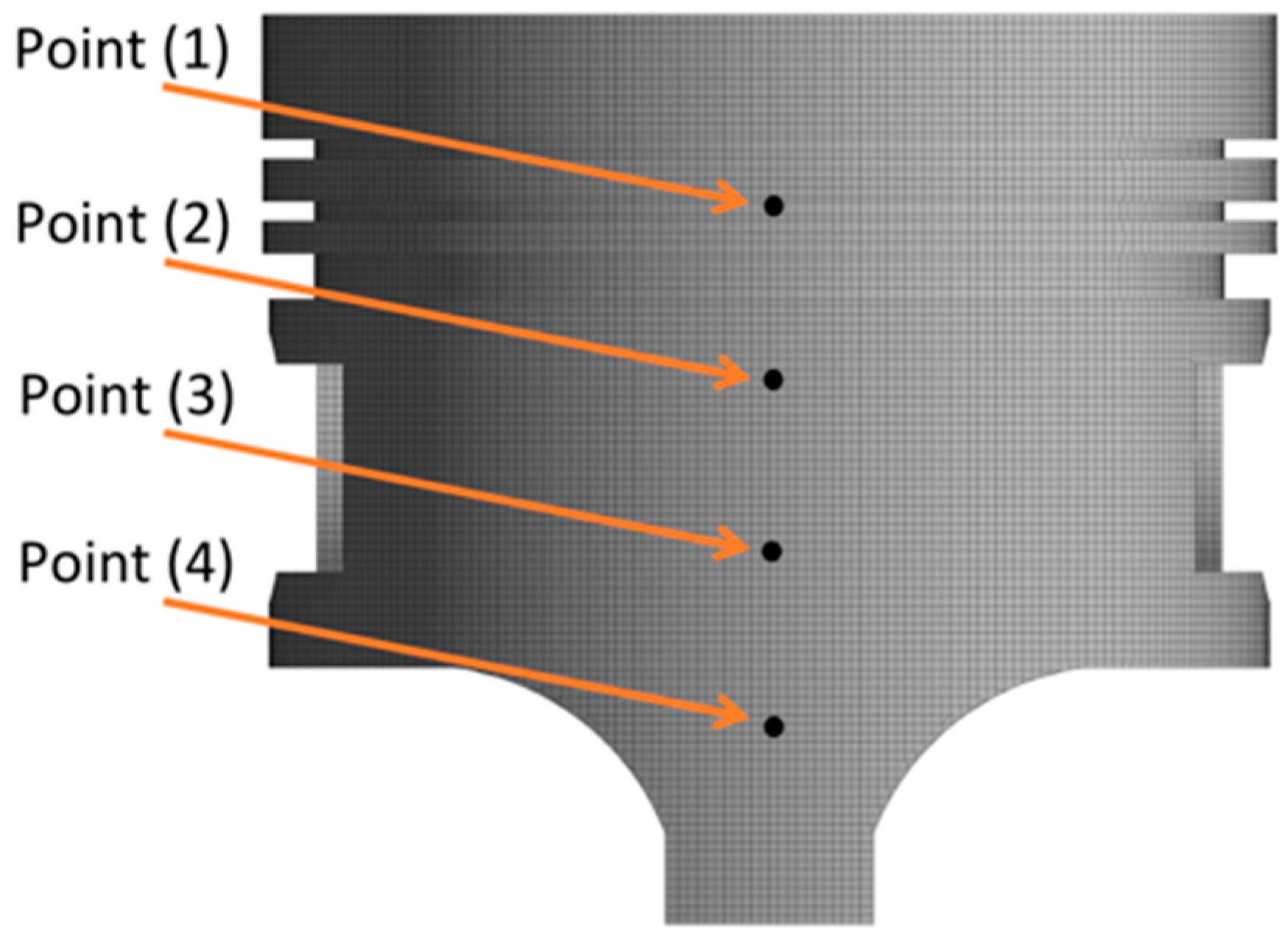
2.1.6. Piston Skirt Deformation Model

The deformation of the piston skirt ( δ ) influences the thickness of the lubrication film as shown in Equation (25), which directly impacts the dynamic conditions of the compression ring since it is associated with the roughness contact pressure and hydrodynamic pressure. Therefore, incorporating this parameter into the model is vital to predicting the compression ring sealing capacity accurately. For the calculation, a compliance matrix is generated through a symmetric finite element model (FEM), as shown in Figure 3.
From the matrix shown in Figure 3, the piston deformation induced by the lubricating oil pressure is calculated. The construction of the matrix constitutes a hexahedral mesh type composed of 360,000 elements and 385,000 nodes. The mesh generation conditions are in accordance with previous investigations [38,39]. Accordingly, the deformation of the piston skirt is determined using Equation (40).
δ = [ C i j θ y ] · ( P h + P a )
where C i j represents the elastic compliance matrix that relates to the movement of each node (i, j). P h and P a refer to the hydrodynamic pressure and the asperity contact pressure, which are calculated using Equations (18) and (22), respectively. To confirm the consistency within the calculations, a mesh independence analysis is carried out while comparing the results at different locations on the piston skirt, as shown in Figure 4. Accordingly, Figure 5 depicts the mesh independence analysis evaluation.
According to Figure 5, a total of 360,000 elements guarantees a relative difference of less than 2.8% in the deformation estimates. As such, this value is set for the number of computational domain elements, which also enables a reasonable convergence time.

2.2. Numerical Methodology

Since the present study investigates the influence of different design parameters of the first and second piston rings on their dynamic characteristics and sealing capacity, a sensitivity analysis is established by introducing parameter modifications as indicated in Table 1.
Where G i and m i are the gap and mass in the reference conditions of the compression rings. The positive and negative twist angle characteristics are described in Figure 6.
Where ID and OD are inner and outer diameter, respectively. Figure 7 displays the cross-section of the engine piston rings. Specifically, the first ring possesses a barrel curve-shaped geometric profile, the second ring has a tapered face profile, and the third ring presents a beveled edge profile.
The solver ode45 from Matlab® software was implemented to solve the model equations proposed in Section 2.1. For the simulations, the characteristics of a single-cylinder diesel engine were used as a reference. The technical specifications of the engine are listed in Table 2. The simulation was executed at a rotation velocity of 3600 rpm and a torque of 9 Nm since this is the engine’s main operating condition (maximum efficiency operating zone).

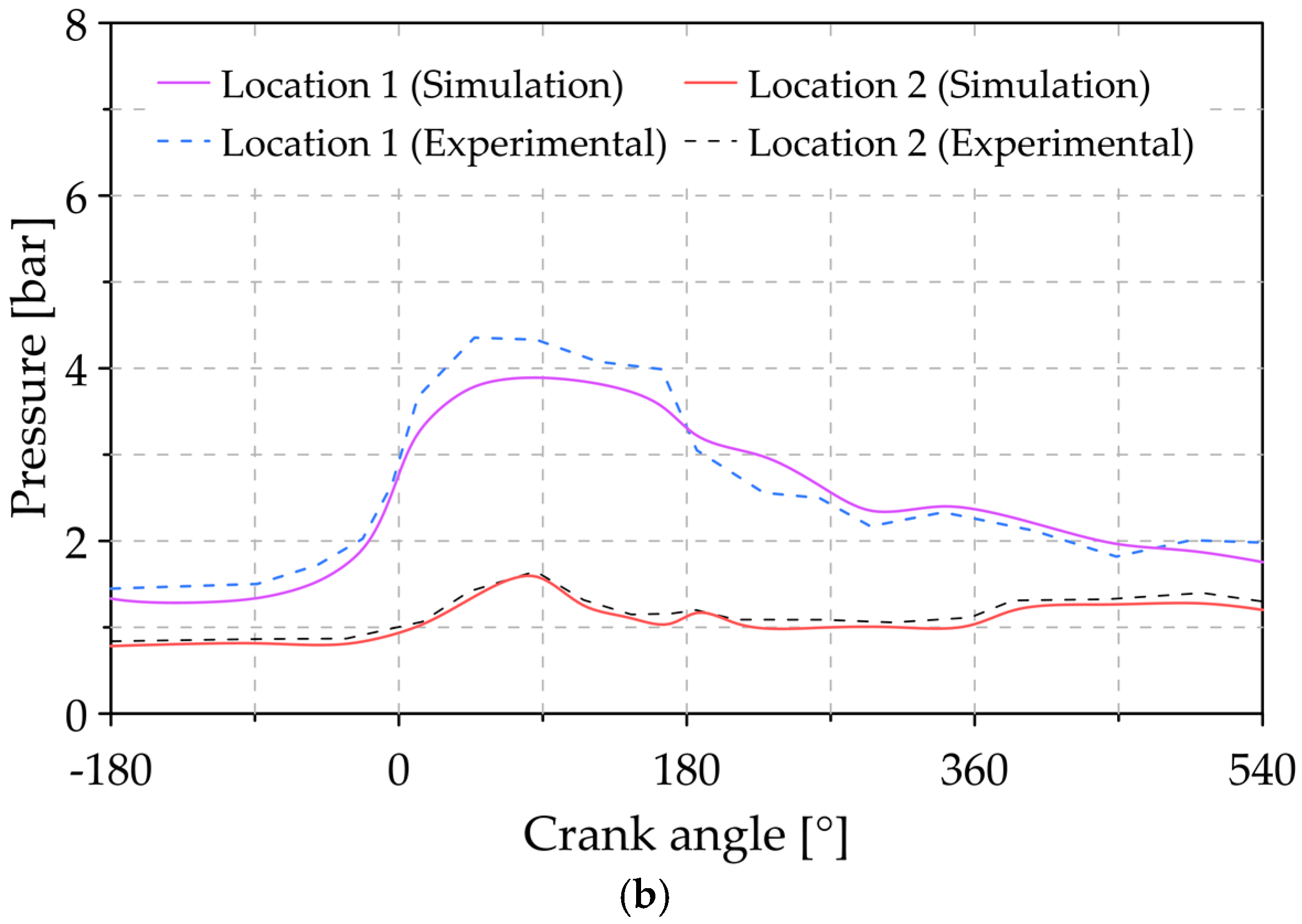
2.3. Experimental Validation

The experimental validation of the model is performed by comparing the pressure levels measured using piezoelectric transducers (KISTLER type 7063-A) installed on the piston. As such, the pressure response is measured directly in the combustion chamber and in locations 1 and 2 (see Figure 7). Figure 8 shows a schematic representation of the sensors installed in the piston.
The comparison between the experimental and simulated pressure data is shown in Figure 9.
According to the results of Figure 9, the pressure curves obtained through the numerical simulation follow the same trend as the experimental measurements. In particular, the maximum relative errors between the simulated and experimental data are 7%, 15%, and 11% for the pressure levels in the combustion chamber, location (1) and location (2), respectively. The maximum error reached in the validation methodology is reasonable considering similar experimental investigations [40,41].

3. Results and Discussions

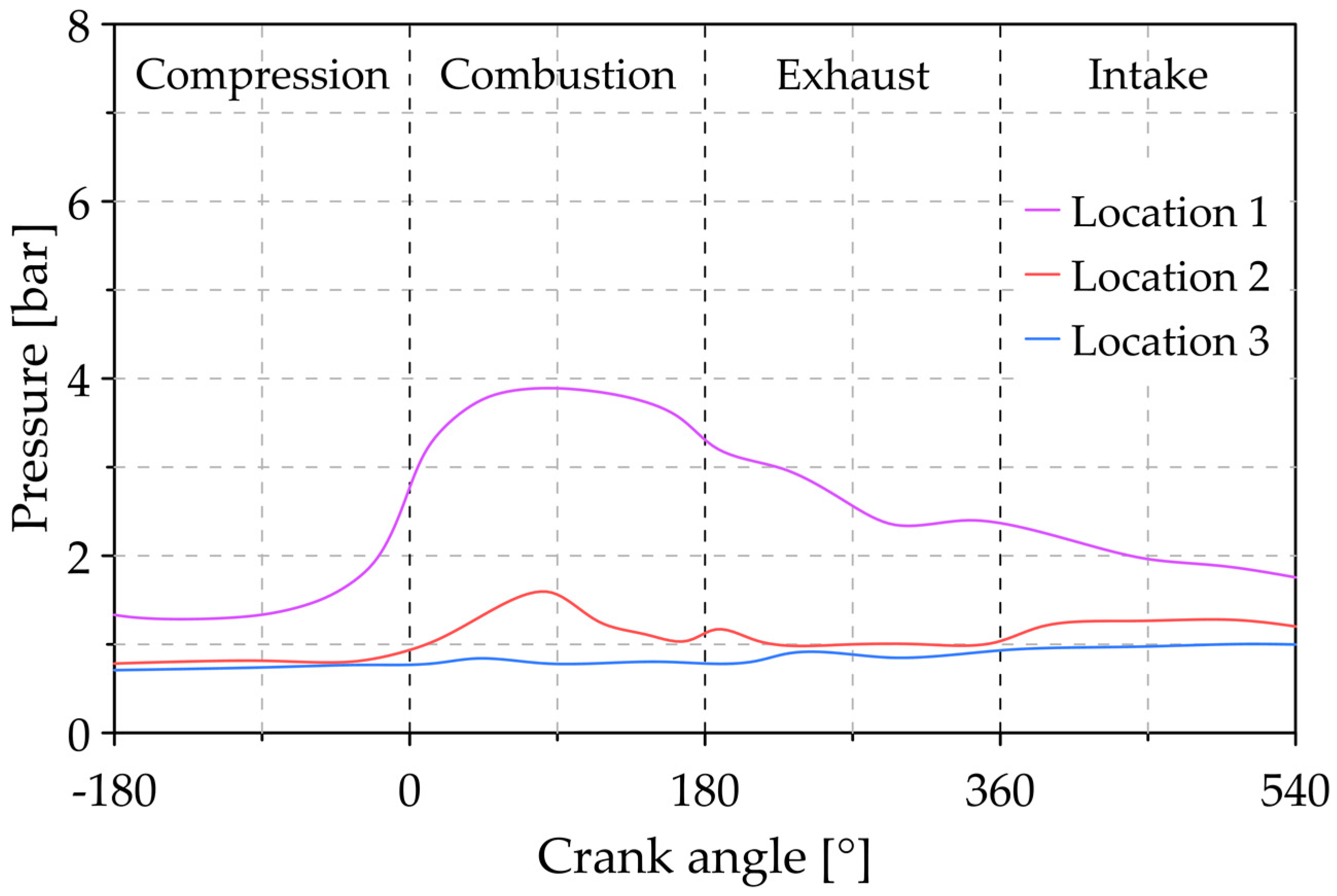
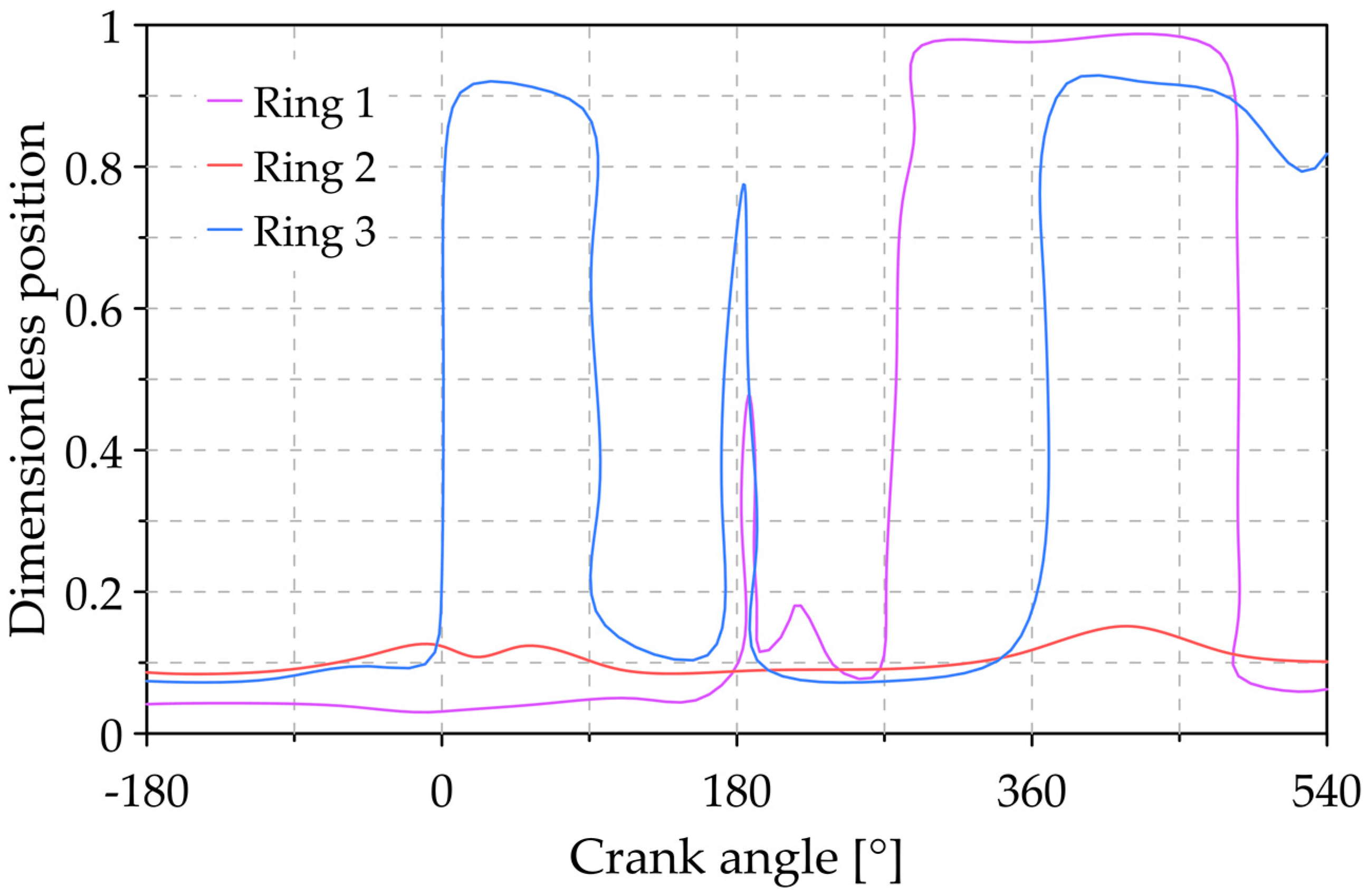
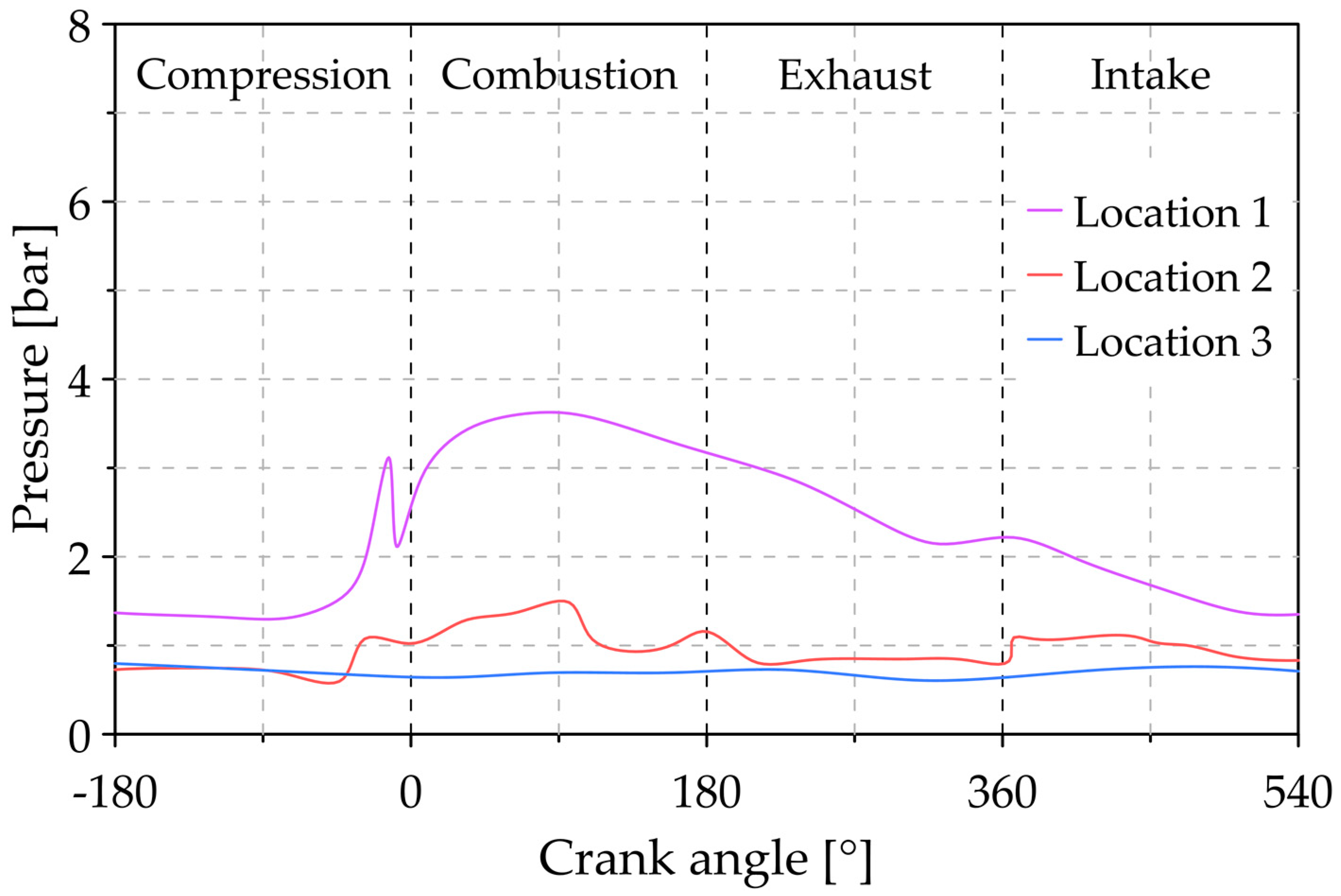
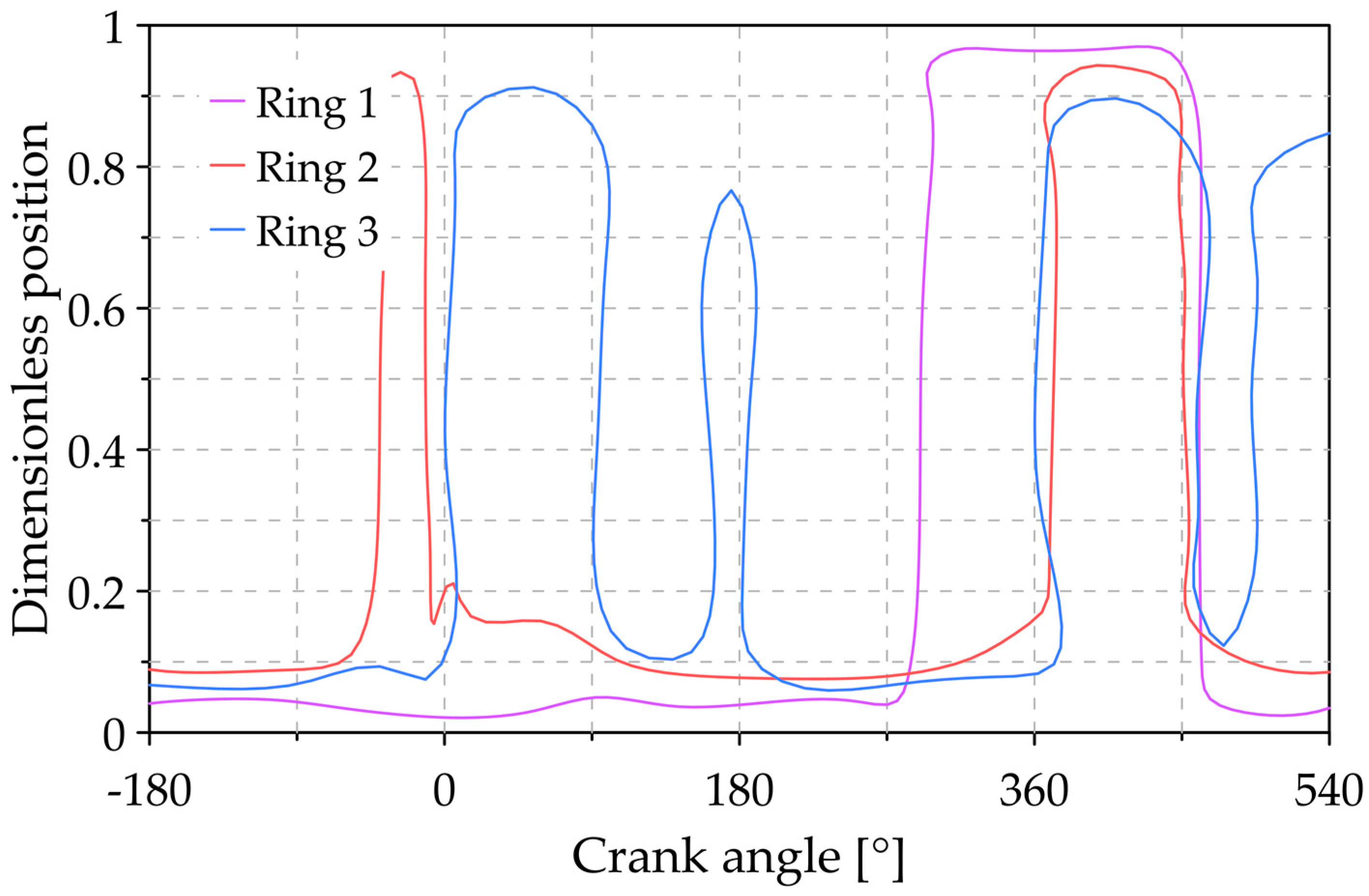
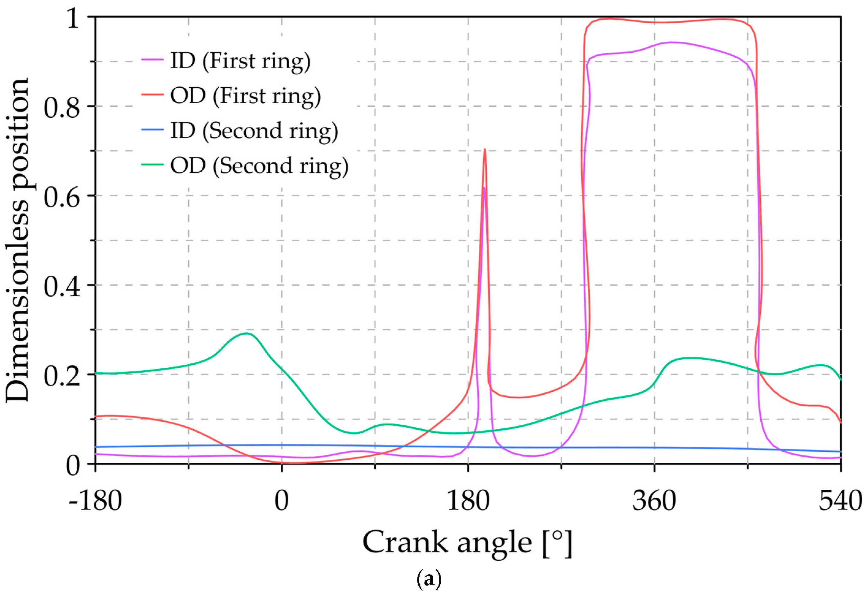
3.1. Analysis of the Reference Conditions

Before conducting the sensitivity analysis proposed in the study (see Table 1), it is crucial to relate the pressure conditions, the position of the rings and the gas flow without such modifications on the compression rings as the baseline.
Firstly, Figure 10 depicts the pressure characteristics at different combustion chamber locations (see Figure 7) under the reference conditions.
Based on the outcomes of Figure 10, during the cycle stages, location (1) features the highest pressure range, and this is significantly higher than the pressure at locations (2) and (3). The latter is a consequence of the direct interaction with the combustion gases at location (1), which raises the pressure in this area. Interestingly, the pressure in location (3) remains constant during the cycle, which can be explained considering that this zone corresponds to the engine crankcase, which is not directly influenced by the combustion phenomena. Overall, the maximum pressure obtained at locations (1) and (2) was 3.89 bar and 1.59 bar, respectively.
Subsequently, Figure 11 displays the relative position of the three piston rings, in which position 0 indicates that the ring is seated at the bottom of the piston groove, and position 1 indicates that the ring is seated in the top. In the case of the first compression ring, it was observed that it remains seated during the compression and combustion stages due to extreme pressure conditions. Additionally, the higher pressure in the backside of the ring during combustion magnifies the contact force, which is the spontaneous mechanism enacted to seal the combustion chamber [33]. However, in the final stage of expansion, an uplift trend occurs in the ring. This trend results from the intensified pressure at location (2), as indicated in Figure 10. Another reason for this can be found considering that the lubricant film in the second groove is mainly influenced by the first ring that, in this case, experiences lower pressures, thus resulting in higher film thickness. As mentioned in Ref. [42], a thicker film degenerates the sealing performance since it contributes to enlarging the ring-bore clearance. The second lift of the first ring occurs between the exhaust and intake stages, which can be attributed to the inertial force of the ring [43]. In contrast, the second compression ring remains at the bottom of the groove during all stages of combustion. Finally, the third piston ring shows a lifting behavior during combustion and air intake. This behavior is attributed to the friction forces of the lubrication oil that surpass the force induced by the pressure at the location (3).
Figure 12 describes the behavior of the gas flows for the different slots (see Figure 6). Positive values indicate a downward flow from the combustion chamber, and negative values indicate that the flows return to the chamber (upward flow).
The largest downward gas flows occur in the groove (1) during the combustion stage. This behavior is a direct consequence of the high pressures in this combustion chamber region [44]. The highest flow peaks occur at the end of the compression, combustion, and intake stages, with a flow of 0.164, 0.085 and 0.065 × 10 3 g/s, respectively. In a general sense, the baseline case analysis serves as the initial point to compare the influence of the design parameters of the compression rings on the sealing capacity of the combustion chamber. The results of the blow-by gas in the reference scenario elucidate the importance of improving the design parameters to minimize pollutant emissions and reduce fuel consumption.

3.2. Analysis of the Influence of Ring Gap

Figure 13 shows the pressure developed in the combustion chamber at different locations when accounting for compression ring gap modifications (see Table 1).
For modification 1 (Figure 13a), the pressure curve follows a similar behavior as in the reference conditions (see Figure 10). However, the pressure levels at location (1) are lower compared to the reference conditions. Specifically, a reduction of 11.12% in the maximum pressure is observed. This result is attributed to the enhanced sealing capacity as the first ring gap is reduced by 25%. An opposite trend occurs at location (2) since the maximum pressure is amplified by around 10.5%, which can be explained considering that increasing the second ring gap promotes a greater flow of gas in this area. Location (3) features the least sensitivity to pressure changes since the compression ring is not being modified.
In modification 2 (Figure 13b), a considerable rise in pressure is shown during the combustion stage, reaching a maximum pressure of 6.63 bar. The latter is a direct consequence of increasing the first ring gap, which fosters a greater concentration of flow in location (1). The effect of ring flutter can be mentioned as another contributor to pressure intensification. In general, it was observed that this modification causes increases in the maximum pressure of 70.5% and 38.2% in locations (1) and (2), respectively.
On the other hand, a combined reduction in the gap of the first and second rings (modification 3) significantly drops the pressure in locations (1) and (2) compared to the reference condition. Specifically, the pressure remains below 2 bar in these zones for all the stages during the combustion cycle. This pattern implies a reduction in the concentration of combustion flow in these areas due to reducing the gap of the compression rings. The pressure gradients along the combustion cycle represent a vital parameter to relate the overall behavior of the compression rings and further assist in explaining the dynamic characteristics involved during each combustion phase. Generally, the interaction between the pressure distributions on each piston and the inertial forces determine the final behavior of the blow-by gas phenomena and the oil consumption of the engine.
Accordingly, Figure 14 shows the relative position of the piston rings for different modifications in the compression ring gap.
According to the results of Figure 14a (modification 1), the elevation of the first ring tends to decrease compared to the reference condition (see Figure 11). This result might be a consequence of the lower pressure levels at the location (1) during the combustion stage due to reducing the first compression ring gap. The variation in the dynamic balance of both the tension force and body contact force can be mentioned as another contributor to this pattern in the radial movement of the ring [33,42]. In the second and third rings, a similar trend is obtained when compared to the reference conditions, except for the final stage of admission in the third ring, which settles in the lower part of the groove.
For modification 2 (Figure 14b), the first ring remains in the upper part of the groove during almost all of the combustion cycle. This pattern can be associated with the intensified pressure in location (1), as shown in Figure 13b. In contrast, the other piston rings did not significantly change their relative position compared to the reference condition.
By reducing the gap in both the first and second rings (modification 3), the first ring tends to stay at the groove bottom, except for in the initial intake stage. This occurs since the pressure at location (1) is lower than the pressure developed in the combustion chamber during much of the combustion cycle. However, the second ring experiences an unstable position during the combustion stages. This behavior could be associated with a similar share between the inertial force and the pressure force that triggers instability in the ring position. For the third ring, it can be inferred that its movement depends to a great extent on the inertial force since the pressures at locations (2) and (3) are not significant (see Figure 13c).
On the other hand, Figure 15 illustrates the flows of combustion gases that escape through the different grooves of the piston rings and the influence of gap modifications in the compression rings.
Figure 15 demonstrates that the variation in the compression ring gap has a significant impact on the gas flow that passes through the piston grooves. Notably, groove (1) presents the critical condition of the blow-by phenomena due to its direct interaction with the combustion chamber. Overall, by reducing the first ring gap (modification 1 and modification 3), the flow of combustion gases through the grooves can be minimized by between 4% and 13% in groove (1). Contrarily, increasing the first ring gap (modification 2) magnifies the gas leakage in the groove (1) by 5.12% compared to the reference conditions. In general, shortening the compression rings’ gap limits the gas leakage, which is a direct indication of improved sealing capacity. However, the excessive reduction produces instabilities in the second piston ring, which can be associated with ring collapse, as corroborated by the pressure behavior in Figure 14c. This collapse condition in the second ring was also observed in other investigations [45,46]. The latter represents the parasitic effect of the sealing capacity that takes place when the pressure in location (2) escalates in a slow manner, allowing the inertial force to keep the compression ring up for an extended period during the combustion cycle thereby boosting the blow-by gas.

3.3. Analysis of the Variation of the Mass of Compression Rings

Figure 16 displays the same sensitivity analysis for the pressure conditions discussed in the previous section when the mass of the compression rings is altered (modification 4).
According to Figure 16, the pressures at locations (1) and (2) are reduced compared to the reference condition. This implies that increasing the mass of the first and second rings improves the sealing capacity of the piston. This behavior can be attributed to higher tension forces since the ring is heavier, which promotes the stiffness of the ring. For the simulated conditions, the maximum pressure decreases by 7% and 7.38% in locations (1) and (2), respectively. In other studies, the effect of mass and inertial force was also outlined to explain the ring flutter phenomena since both parameters influence torsional stiffness, which is commonly controlled by varying the axial height of the ring [33,46]. The flutter occurrence is a non-desirable condition that is attributed to a strong resemblance between the inertial and gas pressure forces [46]. The latter takes relevance since it induces a pronounced clearance between the ring and the groove, thus fostering gas flows and imminent pressure fluctuations, which directly impacts the overall emissions and lubricant oil consumption.
Figure 17 depicts the effect of increasing the mass of the compression rings on the relative position of the piston grooves. The results show that the first ring exhibits a more stable behavior than the reference conditions since it only shows a rise inside the groove during the final exhaust stage and the start of the intake stroke. This stability is mainly attributed to the high combustion pressure that inhibits the ring from lifting. However, in the second ring, a greater variation in its position was observed compared to the reference condition. Specifically, within the combustion cycle, the groove settled at the top during the compression and intake stroke. This behavior is attributed to the augmented inertial and tension forces due to the greater mass in the ring that offsets the pressure force. An experimental study [18] also outlined that the axial ring’s collapse in the second ring is responsible for the unstable behavior in the relative position. This pattern implies that the radial force exceeds both the ring tension and the pressing forces, producing a direct recirculation of gas flow from position (2) to the position (3) of the piston lands, which negatively affects the sealing capacity [45].

3.4. Analysis of the Variation of the Twist Angle of Compression Rings

Figure 18 depicts the changes in the inner and outer diameter for the first and second compression rings by modifying the twist angle.
Unlike previous behaviors, the external and internal diameters of the compression rings are not located in the same position within the groove. For a positive twist angle (Figure 18a), it can be noted that both the outer and inner diameters of the first ring feature a similar trend while remaining at the top position between the combustion and exhaust stages. This condition can be explained considering that the pressure enlargement provokes the inner diameter to lift from the flank of the groove; as such, the trapped gases inside this cavity penetrate a larger area of the bottom side of the ring. Thus, the inertial forces surpass the gas pressure forces, resulting in the upward motion of the entire ring. In this scenario, the whole body of the first ring may lift easily due to the flow pressure at location (1). This pattern is in agreement with an experimental report that outlined that large twist angles reduce the ring resistance as a result of viscous friction effects, which foster the upward trend in the groove [47]. In the second compression ring, a more unstable behavior is obtained since the internal diameter remains in the lower part of the groove during the entire combustion cycle. In contrast, the outside diameter rises steadily, reaching approximately 30% of the groove’s height in the compression stage. This behavior can be explained considering that the twist angle significantly impacts the running face contour and even the lubrication gap between the compression ring and the liner, which directly influences the dynamic characteristics and pressure force of the rings [9,33].
On the other hand, for a negative twist angle (Figure 18b), the first compression ring’s results indicate a greater difference between the relative positions of the inner and outer diameters. This behavior can be explained considering that a negative twist angle enables a larger portion of combustion gases to enter the ring groove, pushing the ring’s inner diameter (see Figure 18b). Similarly, in the second ring, there is a considerable difference between the inner and outer diameter positions. Therefore, we can verify the adverse effects of negative twist angles in the compression rings since they reduce the sealing capacity while promoting a greater quantity of combustion gases to flow through the piston. It is worth mentioning the relevance of examining the twist angle that arises, considering that it can significantly relate to the wear performance of the compression ring. For instance, increasing the twist angle can produce severe wear in the groove lands and ring flanks [33]. Moreover, the real surface patterns of the compression rings possess shape deviations (e.g., waviness, straightness) that are derived from thermal deformation or excessive wear, which determines the appropriate prediction of the overall sealing performance. It can be outlined from this section that the overall behavior of the compression rings does not depend exclusively on the interaction between the pressure gradients and inertial forces, since the location where this interaction takes place features a predominant role in the sealing capacity, as corroborated by the incidence of both the positive and negative twist angles.

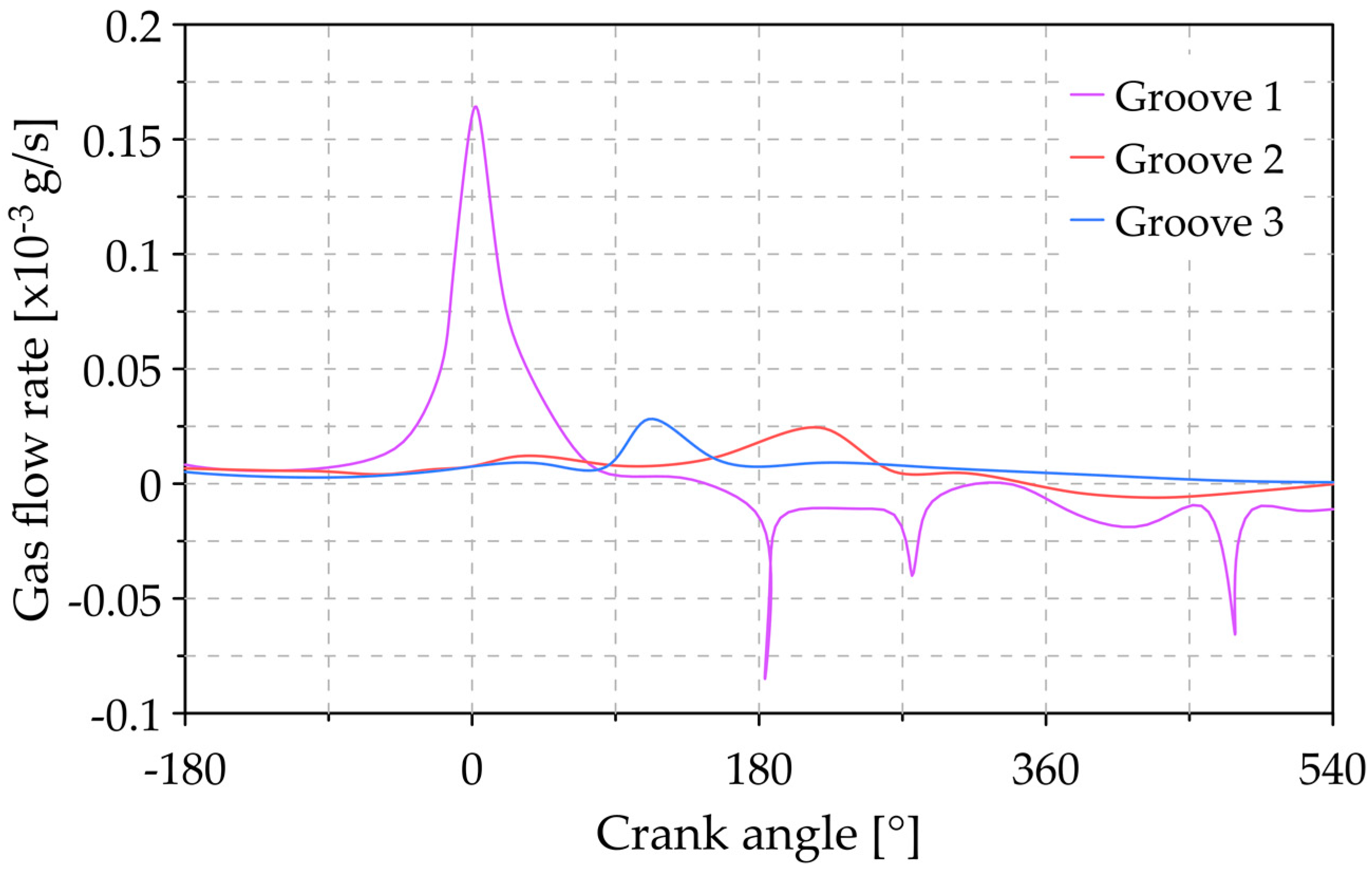
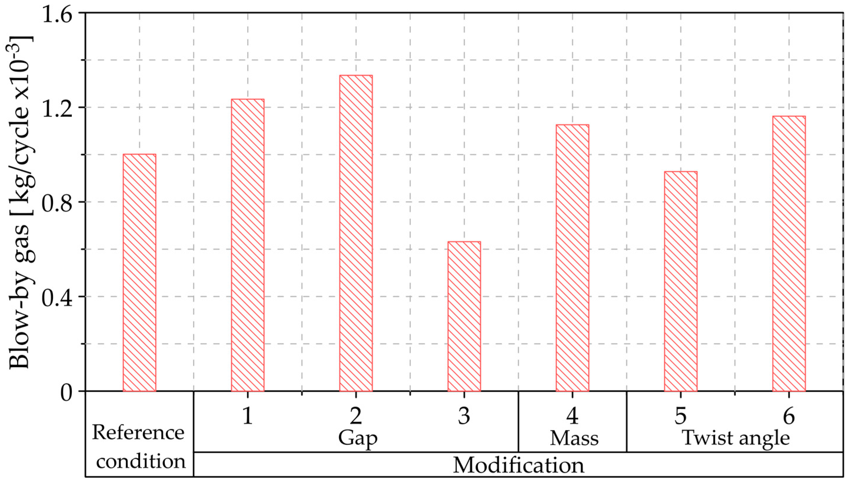
3.5. Analysis of the Variation of Blow-By Gas

This section aims to determine the influence of the modifications above on the blow-by gas phenomena during the combustion cycle, as shown in Figure 19. In this sense, we can compare in broader terms the impact of the design parameters of the compression rings on the sealing capacity.
The results show that only a combined reduction in the ring gap parameter has a positive effect on blow-by gas minimization, as it reduces up to 37% of the combustion gases that end up in the engine crankcase.
On the other hand, increasing the mass of the compression rings boosts the combustion gases leakage, which is a consequence of intensified motion in the second compression ring during the combustion cycle, as shown in Figure 17. It is worth mentioning that the greater mass in the rings benefits the tension forces, which reduces the pressure ranges. However, this positive effect is neutralized by the intensification of the inertia in the rings that magnify the blow-by gas effect. For positive twist angles (modification 5), a substantial reduction in gas leakage to the crankcase was achieved. However, a negative twist angle in the compression rings increases the gas losses by 16.08%. The latter is a consequence of the geometrical disposition that is averse to sealing the groove clearance. It is worth mentioning that unlike blow-by gas phenomena that directly impact global emissions, the reverse blow-by effect considerably increases the lubricating oil consumption [46]. The latter occurs when the pressure of the combustion chamber does not exceed that of the second piston land. Therefore, we can verify the relevance of characterizing this phenomenon to accurately predict and improve the overall performance of the ICEs from a global perspective.

4. Conclusions

The present investigation analyzed the influence of compression rings’ design parameters on the sealing capacity. Accordingly, a sensitivity analysis was introduced to unravel the impact of the gap, mass, and twist angle of the compression rings. A mathematical model is proposed to predict the blow-by phenomena in a single-cylinder diesel engine while accounting for dynamic characteristics. Incorporating the secondary compression ring within the performance evaluation stands as a unique factor of the present investigation.
The results showed the significance of the pressure produced by the combustion gases and the relative motion of the compression rings on the combustion chamber sealing capacity. Specifically, the greatest gas leakage into the crankcase occurs during the compression and combustion stages due to extreme pressure conditions. Under the reference conditions, the gas leakage reaches 0.001 g for each combustion cycle, representing a loss of approximately 0.5% of the gases enclosed in the combustion chamber per cycle.
The sensitivity analysis of the compression ring gap demonstrated that the first piston ring regulates the flow of gases that passes through the grooves of the lower rings, which is reflected in the reduced pressures in these areas. However, the leakage into the crankcase is mainly governed by the relative motion of the secondary piston ring. In general, a combined reduction in the gap of both compression rings minimizes the leakage flows by 37%.
On the other hand, increasing the mass of the compression rings magnifies the gas leakage, which is a direct consequence of the higher inertial forces in the rings. This effect promotes the movement of the rings in their groove, facilitating the free flow of combustion gases.
The positive twist angle of the compression rings fostered a reduction of up to 7.33 × 10 5   g / cycle   in the combustion gases that flow to the crankcase. Contrarily, a negative twist angle caused an increase of 1.61 × 10 4   g / cycle , demonstrating the negative impact of this modification in terms of the sealing capacity. In conclusion, the proposed mathematical model proved reliable in the prediction of the overall behavior related to the sealing capacity of compression rings, which set the basis for more complex analysis. The neglection of the secondary movement of the piston is a significant limitation of the proposed model, which might unravel hidden effects to further optimize the sealing capacity. In future studies, the incorporation of CFD simulations for the compression rings appears to be an interesting avenue. In addition, there is a pressing need to extend the evaluation to other aspects of the engine, such as the effects of lubrication oil consumption and emissions levels, among others.

Author Contributions

Conceptualization, B.H.-C., D.M.-C., and C.P.-G.; methodology, B.H.-C., and D.M.-C.; software, B.H.-C., D.M.-C. and C.P.-G.; validation, B.H.-C.; formal analysis, B.H.-C., and D.M.-C.; investigation, B.H.-C., and D.M.-C.; resources, C.P.-G., M.D.S.F.-V., and J.P.-L.; writing—original draft preparation, B.H.-C., and D.M.-C.; writing—review and editing, C.P.-G., M.D.S.F.-V., and J.P.-L.; funding acquisition, M.D.S.F.-V., and J.P.-L. All authors have read and agreed to the published version of the manuscript.

Funding

This research received no external funding.

Acknowledgments

The authors would like to acknowledge the Universidad del Atlántico, Universidad Francisco de Paula Santander, and Sphere Energy company for their support in the development of this investigation.

Conflicts of Interest

The authors declare no conflict of interest.

Abbreviations

The following abbreviations are used in this manuscript:
Nomenclature
ICE Internal combustion engine
FEAFinite element analysis
T Temperature
P Pressure
c p Model constant
a Acceleration
L Longitude
F Force
m r Piston mass
P h Hydrodynamic pressure
τ Viscous shear stress
A Area
ϕ x ,   ϕ y Pressure flow factors
ϕ s Shear flow factor
h Thickness of the lubrication film
Z Piezo-viscosity index
S o Thermo-viscosity index
ζ Coefficient of asperity shear strength
P a Asperity contact pressure
σ s Surface roughness
β a Average asperity radius of curvature
ξ Asperity distribution
λ The stribeck’s lubricant film ratio
E Equivalent Young’s modulus of elasticity
F 5 / 2 Statistical function of lubricant film ratio
E Modulus of elasticity
ϑ Poisson’s ratio
e t Eccentricities of piston at the top of the skirt
e b Eccentricities of piston at the bottom of the skirt
c c p Clearance between the cylinder liner and piston skirt
L p s Longitude of piston skirt
δ Piston skirt deformation
τ o Limiting Eyring shear stress
A e Effective asperity contact area
F 2 Statistical function of the Stribeck’s lubricant film ratio
P k Specific pressure of the piston ring on the cylinder wall
D Diameter of the ring
b Width of the ring
σ b Bending stress
ϕ s r Shear factor due to local roughness
f Ring gap
L r p Length of the ring
T t Stiffness torsion
D i Inner diameter
D o Outer diameter
m ˙ Mass flow
ϕ s s Shear factor due to sliding velocity
R Gas constant
n g Dynamic viscosity of the gas
S n Sutherland’s number
a g Ring gap area
c d Discharge coefficient
f m Compressibility factor
γ s Ratio of the specific heats
I r Second moment of inertia of the area
A r Cross-sectional area
R r Radius of curvature of the ring
φ Angular position of the ring
C i j Elastic compliance matrix
u Radial direction
w Axial direction
ϕ s p Shear factor due to mean pressure
δ Distance between the wrist pin and axis of the piston
Greek Letters
ρ Density
β Coefficient of thermal expansion
η Viscosity
η Model constant
α o Atmospheric piezo-viscosity coefficient
β o Thermo-viscosity coefficient
α Displacement angle of the connecting rod
ω Angular velocity
θ Displacement angle of the crankshaft
ψ Ring twist angle
Subscripts
o Environmental conditions
a t m Atmospheric
p Piston
r Connecting rod
cCrankshaft
g Combustion gases

References

  1. Amador, G.; Duarte, J.F.; Rincon, A.; Fontalvo, A.; Bula, A.; Padilla, R.V.; Orozco, W. Characteristics of Auto-Ignition in Internal Combustion Engines Operated with Gaseous Fuels of Variable Methane Number. J. Energy Resour. Technol. Trans. ASME 2017, 139. [Google Scholar] [CrossRef]
  2. Ochoa, G.V.; Isaza-Roldan, C.; Duarte Forero, J. Economic and Exergo-Advance Analysis of a Waste Heat Recovery System Based on Regenerative Organic Rankine Cycle under Organic Fluids with Low Global Warming Potential. Energies 2020, 13, 1317. [Google Scholar] [CrossRef] [Green Version]
  3. Pavlovic, J.; Ciuffo, B.; Fontaras, G.; Valverde, V.; Marotta, A. How much difference in type-approval CO2 emissions from passenger cars in Europe can be expected from changing to the new test procedure (NEDC vs. WLTP)? Transp. Res. Part A Policy Pract. 2018, 111, 136–147. [Google Scholar] [CrossRef]
  4. Orozco, W.; Acuña, N.; Duarte, J. Characterization of Emissions in Low Displacement Diesel Engines Using Biodiesel and Energy Recovery System. Int. Rev. Mech. Eng. 2019, 13, 420–426. [Google Scholar] [CrossRef]
  5. Duarte, J.; Garcia, J.; Jiménez, J.; Sanjuan, M.E.; Bula, A.; González, J. Auto-Ignition Control in Spark-Ignition Engines Using Internal Model Control Structure. J. Energy Resour. Technol. Trans. ASME 2017, 139. [Google Scholar] [CrossRef]
  6. Allen, C.M.; Gosala, D.B.; Shaver, G.M.; McCarthy, J. Comparative study of diesel engine cylinder deactivation transition strategies. Int. J. Engine Res. 2019, 20, 570–580. [Google Scholar] [CrossRef]
  7. Oglieve, C.J.; Mohammadpour, M.; Rahnejat, H. Optimisation of the vehicle transmission and the gear-shifting strategy for the minimum fuel consumption and the minimum nitrogen oxide emissions. Proc. Inst. Mech. Eng. Part D J. Automob. Eng. 2017, 231, 883–899. [Google Scholar] [CrossRef] [Green Version]
  8. Duarte, J.; Amador, G.; Garcia, J.; Fontalvo, A.; Vasquez Padilla, R.; Sanjuan, M.; Gonzalez Quiroga, A. Auto-ignition control in turbocharged internal combustion engines operating with gaseous fuels. Energy 2014, 71, 137–147. [Google Scholar] [CrossRef]
  9. Turnbull, R.; Mohammadpour, M.; Rahmani, R.; Rahnejat, H.; Offner, G. Coupled elastodynamics of piston compression ring subject to sweep excitation. Proc. Inst. Mech. Eng. Part K J. Multi-Body Dyn. 2017, 231, 469–479. [Google Scholar] [CrossRef] [Green Version]
  10. Morris, N.; Mohammadpour, M.; Rahmani, R.; Rahnejat, H. Optimisation of the piston compression ring for improved energy efficiency of high performance race engines. Proc. Inst. Mech. Eng. Part D J. Automob. Eng. 2017, 231, 1806–1817. [Google Scholar] [CrossRef] [Green Version]
  11. Baker, C.; Theodossiades, S.; Rahmani, R.; Rahnejat, H.; Fitzsimons, B. On the Transient Three-Dimensional Tribodynamics of Internal Combustion Engine Top Compression Ring. J. Eng. Gas Turbines Power 2017, 139. [Google Scholar] [CrossRef]
  12. Hallouin, B.; Lasseux, D.; Senger, G. Gas flow through a bore-piston ring contact. Int. J. Engine Res. 2020. [Google Scholar] [CrossRef]
  13. Namazian, M.; Heywood, J.B. Flow in the Piston-Cylinder-Ring Crevices of a Spark-Ignition Engine: Effect on Hydrocarbon Emissions, Efficiency and Power; SAE Technical Papers; Society of Automotive Engineers: Warrendale, PA, USA, 1982. [Google Scholar]
  14. Furuhama, S.; Tada, T. On the Flow of Gas through the Piston-Rings: 2nd Report, the Character of Gas Leakage. Bull. JSME 1961, 4, 691–698. [Google Scholar] [CrossRef]
  15. Tomanik, E.; Sobrinho, R.M.S.; Zecchinelli, R. Influence Of Top Ring End Gap Types At Blow-By Of Internal Combustion Engines. SAE Tech. Pap. 1993. [Google Scholar] [CrossRef]
  16. Wannatong, K.; Chanchaona, S.; Sanitjai, S. Simulation algorithm for piston ring dynamics. Simul. Model. Pract. Theory 2008, 16, 127–146. [Google Scholar] [CrossRef]
  17. Keribar, R.; Dursunkaya, Z.; Flemming, M.F. An Integrated Model of Ring Pack Performance. J. Eng. Gas Turbines Power 1991, 113, 382–389. [Google Scholar] [CrossRef]
  18. Przesmitzki, S.; Tian, T. An Experimental Study of the Time Scales and Controlling Factors Affecting Drastic Blow-by Increases during Transient Load Changes in SI Engines. SAE Tech. Pap. 2008. [Google Scholar] [CrossRef]
  19. Iijima, N.; Miyamoto, T.; Takiguchi, M.; Kai, R.; Sato, M. An Experimental Study on Phenomena of Piston Ring Collapse. SAE Tech. Pap. 2002. [Google Scholar] [CrossRef]
  20. Tian, T. Dynamic behaviours of piston rings and their practical impact. Part 2: Oil transport, friction and wear of ring/liner interface and the effects of piston and ring dynamics. Proc. Inst. Mech. Eng. Part J J. Eng. Tribol. 2002, 216, 229–248. [Google Scholar] [CrossRef]
  21. Dowson, D.; Higginson, G.R. A Numerical Solution to the Elasto-Hydrodynamic Problem. J. Mech. Eng. Sci. 1959, 1, 6–15. [Google Scholar] [CrossRef]
  22. Yang, P.; Cui, J.; Jin, Z.M.; Dowson, D. Transient elastohydrodynamic analysis of elliptical contacts. Part 2: Thermal and Newtonian lubricant solution. Proc. Inst. Mech. Eng. Part J J. Eng. Tribol. 2005, 219, 187–200. [Google Scholar] [CrossRef]
  23. Roelands, C.J.A.; Winer, W.O.; Wright, W.A. Correlational Aspects of the Viscosity-Temperature-Pressure Relationship of Lubricating Oils (Dr In dissertation at Technical University of Delft, 1966). J. Lubr. Technol. 1971, 93, 209–210. [Google Scholar] [CrossRef] [Green Version]
  24. Houpert, L. New Results of Traction Force Calculations in Elastohydrodynamic Contacts. J. Tribol. 1985, 107, 241–245. [Google Scholar] [CrossRef]
  25. Perera, M.S.M.; Theodossiades, S.; Rahnejat, H. Elasto-multi-body dynamics of internal combustion engines with tribological conjunctions. Proc. Inst. Mech. Eng. Part K J. Multi-Body Dyn. 2010, 224, 261–277. [Google Scholar] [CrossRef] [Green Version]
  26. Consuegra, F.; Bula, A.; Guillín, W.; Sánchez, J.; Duarte Forero, J. Instantaneous in-Cylinder Volume Considering Deformation and Clearance due to Lubricating Film in Reciprocating Internal Combustion Engines. Energies 2019, 12, 1437. [Google Scholar] [CrossRef] [Green Version]
  27. Patir, N.; Cheng, H.S. Application of Average Flow Model to Lubrication between Rough Sliding Surfaces. J. Lubr. Technol. 1979, 101, 220–229. [Google Scholar] [CrossRef]
  28. Patir, N.; Cheng, H.S. An Average Flow Model for Determining Effects of Three-Dimensional Roughness on Partial Hydrodynamic Lubrication. J. Lubr. Technol. 1978, 100, 12–17. [Google Scholar] [CrossRef]
  29. Greenwood, J.A.; Tripp, J.H. The Contact of Two Nominally Flat Rough Surfaces. Proc. Inst. Mech. Eng. 1970, 185, 625–633. [Google Scholar] [CrossRef]
  30. Teodorescu, M.; Balakrishnan, S.; Rahnejat, H. Integrated Tribological Analysis within a Multi- physics Approach to System Dynamics. Tribol. Interface Eng. Ser. 2005, 48, 725–737. [Google Scholar]
  31. Makartchouk, A. Diesel Engine Engineering: Thermodynamics, Dynamics, Design, and Control; CRC Press: Boca Raton, FL, USA, 2002; Volume 143. [Google Scholar]
  32. Tian, T.; Noordzij, L.B.; Wong, V.W.; Heywood, J.B. Modeling Piston-Ring Dynamics, Blowby, and Ring-Twist Effects. J. Eng. Gas Turbines Power 1998, 120, 843–854. [Google Scholar] [CrossRef]
  33. Lyubarskyy, P.; Bartel, D. 2D CFD-model of the piston assembly in a diesel engine for the analysis of piston ring dynamics, mass transport and friction. Tribol. Int. 2016, 104, 352–368. [Google Scholar] [CrossRef]
  34. Rahmani, R.; Theodossiades, S.; Rahnejat, H.; Fitzsimons, B. Transient elastohydrodynamic lubrication of rough new or worn piston compression ring conjunction with an out-of-round cylinder bore. Proc. Inst. Mech. Eng. Part J J. Eng. Tribol. 2012, 226, 284–305. [Google Scholar] [CrossRef] [Green Version]
  35. Lang, T.E. Vibration of Thin Circular Rings, Part 1; Jet Propulsion Laboratory: Pasadena, CA, USA, 1962.
  36. Sutherland, L.W. The viscosity of gases and molecular force. Philos. Mag. 1893, 36, 507–531. [Google Scholar] [CrossRef] [Green Version]
  37. Theaker, M.; Rahmani, R.; Rahnejat, H. Prediction of Ring-Bore Conformance and Contact Condition and Experimental Validation. In Proceedings of the ASME 2012 Internal Combustion Engine Division Spring Technical Conference, Piemonte, Italy, 6–9 May 2012; pp. 885–892. [Google Scholar]
  38. Zhu, D.; Hu, Y.-Z.; Cheng, H.S.; Arai, T.; Hamai, K. A Numerical Analysis for Piston Skirts in Mixed Lubrication: Part II—Deformation Considerations. J. Tribol. 1993, 115, 125–133. [Google Scholar] [CrossRef]
  39. Cantore, G.; Giacopini, M.; Rosi, R.; Strozzi, A.; Pelloni, P.; Forte, C.; Achiluzzi, M.; Bianchi, G.M.; Ceschini, L.; Morri, A. Validation of a combined CFD/FEM methodology for the evaluation of thermal load acting on aluminum alloy pistons through hardness measurements in internal combustion engines. Metall. Sci. Tecnol. 2011, 29, 16–25. [Google Scholar]
  40. Richardson, D.E. Comparison of Measured and Theoretical Inter-Ring Gas Pressure on a Diesel Engine; SAE Technical Papers; SAE International: Warrendale, PA, USA, 1996. [Google Scholar]
  41. Dursunkaya, Z.; Keribar, R.; Richardson, D.E. Experimental and Numerical Investigation of Inter-Ring Gas Pressures and Blowby in a Diesel Engine. SAE Tech. Pap. 1993. [Google Scholar] [CrossRef]
  42. Nikolakopoulos, P.G. Simulation of deposits effect on cylinder liner and influence on new and worn compression ring of a turbocharged DI engine. Simul. Model. Pract. Theory 2021, 106, 102195. [Google Scholar] [CrossRef]
  43. Delprete, C.; Selmani, E.; Bisha, A. Gas escape to crankcase: Impact of system parameters on sealing behavior of a piston cylinder ring pack. Int. J. Energy Environ. Eng. 2019, 10, 207–220. [Google Scholar] [CrossRef] [Green Version]
  44. Selmani, E.; Bisha, A. Engine Speed and Load on the Sealing Capacity of a Piston Ring-Pack. Eur. J. Eng. Res. Sci. 2020, 5, 304–313. [Google Scholar] [CrossRef]
  45. Cheng, C.; Schock, H.; Richardson, D. The dynamics of second ring flutter and collapse in modern diesel engines. J. Eng. Gas Turbines Power 2015, 137. [Google Scholar] [CrossRef]
  46. Tian, T. Dynamic behaviours of piston rings and their practical impact. Part 1: Ring flutter and ring collapse and their effects on gas flow and oil transport. Proc. Inst. Mech. Eng. Part J J. Eng. Tribol. 2002, 216, 209–228. [Google Scholar] [CrossRef]
  47. Kurbet, S.N.; Kumar, R.K. A finite element study of piston tilt effects on piston ring dynamics in internal combustion engines. Proc. Inst. Mech. Eng. Part K J. Multi-Body Dyn. 2004, 218, 107–117. [Google Scholar] [CrossRef]
Figure 1. Primary piston movement.
Lubricants 09 00025 g001
Figure 2. Control volumes for the gas blow-by model.
Lubricants 09 00025 g002
Figure 3. Piston skirt compliance matrix.
Lubricants 09 00025 g003
Figure 4. Points for mesh independence analysis.
Lubricants 09 00025 g004
Figure 5. Mesh independence analysis at different locations.
Lubricants 09 00025 g005
Figure 6. (a) Positive twist angle and (b) negative twist angle.
Lubricants 09 00025 g006
Figure 7. Piston ring geometry.
Lubricants 09 00025 g007
Figure 8. Pressure sensor installation diagram.
Lubricants 09 00025 g008
Figure 9. Experimental validation of the simulation results in the (a) combustion chamber and (b) in locations 1 and 2.
Lubricants 09 00025 g009aLubricants 09 00025 g009b
Figure 10. Pressure at different locations in the combustion chamber under reference conditions.
Lubricants 09 00025 g010
Figure 11. Relative positions of piston rings for reference conditions.
Lubricants 09 00025 g011
Figure 12. Gas flow for the different grooves under reference conditions.
Lubricants 09 00025 g012
Figure 13. Pressure in the combustion chamber for (a) modification 1, (b) modification 2 and (c) modification 3.
Lubricants 09 00025 g013aLubricants 09 00025 g013b
Figure 14. Relative position of the piston rings for (a) modification 1, (b) modification 2 and (c) modification 3.
Lubricants 09 00025 g014
Figure 15. Flow of combustion gases in the piston grooves for (a) modification 1, (b) modification 2, and (c) modification 3.
Lubricants 09 00025 g015aLubricants 09 00025 g015b
Figure 16. Pressure in the combustion chamber for modification 4.
Lubricants 09 00025 g016
Figure 17. Relative position of piston rings for modification 4.
Lubricants 09 00025 g017
Figure 18. Relative position of piston rings for modifications 5 and 6, (a) positive twist angle and (b) negative twist angle.
Lubricants 09 00025 g018aLubricants 09 00025 g018b
Figure 19. Blow-by gas for the different modifications.
Lubricants 09 00025 g019
Table 1. Modification of the compression ring parameters.
ModificationParameterFirst RingSecond Ring
1Gap−25% G 1 +25% G 2
2+25% G 1 G 2
3−25% G 1 −25% G 2
4Mass+50% m 1 +50% m 2
5Twist anglePositivePositive
6NegativeNegative
Table 2. Diesel engine.
ModelSK-MDF300
ManufacturerSOKAN
Bore × stroke78 mm × 62.57 mm
Engine type1 cylinder
Maximum power4.6 hp at 3600 rpm
Cycle4 Strokes
Injection systemDirect injection
Displaced volume299 CC
Compression ratio20:1
Intake systemNaturally Aspirated
Publisher’s Note: MDPI stays neutral with regard to jurisdictional claims in published maps and institutional affiliations.

