
An Overview of Thermal Plasma Arc Systems for Treatment of Various Wastes in Recovery of Metals


1
FZU-Institute of Physics of Czech Academy of Science, Prague 8, Na Slovance 1999/2, 18221 Prague, Czech Republic
2
Department of Civil Engineering and Architecture, University of Catania and UdR-Catania Consorzio INSTM, Viale Andrea Doria 6, 95125 Catania, Italy
*
Author to whom correspondence should be addressed.
Materials 2022, 15(2), 683; https://0-doi-org.brum.beds.ac.uk/10.3390/ma15020683
Submission received: 12 October 2021
/
Revised: 31 December 2021
/
Accepted: 14 January 2022
/
Published: 17 January 2022
(This article belongs to the Special Issue Advances in the Use of Green Technologies in Various Areas)
Abstract
:Thermal plasma systems are being used for the recovery of metals from complex waste and minerals. The latter contain multiphase metals in various forms that are extremely tedious to separate. Thermal plasma arc melts the waste and minerals for qualitative plasma products for powder industries. In this overview, we briefly report a description of the various thermal plasma systems and their uses in recovering metal from metal-containing materials in the form of waste or minerals. Various plasma arc systems, such as transferred, nontransferred, and extended arc, have enabled the development of an efficient and environmentally friendly way to recover valuable metals from industrial wastes such as red mud and minerals such as ilmenite.
1. Introduction
Metal-containing materials fall into various categories, from waste materials to minerals. Metals are hidden resources in the waste materials generated from the day-to-day industrial production of human needs [1,2,3], such as metal-containing waste generated from electronic products, metal plants, minerals sectors, and metal-containing soils and minerals [4,5]. To utilize this waste in a valuable way, both hydro- and pyrometallurgical treatments have been proposed in industrial sectors. However, hydrometallurgical treatments create acidic and alkaline residual threats to the environment; as a result, the focus has been shifted more significantly toward pyrometallurgical routes. Thermal plasma is an efficient way to treat metal-containing waste materials. Plasma, generated in a highly ionized state, operates with a high energy density at high temperature. Such a system could enable the degradation of organic compounds from electronic waste materials into elemental ions and atoms, with end-products including gases [6,7,8]. Plasma waste treatment falls into various categories, such as plasma gasification and vitrification of hazardous wastes into slags. The high temperatures of the plasma melt organic and inorganic pollutants into reduced slag. The slag generated by plasma technology is very stable, less harmful, and easy to handle for further treatment. However, volatile metals do not remain in slag during plasma melting of waste material. In plasma reduction, high temperature acts as a boon for soil-containing metals in multiphase forms; for example, waste from the bauxite industry, known as red mud, and ilmenite. The different recovery methods of the valuable metals using various processes by thermal plasma are summarized in Table 1 [9,10,11,12,13,14,15].
Plasma is classified into two broad categories: high and low temperature. The first category comprises a completely ionized system in which the temperature reaches 106–107 °C and above, whilst low-temperature plasma exhibits partially ionized plasma with temperatures falling in the range of 101–105 °C. Low-temperature plasma is divided in two categories, thermal and nonthermal, based on the thermodynamic equilibrium temperature. Thermal plasma combines arc plasma, combustion plasma, and high-frequency plasma in its categories. Thermal plasma has wide application in treatment of wastes from wide areas, such as electronic wastes, steel-making waste, electroplating waste, etc. In the case of nonthermal plasma, generation depends on the dielectric discharge, pulsed alternating current, pulse direct current microwave, gliding arc discharge, etc.
Figure 1 shows the main region in a plasma jet flow. When a plasma arc is released through the nozzle, it creates a laminar layer on the exterior layer of the arc. The inner and outer difference in velocity produces a ring vortex of flow downstream that allows the repeating of the process from the nozzle. Surroundings vortex rings collide with the main stream and form larger vortices that generate wave instability. The distorted vortex rings entangle with adjacent ones, leading to large eddies of turbulent flow. This is the entrainment of the external air, with the whole process contributing to the system’s entropy growth. Argon is considered a plasma gas, as it is able to generate of plasma. Reynolds numbers in the case of argon are lower than air in the creation of plasma [15,16].
2. Different Types of Thermal Plasma Arc Systems
Plasma consists of excited ions of gaseous atoms and free electrons that are able to conduct electricity. The plasma temperature can reach up to 15,000 °C or more. These temperature conditions are sufficient enough to lead to the materials’ melting and vaporization. High-temperature plasma arc can be used for several purposes, such as cutting, coating, machining, welding, heating, etc. Artificially generated plasma can be created by using a plasma-forming gas (argon, nitrogen, or hydrogen) in a gas chamber at a high flow rate (1–5 m3/h), and containing a tungsten electrode as the cathode of a DC power source. The positive electrode can be connected to the workpiece or to the nozzle of the gas chamber. Based on the type of connection, plasma is classified into different arc systems. Plasma is generated by ways such as thermal ionization, gas discharge, photoionization, etc. In the chemical sector, gas discharge is one of the common methods to create plasma. Plasma arc discharge is divided into various forms depending on the applied electric field and gas discharge. There are AC, DC, and RF discharge, as well as microwave discharge types. In the industry and in a semipilot plant, major three types of plasma arc are very functional, such as: (a) nontransferred arc discharge; (b) transferred arc discharge; and (c) extended arc discharge [19,20]. Waste materials in the plasma jet are carried out easily in arc discharge types.
2.1. Nontransferred Arc Discharge Plasma
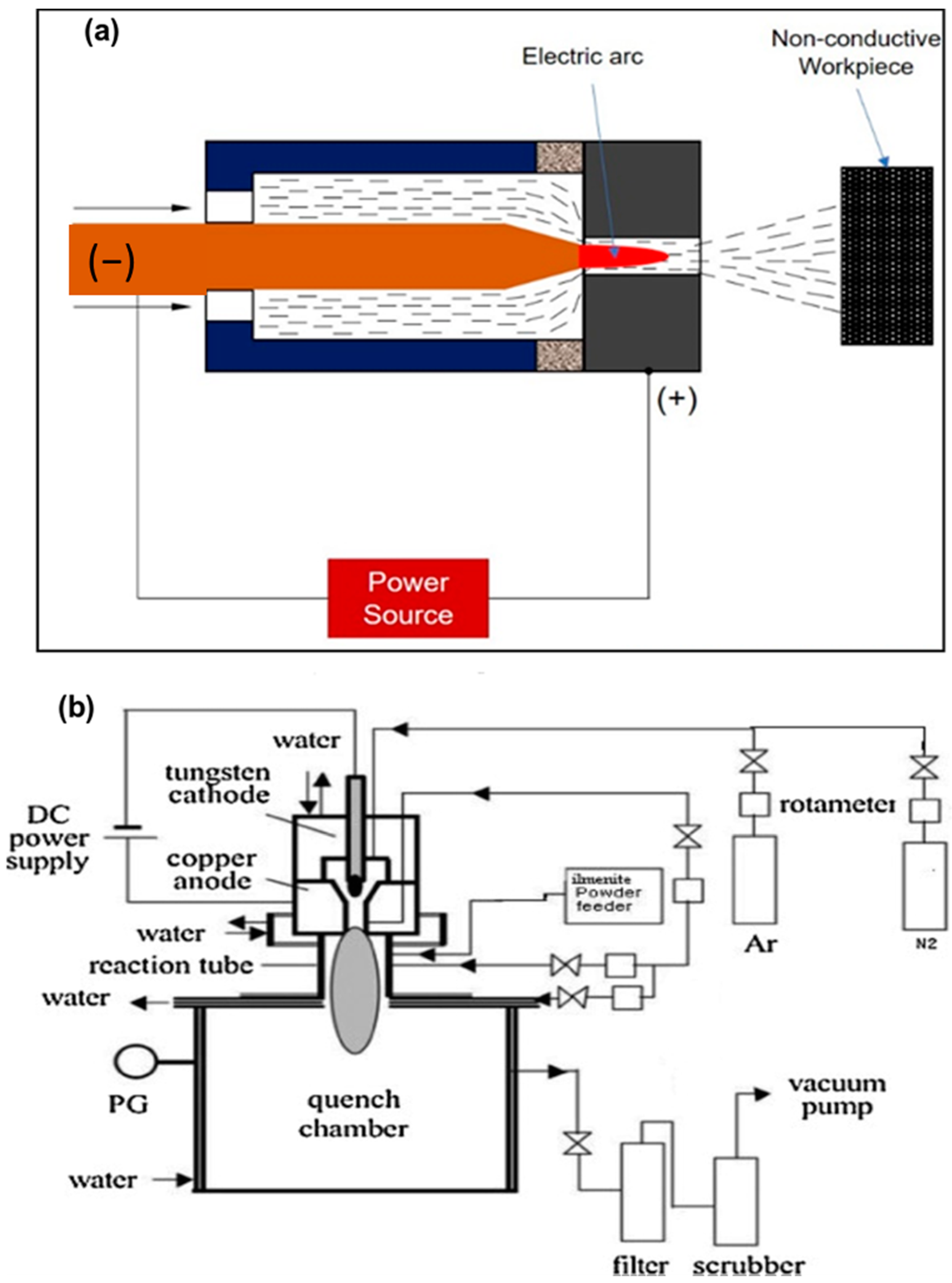
This typology of arc plasma refers to a nondirect plasma arc system The copper nozzle acts as a cathode with the positive terminal of the DC power source, without any connection to the workpiece. The electric arc generates between the electrode itself. The plasma gas generates the arc through the nozzle and releases with a high velocity and temperature. The maximum temperature and velocity that can be reached by a plasma jet are of 11,726 °C and 600 m/s, respectively. Different types of geometry of electrodes are used in the plasma formation in this system, with the cathode constituted by a cylindrical bar and the anode by a hollow cylinder, or at least by two coaxial cylinders. The cooling is maintained by a water-cooling system connected with electrodes. Nontransferred arc torches offer powers ranging from 1 to 6 MW. Figure 3a shows a schematization of a nontransferred arc system, whilst in Figure 3b, a reactor system is shown [21].
2.2. Transferred Arc Plasma System
A workpiece as an integral part of the electrodes that are involved in electric circuits for the formation of plasma represents this typology, in which the workpiece and the electrode are connected, respectively, with the positive and the negative poles of a DC power source. A voltage of 200 V is applied between the cathode and anode with a maximum gap of 5–10 mm, creating an arc. The arc is more accelerated by plasma-forming gas, and is released as a plasma arc through the nozzle and strikes the workpiece. The transferred arc plasma is also called a direct plasma torch. The transferred arc reactor has heating efficiencies higher than 90%, with the limited requirement of gaseous flow for plasma generation. In Figure 4a,b, the arc and plasma reactor are schematized [22,23,24].
2.3. Extended Arc Plasma
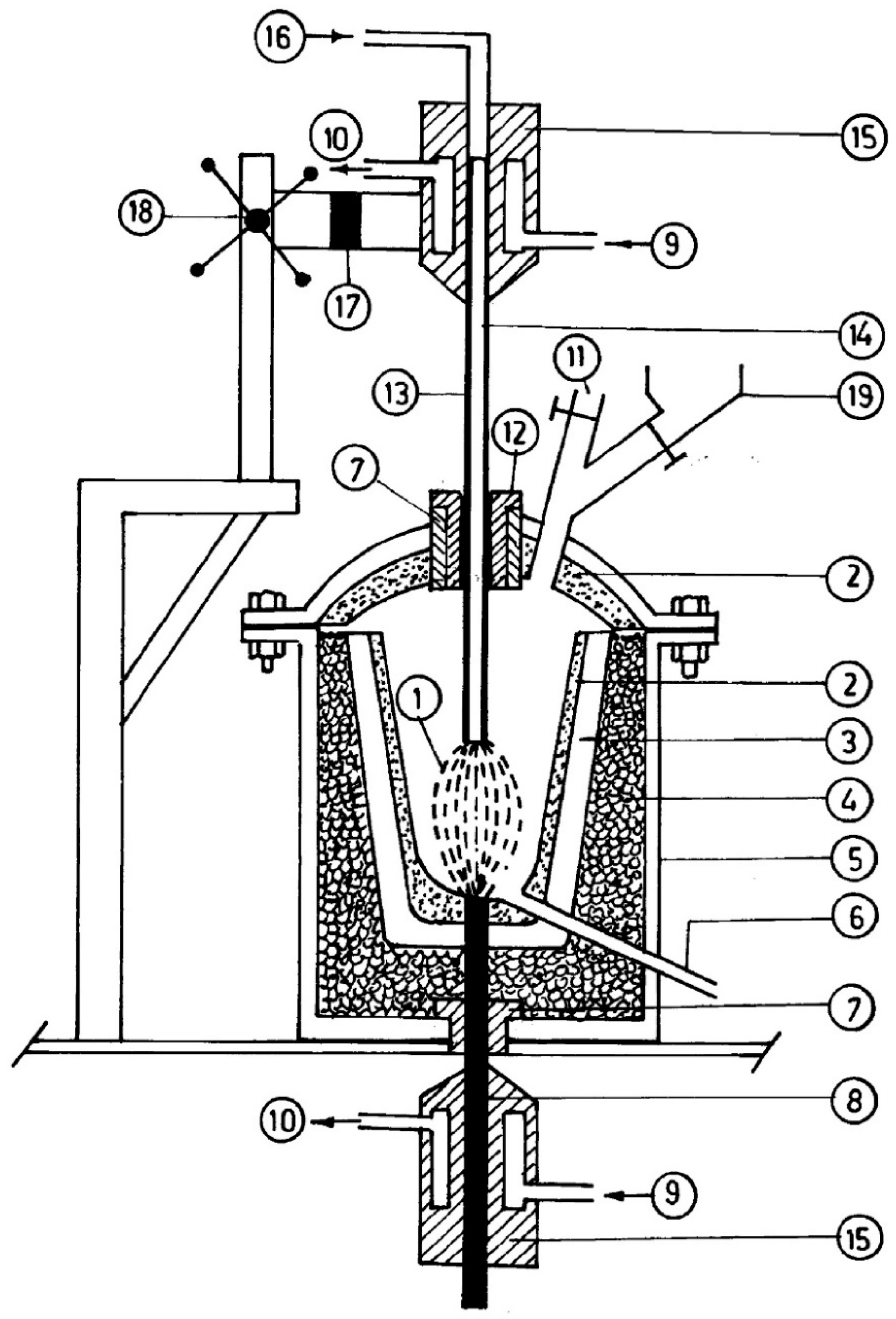
Graphite electrodes, the behavior of which is more stable, allow the formation of a modified or extended arc. Usually, by using an electrode axial hole, it is possible to introduce plasma-forming argon into the arc zone, where the gas ionizes quite readily as soon as the electrodes become hot. By reducing the noise level, a considerable arc length extension is also possible. Figure 5 displays a scheme of an extended plasma reactor [25].
2.4. DC Plasma Reactor with Triple Cathode Arc Device
The triple-torch plasma reactor (TTPR), which is schematized in Figure 6, is extensively employed in the chemical vapor deposition method [26,27].
The three identical torches, operating in the range of 100 to 700 amperes, have been included in the reactor. The operating range of the arc voltage is from 28 to 53 volts when using argon or an argon/hydrogen mixture. The torches are cooled with distilled water, reaching an efficiency that falls between 45–52%, depending on the operating condition. The angle between the torch and the central line varies from 14 to 40°, with a neutral position at 30° w.r.t. the centerline. The torches can move longitudinally around the central axis by about 10 cm. A water-cooling system is supported externally to the reactor. The torch penetrates the chamber through three flexible welded metal below. The dimensions of the reactor are 50 cm in diameter and 64 cm in height, with a double walled water-cooled system. The inner chamber consists of stainless steel to avoid any corrosion. TTPR reactors are extensively used for the synthesis of fine powders such as AlN, Si3N4, and ZrC. A single torch plasma jet reactor is using liquid injection system for various areas of carbides, oxides, composites coatings.
3. Plasma Treatment of Various Types of Wastes
Plasma treatment is divided into various types as follows:
- (a)
- Plasma pyrolysis, which allows the breakdown of chemical compounds.
- (b)
- Plasma gasification, which allows the conversion of organic compounds into a combustible gas that is generally used to generate electric power.
- (c)
- Plasma vitrification of solid wastes, such as the hazardous waste example from alkaline red mud into neutral slag or inorganic material with hazardous metals into the ceramic matrix by adding suitable flux material, with conversion into vitrified ceramics.
- (d)
- In combination with plasma pyrolysis and plasma vitrification or plasma gasification with plasma vitrification for organic solids.
Various categories of hazardous wastes fall under the section of plasma treatment:
- Liquids and gases containing chlorinated fluorocarbons undergo pyrolysis by the plasma process. This chemical process minimizes the formation of hazardous products. Nontransferred plasma torches are mostly used in this process.
- Solid municipal wastes, with low contamination, or hospital wastes, with high contamination, are treated by transferred arc reactors due to the high heat fluxes that allow the melting of solids.
- Incinerators residues such as fly ash, which often contain heavy metals as contaminants. These wastes are generally treated by plasma with the breakdown of metal and slag.
- Low-level radioactive wastes, asbestos, and military wastes have higher negative values and are not possible to dispose of in landfills. Plasma treatment of these wastes results in volume reduction, with the transformation of hazardous waste material into glassy slag.
4. Thermal Plasma Processing
Particulate materials, both solid (particles) and liquid (droplets), fed or injected into a thermal plasma arc are usually treated as the dispersed phase. A stochastic approach has been introduced using heat and mass to consider particle dispersion. A plasma jet allows the complete evaporation of wastes into ionic products, and thermal product material is obtained with subsequent quenching, which prevents undesired reaction processes [30].
4.1. Use of Thermal Plasma in Various Fields
Plasma smelting reduces the wastes and pollutants from complex compounds to simpler forms. The smelting reduction results in smaller molecules and the conversion of organic compounds to inorganic, with melted metal collected to form slag. The particles are strongly bombarded by the energetic electrons and become ionized in an excited state, thus leading to chemical reactions and the conversion from waste to simpler compounds, with residues of metal in the slag [31]. Plasma melting uses a plasma arc as a heat source for the reduction process and subsequent melting. The high temperature of the plasma flame (10,000 °C) allows metal to melt for the following separation and purification. The materials inside the plasma furnace melt and form a high-temperature molten metal pool, which is tapped in a container for cooling down into a solidified stable slag. The system consists of a plasma generator, water-cooling device, high-pressure control system, plasma-forming and carrier-gas control system, power system, and residual collection. A thermal plasma system offers feed capability; an independent energy source; high temperature, flux, and output with rapid response; low electrode consumption; and a low noise level output.
4.2. Thermal Plasma Technology for Waste Reduction
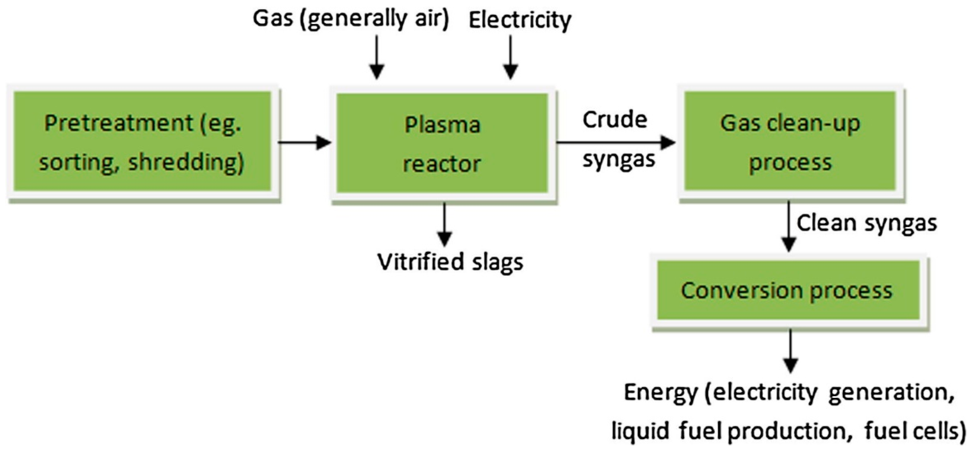
Waste treatment is approved via some of the consideration factors such as safety, community acceptance, and following norms of regulation. Thermal plasma has been developed as one of the efficient technologies in the reduction of various types of waste materials, such as electronics, e-waste, engineering plastic, hazardous waste, municipal solid waste, health care waste, and organic waste materials. High-temperature plasma pyrolysis allows the separation of the slag metal. The reaction kinetics speed up in the presence of plasma ions and radicals, which promote a faster reaction process and time. Plasma processing of printed circuit board waste showed metal recovery of Ag, Au, Cu, Pb, Pd, and Sn of 76%, with a more than 700 kg/day scale basis [32,33]. During the plasma melting of e-waste, a huge amount of carbon monoxide is produced, which can be considered as energy gas. Thermal plasma technology has a high economic and energy value in the sector of waste treatment. A combined process of thermal plasma technology followed by acid leaching enhanced the metal recovery step from e-waste. The extended arc plasma torch system has treated e-waste for the production of valuable metals such as Cu, Al, and Fe [34]. A schematic flow chart for the plasma treatment of solid waste is shown in Figure 7.
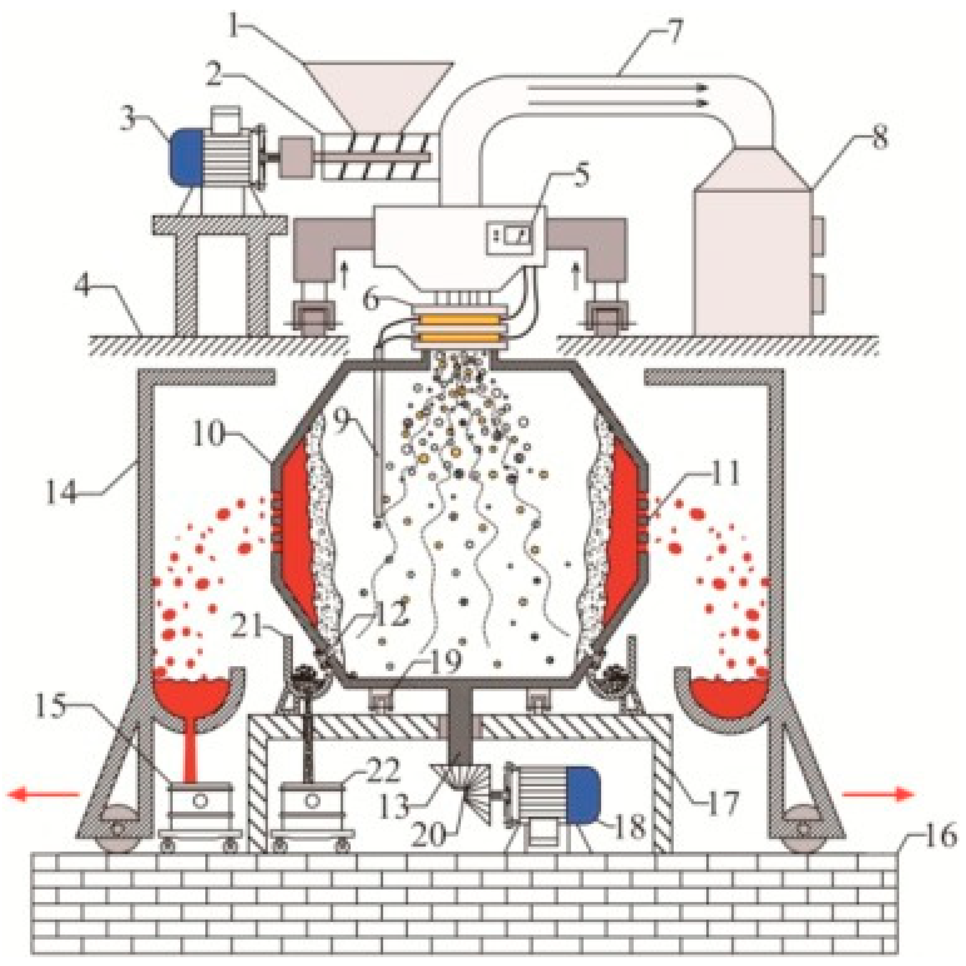
Wastes were reduced in a plasma reactor (with melting points in the range of 1400–1600 °C), resulting in a glassy slag phase with more leaching resistance than conventional glasses. A plasma arc centrifugal treatment (PACT) system treats waste material that is fed into a sealed and water-cooled primary chamber through an air-locked system (Figure 8). A plasma torch melts the material and converts it into slag, which is collected from each subsequent interval. The rotational speed of a PACT system in the range of 15–50 rpm allows a faster speed of the materials in the system and uniform melting. Another advantage of the centrifuge system is the improved homogenization. The force exerted by the momentum of the plasma gas on the bath surface depresses the surface at the point of impingement. This process repeats 15 to 50 times per minute for the effective processing of waste material. The chemical composition of vitrified slag is uniform after molten slag cools in the mold, with small crystallite of glassy phase in the slag product. The PACT system contains a refractory liner that allows no leakage of hazardous gases to the surroundings and reduces heat loss. Since the centrifuge provides one axis of motion, the torch is usually provided with two-axis, servo-controlled positioning. Feeding chambers have isolation valves at both the inlet and outlet positions that can control any leakage from the chamber to the environment [35,36,37]. The gas/slag chamber is also air-locked for introducing molds or removing slag. The safety mold is lined with refractory material, thus ensuring a safe operation of melting inside the chamber [36,37,38]. PACT systems have been implemented for vitrifying nuclear waste in various countries, such as the USA, Switzerland, and Japan.
4.3. Thermal Plasma Processing of Red Mud for Recovery of Valuable Metals
Red mud is the residual chemical waste generated in the bauxite industry from alumina production. The huge quantity of waste generated during the chemical process is alkaline in nature, and disposal to the surrounding environment creates health hazards. Red mud contains various metals, with a major quantity of iron in metal and compound form [39,40]. Thermal plasma treatment for recovery of metal from red mud not only contributes to the strategy, when considering red mud as a resource, but it also will contribute less to land and health contamination. DC extended arc plasma has been implemented in the reduction of red mud toward value-added iron byproducts. Mud powder was used to recover iron. Graphite was used as a reductant with the combination of lime and low-ash coke for the reduction of red mud. In the approach of a statistical model, there is a chance of more than 75% metal recovery using a thermal plasma source [41]. The sequences of the reduction process are formulated below as a set of equations:
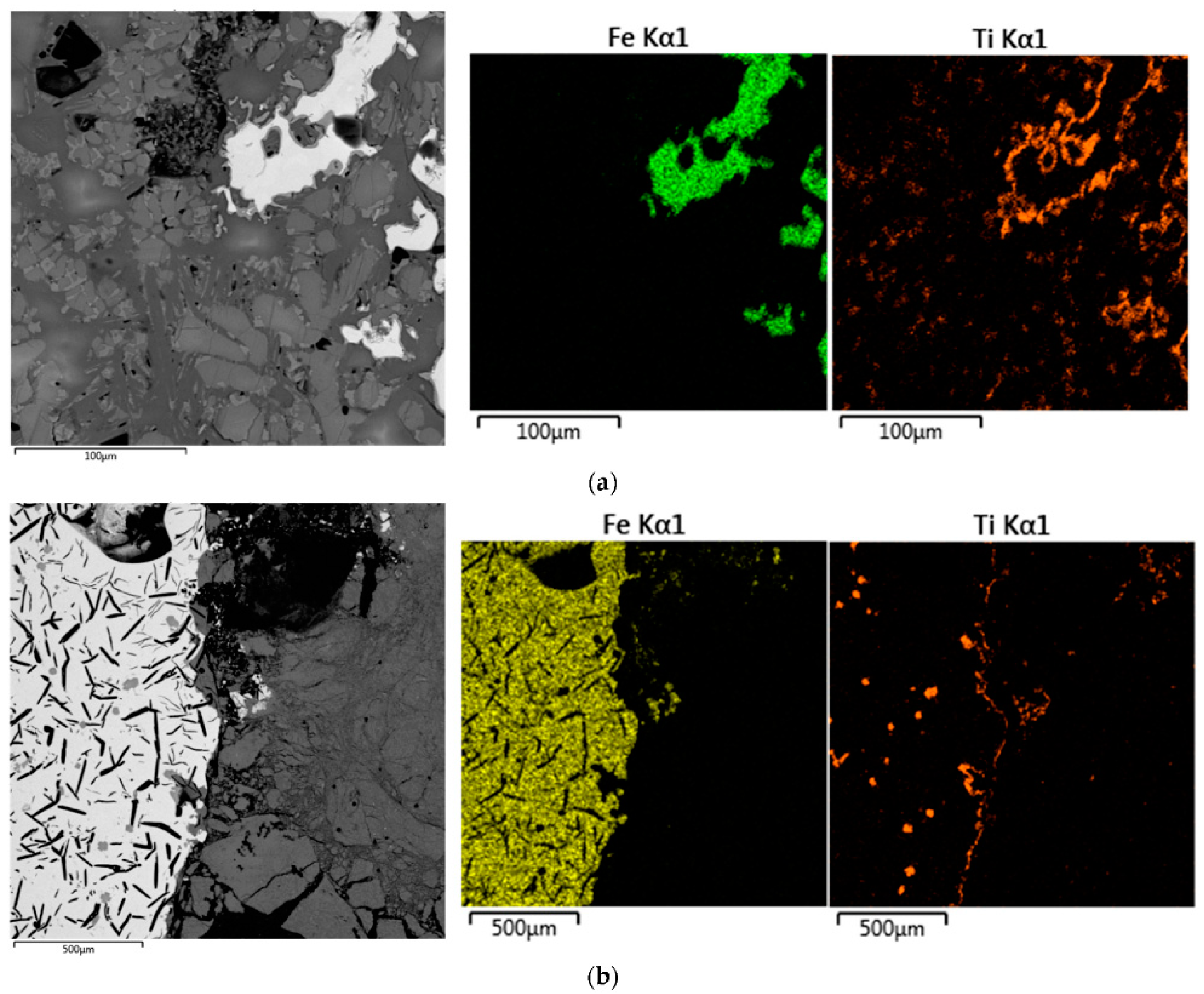
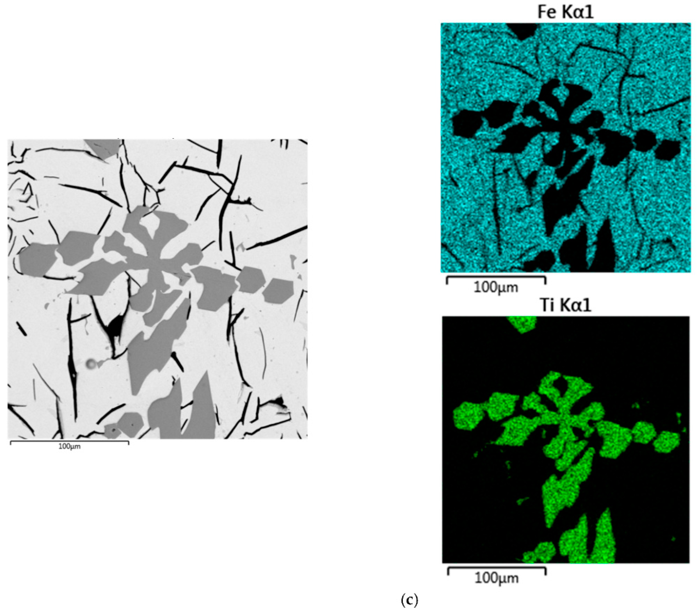
As red mud contains 30 to 50% iron, it undergoes a smelting reduction in a 35 kW DC extended arc thermal plasma reactor. The maximum iron recovery was 71% at an optimum smelting time of about 15 min for 350 g batch [42]. Figure 9 shows an SEM image of pig iron trapped in a reduced slag of red mud by the smelting method. The as-cast microstructures show elongated graphitic flakes dispersed in the Fe matrix (Figure 9a). In Figure 9b, an etched SEM image of an interdendritic eutectic mixture of pearlite and cementite is shown.
4.4. Thermal Plasma Processing of Minerals and Ores for Recovery of Metals
Thermal plasma covers a wide area in the field of mineral and ore processing in the metallurgical industry. The use of transferred and nontransferred arc plasma allows the decomposition of minerals to recover zirconia metals [43].
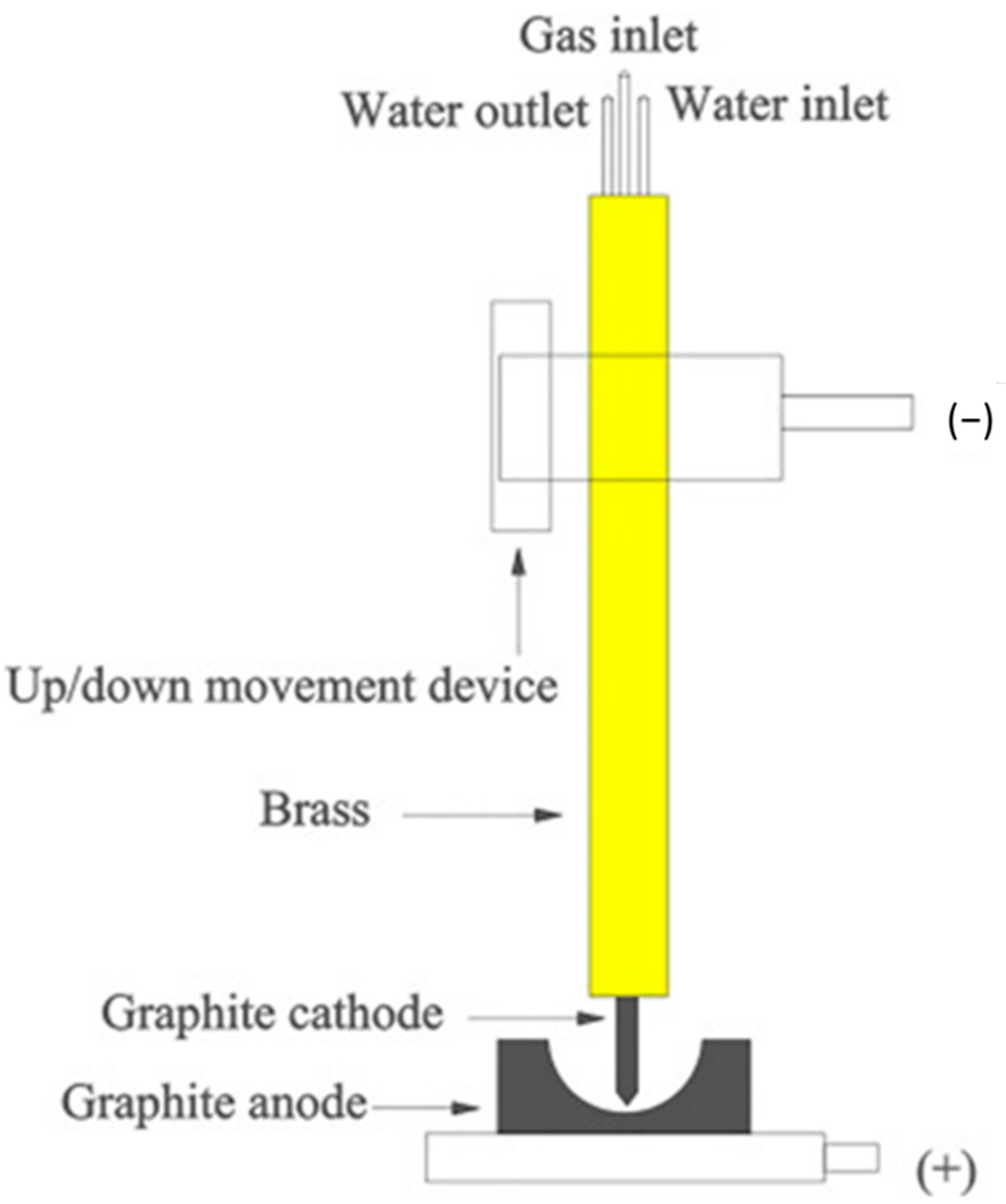
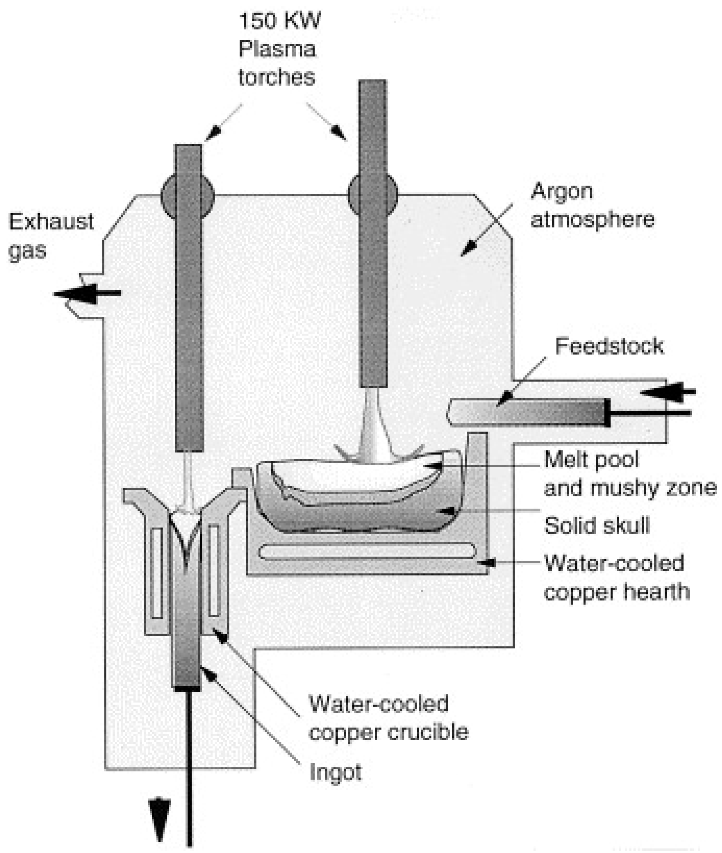
In order to proceed with zirconia recovery at low power and with a short treatment time, a low-power transferred arc plasma torch was employed. A scheme of low power transferred arc plasma is shown in Figure 10. Since the 1970s, plasma arcs have been used for recovering titanium scrap and the refining of metals, as economic value, such as the cost, is associated with base metal recovery. In the steel industry, electric arc furnaces (EAF) are widely used, and release polluted air into the surrounding areas. The plasma process has been used commercially for recovering iron and zinc from EAF dust, and for recovering aluminum from the dross generated in aluminum production, and copper alloy from brass foundry dross [44,45]. Thermal plasma is used for making titanium alloy ingots, nickel-based powders, niobium-based superconducting alloys, and several other special metal applications [36,46]. The mechanism for making ingots is represented in Figure 11 [39]. It consists of a water-cooled copper-melting hearth and water-cooled withdrawal crucibles.
Thermal plasma is also employed in material-processing industries for various phases such as metal extraction, metal refining, and alloying. Ilmenite is the major mineral resource for titanium, with the compound titanium dioxide used as white pigment in the pigment industry. Titanium dioxide pigment is used for white coloration of paints, plastics, and papers. Synthetic rutile (TiO2), which contains TiO2 in the order of 92–96%, can be produced from Ti-rich slag by various chemical routes. The more productive one is subjected to raw ilmenite, and undergoes thermal reduction treatment with the complete convertion of the iron oxide complex to a simpler form, followed by leaching with acid. The smelting process uses coal as reductant with ilmenite for reduction into titania-rich slag with 75–85% of TiO2 content. The technology of thermal plasma reduction has been implemented in various countries, such as Canada, South Africa, the USA, Malaysia, and India [47,48]. Transferred arc plasma technology can be used for metallurgical processing. DC thermal plasma reactors offer unique advantages for reduction processes such as high heat flux densities, with rapid start-up and shutdown times [49]. The thermal plasma process is energy-intensive; hence, slag production in countries using electric power is costly, and is not advisable. The chemical process generates a large amount of wastes that are not ecofriendly in nature, and as a result, thermal plasma has emerged as an alternative route for the production of valuable byproducts. Ilmenite (FeO.TiO2) is a mineral with a melting point of 1392 °C. The solid-state reaction process in thermal plasma chambers undergoes a reduction process for the formation of oxides of iron and titanium phases, as shown below:
At temperatures around 1600–1700 °C, the electrothermal smelting reaction process initiates a reaction between ilmenite and reductant carbon in the formation of FeO (10–20%), Ti2O3, and TiO. A maximum value of 85–87% TiO2 content was produced in the slag by the thermal plasma process. The minor oxide components of Al2O3, MgO, and CaO remained the same in the slag after the reduction process.
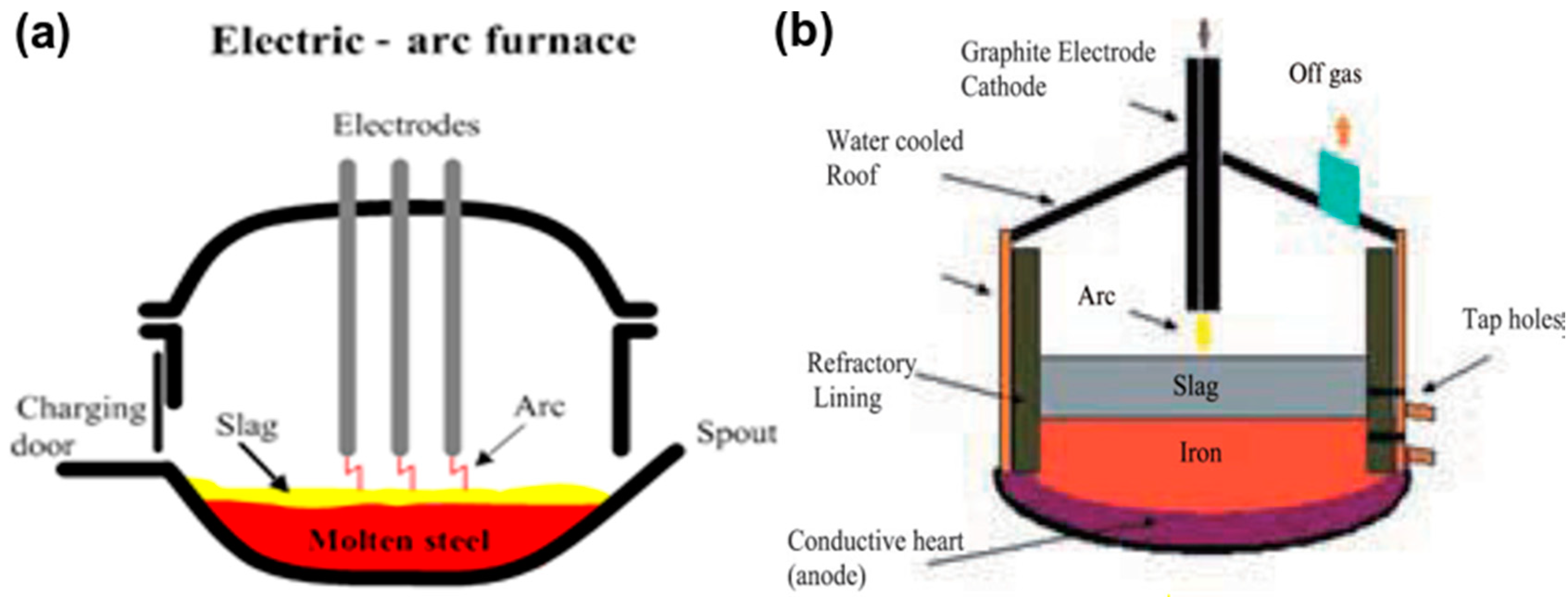
AC and DC furnaces are used for smelting of ilmenite ore. Schematic diagrams of AC and DC arc furnaces are shown in Figure 12 [46].
The parts of an AC arc furnace are the foundation, shell, chamber, bottom, and feeder. The powder is inserted by the feeder system into the chamber of the furnace. The plasma arc is established by the charging system from the rooftop. A tapping port is connected at the bottom for slag/metal collection. An electrode device, transformers with controllers for power supply and cooling, and a ventilation system are arranged in the furnace system. Three to six electrodes of the self-baking type are involved to supply electric power to the furnace system [50,51,52]. However, the two-electrode system is based on a DC furnace. The cathode and anode belong to the inside part of the system, such as the bottom of the furnace, with conducting melt forming the anode, and a hollow centrally placed electrode acting as the cathode (Figure 12b). Ilmenite and the coal mixture, along with the carrier gas, is fed into a plasma flame through the anode. This furnace can realize a more efficient energy transfer in comparison to an AC furnace. MINTEK, South Africa used a DC furnace. A water-cooled plasma arc torch was implemented in transferred mode for smelting ferrochromium. An electric arc furnace was used in Australia for smelting sand ilmenite. QIT, Canada implemented a carbothermic reduction process for making TiO2-rich slag [53,54]. Thermal plasma melting of ilmenite separated titania and iron into the forms of titania-rich slag and metallic iron, respectively. TiO2 content in the slag varied from 75–85%, whereas iron content was in the range of 10–20% in the slag. The energy consumption was found to be about 3–4 kWh for smelting 21 kg of ilmenite to slag in a static bed DC plasma reactor. However, one additional step of using metallized ilmenite reduced energy consumption significantly in the DC plasma reactor.
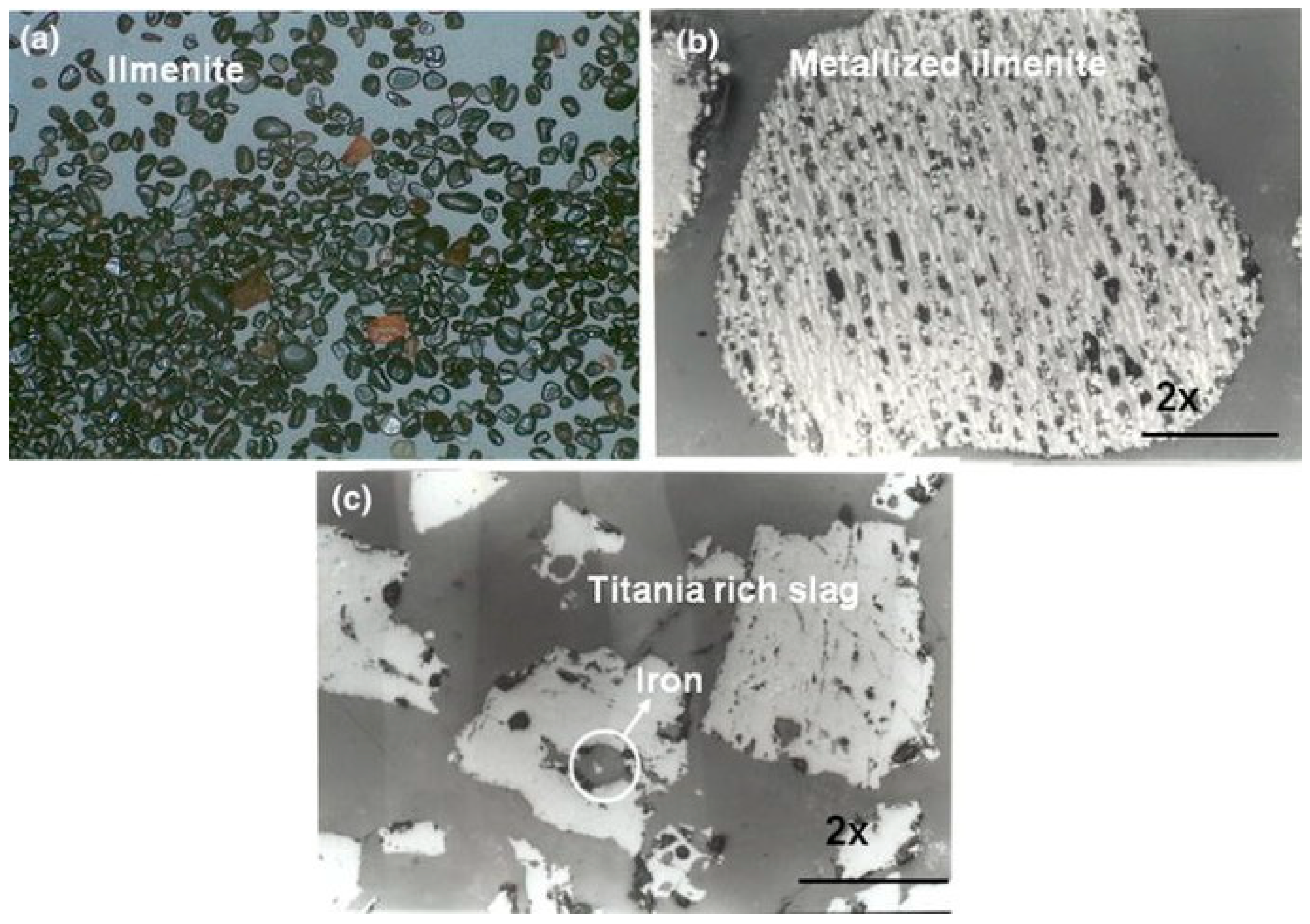
Figure 13 shows optical microscope images of ilmenite grains, as well as an enlarged view of the metallized ilmenite and slag produced by a thermal plasma process. Ilmenite shows grains of sand particles; in the carbothermal reduction process, it coverts into metallized ilmenite. In the metallized complex, Fe converts into a simpler form of oxide. Thermal plasma processing reduced the metallized ilmenite into Ti-rich slag, with accumulating iron as the bulk form in the slag that could be separated easily from the slag. After the separation of metallic iron, the remaining Ti-rich slag is one of the sources for the TiO2 pigment for industries [54].
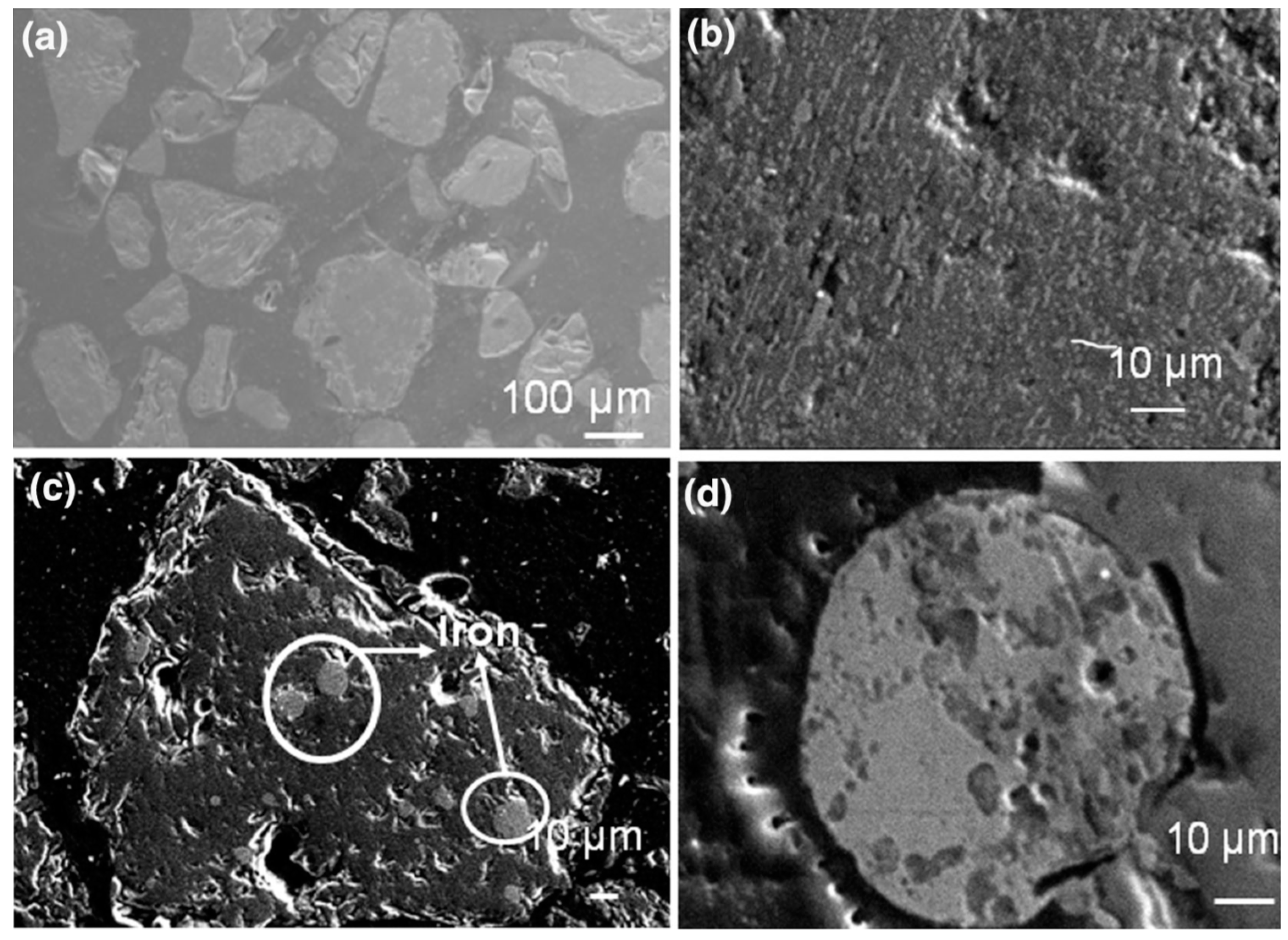
Figure 14 displays a scanning electron micrograph of polished ilmenite particles with metallized ilmenite after the reduction process. Figure 14c,d show titania-rich slag, with iron entrapped with bulk iron in the more magnified image. This is one of the examples of thermal plasma processing of minerals for extraction of metals. Ilmenite dissociates into oxides of titanium and iron phases. The thermal plasma reduction process converts the iron oxide (FeO) into elemental iron (Fe) from titania-rich slag [55].
4.5. Thermal Plasma Reduction of Minerals toward Nanoparticles of Oxide
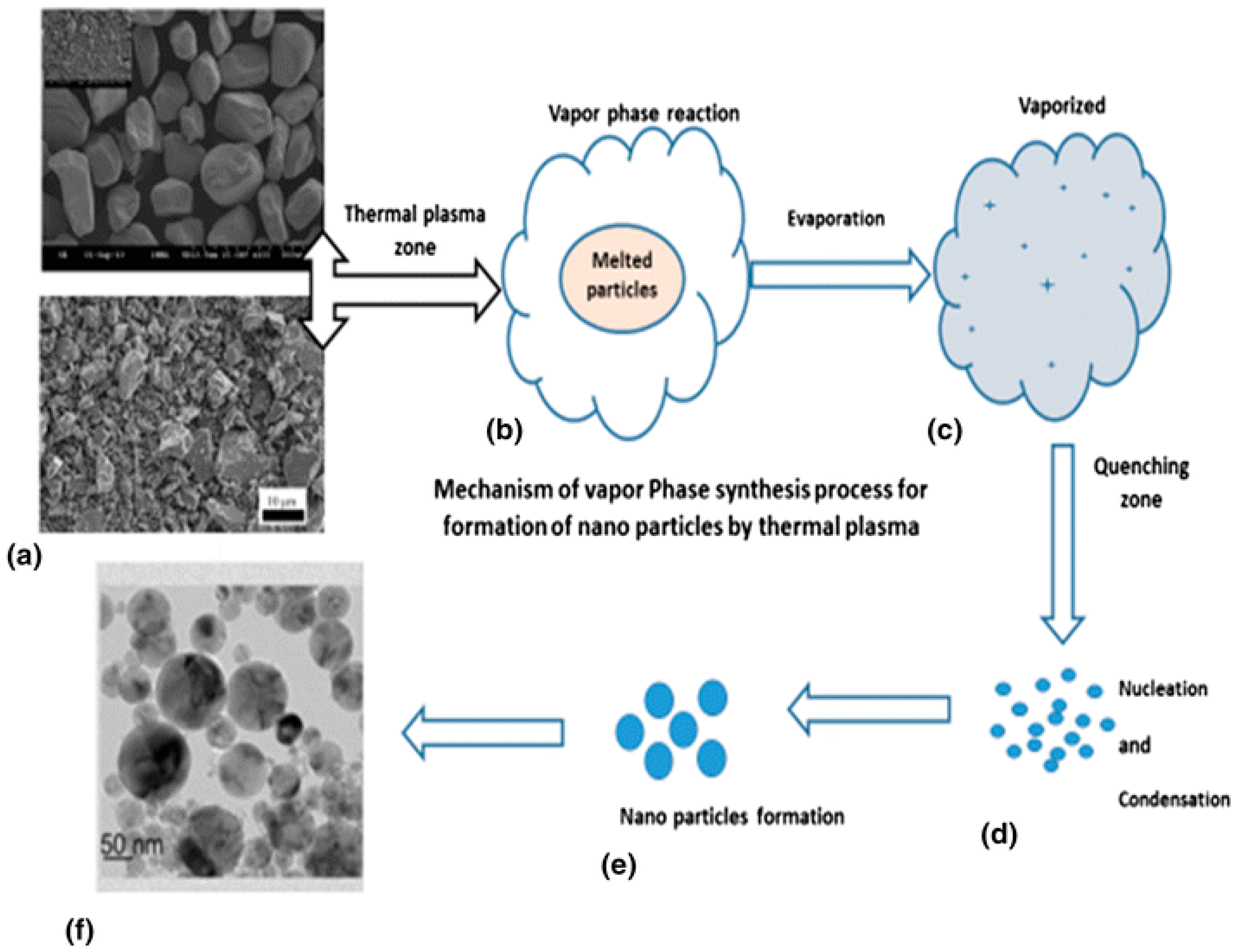
Recently, there has been an increasing trend toward the preparation of nanoparticles by using thermal plasma technology. Various resources such as minerals and bulk particles are considered as feedstock materials for decomposition and size reduction in nanoparticle formation. Nano-TiO2 particles have been generated from minerals by the vapor phase reduction method using a nontransferred arc thermal plasma reactor. This process allows dissociation of complex mineral and iron separation, with production of TiO2 nanoparticles as a byproduct. Figure 15 depicts a scheme of the processing method by thermal plasma, with the initial and final product.
In addition, low-dimensional nanomaterials are one step ahead of various materials made by thermal plasma methods such as glass and alloys [15,54]. Plasma spheroidization, which allows an easy synthesis of nanoparticles attached to spherical alloy powder, is carried out by vaporization and condensation of raw powder, which undergoes a steep variation in temperature [54,55]. Spherical powder prepared by thermal plasma synthesis is not only used for powder metallurgy or additive manufacturing, but also as materials in the process synthesis of furnished coatings for surface protection [56].
5. Discussion
Thermal plasma technology has played a significant role in industrial applications, including waste material reduction, materials processing, nanopowder synthesis, deposition of functional coatings, waste treatment, metal recovery from wastes and minerals, and biomass gasification. The thermal plasma source is an integral part of the process, and is a technology for achieving various needs in the increasing demand for applications on a pilot-scale basis [57,58,59]. Waste treatment by thermal plasma technology has emerged as a value-added product. Plasma technology offers principal advantages in comparison to other existing technologies for the reduction of exhaust gas flow rates, volume reduction, lower investment costs, and faster start-up and shutdown times. Based on the above findings, it is clear that plasma gasification can decompose polypropylene granules and produce a desirable composition of syngas. Syngas could used by industries for production of heat and electricity; liquid fuel production; or for chemical products such as hydrogen, ammonia, and methanol [60,61,62]. Polypropylene granules, being the representative of plastic wastes, show the feasibility of plasma gasification to convert end-of-life plastics into commercial products with high value, and subsequently contributing to sustainable economic development [63,64]. Plasma could play a resourceful role in both the fields of waste management and energy production due to its ability to decompose waste, recover energy, and transform waste into commercial products. Plasma technology offers waste-to-energy conversion from an environmental perspective, as plasma systems could be able to decompose a wide range of waste materials and reduce hazardous emissions, due to the process occurring at high temperatures compared to the conventional methods [65]. From a social perspective, it is important to install plasma facilities in proximity to populated regions to promote better acceptance of the technology in society. In addition, some of the plasma systems enable the yielding of a vitrified slag from the inorganic components, such as ash and metals, which could be further analyzed as potential valuable byproducts.
6. Conclusions
An overview of thermal plasma systems for waste treatment and metal recovery has been presented in this article. A basic understanding of thermal plasma mechanism and its application in various areas in the category of green technologies was presented here. Various types of plasma and implications toward an environmentally friendly approach to solving the problems were covered. Thermal plasma has specific advantages over combustion systems. Energy flux and the oxygen potential are not independent of temperature in a thermal plasma system. This technique, while costly due to the energy consumption of electric resources, offers a zero-waste approach to waste-disposal problems. Thermal plasma technology recovers the valuable metal resources from the minerals before discarding them as wastes to the surrounding environment. Economically, this technology contributes resources to industrial application while minimizing pollutants and wastes.
Funding
This research received no external funding.
Data Availability Statement
Not applicable.
Acknowledgments
The first author would like to acknowledgment project Solid-21 for the support within the Institute of Physics, Prague, Czech Republic (SOLID21: CZ.02.1.01/0.0/0.0/16_019/0000760, SOLID21-Fyzika pevných látek pro 21. Století, Fyzikální ústav AV ČR, v. v. i. (2018–2023).
Conflicts of Interest
The authors declare no conflict of interest.
References
- Samal, S. Thermal plasma technology: The prospective future in material processing. J. Clean. Prod. 2017, 142, 3131–3150. [Google Scholar] [CrossRef]
- Punčochář, M.; Ruj, B.; Chatterj, P.K. Development of process for disposal of plastic waste using plasma pyrolysis technology and option for energy recovery. Procedia Eng. 2012, 42, 420–430. [Google Scholar] [CrossRef] [Green Version]
- Samal, S. Utilization of Red Mud as a Source for Metal Ions—A Review. Materials 2021, 14, 2211. [Google Scholar] [CrossRef] [PubMed]
- Mombelli, D.; Barella, S.; Gruttadauria, A.; Mapelli, C. Iron Recovery from Bauxite Tailings Red Mud by Thermal Reduction with Blast Furnace Sludge. Appl. Sci. 2019, 9, 4902. [Google Scholar] [CrossRef] [Green Version]
- Samal, S.; Molnárová, O.; Průša, F.; Kopeček, J.; Heller, L.; Šittner, P.; Škodová, M.; Abate, L.; Blanco, I. Net-Shape NiTi Shape Memory Alloy by Spark Plasma Sintering Method. Appl. Sci. 2021, 11, 1802. [Google Scholar] [CrossRef]
- Samal, S. Synthesis of TiO2 nanoparticles from ilmenite through the mechanism of vapor-phase reaction process by thermal plasma technology. J. Mater. Eng. Perform. 2018, 27, 2622–2628. [Google Scholar] [CrossRef]
- Ramachandran, K.; Kikukawa, N. Plasma in-flight treatment of electroplating sludge. Vacuum 2000, 59, 244–251. [Google Scholar] [CrossRef]
- Cortez, R.; Zaghloul, H.H.; Stephenson, L.D.; Smith, E.D.; Wood, J.W.; Cahil, D.G. Laboratory Scale Thermal Plasma Arc Vitrification Studies of Heavy Metal-Laden Waste. J. Air Waste Manag. Assoc. 1996, 46, 1075–1080. [Google Scholar] [CrossRef] [Green Version]
- Szałatkiewicz, J. Metals Recovery from Artificial Ore in Case of Printed Circuit Boards, Using Plasmatron Plasma Reactor. Materials 2016, 9, 683. [Google Scholar] [CrossRef] [Green Version]
- Wang, Q.; Yan, J.H.; Chi, Y.; Li, X.D.; Lu, S.Y. Application of thermal plasma to vitrify fly ash from municipal solid waste incinerators. Chemosphere 2010, 78, 626–630. [Google Scholar] [CrossRef]
- Mombelli, D.; Mapelli, C.; Barella, S.; Gruttadauria, A.; Agona, M.R.; Pisu, M.; Viola, A. Characterization of cast iron and slag produced by red muds reduction via Arc Transferred Plasma (ATP) reactor under different smelting conditions. J. Environ. Chem. Eng. 2020, 8, 104293. [Google Scholar] [CrossRef]
- Szałatkiewicz, J. Metals content in printed circuit boards waste. Pol. J. Environ. Stud. 2014, 23, 2365–2369. [Google Scholar]
- Mohai, I.; Szépvölgyi, J.; Károly, Z.; Mohai, M.; Toth, M.; Babievskaya, I.Z.; Krenev, V.A. Reduction of Metallurgical Wastes in an RF Thermal Plasma Reactor. Plasma Chem. Plasma Process. 2001, 21, 547–563. [Google Scholar] [CrossRef]
- Samal, S.; Tyc, O.; Cizek, J.; Klecka, J.; Lukáč, F.; Molnárová, O.; de Prado, E.; Weiss, Z.; Kopeček, J.; Heller, L.; et al. Fabrication of Thermal Plasma Sprayed NiTi Coatings Possessing Functional Properties. Coatings 2021, 11, 610. [Google Scholar] [CrossRef]
- Cho, S.; Shim, H.; So, K.; Kim, S.; Samal, S.; Park, D.; Kim, H. Synthesis of nanosized glass powders using non-transferred dc thermal plasma process. Adv. Appl. Ceram. 2013, 112, 288–293. [Google Scholar] [CrossRef]
- Samal, S.; Park, D.W. Nano-particle synthesis of titanium oxides from ilmenite in a thermal plasma reactor. Chem. Eng. Res. Des. 2012, 90, 548–554. [Google Scholar] [CrossRef]
- Spores, R.; Pfender, E. Flow Structure of a Turbulent Thermal Plasma Jet. Surf. Coat. Technol. 1989, 37, 251–270. [Google Scholar] [CrossRef]
- Pfender, E.; Fincke, J.; Spores, R. Entrainment of Cold Gas into Thermal Plasma Jets. Plasma Chem. Plasma Process 1991, 11, 529–543. [Google Scholar] [CrossRef]
- Taylor, P.R.; Pirzada, S.A. Thermal plasma processing of materials: A review. Adv. Perform. Mater. 1994, 1, 35–50. [Google Scholar] [CrossRef]
- Brossa, M.; Pfender, E. Probe Measurements in Thermal Plasma Jets. Plasma Chem. Plasma Process. 1988, 8, 75–90. [Google Scholar] [CrossRef]
- Capetti, A.; Pfender, E. Probe Measurements in Argon Plasma Jets Operated in Ambient Argon. Plasma Chem. Plasma Process. 1989, 9, 329–341. [Google Scholar] [CrossRef]
- Samal, S.; Kim, D.W.; Kim, K.S.; Park, D.W. Direct synthesis of TiO2 nanoparticles by using the solid-state precursor TiH2 powder in a thermal plasma reactor. Chem. Eng. Res. Des. 2012, 90, 1074–1081. [Google Scholar] [CrossRef]
- Samal, S. Thermal Plasma Processing of Materials: High Temperature Applications. In Encyclopedia of Materials: Metals and Alloys; Caballero, F.G., Ed.; Elsevier: Oxford, UK, 2022; Volume 1, p. 512. [Google Scholar]
- Mukherjee, P.S.; Samal, S.; Mukherjee, T.K. In-flight thermal plasma processing of pre-reduced ilmenite. Trans. Indian Inst. Met. 2006, 59, 353–358. [Google Scholar]
- Young, R.M.; Pfender, E. A Novel Approach for Introducing Particulate Matter into Thermal Plasmas: The Triple-Cathode Arc. Plasma Chem. Plasma Process. 1989, 9, 465–481. [Google Scholar] [CrossRef]
- Lee, S.; Lee, J.; Kim, W.; Hwang, N.-M. Plasma Etching Behavior of YOF Coating Deposited by Suspension Plasma Spraying in Inductively Coupled CHF3/Ar Plasma. Coatings 2020, 10, 1023. [Google Scholar] [CrossRef]
- Chyou, Y.P.; Pfender, E. Behavior of Particulates in Thermal Plasma Flows. Plasma Chem. Plasma Process. 1989, 9, 45–71. [Google Scholar] [CrossRef]
- Heberlein, J.; Murphy, A. Thermal plasma waste treatment. J. Phys. D Appl. Phys. 2008, 4, 053001. [Google Scholar] [CrossRef]
- Mitrasinovic, A.; Pershin, L.; Wen, J.Z.; Mostaghimi, J. Recovery of Cu and Valuable metals from E-waste using thermal plasma treatment. JOM 2011, 63, 24. [Google Scholar] [CrossRef]
- Samal, S. Introduction and Preview. In Thermal Plasma Processing of Ilmenite; Springer Briefs in Applied Sciences and Technology; Springer: Cham, Switzerland, 2018. [Google Scholar] [CrossRef]
- Szałatkiewicz, J.; Szewczyk, R.; Budny, E.; Missala, T.; Winiarski, W. Construction aspects of plasma based technology for waste of electrical and electronic equipment (WEEE) management in urban areas. Proc. Eng. 2013, 57, 1100–1108. [Google Scholar] [CrossRef] [Green Version]
- Rath, S.S.; Jayasankar, K.; Satapathy, B.K.; Mishra, B.K.; Mukherjee, P.S. Kinetics and statistical behaviour of iron recovery from red mud using plasma arc furnace. High Temp. Mater. Proc. 2011, 30, 211–215. [Google Scholar] [CrossRef]
- Bidini, G.; Fantozzi, F.; Bartocci, P.; D’Alessandro, B.; D’Amico, M.; Laranci, P.; Scozza, E.; Zagaroli, M. Recovery of precious metals from scrap printed circuit boards through pyrolysis. J. Anal. Appl. Pyrolysis 2015, 111, 140–147. [Google Scholar] [CrossRef]
- Rath, S.S.; Pany, A.; Jayasankar, K.; Mitra, A.K.; Kumar, C.S.; Mukjerjee, P.S. Statistical modeling studies of iron recovery from red mud using thermal plasma. Plasma Sci. Technol. 2013, 15, 459. [Google Scholar] [CrossRef]
- Valeev, D.; Zinoveev, D.; Kondratiev, A.; Lubyanoi, D.; Pankratov, D. Reductive Smelting of Neutralized Red Mud for Iron Recovery and Produced Pig Iron for Heat-Resistant Castings. Metals 2020, 10, 32. [Google Scholar] [CrossRef] [Green Version]
- Yugeswaran, S.; Ananthapadmanabhan, P.V.; Lusvarghi, L. Zircon dissociation in air plasma through a low power transferred arc plasma torch. Ceram. Int. 2015, 41, 265–273. [Google Scholar] [CrossRef] [Green Version]
- Zunkel, A.D. Electric Arc Fumace Dust management: A review of technologies. Iron Steel Eng. 1997, 74, 3. [Google Scholar]
- Drouet, M.G. High temperature processes for industrial waste treatment and valorisation. In Conference Proceedings—Italian Physical Society; Editrice Compositori: Bologna, Italy, 1993; p. 77. [Google Scholar]
- Hoffeiner, W.; Eschenbach, R.C. Treatment of Processing Waste with Thermal Plasma. In Proceedings of the 1994 TMS Annual Meeting, San Francisco, CA, USA, 28 February–3 March 1994. [Google Scholar]
- Meng, L.; Zhong, Y.; Guo, L.; Wang, Z.; Chen, K.; Guo, Z. High temperature centrifugal separation of Cu from waste printed circuit boards. J. Clean. Prod. 2018, 199, 831–839. [Google Scholar] [CrossRef]
- Godfrey, B.; Loretto, M.H. Origins of heterogeneities in plasma melted ingots of γ-TiAl. Mater. Sci. Eng. A 1999, 266, 115–122. [Google Scholar] [CrossRef]
- Balliett, R.W. A New Plasma Arc Furnace with Helium Recycle and Purification. In Proceedings of the 1991 Vacuum Metallurgy Conference on the Melting and Processing of Specialty Materials, Pittsburgh, PA, USA, 9 September 1991. [Google Scholar]
- Eschenbach, R.C. Plasma arc systems for waste treatment and metal recovery. JOM 1996, 48, 49–52. [Google Scholar] [CrossRef]
- Stenkvist, S.E.; Bowman, B. High-power, graphite-cathode DC arc plasma properties and practical applications for steelmaking and ferroalloys processing. In Plasma Technology in Metallurgical Processing; The Iron and Steel Society of AIME: Warrendale, PA, USA, 1987; Chapter 8B; pp. 103–109. [Google Scholar]
- Curr, T.R.; Barcza, N.A.; Maske, U.K.; Mooney, J.F. The design and operation of transferred-arc plasma systems for pyrometallurgical applications. In Proceedings of the 6th International Symposium on Plasma Chemistry, Montreal, QC, Canada, 24–28 July 1983; Volume 1, pp. 175–180. [Google Scholar]
- Samal, S.; Mukherjee, P.S.; Mukherjee, T.K. Thermal plasma processing of ilmenite: A review. Trans. Inst. Min. Metall. Sect. C 2010, 119, 116–123. [Google Scholar] [CrossRef]
- Barcza, N.A.; Curr, T.R.; Jones, R.T. Metallurgy of open-bath plasma processes. Pure Appl. Chem. 1990, 62, 1761–1772. [Google Scholar] [CrossRef]
- Bester, J.A.; de Beer, J.A.; Rohwer, H.E. Metallic zirconium production by hydrogen reduction of ZrCl4 in a transferred arc torch. In Proceedings of the 2nd European Congress on ‘Thermal Plasma Processes’, Paris, France, 7–9 September 1992. [Google Scholar]
- Schoukens, A.F.S.; Curr, T.R. The production of manganese ferroalloys in transferred-arc plasma systems. In Proceedings of the 41st Electric Furnace Conference, Pittsburgh Meeting, Warrendale, PA, USA, 28–31 March 1982; The Iron and Steel Society, AIME: London, UK, 1982; pp. 161–171. [Google Scholar]
- Muller, H.G.; Koch, E.; Dosaj, V.D.; Wellbeloved, D. Examples of plasma potential for industrial application. In Proceedings of the ISPC-9 Workshop on ‘Industrial Plasma Applications’, Pugnochiuso, Italy, 9–10 September 1989; Volume 2, p. 50. [Google Scholar]
- Samal, S. Synthesis and characterization of Titanium slag from ilmenite by thermal plasma processing. JOM 2016, 68, 2349–2358. [Google Scholar] [CrossRef]
- Samal, S.; Mohapatra, B.K.; Mukherjee, P.S.; Chatterjee, S.K. Integrated XRD, EPMA and XRF study of ilmenite and titania slag used in pigment production. J. Alloys Compd. 2009, 474, 484–489. [Google Scholar] [CrossRef]
- Kim, K.S.; Kim, T.H. Nanofabrication by thermal plasma jets: From nanoparticles to low-dimensional nanomaterials. J. Appl. Phys. 2019, 125, 070901. [Google Scholar] [CrossRef] [Green Version]
- Fu, Z.; Hao, Z.; Che, Y.; Shu, Y.; He, J. Facile synthesis of nano-particles attached spherical Ti-6Al-4V powder based on plasma spheroidization. J. Alloys Compd. 2021, 858, 158313. [Google Scholar] [CrossRef]
- Zhu, H.; Tong, H.; Yang, F.; Cheng, C. Plasma-assisted preparation and characterization of spherical stainless steel powders. J. Mater. Process. Technol. 2018, 252, 559–566. [Google Scholar] [CrossRef]
- Maric, R.; Fukui, T.; Ohara, S.; Yoshida, H.; Nishimura, M.; Inagaki, T.; Miura, K. Powder prepared by spray pyrolysis as an electrode material for solid oxide fuel cells. J. Mater. Sci. 2000, 35, 1397–1404. [Google Scholar] [CrossRef]
- Mostaghimi, J.; Boulos, M.I. Thermal Plasma Sources: How Well are They Adopted to Process Needs? Plasma Chem. Plasma Process. 2015, 35, 421–436. [Google Scholar] [CrossRef]
- Bendix, D.; Hebecker, D. Energy recovery from waste and plasma conversion. High Temp. Mater. Process. Int. Q. High-Technol. Plasma Process. 2003, 7, 435–454. [Google Scholar] [CrossRef]
- Suzuki, M.; Ichihashi, T.; Jote, A.; Nishio, S.; Kawagoe, S. Application of reactive plasma to nuclear waste treatment—Possibility of separation of Zr–Nb alloy by reactive thermal plasma treatment. High Temp. Mater. Process. Int. Q. High-Technol. Plasma Processes 2003, 7, 475–485. [Google Scholar] [CrossRef]
- Suzuki, M.; Kadowaki, M.; Windarto, H.; Mori, S. Comparison of different types of plasma in radioactive decontamination process. Mater. Sci. Forum 2005, 502, 321–326. [Google Scholar] [CrossRef]
- Fiedler, J.; Lietz, E.; Bendix, D.; Hebecker, D. Experimental and numerical investigations of a plasma reactor for the thermal destruction of medical waste. J. Phys. D Appl. Phys. 2004, 37, 1031–1040. [Google Scholar] [CrossRef]
- Murphy, A.B.; Farmer, A.J.D.; Horrigan, E.C.; McAllister, T. Plasma destruction of ozone depleting substances. Plasma Chem. Plasma Process. 2002, 22, 371–385. [Google Scholar] [CrossRef]
- Sekiguchi, H.; Honda, T.; Kanzawa, A. Thermal plasma decomposition of chlorofluorocarbons. Plasma Chem. Plasma Process. 1993, 13, 463–478. [Google Scholar] [CrossRef]
- Chapman, C.D.; Cowx, P.M. Tetronics process for the treatment of electric arc furnace dust. Steel Times 1991, 219, 301–304. [Google Scholar]
- Mustoe, T.N.; Liang, F.W. The power of plasma: Commercialization and the environment. In Proceedings of the International Conference Incineration and Thermal Treatment Technologies, Orlando, FL, USA, 10–14 May 1999. [Google Scholar]
Figure 1.
Schematic diagrams of: (a) transitional plasma jet; (b) rotational flow jet. Reprinted from [17] with permission from Elsevier 1989.
Figure 1.
Schematic diagrams of: (a) transitional plasma jet; (b) rotational flow jet. Reprinted from [17] with permission from Elsevier 1989.

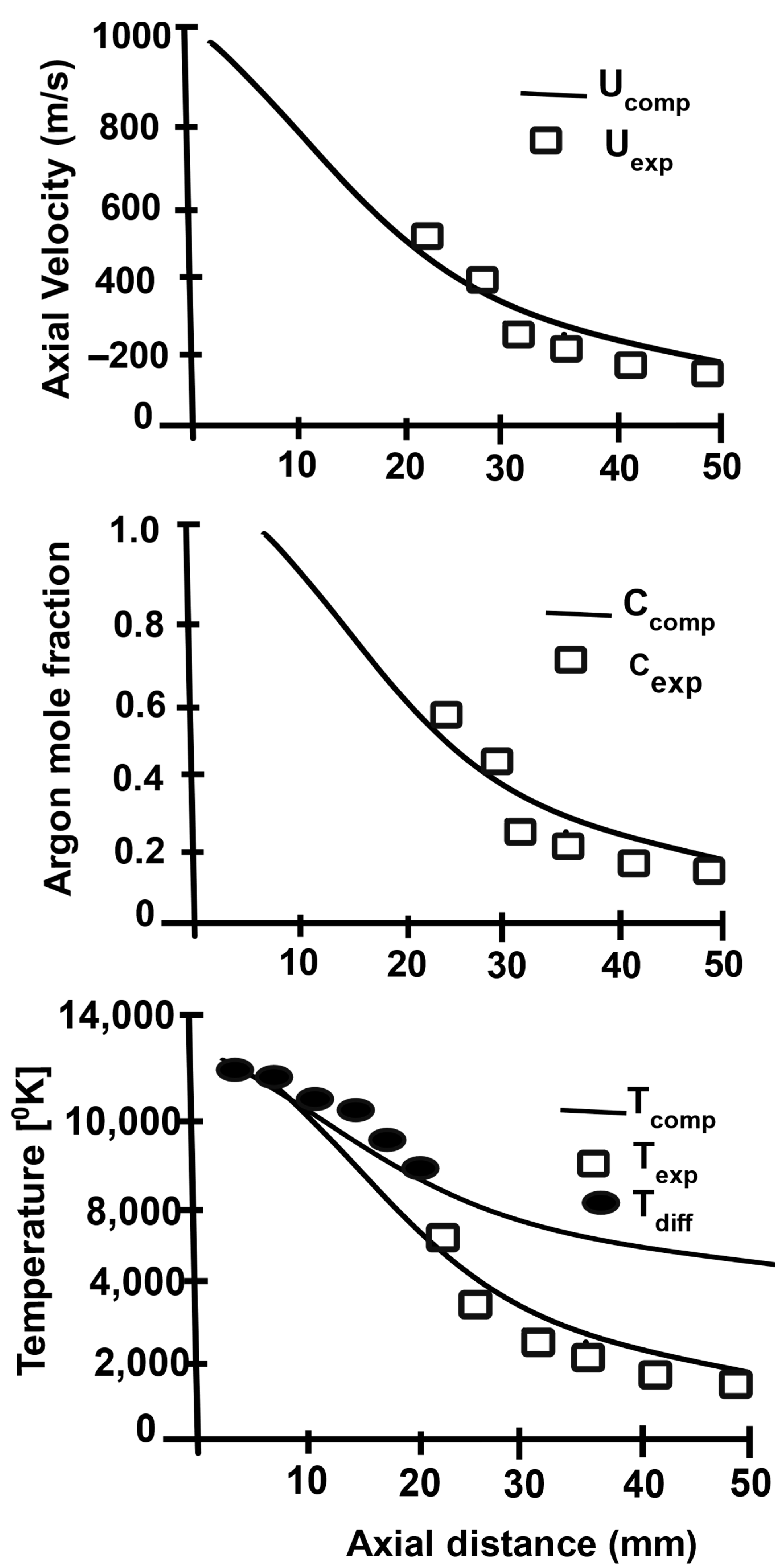
Figure 2.
Comparison of calculated centerline fields with experimental data. Reprinted from [18] with permission from Springer 1991.
Figure 2.
Comparison of calculated centerline fields with experimental data. Reprinted from [18] with permission from Springer 1991.

Figure 3.
Schematic diagrams of: (a) nontransferred system; (b) nontransferred plasma reactor. Reprinted from [21] with permission from Elsevier 1989.
Figure 3.
Schematic diagrams of: (a) nontransferred system; (b) nontransferred plasma reactor. Reprinted from [21] with permission from Elsevier 1989.

Figure 4.
Schematic diagrams of (a) the transferred arc and (b) the corresponding plasma reactor. Reprinted from [1] with permission from Elsevier 2016. 1—Rack and pinion; 2—electrode holder with water cooling; 3—gas exhaust outlet; 4—alumina bush with graphite sleeve; 5—viewing port; 6—water-cooled steel cover; 7—Furnace hearth; 8—graphite electrode; 9—bubble alumina; 10—water-cooled steel coating; 11—graphite crucible; 12—graphite wool; 13—water-cooled graphite electrode; 14—plasma; 15—graphite block; 16—magnesia block; 17—alumina block; 18—supporting structure.

Figure 5.
Scheme of an extended plasma reactor. Reprinted from [1] with permission from Elsevier 2016. 1—plasma arc; 2—magnesia coating; 3—graphite crucible; 4—bubble alumina; 5—M.S. casing; 6—tap hole; 7—alumina bush; 8—bottom graphite electrode; 9—water inlet; 10—water outlet; 11—outlet for exhaust gases; 12—graphite sleeve; 13—top graphite electrode; 14—axial hole; 15—copper block; 16—plasma-forming gas; 17—electrical insulation; 18—rack and pinion mechanism; 19—hopper.

Figure 6.
Schematic of a triple-torch plasma reactor. Reprinted from [26].
Figure 6.
Schematic of a triple-torch plasma reactor. Reprinted from [26].

Figure 7.
Flow chart of the plasma treatment of e-waste. Reprinted from [9] with permission from Elsevier 2016.
Figure 7.
Flow chart of the plasma treatment of e-waste. Reprinted from [9] with permission from Elsevier 2016.

Figure 8.
Schematic diagram of a PACT system. Reprinted from [38] with permission from Elsevier 1993. 1—Hopper; 2—spiral feeding rod; 3—motor; 4—high platform; 5—microwave generator; 6—conductive sliding ring; 7—flue pipe; 8—exhaust gas treatment tower; 9—thermocouples; 10—rotating centrifugal gravity separation reactor; 11—porous filter plate; 12—residue discharge port; 13—axis; 14—liquid metal receiver; 15—metal liquid storage tanks; 16—low foundation platform; 17—rotating centrifugal gravity separation reactor platform; 18—rotating centrifugal gravity separation reactor motor; 19—ring bearings; 20—gear; 21—slag receiver; 22—tailings storage tank.

Figure 9.
SEM images of the slag and pig iron samples: (a) reduction smelting at 1650 °C; (b) reduction smelting at 1750 °C; (c) titanium carbide in pig iron The mappings show the distributions of Fe and Ti. Reprinted from [35].
Figure 9.
SEM images of the slag and pig iron samples: (a) reduction smelting at 1650 °C; (b) reduction smelting at 1750 °C; (c) titanium carbide in pig iron The mappings show the distributions of Fe and Ti. Reprinted from [35].


Figure 10.
Low-pressure arc plasma. Reprinted from [43] with permission from Elsevier 1996.
Figure 10.
Low-pressure arc plasma. Reprinted from [43] with permission from Elsevier 1996.

Figure 11.
A schematic diagram of a two-torch plasma furnace withdrawing an ingot. Reprinted from [39] with permission from Elsevier 1994.
Figure 11.
A schematic diagram of a two-torch plasma furnace withdrawing an ingot. Reprinted from [39] with permission from Elsevier 1994.

Figure 12.
Schemes of (a) AC and (b) DC electric arc furnaces (EAFs). Reprinted from [46] with permission from Taylor & Francis 2010.
Figure 12.
Schemes of (a) AC and (b) DC electric arc furnaces (EAFs). Reprinted from [46] with permission from Taylor & Francis 2010.

Figure 13.
Optical microscope images of: (a) ilmenite; (b) metalized ilmenite; (c) Ti-rich slag with iron metal. Reprinted from [51] with permission from Springer 2016.
Figure 13.
Optical microscope images of: (a) ilmenite; (b) metalized ilmenite; (c) Ti-rich slag with iron metal. Reprinted from [51] with permission from Springer 2016.

Figure 14.
Scanning electron microscope images of: (a) cross-section view of ilmenite grains; (b) enlarged view of metallized ilmenite; (c) plasma product slag; (d) bulk iron. Reprinted from [51] with permission from Springer 2016.
Figure 14.
Scanning electron microscope images of: (a) cross-section view of ilmenite grains; (b) enlarged view of metallized ilmenite; (c) plasma product slag; (d) bulk iron. Reprinted from [51] with permission from Springer 2016.

Figure 15.
Vapor phase reduction synthesis of ilmenite particles toward titanium dioxide nanoparticles by thermal plasma process. Reprinted from [6] with permission of Springer 2018.
Figure 15.
Vapor phase reduction synthesis of ilmenite particles toward titanium dioxide nanoparticles by thermal plasma process. Reprinted from [6] with permission of Springer 2018.


Table 1.
Thermal plasma methods for various metal recovery.
| Methods | Materials | Thermal Plasma Methods | References |
|---|---|---|---|
| Plasma pyrolysis | Electronics waste | Treatment of waste incineration using DC nontransferred plasma | [2] |
| DC transferred plasma | |||
| DC plasma | |||
| Plasma arc melting and sintering | Red mud | DC extended transferred plasma reactor and furnace | [3,4,5] |
| Radioactive waste | Plasma furnace | ||
| Plasma processing and treatment | Electroplating and galvanic sludge | DC nontransferred and transferred plasma | [4,7] |
| Metallurgical waste decomposition to recover metals | Purification of refractory metals | Plasma arc melting furnace | [8,9,10] |
| Reduction of red mud | |||
| Plasma reduction of minerals to slag | Reduction of ilmenite | DC plasma arc furnace | [11,12,13,14] |
| Plasma melting chamber | |||
| Nontransferred plasma | |||
| Plasma processing of nanoparticles from minerals | Dissociation of composition and reduction of minerals | DC transferred arc plasma reactor | [15,16] |
Publisher’s Note: MDPI stays neutral with regard to jurisdictional claims in published maps and institutional affiliations. |
© 2022 by the authors. Licensee MDPI, Basel, Switzerland. This article is an open access article distributed under the terms and conditions of the Creative Commons Attribution (CC BY) license (https://creativecommons.org/licenses/by/4.0/).
Share and Cite
MDPI and ACS Style
Samal, S.; Blanco, I. An Overview of Thermal Plasma Arc Systems for Treatment of Various Wastes in Recovery of Metals. Materials 2022, 15, 683. https://0-doi-org.brum.beds.ac.uk/10.3390/ma15020683
AMA Style
Samal S, Blanco I. An Overview of Thermal Plasma Arc Systems for Treatment of Various Wastes in Recovery of Metals. Materials. 2022; 15(2):683. https://0-doi-org.brum.beds.ac.uk/10.3390/ma15020683
Chicago/Turabian StyleSamal, Sneha, and Ignazio Blanco. 2022. "An Overview of Thermal Plasma Arc Systems for Treatment of Various Wastes in Recovery of Metals" Materials 15, no. 2: 683. https://0-doi-org.brum.beds.ac.uk/10.3390/ma15020683
Note that from the first issue of 2016, this journal uses article numbers instead of page numbers. See further details here.