
Model Analysis and Experimental Study of Lower Limb Rehabilitation Training Device Based on Gravity Balance


Abstract
:1. Introduction
1.1. Motivation
1.2. Related Works—Research on Rehabilitation Training Methods
1.3. Related Works—Research on Gravity Balance Device
1.4. Contribution
2. Design of the Rehabilitation Device
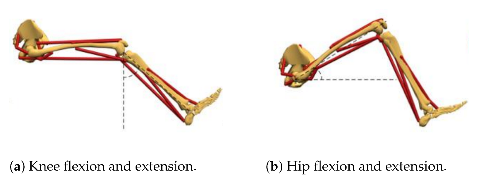
2.1. Determine the Range of Joint Motion Angle
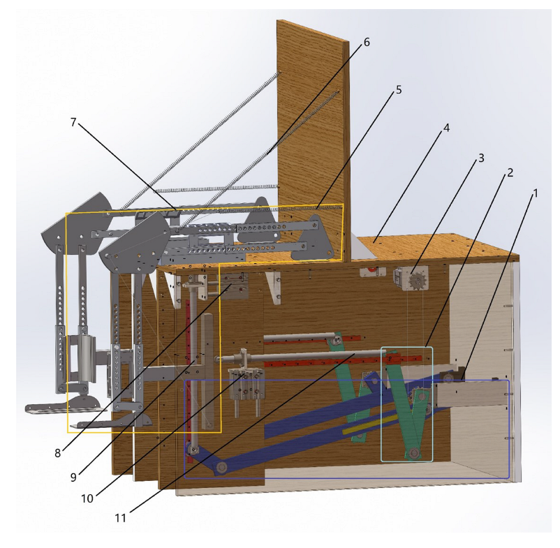
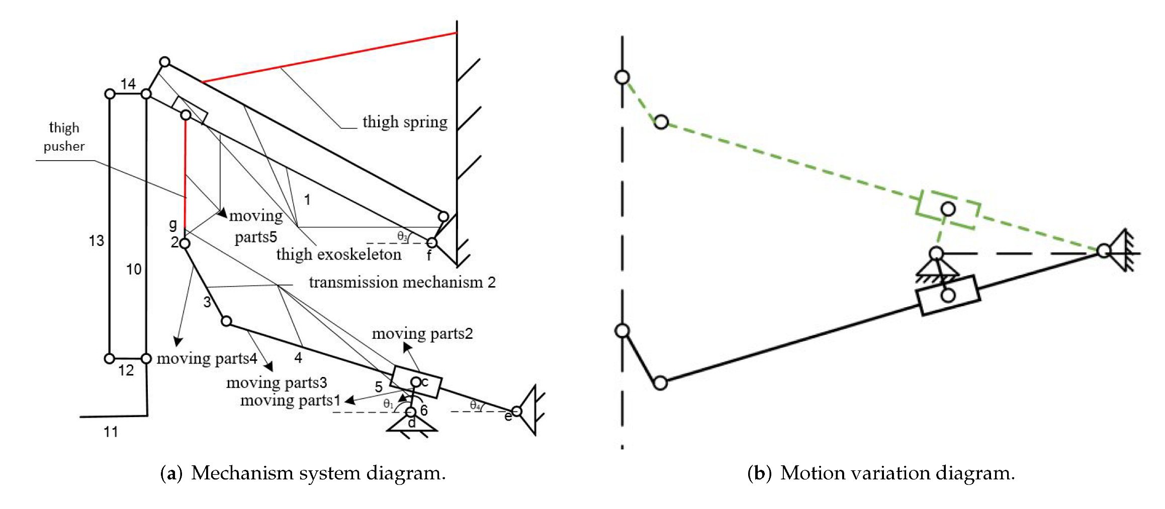
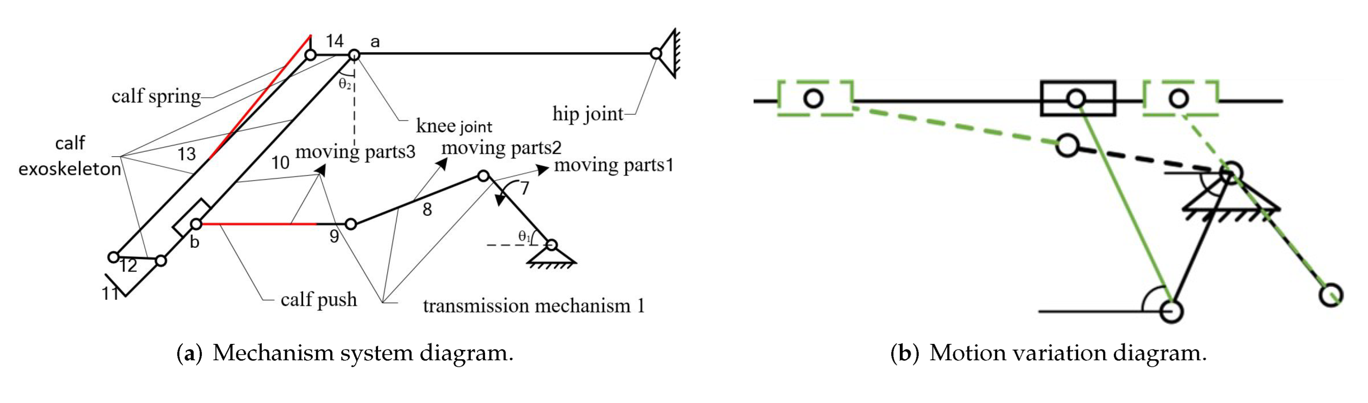
2.2. Design of Mechanism
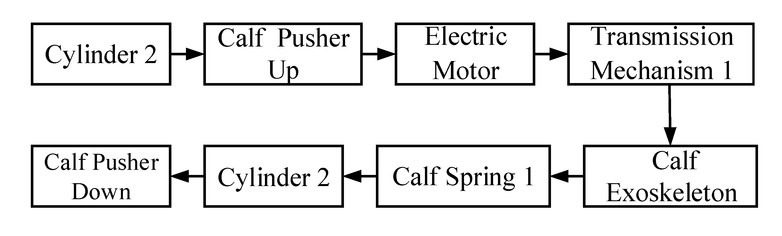
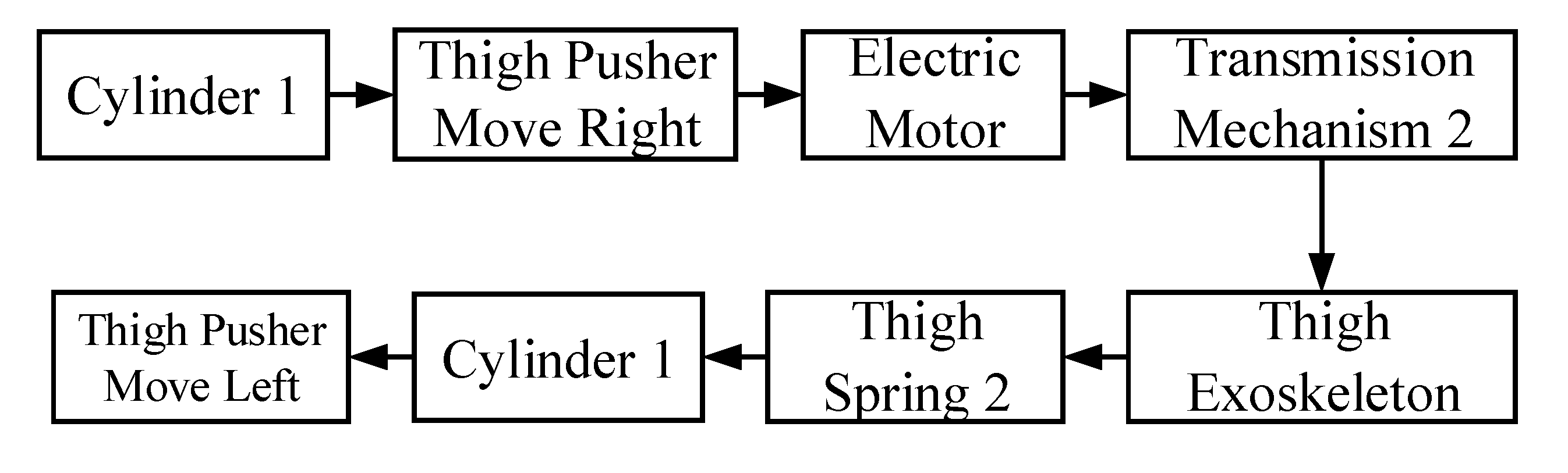
2.3. Principles of Rehabilitation Training
3. Kinematic Analysis
4. Analysis of Gravity Balance Characteristics
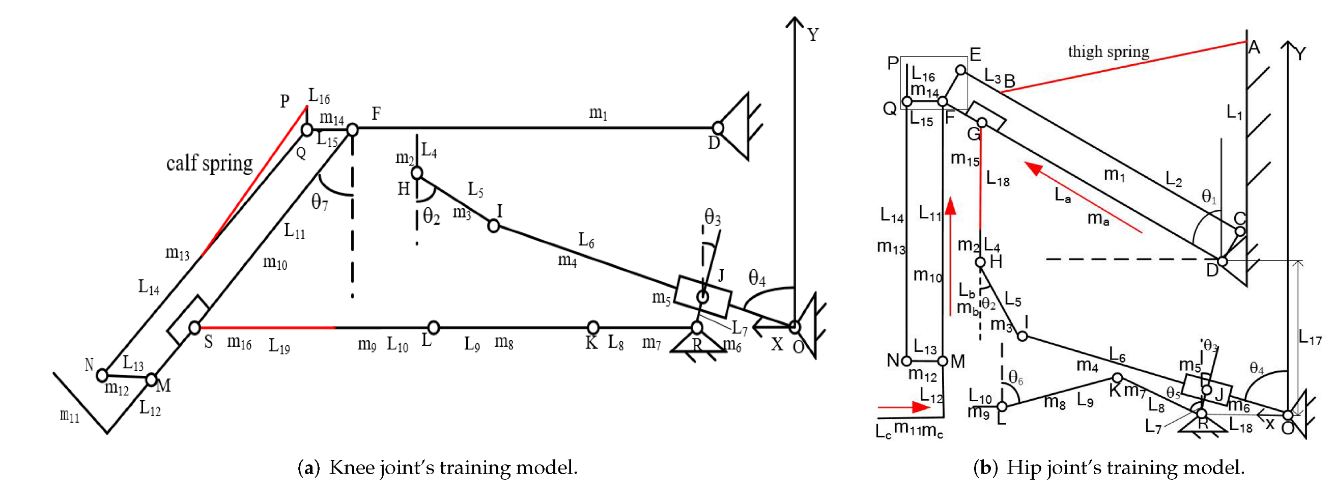
4.1. Establish the Model
4.2. Potential Energy Analysis of Knee Joint Rehabilitation Training System
4.3. Potential Energy Analysis of Hip Joint Rehabilitation Training System
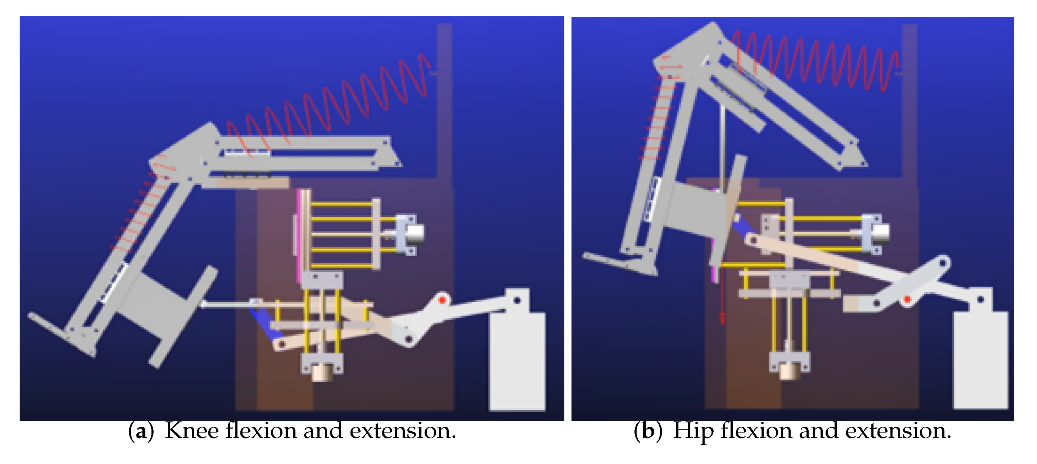
4.4. Simulation Analysis of the Rehabilitation Training Device Model
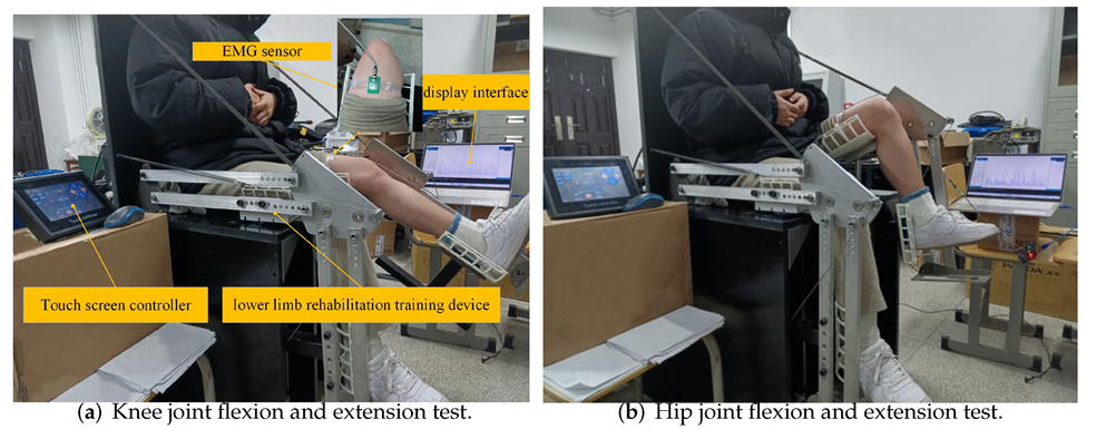
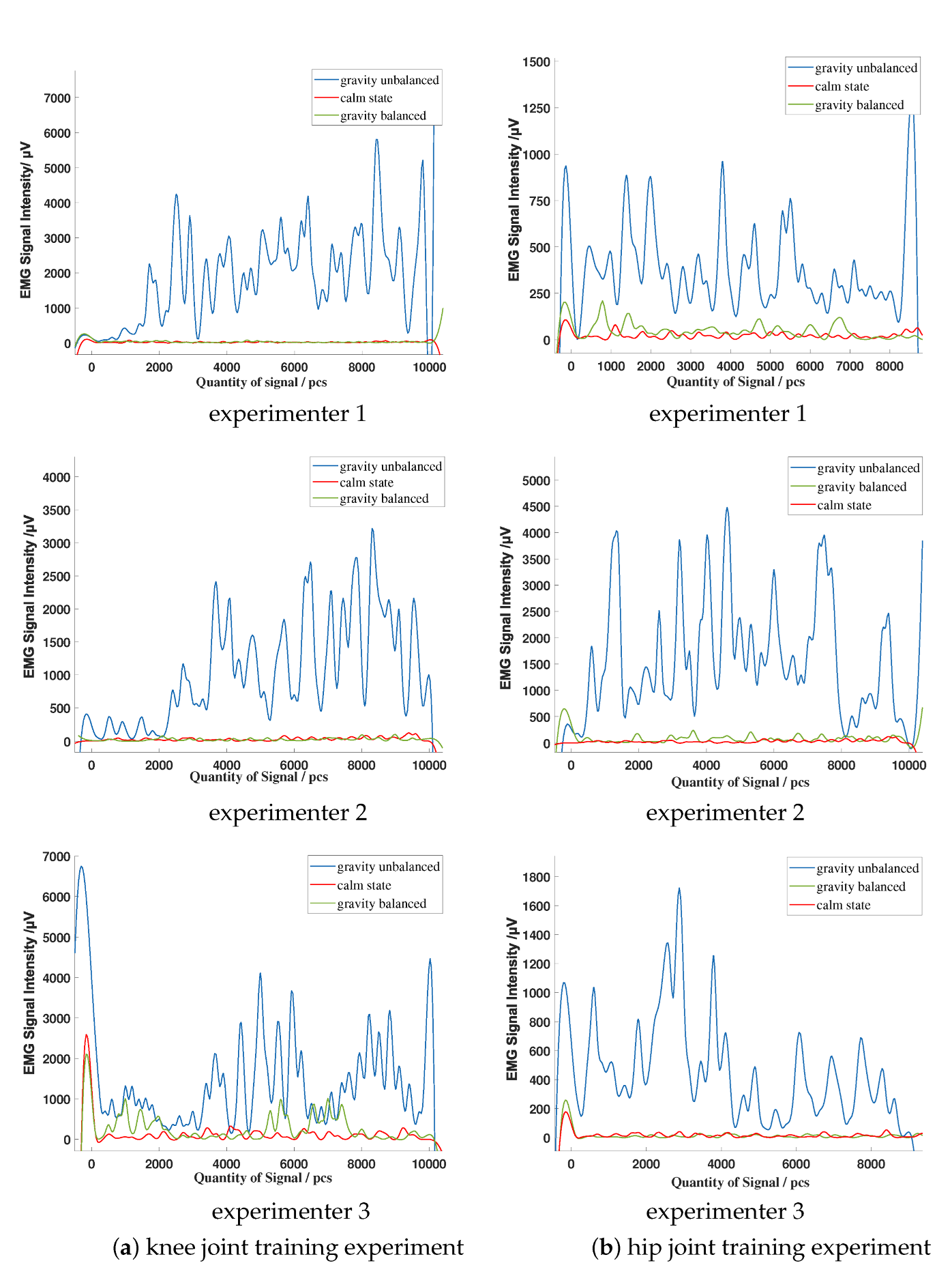
5. Experiment
6. Discussion
7. Conclusions
Author Contributions
Funding
Institutional Review Board Statement
Informed Consent Statement
Data Availability Statement
Conflicts of Interest
References
- Zhang, J.; Mu, Y.; Zhang, Y. Effects of Acupuncture and Rehabilitation Training on Limb Movement and Living Ability of Patients with Hemiplegia after Stroke. Behav. Neurol. 2022, 2022, 2032093. [Google Scholar] [CrossRef] [PubMed]
- Hwang, S.; Lee, S.; Shin, D.; Baek, I.; Ham, S.; Kim, W. Development of a Prototype Overground Pelvic Obliquity Support Robot for Rehabilitation of Hemiplegia Gait. Sensors 2022, 22, 2462. [Google Scholar] [CrossRef]
- Saranya, S.; Poonguzhali, S.; Karunakaran, S. Gaussian mixture model based clustering of Manual muscle testing grades using surface Electromyogram signals. Phys. Eng. Sci. Med. 2020, 43, 837–847. [Google Scholar] [CrossRef] [PubMed]
- Gregson, J.M.; Leathley, M.J.; Moore, A.P.; Smith, T.L.; Sharma, A.K.; Watkins, C.L. Reliability of measurements of muscle tone and muscle power in stroke patients. Age Ageing 2000, 29, 223–228. [Google Scholar] [CrossRef] [Green Version]
- Paternostro-Sluga, T.; Grim-Stieger, M.; Posch, M.; Schuhfried, O.; Vacariu, G.; Mittermaiier, C.; Bittner, C.; Fialka-Moser, V. Reliability and validity of the Medical Research Council (MRC) scale and a modified scale for testing muscle strength in patients with radial palsy. J. Rehabil. Med. 2008, 40, 665. [Google Scholar] [CrossRef] [Green Version]
- Virani, S.S.; Alonso, A.; Aparicio, H.J.; Benjamin, E.J.; Bittencourt, M.S.; Callaway, C.W.; Carson, A.P.; Chamberlain, A.M.; Cheng, S.; Delling, F.N.; et al. Heart Disease and Stroke Statistics—2021 Update: A Report From the American Heart Association. Circulation 2021, 143, 254–743. [Google Scholar] [CrossRef]
- Ullas, U.; Rajendrakumar, P.K. Design of a Low-Cost Lower Limb Rehabilitation Exoskeleton System. IOP Conf. Ser. Mater. Sci. Eng. 2021, 1132, 012008. [Google Scholar] [CrossRef]
- Pournajaf, S.; Goffredo, M.; Agosti, M.; Massucci, M.; Ferro, S.; Franceschini, M.; Italian Study Group on Implementation of Stroke Care (ISC Study). Community ambulation of stroke survivors at 6 months follow-up: An observational study on sociodemographic and sub-acute clinical indicators. Eur. J. Phys. Rehabil. Med. 2019, 55, 433–441. [Google Scholar] [CrossRef]
- Carlo, A.D.; Lamassa, M.; Franceschini, M.; Bovis, F.; Cecconi, L.; Pournajaf, S.; Paravati, S.; Biggeri, A.; Inzitari, D.; Ferro, S.; et al. Impact of acute-phase complications and interventions on 6-month survival after stroke. A prospective observational study. PLoS ONE 2018, 13, e0194786. [Google Scholar] [CrossRef] [Green Version]
- Aprilea, I.; Iacovelli, C.; Goffredo, M.; Cruciani, A.; Franceschini, M. Efficacy of end-effector Robot-Assisted Gait Training in subacute stroke patients: Clinical and gait outcomes from a pilot bi-centre study. NeuroRehabilitation 2019, 45, 1–12. [Google Scholar] [CrossRef]
- Molteni, F.; Guanziroli, E.; Goffredo, M.; Calabrò, R.; Franceschini, M. Gait Recovery with an Overground Powered Exoskeleton: A Randomized Controlled Trial on Subacute Stroke Subjects. Brain Sci. 2021, 11, 104. [Google Scholar] [CrossRef]
- Goffredo, M.; Mazzoleni, S.; Gison, A.; Infarianto, F.; Pournajaf, S.; Galafate, D.; Agosti, M.; Posteraro, F.; Franceschini, M. Kinematic parameters for tracking patient progress during upper limb robot-assisted rehabilitation: An observational study on subacute stroke subjects. Appl. Bionics Biomech. 2019, 2019, 4251089. [Google Scholar] [CrossRef] [Green Version]
- Franceschini, M.; Mazzoleni, S.; Goffredo, M.; Pournajaf, S.; Galafate, D.; Criscuolo, S.; Agosti, M.; Posteraro, F. Upper limb robot-assisted rehabilitation versus physical therapy on subacute stroke patients: A follow-up study. J. Bodyw. Mov. Ther. 2020, 24, 194–198. [Google Scholar] [CrossRef]
- Reed, J.A. Research progress in weight reduction training. Chin. J. Phys. Med. Rehabil. 2002, 24, 58–60. [Google Scholar]
- Zhao, J.; Zou, R.; Xu, X.; Hu, X. Design and Analysis of Body Weight Support Based Treadmill for Lower Limb Rehabilitation Training. Prog. Biomed. Eng. 2014, 35, 187–190. [Google Scholar]
- Jing, M.K. A dissertation submitted in partial fulfillment of the requirements for the academic degree of Master of Engineering. Master’s Thesis, Harbin Institute of Technology, Harbin, China, 2019. [Google Scholar]
- Chen, Z.P. Conceptual Study of a Passive Exoskeleton System for Reduced Gravity Locomotion Training for Astronaut. Master’s Thesis, Nanjing University of Aeronautics & Astronautics, Nanjing, China, 2014. [Google Scholar]
- Chu, Y.L.; Kuo, C.H. A Single-DoF Self-Regulated Gravity Balancer for Adjustable Payload. J. Mech. Robot. 2017, 9, 1–8. [Google Scholar] [CrossRef]
- Cheng, Z.; Foong, S.; Sun, D.; Tan, U.X. Towards a multi-DOF passive balancing mechanism for upper limbs. In Proceedings of the International Conference on Rehabilitation Robotics, Singapore, 11–14 August 2015; pp. 508–513. [Google Scholar] [CrossRef]
- Xu, W.; Chen, Z.; Fan, R.; Wen, X. Improve the Wrist Structure of the Haptic Master under Gravity Balance. Mech. Sci. Technol. Aerosp. Eng. 2017, 36, 196–201. [Google Scholar]
- Mei, Q.; Gu, Y.; Dong, S.; Li, J.; Fernandez, J. Review on the Application of Image-Based Subject-Specific OpenSim Lower Extremity Musculoskeletal Model into Biomechanics Research. J. Med. Biomech. 2019, 35, 259–264. [Google Scholar]
- Zhou, M.; Huang, Q.; Jiang, X. Progress in the application of gait analysis in orthopedic and physical rehabilitation. J. Orthop. Clin. Res. 2021, 6, 243–249. [Google Scholar]
- Xie, E.; Zhan, J. Progress in big data analysis of gait biomechanics. J. Med. Biomech. 2021, 36, 984–989. [Google Scholar]
- You, Y.; He, W.H.; Song, Q.Y. Progress in the application of different gait analysis systems in osteoarthritis. Sci. Technol. Her. 2021, 39, 35–42. [Google Scholar]
- Yulan, D. Ergonomics, 4th ed.; Beijing Institute of Technology Press: Beijing, China, 2011. [Google Scholar]
- Chao, H.; Yun, G.; Ying, C. Human joint mobility measurement system. Chin. J. Med. Phys. 2016, 33, 34–38. [Google Scholar]
- GB 10000-88; Human Dimensions of Chinese Adults. China Association for Standardization: Beijing, China, 1988.
- Karl, H.E.; Kroemer, H.J.; Kroemer, K.E. Engineering Physiology, 4th ed.; Springer: Berlin/Heidelberg, Germany, 2010. [Google Scholar]
- Gianluca, G.; Giuseppe, C. Gravity Compensation of Robotic Manipulators Using Non-linear Spring Configurations. In Proceedings of the International Conference of IFToMM ITALY, Online, 9–11 September 2020; pp. 310–317. [Google Scholar] [CrossRef]
- Tschiersky, M.; Hekman, E.; Brouwer, D.M.; Herder, J.L. Gravity Balancing Flexure Springs for an Assistive Elbow Orthosis. IEEE Trans. Med. Robot. Bionics 2019, 1, 177–188. [Google Scholar] [CrossRef] [Green Version]
- Shi, X.; Qin, P.; Zhu, J.; Zhai, M.; Shi, W. Feature Extraction and Classification of Lower Limb Motion Based on sEMG Signals. IEEE Access 2020, 8, 132882–132892. [Google Scholar] [CrossRef]
- Khoshdel, V.; Akbarzadeh, A.; Naghavi, N.; Sharifnezhad, A.; Souzanchi-Kashani, M. sEMG-based impedance control for lower-limb rehabilitation robot. Intell. Serv. Robot. 2018, 11, 97–108. [Google Scholar] [CrossRef]
- Petersen, I.L.; Nowakowska, W.; Ulrich, C.; Struijk, L.N.S.A. A Novel sEMG Triggered FES-Hybrid Robotic Lower Limb Rehabilitation System for Stroke Patients. IEEE Trans. Med Robot. Bionics 2020, 2, 631–638. [Google Scholar] [CrossRef]


| Level | Standard of Evaluate |
|---|---|
| Level 0 | No measurable or perceptible muscle contraction. |
| Level 1 | Slight muscle contraction, but cannot cause joint movement. |
| Level 2 | Able to perform full range joint movement under weight reduction state. |
| Level 3 | Able to perform full range of motion while resisting gravity, but cannot resist resistance. |
| Level 4− | Active movement against gravity and slight resistance. |
| Level 4 | Active movement against gravity and moderate resistance. |
| Level 4+ | Active movement against gravity and strong resistance. |
| Level 5 | Normal power. |
| Category | Knee Joint Angle (°) | Hip Joint Angle (°) |
|---|---|---|
| Normal range of motion | 0∼30 | 0∼30 |
| Equipment’s range | 0∼60 | 0∼40 |
| Institution | Rods | Size (mm) |
|---|---|---|
| Transmission mechanism 1 | Moving part 1 | 167 |
| Moving part 2 | 290 | |
| Component 9 | 10 | |
| Calf push rod | 520 | |
| Transmission mechanism 2 | Moving part 1 | 52 |
| Moving part 3 | 825 | |
| Moving part 4 | 100 | |
| Component 2 | 10 | |
| Thigh push rod | 520 |
| Angle | |||||||
| Value (°) | 40 | 53 | 36 | 77 | 0 | 45 | 60 |
| Rods | |||||||||||
| Length (mm) | 506 | 419 | 40 | 10 | 100 | 825 | 52 | 167 | 290 | 10 | 370 |
| Rods | |||||||||||
| Length(mm) | 60 | 70 | 370 | 70 | 44 | 458 | 213 | 520 | 270 | 270 | 10 |
| Parts | ||||||||||
| Mass (kg) | 0.256 | 0.023 | 0.044 | 0.118 | 0.011 | 0.039 | 0.078 | 0.041 | 0.023 | 0.089 |
| Parts | ||||||||||
| Mass (kg) | 0.577 | 0.009 | 0.089 | 0.239 | 0.426 | 0.426 | 8.3 | 4.5 | 1.2 |
| Limb Parts (kg) | Thin | Normal | Obese |
|---|---|---|---|
| Calf | 3 | 3.7 | 4.5 |
| Thigh | 5.1 | 6.4 | 8.3 |
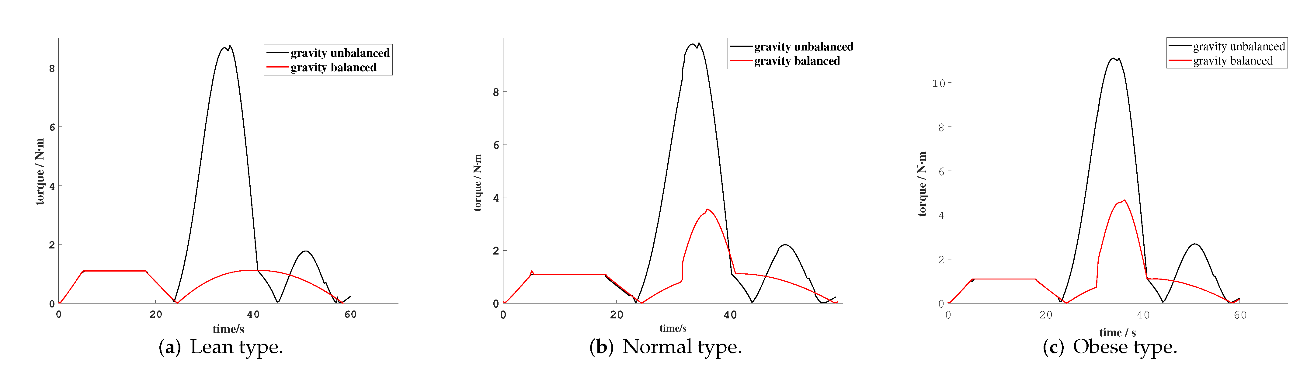
| Status of Rehabilitation Equipment | Maximum Torque of Lean Type (N·m) | Maximum Torque of Normal Type (N·m) | Maximum Torque for Obese Type (N·m) |
|---|---|---|---|
| Gravity balanced | 1.12 | 3.5 | 4.7 |
| Gravity unbalanced | 8.8 | 9.8 | 11.1 |
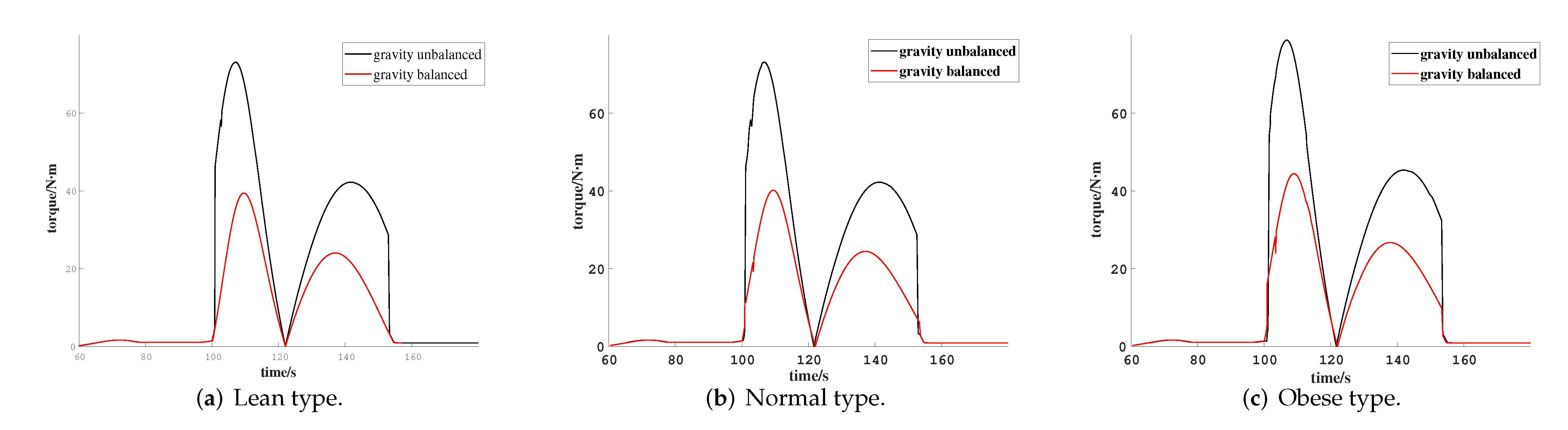
| Status of Rehabilitation Equipment | Maximum Torque of Lean Type (N·m) | Maximum Torque of Normal Type (N·m) | Maximum Torque for Obese Type (N·m) |
|---|---|---|---|
| Gravity balanced | 39.0 | 40.1 | 44.4 |
| Gravity unbalanced | 68.8 | 73.1 | 78.7 |
| Parameters | Numerical Value |
|---|---|
| Materials | Aluminum alloy 6061 |
| Drive motor | MODEL SUPSM-T-H2-130-15015-AP1B61 |
| Cylinder | J-MGPM20 × 50Z |
| Touch screen controller | QL7B-2 Dual Axis |
| Subjects | Height (cm) | Age | Body Weight (kg) |
|---|---|---|---|
| 1 | 166 | 20 | 53 |
| 2 | 172 | 25 | 70 |
| 3 | 181 | 23 | 86 |
| Subjects | During Knee Joint Rehabilitation | During Hip Joint Rehabilitation |
|---|---|---|
| Subject 1 | 97% | 75% |
| Subject 2 | 93% | 84% |
| Subject 3 | 71% | 83% |
Publisher’s Note: MDPI stays neutral with regard to jurisdictional claims in published maps and institutional affiliations. |
© 2022 by the authors. Licensee MDPI, Basel, Switzerland. This article is an open access article distributed under the terms and conditions of the Creative Commons Attribution (CC BY) license (https://creativecommons.org/licenses/by/4.0/).
Share and Cite
Wang, J.; Kan, Y.; Zhang, T.; Zhang, Z.; Xu, M. Model Analysis and Experimental Study of Lower Limb Rehabilitation Training Device Based on Gravity Balance. Machines 2022, 10, 514. https://0-doi-org.brum.beds.ac.uk/10.3390/machines10070514
Wang J, Kan Y, Zhang T, Zhang Z, Xu M. Model Analysis and Experimental Study of Lower Limb Rehabilitation Training Device Based on Gravity Balance. Machines. 2022; 10(7):514. https://0-doi-org.brum.beds.ac.uk/10.3390/machines10070514
Chicago/Turabian StyleWang, Jianping, Yanpeng Kan, Taisheng Zhang, Zhen Zhang, and Manman Xu. 2022. "Model Analysis and Experimental Study of Lower Limb Rehabilitation Training Device Based on Gravity Balance" Machines 10, no. 7: 514. https://0-doi-org.brum.beds.ac.uk/10.3390/machines10070514