1. Introduction
Historically, steam turbine units (STU) have been used at thermal power plants (TPPs). Unit capacities of STUs steadily rose, which made it possible to commission new TPPs with power units with a capacity of 300, 500, and 800 MW. A 1200 MW steam turbine prototype was installed at the Kostromskaya GRES (thermal power plant) in Russia.
The commissioning of large TPPs helped reduce specific capital costs for their construction, operating costs for their maintenance and repair, and specific fuel consumption for the production of 1 kWh of electricity and 1 Gcal of heat.
In recent decades, the new construction and modernization of TPPs have involved a wide use of gas-turbine units (GTUs) and gas-reciprocating units (GRUs), which increase fuel heat utilization factor and efficiency. For example, the efficiency (at the outlets) of modern GTUs [
1] and GRUs [
2] is about 44–45%, and the design engineering departments of leading manufacturing plants work on its further increase. Combined-cycle plants created on their basis achieve the efficiency in a range of 61–64% [
3].
Simultaneously with the construction of large TPPs, given the trend towards decentralization of generating capacities, there is massive commissioning of distributed generation (DG) 25–100 MW facilities. The power plants that occupy the leading position in implemented projects are:
The distributed generation facilities, as a rule, can provide a reliable power supply to consumers in three cases [
5,
6,
7]:
Parallel operation with the power system;
Islanded operation, which results from the automatic separation of a power system area with one or more DG facilities due to emergency events in the power system that impede the normal functioning of consumer electrical loads;
Off-grid power supply to the consumer electrical loads.
Parallel operation with the power system provides several advantages [
8]:
Supply of surplus electricity to the grid;
Fast direct starts of large electric motors;
Normal operation of electrical loads in the event of a sudden shutdown of a generating unit or a distributed generation facility.
To date, tens of thousands of successfully operating DG projects have been implemented. However, there are cases where either grave technical issues arose with gas-turbine units or there were failures of power supply to industrial consumers with subsequent significant financial losses [
9]. Experience of operation and investigations of accidents show that the main reason for these problems to occur is incorrectly considered design features of modern GTUs and GRUs in the course of modeling [
10,
11].
The development of projects for the construction of new power plants, including DG facilities, should focus on a set of tasks. Firstly, these are the tasks associated with an increase in short-circuit currents, which may require replacement of high-voltage circuit breakers, if their breaking capacity is insufficient, or the installation of current-limiting devices (isolation transformers) [
12]. Secondly, the tasks associated with the need to adjust the algorithms of operation and settings for relay protection devices and emergency control systems in the adjacent network [
13,
14].
This study focuses on the influence of design features of the gas-turbine and gas-reciprocating units on the nature and parameters of transient processes due to emergency disturbances in the adjacent network and shows how this influence should be taken into account when designing the emergency control systems.
2. Specific Features of Power Flow Calculations
Power flows should be comprehensively calculated for possible design, off-design, and emergency conditions. These calculations are particularly significant if GTU operation failures can cause considerable damage to consumers.
The calculations should factor in the features of the applied software systems [
15]:
Some software systems use a simplified description of algorithms for regulating speed control systems used for STU, which, without adaptation, is not suitable for mathematical modeling of GTU and GRU;
The primary area of software application is calculations in backbone networks, where transient processes depend little on the correctness of load models. However, in power system areas with DG facilities, this is of paramount importance.
The calculations should rely on verified models of generating units, which correctly take into account the design features of drive motors and the laws of regulation of automatic speed control and automatic excitation control. To ensure correct mathematical modeling of generating unit, it is instrumental to use graphs of a change in the rotation speed of generating units with fixed permissible load surges/drops that are obtained from the generating unit manufacturer to calculate changes in the generating unit rotation speed under actual load surges/drops.
The accuracy of the power flow calculations depends on the correctness of the used models of generating units and the applied software adequacy to the problems solved. The results of simulation modeling, in turn, depend on the correctness of base technical decisions made when designing emergency control systems.
Building a computational model and then calculating power flows, one should pay special attention to:
The accuracy of parameters of the equivalent circuit of the network and power plants (DG facilities) in the considered power system area, as well as the sections of the power system closest to the power system area;
Settings of relay protection devices in the adjacent network (accurate information on the possible duration of short-circuit in the considered power system area and the adjacent network is required) [
16];
Parameters of AC electric motors (the composition of parameters depends on characteristics of software used, technological processes, voltage, and installed capacity of electric motors (the main electric motors should be introduced into the design model individually, whereas others should be used in an aggregated manner, by equivalenting);
Statistical data on single-phase and multiphase short-circuits of various durations (being auxiliary, still they indicate the probabilities of disturbances and the emergency conditions to be caused by them);
Information about the settings of automated systems for technological control of production processes (which are necessary to check their consistency with the operation of relay protection devices of generating units to prevent unnecessary shutdowns and minimize damage from power supply disruptions).
The main difficulty in the calculations of transient processes in the power system areas with DG facilities lies in the variety of computational options that must be analyzed, namely [
17,
18,
19]:
The initial scheme of the power system area and its repair versions (as a rule, there are many of them), including islanded operation of the power system area;
The available generation in the power system area, given its current scheme;
Specific features of generating units at power plants (parameters of excitation systems and automatic excitation regulators; laws of regulation of the automatic speed control, considering delays in gaining power; settings and time delays of relay protection devices);
The loads and variations in their composition, if these variations are significant (from maximum to minimum with their different locations within the power system area network);
The sites of normative and non-normative disturbances, given statistical data;
Specific features of relay protection operation in the power system area network (the most important thing is the maximum duration of multiphase short-circuits);
Other characteristics of the power system area, which, among other things, may appear in the future scheme.
If the calculated transient processes end unsuccessfully: some of the electrical equipment is turned off and remains shutdown, some electric motors stall and are disconnected by relay protection devices and others, then it is necessary to envisage effective emergency response measures, from the perspective of their economic feasibility:
Install emergency control systems, whose algorithms of operation and settings should be harmonized with those of the process relay protection devices;
Increase the installed capacity of generating units at power plants (DG facilities);
Install electric energy storage devices and others.
When making a list of emergency response measures, one should bear in mind that the calculations usually do not embrace the entire transient process (from the initial disturbance to the return to the normal conditions) but only its initial phase, which identifies electrical equipment whose operation can be disturbed, which in the end determines the characteristics of the emergency conditions.
The calculated scheme of a large power system area, as a rule, does not include all electrical equipment but only that whose parameters affect calculation results. When performing the power flow calculations, one should seek to:
Decrease their number by excluding simple cases, for which it is sufficient to understand the nature of the transient process (for example, operation of relay protection devices of generating units at close short-circuits);
Reduce the number of logical and design options by pre-grouping the types of calculations by class (for example, by types of normative and non-normative disturbances) to enable the analysis of results and conclusions on whether or not the emergency response measures were effective.
Let us consider an example of grouping the computational problems by initial disturbance for a power system area with a DG facility in islanded operation:
Normal start-up of a large electric motor (to form a list of emergency measures, we should analyze their direct starts, which have a significant impact on operating conditions of electric loads);
Switching of power supply to groups of electric motors under no-current condition (due to process or electrical factors but not related to short-circuits in the power system area network), if such switching can take place;
Short-circuit conditions in the network under corresponding no-current conditions during the operation of automatic load transfer, automatic reclosing, and others, with the determination of the possibility and admissibility of self-start of electric motors (or automatic restarting by steps with voltage control).
Short-circuit should be taken into account both in the network of the power system area and in all networks connected to it, especially those of lower voltage classes, where overcurrent protection with time selectivity is used as the main or backup protection.
3. Fundamental Design Features of Gas-Turbine Units
Design features of gas-turbine units (GTUs) affect significantly the nature and parameters of transient processes when emergency disturbances occur in the adjacent network.
Single-shaft GTUs are heavier and have a constant rotation speed equal to that of a synchronous generator. To ensure high reliability and thermal efficiency; and reduce capital and operating costs, they are designed according to the elementary cycle. Such GTUs have a heavy rigid shaft, slide bearings, and constant blade airfoils along most of the flow path length, excluding the first compressor stages and the last gas turbine stages. Single-shaft GTUs impose higher requirements on the quality of construction work and infrastructure, and their service life is comparable to that of a STU.
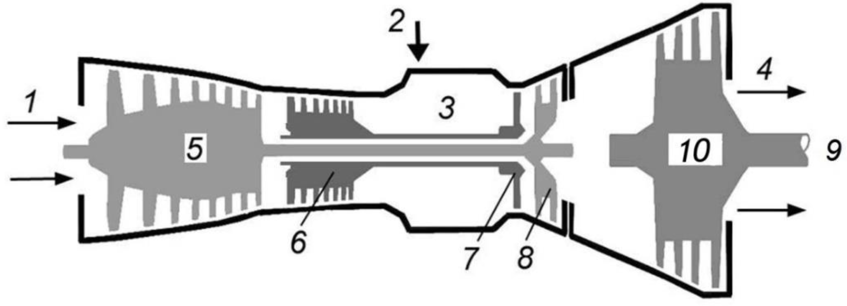
Two-shaft and three-shaft GTUs, i.e., GTUs with a free power turbine (FPT), have properties that are unfavorable in terms of the dynamic stability of generators.
Figure 1 shows a sketch of a three-shaft GTU with FPT.
The reason why the dynamic stability margin in gas turbines with FPT decreases is explained by the fact that in contrast to single-shaft gas turbines (where the compressor, turbine, and generator are on the same shaft) they have relatively small moments of inertia. The total value of the mechanical constant of inertia of all masses rotating on the same shaft with the generator is about 3–4 times less for the GTU with FPT than for a single-shaft GTU and 2–3 times less than for STU.
The advantages of GTUs with FPT are that they provide higher power output, have a lower specific weight and dimensions, and are distinguished by the ease of replacing the entire gas-turbine engine or its individual elements to perform high-quality repairs at the factory. They have a higher throttle response, which allows their use in peak conditions. They are also easy to maintain and repair and have lower infrastructure requirements, although a smaller resource either. Shafts of GTUs with FPT have a variable number of revolutions in a range of 6–14 thousand rpm [
20].
With large generation shedding and increase in generator speed, the speed control system sharply reduces fuel supply to the combustion chamber, but the compressor, which has a large moment of inertia, continues to supply air to the FPT. As a result, the rotation speed of FPT and generator can increase so much as to trigger the process protection designed to disconnect the gas turbine. A considerable load shedding is likely with a close multiphase short-circuit in the adjacent network, the duration of which depends on the response time of the relay protection devices that localize it. Moreover, GTU may fail during no-current conditions of the automatic reclosers on a power transmission line.
Load shedding is also possible at synchronous oscillations in the power system when a power plant is switching to islanded operation with surplus power, and during islanded operation with a significant decrease in power demand [
21].
With large load dumps, gas supply to GTU sharply decreases to reduce the power and avoid an unacceptable increase in the rotation speed. With the gas supply reduced, if the flame in the combustion chamber (cooled by the airflow from the compressor) goes out, the GTU will be unable to stabilize the rotation speed and shut down by process protection devices. With thermally stressed states in the GTU gas-air duct, abrupt load sheds lead to accelerated depletion of its resource [
22].
If, after the torch goes out, gas continues to enter the GTU combustion chamber, then flammable and toxic gases can be emitted into the atmosphere, and there can be an explosion in the GTU due to ignition of fuel when it comes into contact with parts of the hot section.
According to various manufacturing plants, the lower limit of an operating power range (the process minimum load) for different gas-turbine units is 40–60% of
Pnom. For comparison, the process minimum of most types of steam turbine units is 15–20% [
23].
The efforts of the design engineering departments of the GTU manufacturers focus on mitigating the indicated flaw, i.e., decreasing the mass and moment of inertia of the compressors and increasing the mass and moment of inertia of the free power turbine. An alternative to this solution is to discharge a significant part of the air supplied by compressors to the GTU combustion chamber into the atmosphere.
At present, a decrease in the dynamic stability margins of GTUs with FPT does not lead to an overall decline in the power system’s dynamic stability because their number is insignificant. However, with the massive use of GTUs with FPT and GRUs, the value of the equivalent inertia constant of the power system will gradually go down, which will increase the rate of transient processes. These circumstances will require a revision of technical requirements towards a rise in the speed of high-voltage circuit breakers, relay protection devices, and emergency control systems.
Out-of-step conditions occur relatively often in networks with GTUs with FPT, and therefore, their specific features should be taken into account when identifying settings of the out-of-step protection system. Of great significance are three particularities if the out-of-step condition is admissible for GTU in terms of mechanical strength:
1. When synchronism is lost, generators reach large slips, but the sufficiently fast operation of the speed control system of GTUs increases the likelihood of spontaneous restoration of their synchronization. According to the theory of transient processes of synchronous machines, wide variations in the slip of generators due to the small values of the mechanical constant of inertia make it easier to restore synchronization. However, due to a large frequency difference, the out-of-step conditions can last for several seconds (5–10 turns or more).
Out-of-step conditions cause significant mechanical stresses in all structural elements of the GTU, including bearings and foundations. Therefore, protracted out-of-step conditions (several turns) may be unacceptable in terms of their mechanical strength. It is worth noting that STUs tend to withstand long out-of-step conditions without destruction. Therefore, out-of-step protection devices have two main elements: an angular element, which measures the difference angle between voltages at the ends of the controlled section, in which crank is used as a sign of out-of-step conditions, and an element to control the number of cranks, after which control action is generated to eliminate out-of-step conditions [
24].
Most of the modern gas-turbine units manufactured in various countries do not principally allow out-of-step conditions due to the mechanical strength requirements and must be disconnected from the network before the first crank occurs. The out-of-step operation of such gas-turbine units is eliminated by relay protection devices with an angle setting of up to 180° to prevent the GTU transition to out-of-step conditions. Consequently, the admissibility and duration of out-of-step conditions, along with the choice of out-of-step protection algorithms for specific gas turbines, should be taken into account in the design of emergency control systems [
25].
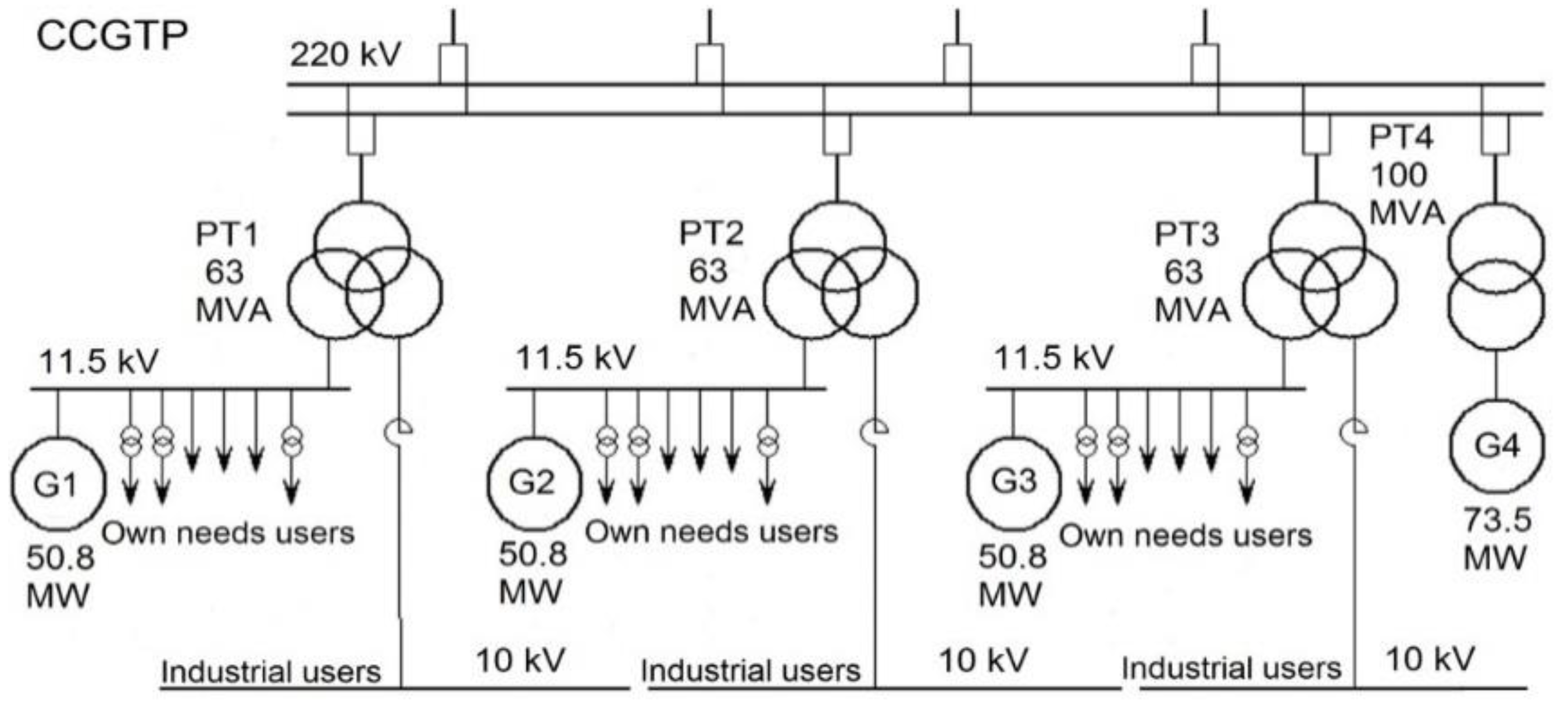
Let us consider an example of a combined-cycle gas turbine plant (CCGTP) (3 GTUs × 50.8 MW + STU × 73.5 MW) connected to a 220 kV network.
Figure 2 shows a simplified single-line schematic circuit diagram of the CCGTP.
Calculations of transients are performed in the software package MUSTANG.
Transient processes were calculated using a computational scheme of a real power system. The calculations employed verified models of generating plants provided by the manufacturers of gas-turbine and gas-reciprocating units. The complete Park-Gorev equations were used in the calculations to factor in electromagnetic transient processes in the rotors and stators of electric machines [
26,
27,
28]
where
are flux linkages in coordinates
d,
q, and 0, respectively;
is an angle between the axis of pole d and axis A in the system of coordinates
d,
q for electric machine;
and
are transverse and longitudinal currents of stator;
s is the Laplace operator.
In Equation (1), the flux linkages equal:
where
and
are inductance and inductive reactance of zero sequence,
is field current,
is mutual inductive reactance of the field winding and stator winding in the longitudinal axis,
is inductive reactance of the stator winding in the longitudinal axis,
is inductive reactance of the stator winding in the transverse axis,
M is mutual inductance.
When the rotor rotates, the angle γ changes continuously:
where
is the synchronous angular velocity; Δ
ω is the angular velocity of the rotor relative to the synchronously rotating axis.
Before the calculation of dynamic stability, we determined the initial pre-emergency condition of the power system and checked if it was balanced.
For proper modeling of transient processes, the computational scheme reflected all the power plants, at which the processes could affect the results that are significant for solving the set calculation problem. Given that it is generally unacceptable to replace dynamic characteristics of the motor load of major electrical consumers with static ones in the calculation of transient processes in networks with industrial consumers, the dynamic models of this load were used to build the calculation model. All induction motors connected to 10 and 11.5 kV buses (
Figure 2) were represented by individual dynamic characteristics, which made it possible to achieve the highest accuracy in the calculations.
The motor load considerably affects the calculations of transient processes due to two circumstances:
Small values of mutual resistances between generating units of DG facilities and motor load;
The total value of the motor load is comparable with the total rated power of generating units of the DG facility, which is why the nature of transient processes is mainly determined by load properties.
Electric loads in different sections, separated by transformers or current-limiting reactors, are affected with varying degrees of intensity. Therefore, the processes of dynamic stability loss, rundowns, and self-starting of electric motors for different groups of electrical loads run differently and have various effects on generating units of the DG facility. These specific features were taken into account in equivalenting, which is allowed when the electrical loads have close parameters.
The steps of equivalenting with the view to obtaining a generalized dynamic model of induction motors were as follows:
Replace a group of induction motors connected to the same bus section with one induction motor with a total rated active power and weighted average (according to Pnom.i) values of rated torques, maximum and starting currents, tgφnom, as well as resistance torques of driven mechanisms;
Replace one induction motor connected to the buses through some resistance with an induction motor connected to the same buses.
For modeling purposes, static electrical loads, including lighting, heating plants, air conditioners, ovens, and others, were combined into a small number of devices and represented by their static characteristics of the load active power depending on voltage Pst(U).
The calculation of transient processes with the MUSTANG software relies on the methods of numerical integration of nonlinear equations defining the dynamic properties of the power system, given the algorithms for the functioning of automatic speed regulators and automatic excitation regulators of generating units, as well as the action of emergency control systems.
The accuracy of the calculated transient processes is limited mainly by the accuracy of input information. The calculation error rises when the number of oscillatory cycles of checked coordinates (angles between the EMF of synchronous generators) in the calculated transient process increases, especially if the calculation reveals an out-of-step condition in the power system.
It is important to note that the calculations of transient conditions in power systems are almost always approximate for many reasons:
A decrease in the number of electrical machines and devices taken into account by calculation model of the power system (which is not so much due to the capabilities of the calculation of large schemes, but due to the labor costs of the preparation of all the initial data);
Approximation of mathematical models of components;
Inaccuracy in setting the initial parameters;
Methodological, random, and computational errors.
As a rule, the correctness of results obtained in the standard and proven calculations of transient processes does not cast any doubt since the total errors do not exceed 5–10% [
29].
4. Transient Simulation Results of Gas-Turbine Units
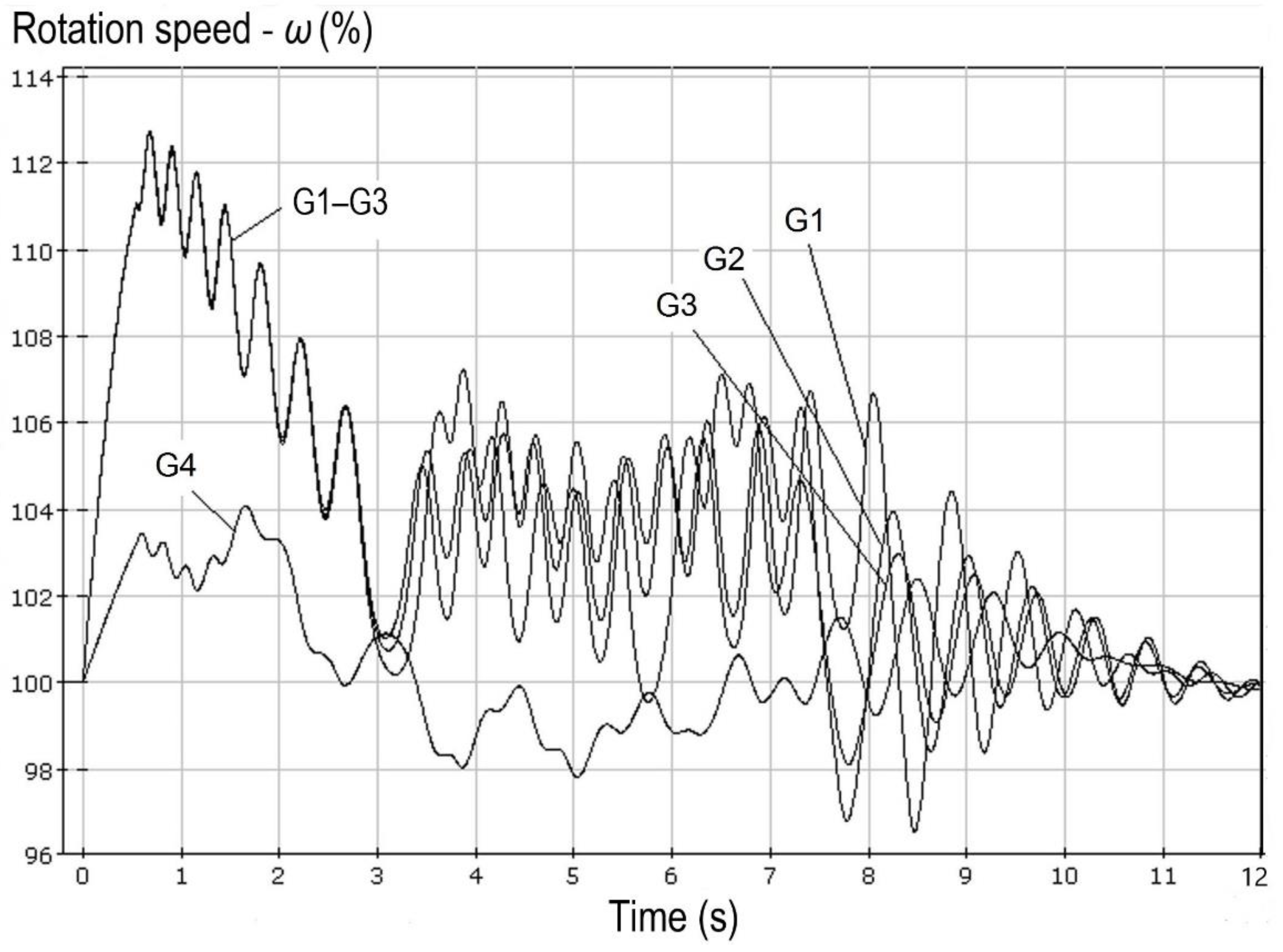
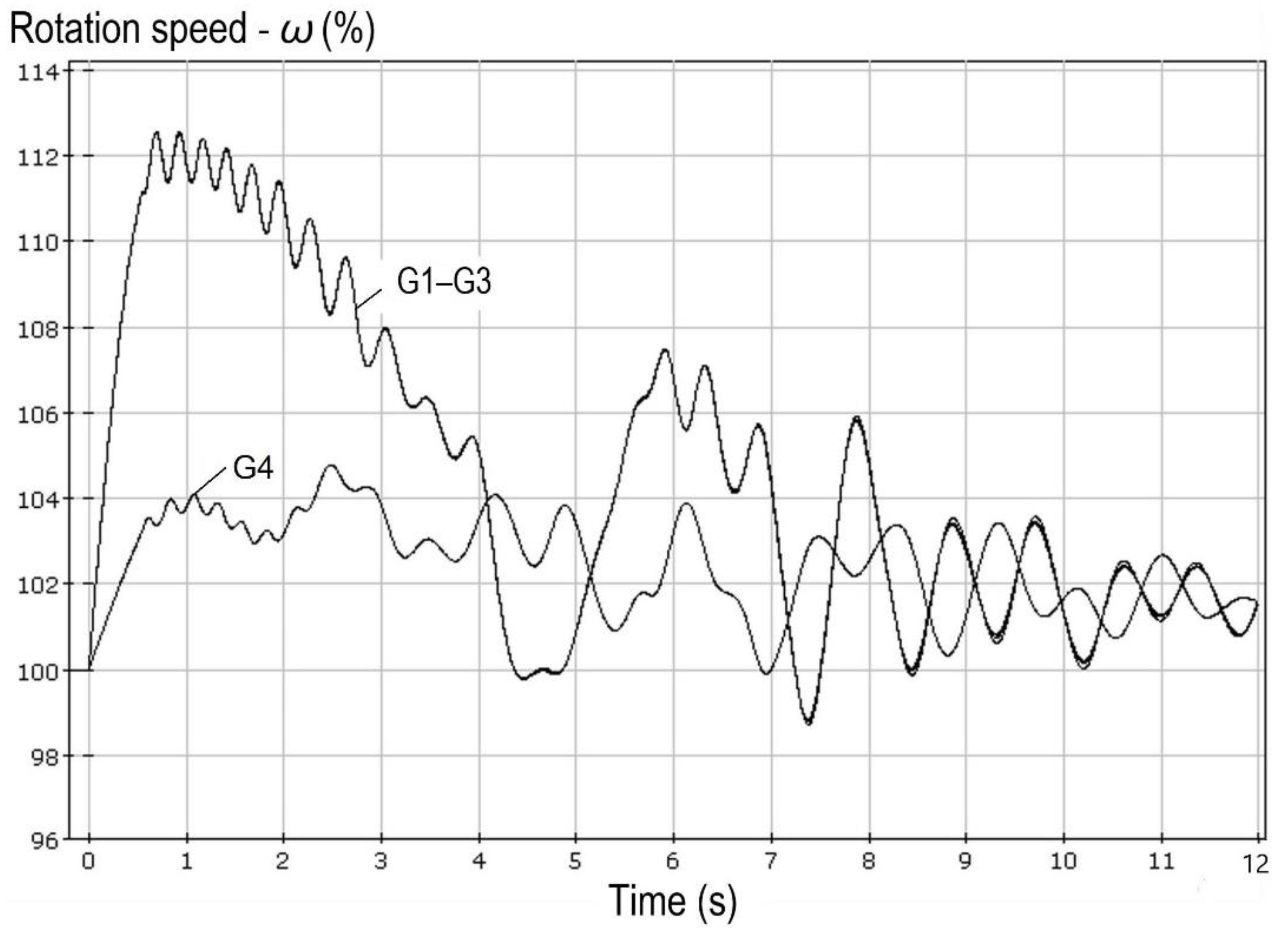
Figure 3 demonstrates the results of calculating the transient process at a close three-phase short-circuit with disconnection of one of the 220 kV transmission lines connecting the CCGTP with the power system (the automatic recloser is switched off according to the operating conditions). The initial network scheme is under repair (one 220 kV power transmission line is disconnected near the CCGTP).
As a result of a three-phase short-circuit, all generators of the CCGTP switch to the out-of-step operation, the attempt to synchronize them with one another and with the power system (at t ≈ 3 s) fails, and the out-of-step condition continues. After that, the out-of-step condition (G1–G3 have the highest frequency, the frequency of G4 is intermediate between the frequency of G1–G3 and the frequency in the network), at a reduced network voltage, transitions to a multi-machine one. At t ≈ 8.5 s, the synchronization of the CCGTP generators is restored.
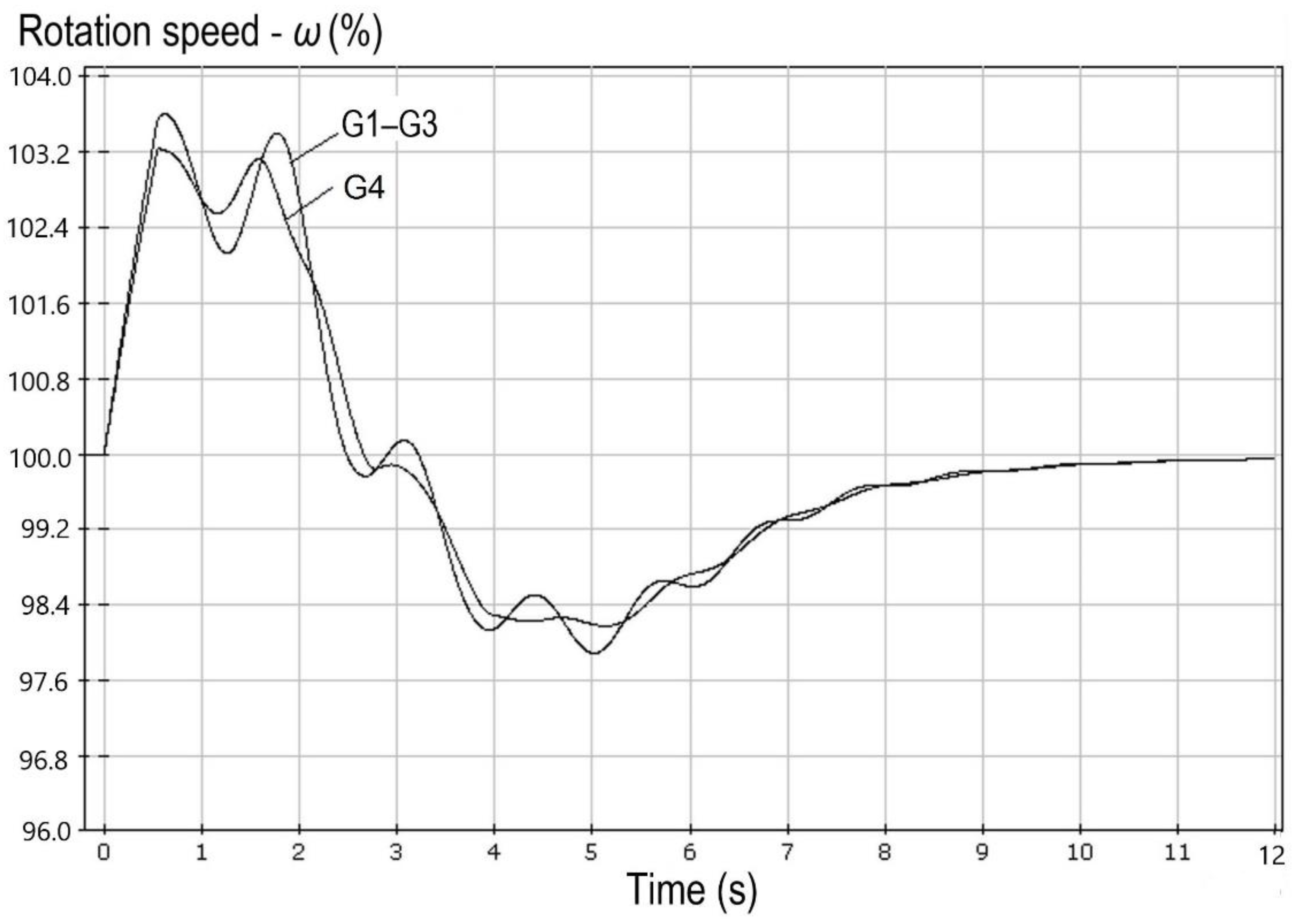
In the same scheme and operating conditions, but with single-shaft gas turbines instead of two-shaft ones, synchronism would recover fast, as shown in
Figure 4.
2. Out-of-step conditions in the distribution networks cause considerable voltage drops at consumer substations and, therefore, affect much the operation of electric loads, i.e., primarily, electric motors. The stalling of many electric motors leads to additional voltage drops and significantly complicates the restoration of synchronization. The influence of load parameters on the considered transient process is shown in
Figure 5 and
Figure 6.
All parameters of the initial calculated scheme, power flow, and disturbance are similar to those in
Figure 3, but load composition at the network nodes located near the CCGTP varies: in the option in
Figure 3, the power consumption of induction motors is 40% of the total load, in
Figure 5—20%, and in
Figure 6—80%, which is typical of industrial facilities.
For the case shown in
Figure 5, the out-of-step condition lasts less than 2 s, while synchronization is restored after four cranks. In the transient process in
Figure 6, synchronization is not restored due to voltage avalanche in the network.
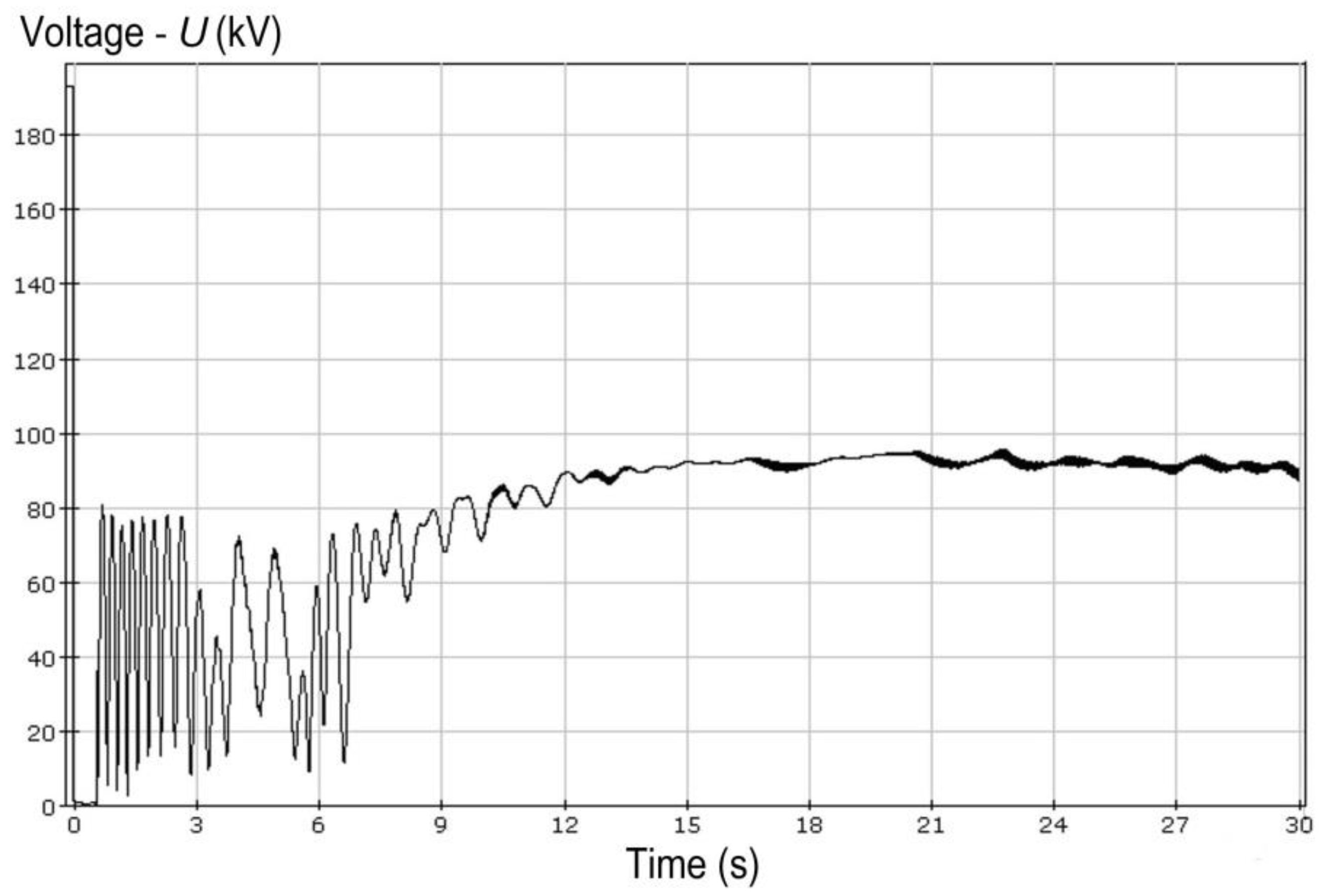
The result shown in
Figure 6 is caused by a large number of induction motors, which contribute to the creation of conditions where voltage drops below 0.5
Unom (
Figure 7) and remains low until most of the load at the network nodes is disconnected.
3. The probability that the CCGTP out-of-step condition will switch to a multi-machine one is high due to a significant difference between mechanical constants of inertia of GTUs (G1–G3) and STU (G4). It is noteworthy that multi-machine out-of-step conditions most often arise at industrial load nodes having a large proportion of synchronous motors. These conditions occur when the total power of synchronous motors is approximately equal to the overall power of generating plants at one node or adjacent nodes. Multi-machine out-of-step conditions are characterized by large displacements of the electric center of swings, which complicates their identification and elimination.
Designing the emergency control systems, one should bear in mind the high probability of out-of-step conditions at power plants based on GTUs with FPT in the case of multiphase short-circuits and spontaneous restoration of their synchronization. Consequently, rapid elimination of the out-of-step conditions will lead to unnecessary shutdowns of GTUs, which can provoke an overload of the electrical network equipment and contribute to further development of the accident.
It is advisable to provide a two-stage operation of an out-of-step protection system if it is admissible and justified by the calculations of transient processes:
On the other hand, it is crucial to prevent the transition of the out-of-step condition to a multi-machine one and not to allow it to cause secondary stability disturbances in generators at the nearest power plants and electric motors at adjacent load nodes.
With large load surges, permissible decrease in the rotation speed for single-shaft GTUs, and their operation with a low air flowrate (low electrical load) are limited by possible compressor surge or spontaneous flameout in the combustion chamber. In both cases, GTU is switched off by process protection devices without time delay.
Compressor surge is a form of unstable GTU operation and is an aerodynamic phenomenon of self-oscillation of moving air mass inside the compressor from the inlet and back. With a surge in the compressor, its efficiency decreases sharply, the GTU power fluctuates, the vibration and dynamic stresses in the rotor blades increase, and there is a risk of GTU destruction.
The flame extinction in the combustion chamber can be associated with both process factors (fuel pressure decline before the burners and other malfunctions) and changes in operating conditions of the generator.
Significant load surges in the islanded operation cause a sharp decrease in the rotation speed of the generator and power turbine of GTU with FPT, which are rigidly interconnected, given small values of the mechanical constants of inertia. In turn, a sharp drop in the rotation speed of the power turbine during the GTU operation leads to a gas-dynamic impulse directed to the flow path and elements of the gas turbine, the rotation speed of which is maximum and practically does not change since the gas turbine and the power turbine have separate shafts. In this case, the disks and rotor blades of the last stages of the gas turbine are exposed to significant mechanical stresses under the influence of a sharp pressure increase in the gas turbine gas-air path.
According to the experience of gas turbine operation, there are cases where gas turbine blades are destructed without the possibility of their recovery under out-of-step reclosing on power line under repair.
Sound technical decisions on emergency control systems can only be based on multivariate calculations of transient processes. However, one should remember that operating parameters largely depend on load parameters at the node at issue and similar parameters at the nodes of the adjacent network [
30,
31,
32].
5. Principal Design Particularities of Gas-Reciprocating Units
Gas-reciprocating units include gas-reciprocating engines (GRE), which are internal combustion engines.
Normal operation of GRE requires as much air as high is the power the engine develops. Air is supplied to the GRE through a compressor and an intercooler. The compressor is rotated by its turbine. The working fluid, which ensures the compressor turbine rotation, is the exhaust gases of the GRE. This system is called a turbocharging system. With an increase in the generator load, the speed control system, in response to a decrease in the rotation speed of the output shaft, increases fuel supply, the GRE power goes up, and the volume of exhaust gases rises either. In this case, the compressor rotation speed provides the necessary increase in air supply to the GRE.
An important fact is that the moment of inertia of the system ‘compressor turbine—compressor’ prevents rapid changes in the amount of turbocharging, as a result of which the GRE reaches higher power conditions with a delay in terms of the electrical load surge. The turbocharging delay during load shedding is not dangerous, while during load surge it leads to local overheating of GRE due to a lack of air in the piston group.
The turbocharging effect causes a significant difference between the GRE responses to generator load dumps and surges. The turbocharging delay can lead to the GRU shutdown by process protection devices when the power rises within the limits of the available one, in contrast to what occurs in the case of STU and GTU. Moreover, an increase in the rate of transient processes in the islanded power system areas with GRUs is associated with small values of mechanical constants of their inertia.
These circumstances lead to significant deviations in operating parameters during emergency disturbances in the power system area network, including load surges and sheds related to switching on/off the consumer electrical equipment.
The consequences of switching the power system area to islanded operation, where generating units cannot meet the entire load, are determined by a combination of two factors: active power shortage leading to a frequency decrease and reactive power shortage causing voltage decline.
6. Transient Simulation Results of Gas-Reciprocating Units
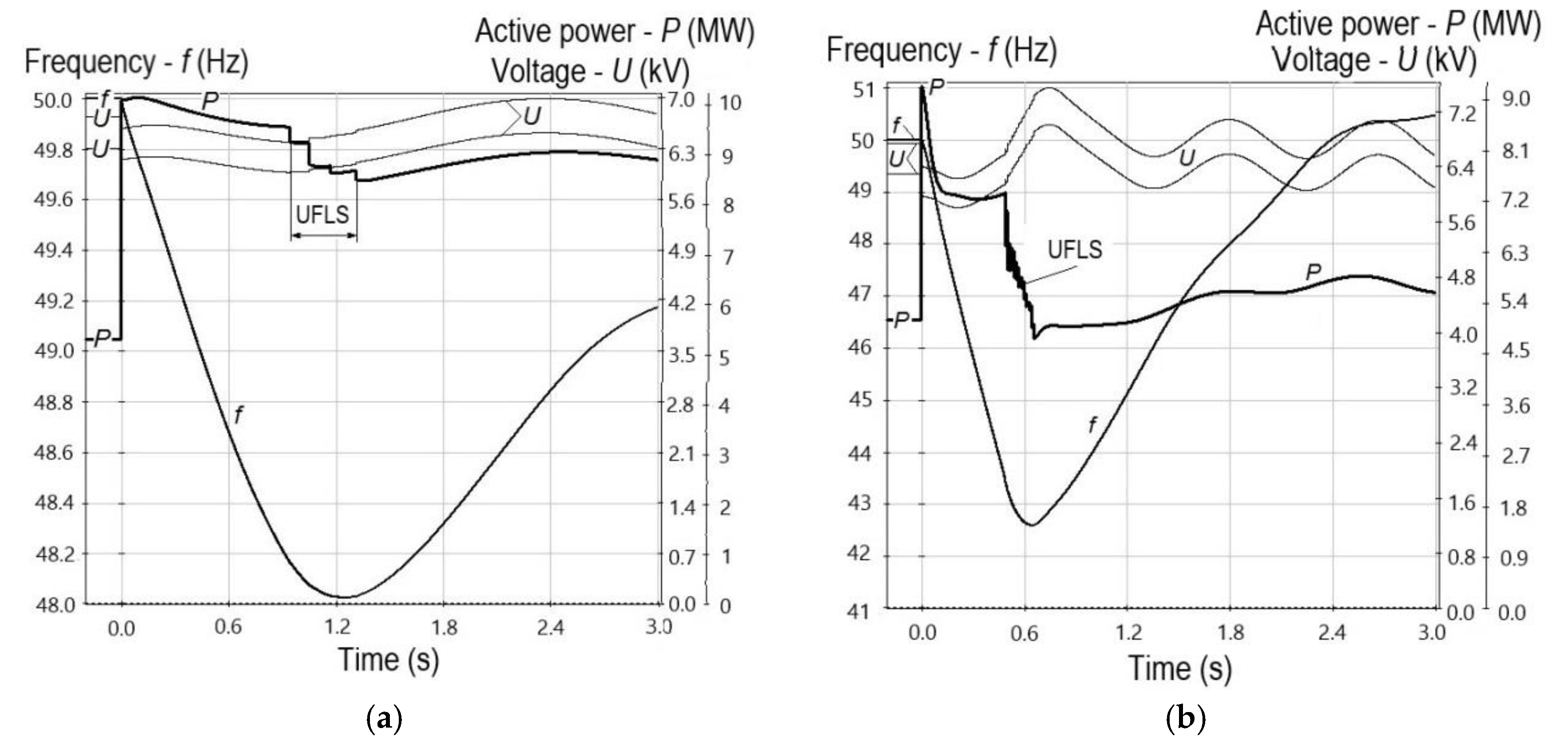
The effect of these factors can be evaluated by comparing the results of calculations of transient processes in one calculated scheme, as shown in
Figure 8, under the same initial active power shortage of 50%, but with different generating units.
Figure 8a shows the transient process in the case of using 6 MW STUs in the power system area, and
Figure 8b indicates the case of using 2 MW GRUs.
As seen from
Figure 8a, frequency in the power system area is
fmin = 48.0 Hz, however, the automatic under-frequency load shedding (UFLS) occurs (4 stages, 1.5 MW, which is 17% of
Pload = 9 MW). In
Figure 8b, frequency in the power system area deviates significantly,
fmin = 42.5 Hz, the automatic under-frequency load shedding system operates (16 stages, 5.4 MW, which is 60% of
Pload). In the latter case, the frequency decline rate increases by ≈6 times, which is why GRUs can be disconnected by the relay protection or process protection devices [
33].
When replacing automatic under-frequency load shedding in the transient process (
Figure 8b) with additional load shedding (operates when 3 GRUs are turned off with a response time of 0.1 s), we obtain that the disconnection of 52% of
Pload causes a frequency deviation
fmin = 47.8 Hz. In this case, the magnitude of load shedding will correspond to the initial active power shortage, GRUs will remain in operation, and power supply to consumers will not fail.
GRU has one significant feature—with a short-term decrease in the rotation speed below the minimum permissible value, pressure in cylinders, which is necessary to ignite the working mixture in the compression phase, is not provided. As a result, GRU is switched off without time delay by the process protection device.
To prevent the negative impact of load surges on GRU, manufacturing plants introduce a ban on instantaneous load surges, the values of which depend on the initial load of GRU. The interval between power surges is limited and is, as a rule, 1–2 min. The prevention of dangerous dynamic conditions during load surges involves the use of:
Reduction in the voltage at the generator terminals is an effective measure to decrease the dynamic frequency drops in the case of electrical load surges on the GRU in islanded operation, provided the magnitude of active power load depends significantly on voltage.
This technical solution may not give a positive effect if the magnitude of the load depends little on voltage, which is typical of load nodes, at which most of the active power is consumed by electric motors. When the GRU load rises due to the automatic load transfer under no-current condition, the voltage drop may prove unacceptable and even provoke a voltage avalanche.
A reliable judgment on how instrumental is the special generator excitation current control under various schemes and operating conditions can be made based on the calculations of transient processes. We should keep in mind that synchronous motors being part of the load can completely change a picture of transient processes, especially if the excitation of synchronous motors is voltage controlled.
If the voltage drops considerably and quickly, load shedding is significant, and active power balance in the power system area can be restored, which will lead to the restoration of the nominal frequency. Typical automatic under-frequency load shedding devices are not adapted to this scenario of the accident development. Moreover, frequency avalanche can be so fast that the automatic under-frequency load shedding (time delay is 0.3–0.4 s) cannot prevent it. The use of an additional load shedding (ALS) scheme instead of automatic under-frequency load shedding can limit the voltage drop in the power system area, which ensures a quick self-start of all electric motors, thus proving the ALS effectiveness. In this case, however, the amplitude of frequency oscillations increases, although the GRU operation time with reduced frequency declines.
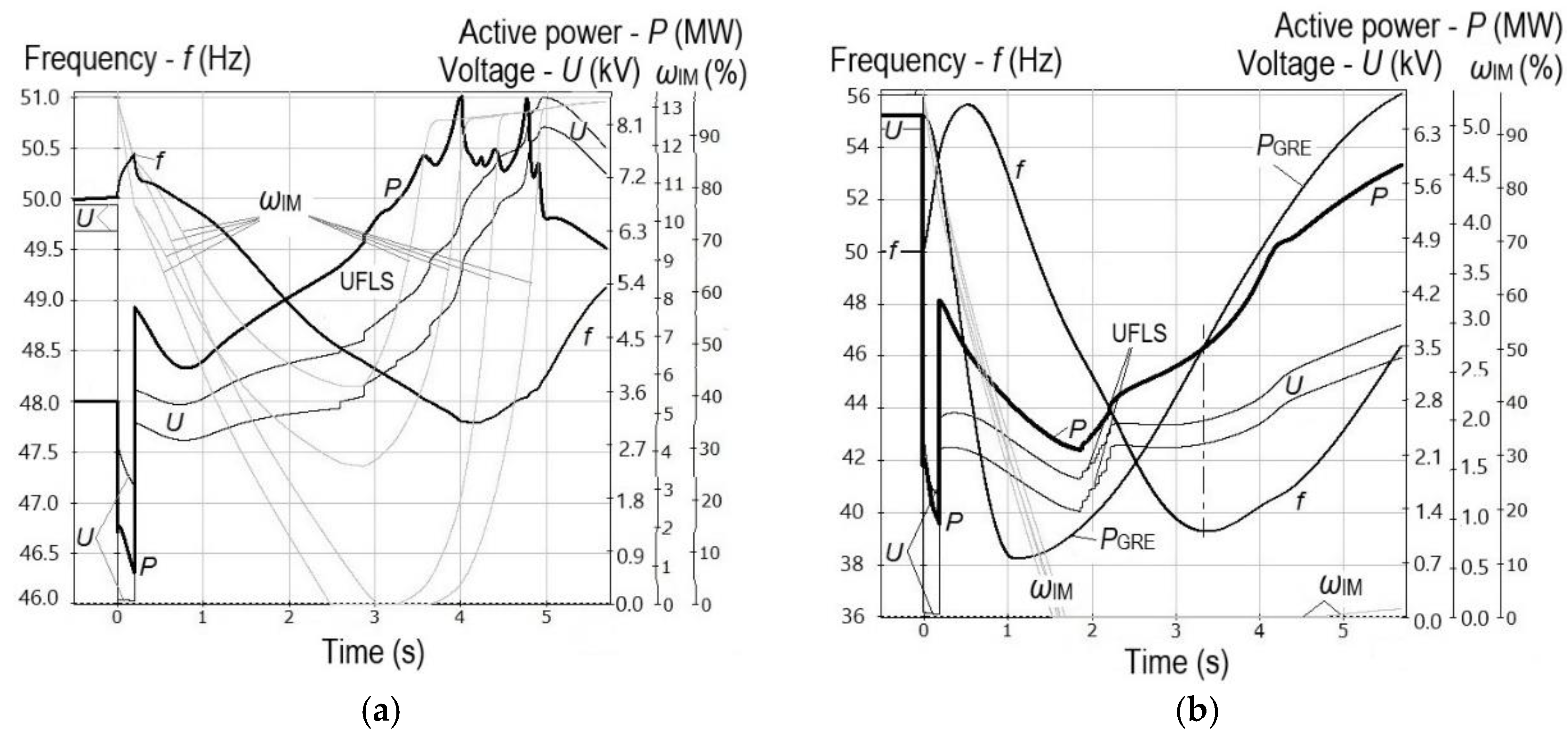
The generating unit disconnection as a consequence of a short-circuit, at which the voltage in an islanded power system area drops sharply, alters the transient process nature.
Let us consider transient processes when one of two 6 MW STUs (
Figure 9a) and three of six 2 MW GRUs (
Figure 9b) are disconnected following a three-phase short-circuit, 0.2 s long, in the network.
After the short-circuit clearance, voltage in the power system area with STUs (
Figure 9a) is ≈40% of
Unom, electric motors are braked (the graph selectively shows the rotation speed ω
IM for four induction motors). When the voltage rises (the generator excitation boosting conditions) and the automatic under-frequency load shedding is triggered, self-starts of the induction motors begin, the ends of self-starts of each group of induction motors correspond to the peaks of the active power of the generators (at
t ≈ 4 and 5 s).
In the transient process in the power system area with GRUs (
Figure 9b), the frequency deviations are much larger. Given the design specific characteristics, GRUs are decelerated faster, the voltage drops more considerably (at a constant excitation current of generating units under the excitation boosting conditions; the GRU EMF is proportional to rotation speed). At a voltage of <40% of
Unom, all electric motors stop, but after unloading by the automatic under-frequency load shedding, as the power PGRE and voltage increase, the rotation speeds of some induction motors go up, but so slowly that the probability is high that these induction motors and GRUs will shut down.
Consequently, the design of the connection of GRU-based power plants (DG facilities) should involve comprehensive calculations of power flows to identify the potential risks of generators’ disconnections due to emergency disturbances and possible surges and dumps of the load.
7. Conclusions
Nowadays, power plants, including DG facilities, widely use gas-turbine and gas- reciprocating units, which fundamentally differ in their design from steam turbine units. This fact has a significant impact on the nature and parameters of transient processes in the case of emergency disturbances, especially those to occur in islanded operation.
The calculations of power flows should rely on verified models of GTUs and GRUs, which would correctly take into account the design features of drive motors of the generating units, and the laws of regulation of automatic speed controllers and automatic excitation controllers.
A significant feature of single-shaft GTUs and GRUs is that they cannot operate when a short-term but significant drop in frequency occurs. These conditions arise in the case of emergency shortages of active power due to the weakened connection between the power plant and the power system under repair or islanded operating conditions.
The experience of calculating transient processes of GTU with FPT and GRU shows that in the case of emergency disturbances of nominal duration, they switch to out-of-step conditions, which is due to small values of mechanical constants of inertia. The probability that such generating units will spontaneously restore synchronization is high, however, it is important to prevent the out-of-step condition from transitioning to a multi-machine one, and not to allow it to cause secondary disturbances in the stability of generators at nearby power plants and electric motors at adjacent load nodes.
The three most significant features of asynchronous modes of generating plants of distributed generation during their operation in distribution networks are identified, and recommendations are formulated for choosing out-of-step protection algorithms in the design process.
Calculations have shown that the characteristics of asynchronous modes largely depend both on the load parameters in the analyzed network node, and on similar parameters in adjacent nodes. These circumstances must be taken into account when simulating transient processes and developing design solutions for technological connection of distributed generation facilities.
The speed of automatic under-frequency load shedding is insufficient in the power system areas with GRU-based DG facilities when the active power shortages are large. The replacement of the automatic under-frequency load shedding with an additional load shedding scheme makes it possible to limit the voltage drop and ensure a quick self-start of all electric motors.
Appropriate consideration of fundamental distinguishing design features of generating units contributes to making informed technical decisions on equipping power plants (DG facilities) and the adjacent network with efficient emergency control systems.


