
Design and Thermal Stability Analysis of Swing Micro-Mirror Structure for Gravitational Wave Observatory in Space


1
Nanjing Institute of Astronomical Optics & Technology, National Astronomical Observatories, Chinese Academy of Sciences, Nanjing 210042, China
2
CAS Key Laboratory of Astronomical Optics & Technology, Nanjing Institute of Astronomical Optics & Technology, Nanjing 210042, China
3
School of Astronomy and Space Science, University of Chinese Academy of Sciences, Beijing 100049, China
*
Author to whom correspondence should be addressed.
Machines 2021, 9(5), 104; https://0-doi-org.brum.beds.ac.uk/10.3390/machines9050104
Submission received: 18 April 2021
/
Revised: 10 May 2021
/
Accepted: 15 May 2021
/
Published: 18 May 2021
(This article belongs to the Special Issue Precision Measurement and Machines)
Abstract
:A kind of swing micro-mirror structure with high stability for gravitational wave observatory in space is proposed in this paper. As the key interface instrument in the gravitational wave observatory, the swing micro-mirror structure plays a very important role. Firstly, the 3D model of the mechanism is designed and established. Then, the solution method of the index of stability, pointing jitter, is researched. After that, the thermal stability and the first-order natural frequency of the mechanism are researched via finite element analysis. The first-order natural frequency of the mechanism is 247.55 Hz, which can meet the requirements of the design. It can be seen from the results of the simulation, the amplitude spectral density of the mirror angle deviation is 3.975 nrad/√Hz when the range of temperature variation is 0.1 °C, which is able to meet the requirements of the design. The thermal stability has a closed relationship with the structural stability around the X-axis. In addition, this article also studies the thermal stability of the mechanism in the case of temperature changes in different directions. It is found that the thermal stability of the mechanism around the Y-axis would be significantly affected by the temperature changes along the Y-axis.
1. Introduction
In 1916, Albert Einstein formulated his famous theory of general relativity, based on which he predicted the existence of gravitational waves [1]. According to the different frequencies of the gravitational waves, various technologies should be used to detect the gravitational waves at different positions. Gravitational waves with frequencies greater than 10 Hz are suitable for detection on the ground. When the frequency is between 0.1 MHz and 1 Hz, it is necessary to use a gravitational wave observatory to detect the gravitational waves in space, so as to minimize the interference of noise on the ground and obtain a higher detection sensitivity.
With the rapid development of science and technology, more and more scientists focus their attention on the design and research of gravitational wave detectors. On the ground, the most famous gravitational wave detector is the LIGO gravitational wave observatory, which was built by the United States in 1984. In 2015, scientists used LIGO to detect gravitational wave signals of two black holes merging for the first time [2]. There are also other gravitational wave detectors in operation on the ground, including the GEO600 gravitational wave observatory in Hanover, Germany, and the VIRGO gravitational wave detector in Pisa, Italy. In addition, the European Space Agency is building a gravitational wave detector, eLISA, to detect low-frequency gravitational waves in space [3]. Any path length changes measured by eLISA’s interferometer arms can be attributed to the effect of gravitational waves, which proves the detection of gravitational waves [4]. EADS Astrium proposed a kind of alternative payload architecture for eLISA and proved that it was feasible to use payload architecture with only one active proof mass per spacecraft [5].
The swing micro-mirror structure is the interface of the space gravitational wave telescope and laser interferometer. It is able to transmit the light precisely to the laser interferometer after the laser enters the telescope. Gravitational waves are so weak that they would easily be masked by noise [6]. Moreover, since the distance between the transmitting instrument and receiving instrument is on the order of several million kilometers, any change of the ambient temperature in space will have a significant impact on the results of the measurements. Therefore, the instruments used to detect gravitational waves need to be extremely stable. Researchers from the TNO Opto-mechatronics Department, Netherlands, have designed an In-field Pointer Mechanism for eLISA gravitational wave detector. They tested the pointing jitter of the mechanism while the actuator was in motion but did not test its thermal stability [4,7].
In this paper, a kind of swing micro-mirror structure with high stability is proposed, which is able to meet the requirement of low-frequency gravitational wave detection in space. Then, its thermal stability is analyzed. Through 3D modeling and finite element analysis, the structural design of the swing micro-mirror structure and the thermal stability under the condition of space thermal radiation are studied.
2. Materials and Methods
2.1. Design Process of Swing Micro-Mirror Structure
The thermal stability of the swing micro-mirror structure for gravitational wave observatory in space is studied in this paper. Firstly, the mechanical structure of the mechanism is designed and parameterized, and the parametric model is obtained. Then, the index of stability is analyzed. Specifically, it can be divided into three parts: research on the fitting algorithm of mirror shape [8], research on the integrated algorithm of mirror angle deviation [9], and research on the solving method of amplitude spectral density (ASD) of mirror angle deviation. After that, the thermal stability and modal analysis of the swing micro-mirror structure are carried out. Finally, the obtained data are processed to obtain the amplitude spectral density (ASD) of the mirror angle deviation of the mechanism to evaluate its thermal stability [7].
The design of the swing micro-mirror structure is to realize gravitational wave detection in space. So, its pointing jitter and first-order natural frequency have to meet the design requirements [10]. In addition, the cost for launch is directly proportional to the weight of the mechanism, so it is necessary to carry out a lightweight design of the mechanism [11].
Design requirements:
- Pointing jitter is better than 10 nrad/√Hz;
- The first-order natural frequency is greater than 80 Hz.
2.2. Structure Design of the Swing Micro-Mirror Structure
2.2.1. Mechanical Structure Design of the Mechanism
Due to the effect of mechanical vibration, space thermal radiation, and other disturbances in space, the relative position of each part of the swing micro-mirror structure will change slightly, and the outgoing light angles will change accordingly [4]. Therefore, it is necessary that the mechanism can automatically correct the reflection angle of the mirror to meet the requirement of light transfer. In addition, the signals of space gravitational waves are very weak and easy to be covered by external interference, for which the mechanism needs to maintain very high stability. It will take a huge cost to launch the mechanism into space, and the launch cost is proportional to its weight. So, the lightweight design of the mechanism will be helpful to reduce the cost.
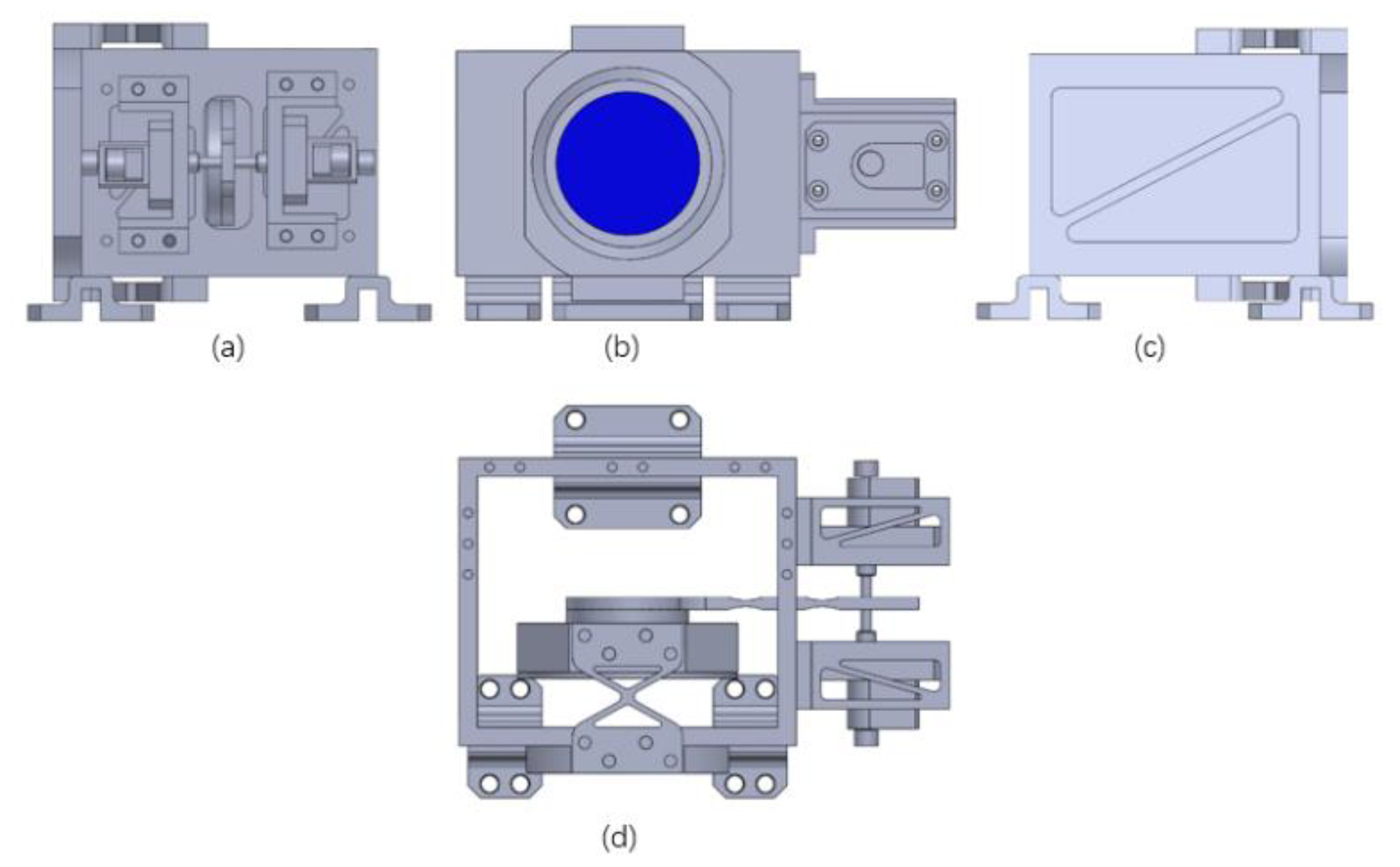
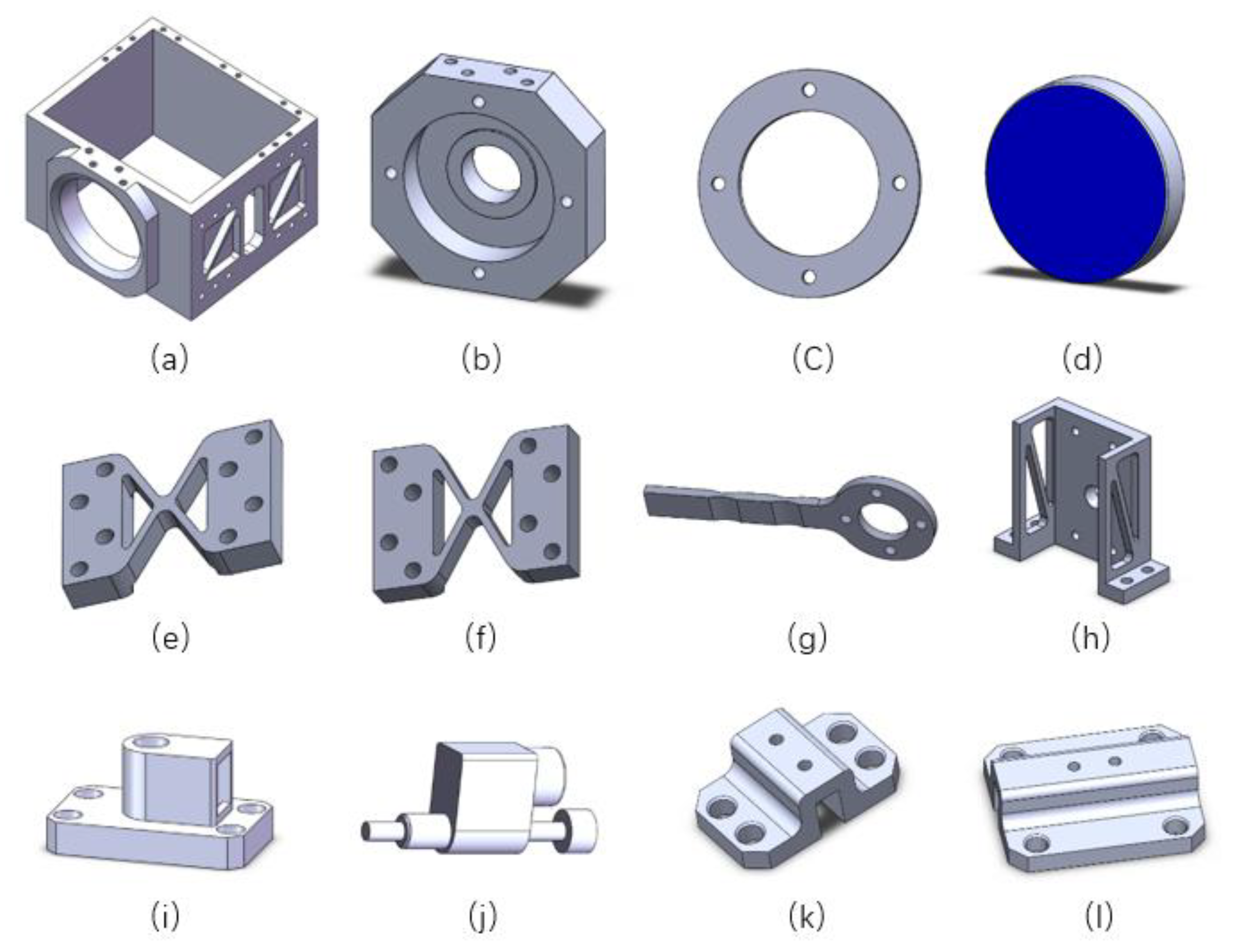
According to the mirror’s diameter of 2 inches, the initial model of the swing micro-mirror structure is established. The mechanism needs to realize swing adjustment, for which two flexible hinges and a flexible arm are designed [12]. Two displacement actuators are selected as the power source to ensure the accuracy and stability of the movement. The framework of the mechanism is designed as an integral frame structure to improve the stiffness so that the mechanism is able to bear the huge impact load during launch. The 3D models of the assembly and parts of the swing micro-mirror structure are shown in Figure 1 and Figure 2.
When the swing micro-mirror structure starts to work, the two actuators at the right end move in the same direction, which causes the flexible arm to move forward or backward. Led by the flexible arm, the mirror cell installed with the mirror will rotate to adjust the reflection angle of the mirror. The position of the mirror should be maintained after the adjustment of the reflection angle. In the case of external interference, the mechanism should be able to ensure its stability to stabilize the optical path. As shown in Figure 2, this is a kind of monolithic elastic cross hinge. Two hollowed-out triangles in flexure hinges add stability and strength to the structure. The flexible hinges are bolted to the mirror cell and the framework. The framework is hollowed out to reduce weight. Between the hollow parts, ribs are designed to enhance the strength to meet the dynamic stiffness requirement of launch. The actuator connecting plates can be completely hollowed out with only ribs remained to maintain their strength for the reason that they are not the main force-bearing part. Instruments used in space should follow the three-point support principle, so three supporting feet are designed in this mechanism, which can be divided into two kinds. The length of supporting foot A in front is shorter and the length of supporting foot B in the back is longer. This is due to the fact that there is only one supporting foot behind, which requires a longer length to spread out the huge impact load of launch. Each supporting foot has filleted corners at the edge of its vertical portion to reduce stress concentration.
2.2.2. Material Selection of the Mechanism
Due to the requirements of sufficient strength and extremely high stability, these two factors need to be taken into account in the material selection of each part. In addition, since the mechanism is to be used in space, materials with less density should be chosen as far as possible. The materials of each part are shown in Table 1.
As for the framework, it is the main part that bears the impact load and has a significant influence on the thermal stability of the whole mechanism. So, Invar is chosen as the material of the framework [13]. Similarly, it is necessary to select Invar which has a very low coefficient of thermal expansion for the supporting feet and the mirror cell for the reason that they also have a great influence on the thermal stability of the mechanism. The mirror is the most important component, which needs to choose Zerodur with excellent thermal stability and high yield strength as its material. Due to the requirement of a rotating motion and the need to withstand the huge impact force during launch, Ti6Al4V is chosen as the material of flexible hinges. For other parts, Titanium Alloy with high yield strength and low density is selected as their material. The properties of different materials are shown in Table 2.
2.2.3. Lightweight Design of the Mechanism
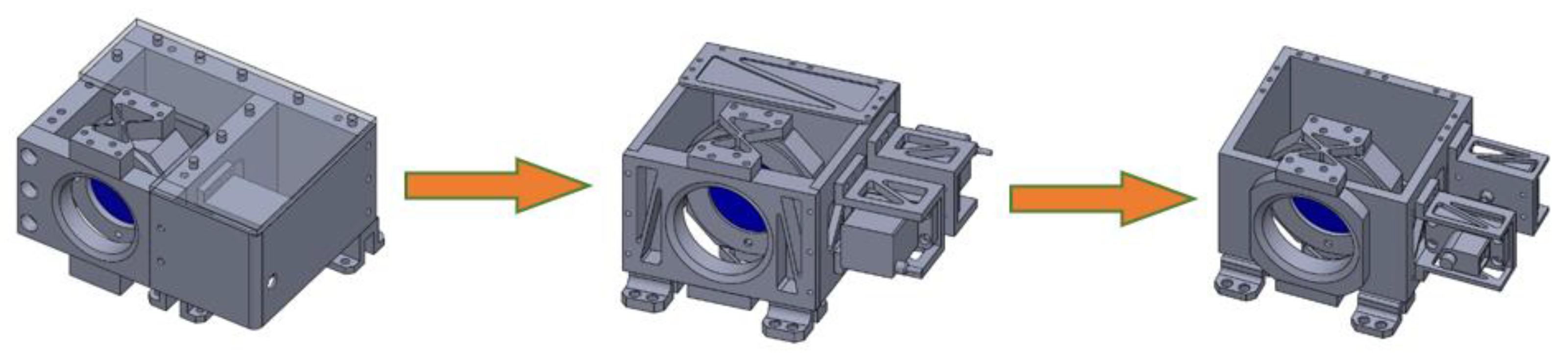
In order to reduce the launch cost, the weight of the swing micro-mirror structure must be reduced as much as possible under the premise of meeting all the requirements [14]. There are several ways to reduce the total weight of the mechanism: (1) reduce unnecessary parts or reduce the size of parts; (2) hollow out the components to remove the weight of part of the volume; (3) choose lighter materials. Figure 3 presents the initial model and the final model of the mechanism.
Through comparison, it can be found that the total weight of the mechanism is reduced from 6.33 kg to 2.05 kg by removing unnecessary parts. The reduction rate of weight is 67.6%. The size of the model has been reduced to save space. Detailed data are shown in Table 3.
2.3. The Index of Stability Analysis of the Swing Micro-Mirror Structure
2.3.1. Research on Fitting Algorithm of Mirror Shape
Let the coordinate of node in the mirror be , which is transformed to via the coordinate transformation matrix . The displacements along the X-axis, Y-axis, and Z-axis are , , and , and the rotation around the X-axis, Y-axis, and Z-axis are , , and , then
Let
If the fitting-error of the result is to be minimized, should be minimized. It can be gained through the least square method:
Based on this, the displacement of the rigid body is able to get: .
Therefore, the coordinate transformation matrix could be gained. Separate the rigid body displacement and get the coordinate of the node before the deformation which contains only the rigid body displacement:
The surface shape data of the mirror containing only surface distortion is the difference between the nodal surface shape data and the data containing only rigid body displacement. It is:
Then, the PV and RSM of the mirror can be calculated:
where PV is the peak-to-valley value and RMS is the root mean square.
2.3.2. Research on Integrated Algorithm of Mirror Angle Deviation
Finite element analysis is used to solve the deformation of each node of the mechanism after excitation. The data is used to solve the rigid body displacement of the mirror via the least square method. Then, the angle deviation of light passing through the mechanism can be calculated.
In the global coordinate system, a total of rays have been traced. The optical path of each ray is calculated as follows:
Ray 1:
Ray i:
where , and are the coordinate of ray on the primary mirror, , and are the coordinate of ray on the secondary mirror, , and are the coordinate of ray on the third mirror, , and are the coordinate of ray on the fourth mirror.
The optical path of each ray with external interference is calculated as follows:
Ray 1:
Ray :
The angle deviation of rays after passing through the swing micro-mirror structure can be calculated with the point drift of each ray and the position deviation of the theoretical point.
2.3.3. Research on the Solving Method of ASD of Mirror Angle Deviation
The mirror angle deviation of the swing micro-mirror structure in the time domain can be obtained via the method above. Since the index of pointing jitter value is 10 nrad/√Hz is in the frequency domain, it is necessary to convert the value of angle deviation in the time domain into amplitude spectral density in the frequency domain. Then, it could be evaluated and analyzed. The solving principle of amplitude spectral density is as follows [15] (pp. 68–69).
If
the following formula can be gained according to the convolution theorem.
Let , , can get:
Since is a real function, then:
The formula above is Parseval Theorem, which indicates that the total energy in the time domain is equal to the total energy in the frequency domain. The average power of the signal over the entire time axis can be calculated as follows:
Thus, the relationship between the power spectral density function and the spectral density function can be written as:
is a bilateral power spectral density function. In practice, it is often converted to unilateral power spectral density function .
The amplitude spectral density function is obtained by taking the square root of unilateral power spectral density function :
3. Finite Element Analysis of the Swing Micro-Mirror Structure
3.1. Modal Analysis
3.1.1. Theory of Modal Analysis
Modal analysis is a numerical analysis method to calculate the natural vibration characteristics of structures. The natural vibration characteristics of structures include three parts: natural frequency, damping ratio, and mode of vibration. Modal analysis is the basis of dynamic analysis. Dynamic analysis such as response spectrum analysis, random vibration analysis, and harmonious response analysis are all based on it. Modal analysis is helpful to avoid resonance phenomenon and protect the mechanism. In this paper, the swing micro-mirror structure requires a first-order natural frequency greater than 80 Hz.
In the undamped system, the vibration equation of the structure is [16] (pp. 207–208):
where is the mass matrix, is the acceleration vector of nodes, is the stiffness matrix, and is the displacement vector of nodes.
For linear systems, the free vibration equation is:
where is the eigenvector of the mode of vibration of the order, is the natural frequency of the order, and is the time.
The following equation is obtained from the above two equations.
Then,
So, the natural frequency is able to be gained through the above equation.
3.1.2. Results of Modal Analysis
The parameterized model of the swing micro-mirror structure is transformed into a finite element model. After that, the 1st to 6th natural frequencies of the mechanism can be achieved through the finite element analysis method, as shown in Table 4.
It can be seen from Table 4 that the first-order natural frequency of the mechanism is 247.55 Hz, which is much higher than 80 Hz and meets the design requirement. Resonance phenomenon will occur if the frequency of the external force on the mechanism is equal to its natural frequency, which will result in the destruction of the mechanism. Since the first-order natural frequency of the mechanism is quite high and the frequency of the noise in space is quite low, it is difficult for the resonance phenomenon to happen when the mechanism is working in space, which ensures its safe and effective operation.
3.2. Thermal Stability Analysis
3.2.1. Theory of Thermal Analysis
There are three ways of heat transfer: thermal conduction, thermal convection, and thermal radiation. Thermal conduction occurs between objects themselves or objects in contact with each other. Heat is transferred from a warmer object to a cooler object. Thermal convection is the transfer of heat when there is a temperature difference between an object’s surface and the fluid around it. Thermal radiation is the process in which electromagnetic waves emitted from an object are absorbed by other objects and converted into heat. Thermal radiation does not require a heat transfer medium [16] (pp. 347–348). As for the swing micro-mirror structure working in space, only two kinds of heat transfer ways need to be considered, thermal conduction and thermal radiation, due to no air in space. The heat transfer between the space environment and the mechanism mainly depends on the thermal radiation.
The equation of thermal conduction is:
where is heat flux, is thermal conductivity, and is the temperature gradient in the direction.
The equation of thermal radiation is [17] (pp. 384–385):
where is the heat flux rate; is the emissivity; is the Stefan-Boltzmann constant; is the area of the radiation surface 1; is the shape coefficient from the radiation surface 1 to the radiation surface 2; is the absolute temperature of the radiation surface 1; is the absolute temperature of the radiation surface 2.
3.2.2. Establishment of the Model of Thermal Stability Analysis
The gravitational wave observatory will be affected by the thermal radiation when it works in space, which will cause the deformation of the swing micro-mirror structure. Therefore, it is necessary to take thermal control measures for the mechanism. In simple terms, it is to ensure the mechanism stays in the environment with constant temperature via a temperature-controlled box. However, absolutely constant temperature does not exist in the world. The temperature-controlled box starts heating when the temperature is below the pre-set value and stops heating when the temperature exceeds the pre-set value, so as to control the temperature.
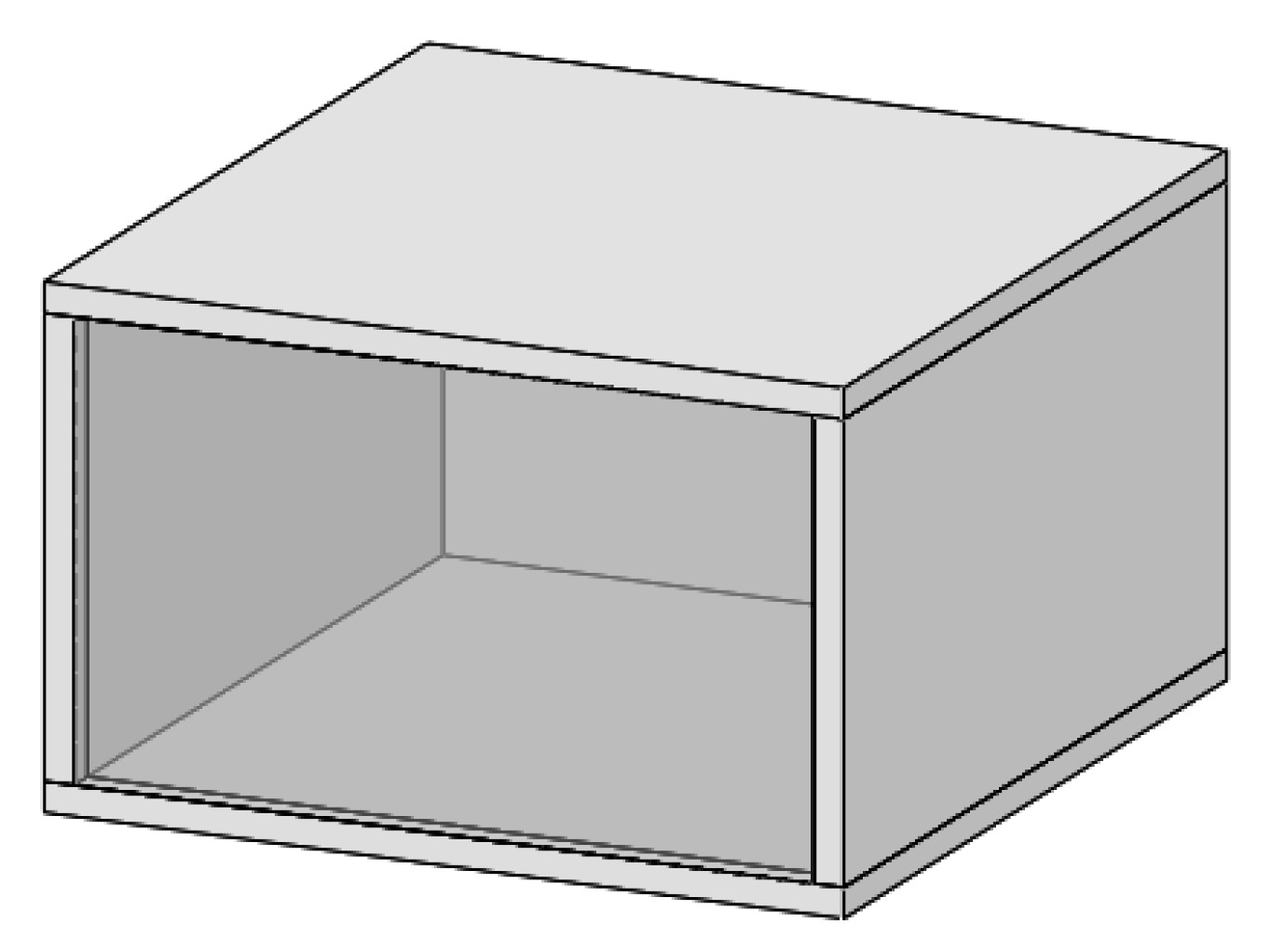
A box is designed to simulate the temperature-controlled box, as shown in Figure 4. The sinusoidal function of temperature variation with a period of 120 s is applied on the five inner surfaces of the box except the bottom surface to simulate the process of temperature control of the temperature-controlled box. The thermal stability of the swing micro-mirror structure under the thermal radiation on the inner surface of the box is analyzed through simulation. The applied function of temperature variation is shown in Table 5.
3.2.3. Finite Element Analysis Results of Thermal Stability
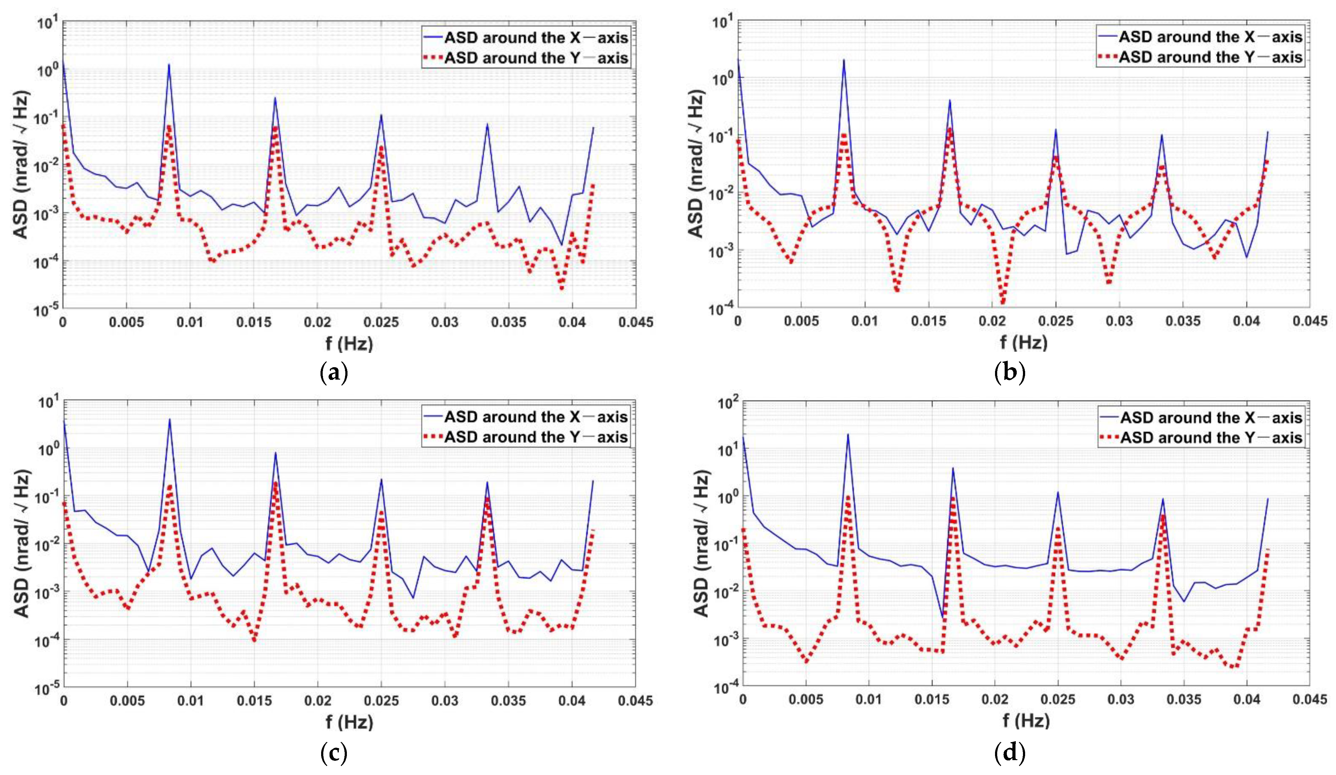
Finite element thermal analysis of the swing micro-mirror structure is carried out according to the four temperature variation functions in Table 5. The mirror angle deviation at each moment is converted into the amplitude spectral density (ASD) function. The corresponding curve is presented in Figure 5. Detailed data are shown in Figure 6. The outward direction perpendicular to the main view in Figure 1 is the positive direction of the Z-axis, the vertically downward direction is the positive direction of the Y-axis in the main view, and the left direction is the positive direction of the X-axis in the main view.
At the beginning of the simulation, the temperature of the mechanism fluctuates strongly. Then, it tends to change regularly. In order to obtain effective results, the mirror angle deviations from the 41st to the 50th period are selected to draw the curve of the amplitude spectral density function.
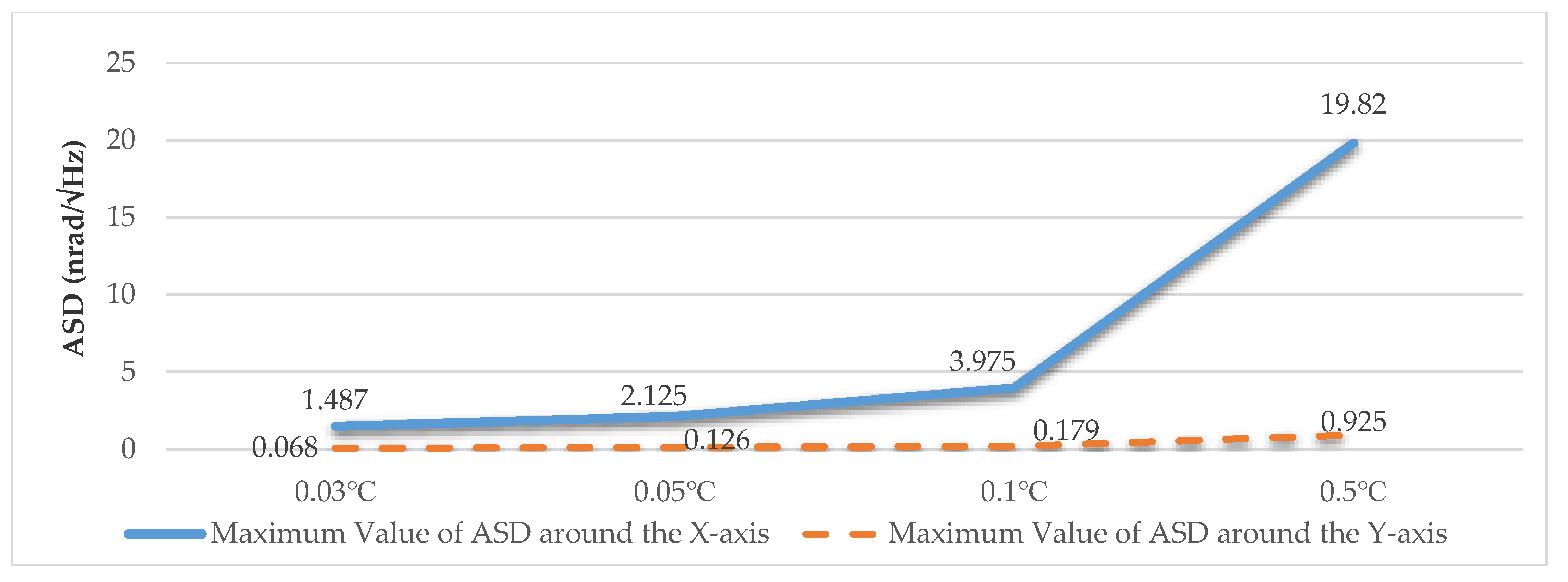
It can be seen from the data in Figure 6 that the maximum amplitude spectral density around the X-axis of the mechanism is greater than that around the Y-axis, with a difference of more than 10 times. Therefore, the value of the maximum amplitude spectral density around the X-axis can be regarded as the value of the total amplitude spectral density. By comparing results under four temperature variation ranges, it can be found that the value of the maximum amplitude spectral density increases with the increase of temperature range. The increase multiple is basically consistent with the increase of temperature range. According to the result of the simulation, when the temperature variation range is controlled within 0.1 °C, the amplitude spectral density of the mechanism is less than 5 nrad/√Hz, which can meet the requirement of design.
4. Discussion
According to the analysis in the previous section, it is reasonable to choose the temperature range of 0.1 °C as the condition of temperature control. In this section, the thermal stability of the swing micro-mirror structure will be further studied under the condition of temperature variation applied along the X-axis, Y-axis, and Z-axis, respectively.
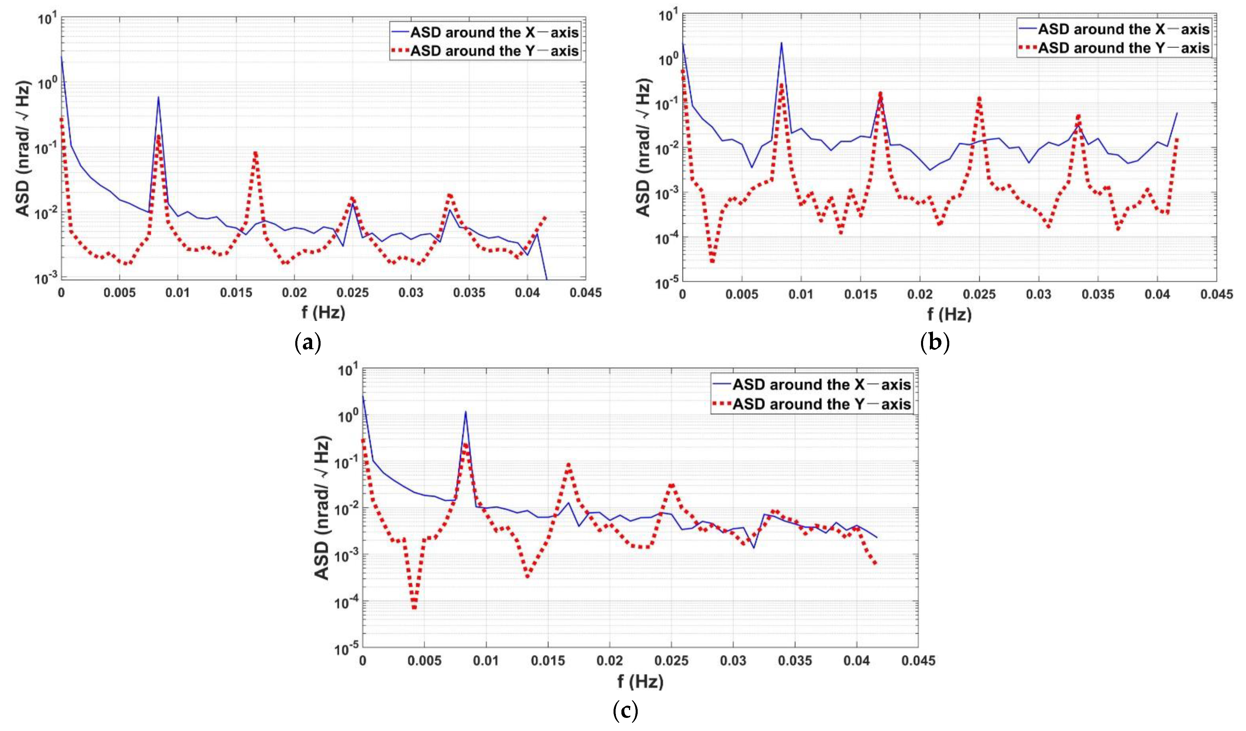
Two inner surfaces perpendicular to the X-axis, Y-axis, and Z-axis of the temperature-controlled box are selected respectively, and the function of temperature variation is applied to obtain the corresponding maximum value of amplitude spectral density function from the 41st to the 50th period, as shown in Figure 7. The corresponding curves of amplitude spectral density function are shown in Figure 8.
Figure 7 shows that the maximum amplitude spectral density around the X-axis is about 2.5 nrad/√Hz, and the maximum amplitude spectral density around the Y-axis is less than 0.6 nrad/√Hz under the three heating conditions. The value of the maximum amplitude spectral density around the X-axis is still greater than that around the Y-axis, which indicates that the thermal stability of the mechanism around the X-axis is not as good as that around the Y-axis. This is mainly due to the design of the mechanical structure of the mechanism.
In addition, when the temperature variation along the Y-axis is applied, the maximum amplitude spectral density around the Y-axis is significantly greater than that under the condition of heating along the X-axis and Z-axis, indicating that the thermal stability of the mechanism around the Y-axis would be obviously affected by temperature variation along the Y-axis. However, the thermal stability around the X-axis is not significantly affected by the heating direction. The maximum amplitude spectral densities around the X-axis are close to each other under the three heating conditions.
From the analysis above, it can be concluded that the thermal stability of the mechanism is closely related to its own mechanical structure. In order to improve the overall thermal stability of the mechanism, more attention should be paid to the design of the structure of the mechanism. The thermal stability of the mechanism can be enhanced by strengthening the structural stability around the X-axis.
5. Conclusions
This article introduces the design scheme of a kind of swing micro-mirror structure used in a space gravitational wave observatory and analyzes its thermal stability. It is proven that the amplitude spectral density of the mechanism is less than 5 nrad/√Hz when the range of temperature variation is controlled within 0.1 °C through finite element analysis, which can meet the requirement of design.
In addition, the thermal stability of the mechanism is analyzed when the temperature variations are applied in different directions. It is found that the thermal stability of the mechanism is mainly affected by its own mechanical structure. The thermal stability of the mechanism has a closed relationship with the structural stability around the X-axis. In the following design, the overall thermal stability of the mechanism can be improved by strengthening the structural stability around the X-axis.
After the structural design of the swing micro-mirror structure is completed, the solid model will be manufactured for experimental verification. The working environment of the mechanism in space can be simulated through temperature control in the vacuum environment. The angle deviations of the mirror at different moments can be measured by the dual-frequency laser interferometer. The amplitude spectral density function is obtained by processing the time domain data, so as to evaluate the thermal stability of the mechanism.
Author Contributions
Conceptualization, M.X.; Formal analysis, K.Z.; Funding acquisition, M.X.; Investigation, K.Z.; Methodology, K.Z.; Resources, M.X.; Software, K.Z. and M.X.; Supervision, M.X.; Writing—original draft, K.Z.; Writing—review & editing, M.X. Both authors have read and agreed to the published version of the manuscript.
Funding
This research was funded by the National Natural Science Foundation of China, grant number U1831108 and Natural Science Foundation of Jiangsu Province, grant number SBK2019020383.
Institutional Review Board Statement
Not applicable.
Informed Consent Statement
Not applicable.
Data Availability Statement
Not applicable.
Conflicts of Interest
The authors declare no conflict of interest.
References
- Cheng, J.; Yang, D. Progress in gravitational wave detection. Prog. Astron. 2005, 23, 195–204. [Google Scholar]
- Liu, J.; Wang, G.; Hu, Y.; Zhang, T.; Luo, Z.; Wang, Q.; Shao, L. GW150914 and gravitational-wave astronomy. Chin. Sci. Bull. 2016, 61, 1502–1524. [Google Scholar] [CrossRef] [Green Version]
- Hubert, H. Optimizing Orbits for (e)LISA. In Proceedings of the 11th International LISA Symposium, Zurich, Switzerland, 5–9 September 2016. [Google Scholar]
- Pijnenburg, J.; Rijnveld, N.; Hogenhuis, H. Extremely Stable Piezo Mechanisms for the New Gravitational Wave Observatory. In Proceedings of the SPIE Conference: Astronomical Telescopes + Instrumentation, Amsterdam, The Netherlands, 1–6 July 2012. [Google Scholar]
- Dennis, R.W.; Pierangelo, M.; Peter, W.; Hans, S.; Peter, G.; Ulrich, J. Alternative Opto-mechanical Architectures for the LISA Instrument. In Proceedings of the 7th International LISA Symposium, Barcelona, Spain, 16–20 June 2008. [Google Scholar]
- Lucarelli, S.; Scheulen, D.; Kemper, D.; Sippel, R.; Verlaan, A.; Hogenhuis, H.; Ende, D. The Breadboard Model of the LISA Telescope Assembly. In Proceedings of the International Conference on Space Optics 2012, Ajaccio, Corsica, France, 9–12 October 2012. [Google Scholar]
- Gert, W.; Jet, H.; Matthew, M. Realization and Testing of an Active Mirror Mechanism for In-field Pointing in eLISA. In Proceedings of the SPIE Conference: Astronomical Telescopes + Instrumentation, Edinburgh, UK, 26 June–1 July 2016. [Google Scholar]
- Xu, M.; Ji, H.; Xu, T.; Zhang, H.; Wu, Z. Random ground vibration response of the optical delay line system of a stellar interferometer. J. Vib. Shock 2017, 36, 159–164. [Google Scholar]
- Xu, M.; Xu, T.; Hu, Z.; Zhang, H.; Ji, H.; Jiang, H.; Wang, L. Research and implementation of OPD algorithm for spatial gravitational wave telescope based on ZEMAX and Python softwares. J. Appl. Opt. 2017, 38, 872–876. [Google Scholar]
- Rijnveld, N.; Pijnenburg, J. Picometer Stable Scan Mechanism for Gravitational Wave Detection in Space. In Proceedings of the SPIE Conference: Astronomical Telescopes + Instrumentation, San Diego, CA, USA, 27 June–2 July 2010. [Google Scholar]
- Song, L.; Yang, S.; Chen, Z. Optimization design and analysis of the structure of beryllium mirrors of astronomical instruments in space. Infrared Laser Eng. 2009, 38, 882–888. [Google Scholar]
- Lobontiu, N.; Paine, J.; Garcia, E.; Goldfarb, M. Corner-filleted flexure hinges. Asme J. Mech. Des. 2001, 123, 346–352. [Google Scholar] [CrossRef]
- Zhai, Y.; Mei, G.; Jiang, F. Φ2020 mm aperture space infrared camera main reflector design. Chin. J. Lumin. 2018, 39, 1170–1176. [Google Scholar] [CrossRef]
- Slavov, S.; Konsulova-Bakalova, M. Optimizing weight of housing elements of two-stage reducer by using the topology management optimization capabilities integrated in SOLIDWORKS: A case study. Machines 2019, 7, 9. [Google Scholar] [CrossRef] [Green Version]
- Wang, B.; Wang, X.; Chen, F. Engineering Measurement Technology, 2nd ed.; Tsinghua University Press: Beijing, China, 2012; pp. 68–69. [Google Scholar]
- Zhang, Y. ANSYS Workbench 15.0 Finite Element Analysis from Beginners to Masters, 1st ed.; China Machine Press: Beijing, China, 2014; pp. 207–208, 347–348. [Google Scholar]
- Xu, J. ANSYS Workbench 2020 Complete Self-Study Manual, 1st ed.; Publishing House of Electronics Industry Press: Beijing, China, 2020; pp. 384–385. [Google Scholar]
Figure 1.
3D model of the assembly of the swing micro-mirror structure: (a) right view; (b) main view; (c) left view; (d) upper view.
Figure 1.
3D model of the assembly of the swing micro-mirror structure: (a) right view; (b) main view; (c) left view; (d) upper view.

Figure 2.
3D model of the parts of the swing micro-mirror structure: (a) framework; (b) mirror cell; (c) mirror fixed plate; (d) mirror; (e) flexible hinge A; (f) flexible hinge B; (g) flexible arm; (h) actuator connecting plate; (i) actuator keep plate; (j) actuator; (k) supporting foot A; (l) supporting foot B.

Figure 3.
Development of the model of swing micro-mirror structure.

Figure 4.
Model of the temperature-controlled box.

Figure 5.
Amplitude spectral density (ASD) corresponding to four temperature variation functions: (a) 0.03 °C; (b) 0.05 °C; (c) 0.1 °C; (d) 0.5 °C.
Figure 5.
Amplitude spectral density (ASD) corresponding to four temperature variation functions: (a) 0.03 °C; (b) 0.05 °C; (c) 0.1 °C; (d) 0.5 °C.

Figure 6.
Amplitude spectral density under different temperature variations.

Figure 7.
Amplitude spectral density corresponding to different heating directions.

Figure 8.
Amplitude spectral density function in three heating directions: (a) Heating on the inner surface perpendicular to the X-axis; (b) Heating on the inner surface perpendicular to the Y-axis; (c) Heating on the inner surface perpendicular to the Z-axis.
Figure 8.
Amplitude spectral density function in three heating directions: (a) Heating on the inner surface perpendicular to the X-axis; (b) Heating on the inner surface perpendicular to the Y-axis; (c) Heating on the inner surface perpendicular to the Z-axis.


Table 1.
Materials of parts.
| Materials | Parts |
|---|---|
| Invar | framework, mirror cell, supporting foot A, supporting foot B |
| Titanium Alloy | mirror fixed plate, flexible arm, actuator connecting plate, actuator keep plate |
| Ti6Al4V | flexible hinge A, flexible hinge B |
| Zerodur | mirror |
Table 2.
Properties of different materials.
| Material | Density (kg/m−3) | Coefficient of Thermal Expansion (c−1) | Young’s Modulus (MPa) | Poisson’s Ratio | Tensile Yield Strength (MPa) | Compressive Yield Strength (MPa) |
|---|---|---|---|---|---|---|
| Invar | 8050 | 5.00 × 10⁻⁷ | 141,000 | 0.29 | 274 | 274 |
| Titanium Alloy | 4620 | 9.40 × 10⁻⁶ | 96,000 | 0.36 | 930 | 930 |
| Ti6Al4V | 4540 | 7.89 × 10⁻⁶ | 110,000 | 0.34 | 860 | 970 |
| Zerodur | 2530 | 1.00 × 10⁻⁷ | 90,300 | 0.24 | 358.90 | 500.83 |
Table 3.
Parameters of the initial model and final model of the swing micro-mirror structure.
| Model | Weight (kg) | Size mm |
|---|---|---|
| Initial | ||
| Final |
Table 4.
The 1st to 6th natural frequencies of the swing micro-mirror structure.
| Mode No. | Frequency (Hz) |
|---|---|
| 1 | 247.55 |
| 2 | 452.90 |
| 3 | 890.04 |
| 4 | 1066.00 |
| 5 | 1267.20 |
| 6 | 1381.90 |
Table 5.
Temperature variation functions.
| No. | Initial Temperature (°C) | Cycle (s) | Temperature Variation (°C) | Functions |
|---|---|---|---|---|
| 1 | 22 | 120 | 0.03 | |
| 2 | 22 | 120 | 0.05 | |
| 3 | 22 | 120 | 0.1 | |
| 4 | 22 | 120 | 0.5 |
Publisher’s Note: MDPI stays neutral with regard to jurisdictional claims in published maps and institutional affiliations. |
© 2021 by the authors. Licensee MDPI, Basel, Switzerland. This article is an open access article distributed under the terms and conditions of the Creative Commons Attribution (CC BY) license (https://creativecommons.org/licenses/by/4.0/).
Share and Cite
MDPI and ACS Style
Zheng, K.; Xu, M. Design and Thermal Stability Analysis of Swing Micro-Mirror Structure for Gravitational Wave Observatory in Space. Machines 2021, 9, 104. https://0-doi-org.brum.beds.ac.uk/10.3390/machines9050104
AMA Style
Zheng K, Xu M. Design and Thermal Stability Analysis of Swing Micro-Mirror Structure for Gravitational Wave Observatory in Space. Machines. 2021; 9(5):104. https://0-doi-org.brum.beds.ac.uk/10.3390/machines9050104
Chicago/Turabian StyleZheng, Kunyao, and Mingming Xu. 2021. "Design and Thermal Stability Analysis of Swing Micro-Mirror Structure for Gravitational Wave Observatory in Space" Machines 9, no. 5: 104. https://0-doi-org.brum.beds.ac.uk/10.3390/machines9050104
Note that from the first issue of 2016, this journal uses article numbers instead of page numbers. See further details here.